A Wireless Intraocular Pressure Sensor with Variable...
6
JOURNAL OF SEMICONDUCTOR TECHNOLOGY AND SCIENCE, VOL.13, NO.4, AUGUST, 2013 http://dx.doi.org/10.5573/JSTS.2013.13.4.355 Manuscript received Dec. 25, 2012; accepted May. 7, 2013 * School of Electronic Engineering, College of Information Technology, Soongsil University, 511 Sangdo-Dong, Dongjak-Gu, 156-743, Republic of Korea ** Nano-Bio Research Center, Korea Institute of Science and Technology, 39-1 Hawolgok-Dong, Seongbuk-Gu, Seoul, 136-791, Republic of Korea *** School of Electrical Engineering, College of Engineering, Soongsil University, 511 Sangdo-Dong, Dongjak-Gu, 156-743, Republic of Korea E-mail : [email protected] A Wireless Intraocular Pressure Sensor with Variable Inductance Using a Ferrite Material Byungjoo Kang * , Hoyong Hwang * , Soo Hyun Lee ** , Ji Yoon Kang ** , Joung-Hu Park *** , Chulhun Seo * , and Changkun Park * Abstract—A wireless intraocular (IOP) pressure sensor based on micro electro mechanical system (MEMS) technology is proposed. The proposed IOP sensor uses variable inductance according to the external pressure. The proposed sensor is composed of two flexible membranes: a ferrite bottom part, an inductor, and a capacitor. The inductance of the sensor varies according to the external pressure. The resonance frequency of the sensor is also varied, and this frequency is detected using an external coil. The external coil is designed with an FR-4 printed circuit board. The feasibility of the proposed sensor structure using variable inductance to detect the external pressure is successfully demonstrated. Index Terms—Ferrite, IOP sensor, resonance frequency, variable inductance I. INTRODUCTION Techniques in health-care are becoming more important as living standards are increasing. Wireless engineering has been adapted to many health-care techniques because wireless engineering can provide convenience for the detection of bionic signals [1-5]. For example, radar engineering can provide a method of non- contact heartbeat detection. Fig. 1 shows a simplified version of a wireless IOP monitoring system. An IOP sensor located in the eyeball detects the intraocular pressure and the pressure is converted to the impedance variance of the IOP sensor. The varied impedance of the sensor is detected by the external coil and the electrical signal from the coil is interpreted by the impedance analyzer or by an external reader. Finally, a mechanical valve located in the eyeball controls the IOP according to the information from the external reader. The design of the IOP sensor is therefore the key technology for this type of wireless IOP monitoring system. The IOP sensor needs to have the ability to use the variation of the IOP pressure to vary the electrical parameters. In this study, a sensor for a wireless intraocular pressure (IOP) detection system is proposed and designed. Recently, IOP sensors that use the capacitance as it varies with the pressure have been intensely studied [6-8]. However, IOP sensors using variable capacitance require complicated micro electro mechanical system Fig. 1. Simplified wireless IOP sensor monitoring system.
Transcript of A Wireless Intraocular Pressure Sensor with Variable...
JOURNAL OF SEMICONDUCTOR TECHNOLOGY AND SCIENCE, VOL.13, NO.4, AUGUST, 2013 http://dx.doi.org/10.5573/JSTS.2013.13.4.355
Manuscript received Dec. 25, 2012; accepted May. 7, 2013 * School of Electronic Engineering, College of Information Technology,
Soongsil University, 511 Sangdo-Dong, Dongjak-Gu, 156-743, Republic
of Korea ** Nano-Bio Research Center, Korea Institute of Science and Technology,
39-1 Hawolgok-Dong, Seongbuk-Gu, Seoul, 136-791, Republic of Korea *** School of Electrical Engineering, College of Engineering, Soongsil
University, 511 Sangdo-Dong, Dongjak-Gu, 156-743, Republic of Korea
E-mail : [email protected]
A Wireless Intraocular Pressure Sensor with Variable
Inductance Using a Ferrite Material
Byungjoo Kang*, Hoyong Hwang
*, Soo Hyun Lee
**, Ji Yoon Kang
**, Joung-Hu Park
***, Chulhun Seo
*,
and Changkun Park*
Abstract—A wireless intraocular (IOP) pressure
sensor based on micro electro mechanical system
(MEMS) technology is proposed. The proposed IOP
sensor uses variable inductance according to the
external pressure. The proposed sensor is composed
of two flexible membranes: a ferrite bottom part, an
inductor, and a capacitor. The inductance of the
sensor varies according to the external pressure. The
resonance frequency of the sensor is also varied, and
this frequency is detected using an external coil. The
external coil is designed with an FR-4 printed circuit
board. The feasibility of the proposed sensor structure
using variable inductance to detect the external
pressure is successfully demonstrated.
Index Terms—Ferrite, IOP sensor, resonance frequency,
variable inductance
I. INTRODUCTION
Techniques in health-care are becoming more
important as living standards are increasing. Wireless
engineering has been adapted to many health-care
techniques because wireless engineering can provide
convenience for the detection of bionic signals [1-5]. For
example, radar engineering can provide a method of non-
contact heartbeat detection.
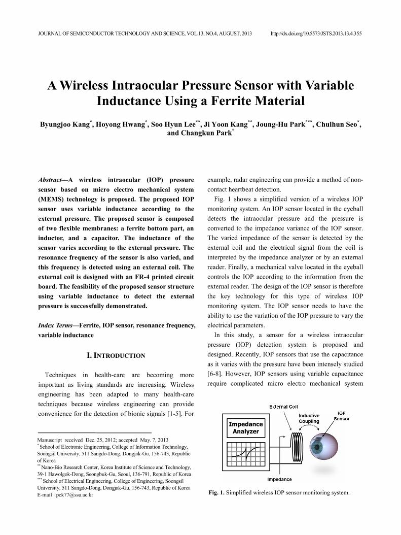
Fig. 1 shows a simplified version of a wireless IOP
monitoring system. An IOP sensor located in the eyeball
detects the intraocular pressure and the pressure is
converted to the impedance variance of the IOP sensor.
The varied impedance of the sensor is detected by the
external coil and the electrical signal from the coil is
interpreted by the impedance analyzer or by an external
reader. Finally, a mechanical valve located in the eyeball
controls the IOP according to the information from the
external reader. The design of the IOP sensor is therefore
the key technology for this type of wireless IOP
monitoring system. The IOP sensor needs to have the
ability to use the variation of the IOP pressure to vary the
electrical parameters.
In this study, a sensor for a wireless intraocular
pressure (IOP) detection system is proposed and
designed. Recently, IOP sensors that use the capacitance
as it varies with the pressure have been intensely studied
[6-8]. However, IOP sensors using variable capacitance
require complicated micro electro mechanical system
Fig. 1. Simplified wireless IOP sensor monitoring system.

356 BYUNGJOO KANG et al : A WIRELESS INTRAOCULAR PRESSURE SENSOR WITH VARIABLE INDUCTANCE USING …
(MEMS) processes. Although IOP sensors using variable
inductance were proposed in previous works [9], the
complexity of the MEMS processes in those works was
not moderated.
We propose an IOP sensor that uses variable
inductance with a simple MEMS process. We achieve
variable inductance using a variable distance between the
ferrite material used in the design and the pattern of an
inductor according to the external pressure. Additionally,
we propose a method to improve the pressure sensitivity
at high resolution. This method utilizes two flexible
membranes in the ferrite material and in the inductor
pattern.
Finally, the proposed IOP sensor is designed using
simple MEMS technology. It is composed of flexible
membranes, a ferrite bottom part, an inductor, and a
capacitor. Variation of the external pressure of the sensor
changes the values of the inductance of the inductor
pattern. If the external pressure increases, the distance
between the inductor pattern and the ferrite material
decreases and the resonance frequency of the sensor
decreases. Similarly, if the external pressure decreases,
the resonance frequency of the sensor increases. From
the detected resonance frequency of the sensor using an
external coil, the IOP pressure can be detected.
II. PROPOSED IOP SENSOR AND OPERATION
PRINCIPLE
We propose an IOP sensor in which the inductance is
designed to vary according to the external pressure. The
proposed IOP sensor is composed of a spiral inductor, a
silicon substrate, two flexible membranes, the afore-
mentioned ferrite material, and a metal-insulator-metal
(MIM) capacitor. It is implemented using MEMS
technology, as shown in Fig. 2. The inductor pattern and
the ferrite material are attached to the flexible
membranes. The inside of the IOP sensor is designed to
be isolated perfectly from the outside of the sensor. The
MEMS process steps for the proposed IOP sensor, which
uses variable inductance according to the external
pressure, is simpler than that of an IOP sensor that uses
variable capacitance.
Fig. 3(a) shows a cross-section of the proposed IOP
sensor. The resonance frequency of the IOP sensor is
determined using the inductance and the parasitic
capacitance. If the external pressure of the IOP sensor
increases, the distance between the spiral inductor and
the ferrite bottom part, located on the flexible membranes,
decreases, as shown in Fig. 3(b). The magnetic flux
generated by the AC current of the spiral inductor is then
focused on the ferrite, causing the self-inductance of the
IOP sensor to increase. With ferrite as the bottom
material, the increase in the external pressure of the IOP
sensor shortens the distance between the spiral inductor
and the bottom ferrite, finally decreasing the resonance
frequency. In the proposed IOP sensor, we use two
flexible membranes to increase the resolution.
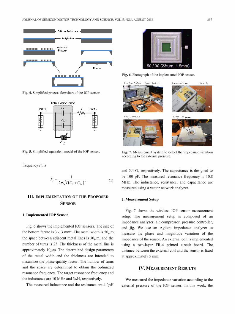
Fig. 4 provides a simplified process flowchart of the
investigated IOP sensor. The flexible membrane and the
inductor pattern are implemented using polyimide and
copper, respectively. A high frequency NiZn ferrite is
attached on the bottom flexible membrane as shown in
Fig. 4.
Fig. 5 shows the simplified equivalent circuit of the
proposed IOP sensor. The R of the circuit denotes the
parasitic resistance of the spiral inductor. In addition, CS
is the parasitic capacitance between the adjacent metals
of the inductor, CM denotes the MIM capacitor, and L is
the inductance of the spiral inductor. Thus, the resonance
Fig. 2. Layers of the IOP sensor.
(a) (b)
Fig. 3. Cross-section of the proposed IOP sensor (a) without
external pressure, (b) with external pressure.
JOURNAL OF SEMICONDUCTOR TECHNOLOGY AND SCIENCE, VOL.13, NO.4, AUGUST, 2013 357
frequency Fr is
( )MS
rCCL
F+
=π2
1. (1)
III. IMPLEMENTATION OF THE PROPOSED
SENSOR
1. Implemented IOP Sensor
Fig. 6 shows the implemented IOP sensors. The size of
the bottom ferrite is 3 × 3 mm2. The metal width is 50µm,
the space between adjacent metal lines is 30µm, and the
number of turns is 23. The thickness of the metal line is
approximately 10µm. The determined design parameters
of the metal width and the thickness are intended to
maximize the phase-quality factor. The number of turns
and the space are determined to obtain the optimized
resonance frequency. The target resonance frequency and
the inductance are 10 MHz and 3µH, respectively.
The measured inductance and the resistance are 4.0µH
and 5.4 Ω, respectively. The capacitance is designed to
be 100 pF. The measured resonance frequency is 10.8
MHz. The inductance, resistance, and capacitance are
measured using a vector network analyzer.
2. Measurement Setup
Fig. 7 shows the wireless IOP sensor measurement
setup. The measurement setup is composed of an
impedance analyzer, air compressor, pressure controller,
and jig. We use an Agilent impedance analyzer to
measure the phase and magnitude variation of the
impedance of the sensor. An external coil is implemented
using a two-layer FR-4 printed circuit board. The
distance between the external coil and the sensor is fixed
at approximately 5 mm.
IV. MEASUREMENT RESULTS
We measured the impedance variation according to the
external pressure of the IOP sensor. In this work, the
Fig. 4. Simplified process flowchart of the IOP sensor.
Fig. 5. Simplified equivalent model of the IOP sensor.
Fig. 6. Photograph of the implemented IOP sensor.
Fig. 7. Measurement system to detect the impedance variation
according to the external pressure.

358 BYUNGJOO KANG et al : A WIRELESS INTRAOCULAR PRESSURE SENSOR WITH VARIABLE INDUCTANCE USING …
distance between the external coil and the sensor is fixed
at approximately 5 mm. The external pressure applied to
the IOP sensor ranges from 0 mmHg to 90 mmHg. For
this measurement, we used an air pressure controller.
Fig. 8(a) shows the measured results according to the
external pressure of the IOP sensor without a cornea. The
resolution frequencies according to the external pressure
are summarized in Fig. 8(b). The resonance frequency of
the IOP sensor under 0 mmHg pressure was found to be
10.8 MHz. If the external pressure increases, the
resonance frequency decreases because the inductance of
the sensor increases, as predicted in the previous section.
The resonance frequency of the sensor does not vary if
the external pressure is higher than 70 mmHg. At a
pressure of 70 mmHg, the ferrite bottom material and the
upper flexible membrane of the sensor adhere to each
other. The dynamic range of the designed sensor is
therefore 0 mmHg to 70 mmHg. The dynamic range of
the sensor is determined from the flexibility of the
membranes. The flexibility can be controlled using the
thickness of the flexible membrane.
A measurement similar to that shown in Fig. 8 is
performed with a cornea located between an external coil
and the designed IOP sensor, as shown in Fig. 9(a). The
resolution frequencies according to the external pressure
are summarized in Fig. 9(b).
V. DISCUSSION
The quality factor of the measured results shown in
Fig. 9(a) is lower than that shown in Fig. 8(a) because the
electrolyte of the cornea degrades the coupling
characteristics between the external coil and the designed
IOP sensor. In general, the conductivity of tissues is
higher than that of air. The eddy current generated on the
surface of the cornea therefore degrades the magnetic
coupling between the external coil and the IOP sensor
and hence the quality factor. The conductivity of the
cornea can vary according to the water concentration on
the surface of the cornea. However, the resonance
(a)
(b)
Fig. 8. Measured results according to the external pressure
without a cornea (a) phase, (b) resonance frequency of IOP
sensor.
(a)
(b)
Fig. 9. Measured results according to the external pressure with
a cornea (a) phase, (b) resonance frequency of IOP sensor.

JOURNAL OF SEMICONDUCTOR TECHNOLOGY AND SCIENCE, VOL.13, NO.4, AUGUST, 2013 359
frequency and dynamic range characteristics are nearly
identical to the results shown in Fig. 8(a).
VI. CONCLUSIONS
We have proposed an intraocular pressure (IOP)
sensor based on MEMS technology. We have also
proposed that the inductance varies under external
pressure, which is detected by the detector IOP. Ferrite
bottom material on a flexible membrane is used for the
variable inductance. We use two flexible membranes to
enhance the resolution of the sensor. We obtained the
measured results at a resonance frequency of 10.8 MHz
and a dynamic range of 70 mmHg. Finally, we
successfully demonstrated the feasibility of the proposed
sensor.
ACKNOWLEDGMENTS
This research was supported by the Bio &Medical
Technology Development Program of the National
Research Foundation (NRF) funded by the Korean
government (MEST) (No. 2009-0091931) and the
Soongsil University Research Fund of 2010.
REFERENCES
[1] Y.-H. Kim, E.-S. Hwang, and Y.-J. Kim,
“Polymer/Metal Based Flexible MEMS Biosensors
for Nerve Signal Monitoring and Sensitive Skin,”
Journal of Semiconductor Technology and Science,
vol.5, no.1, pp. 11-16, 2005.
[2] C. Lee, J. Park, and C. Park, “X-band CMOS
power amplifier using mode-locking method for
sensor applications,” J. of Electromagn. Waves and
Appl., vol. 26, no. 5-6, pp. 633-604, 2012.
[3] L.-M. Santiago, et al., “Design of a system for
continuous intraocular pressure monitoring,” IEEE
Transactions on Instrumentation and Measurement,
vol. 54, no. 4, pp. 1534-1540, August 2005.
[4] A. Baldi, W. Choi, and B. Ziaie, “A self-resonant
frequency-modulated micromachined passive
pressure transensor,” IEEE Sensors Journal, vol. 3,
no. 6, pp. 728-733, December 2003.
[5] P. –J. Chen, D. C. Rodger, S. Saati, M. S. Humayun,
Y. -C. Tai, “Microfabricated Implantable parylene-
based wireless passive intraocular pressure
sensors,” Journal of Microelectromechanical Systems,
vol. 17, no. 6, pp. 1342-1351, December 2008.
[6] J. Coosemans, M. Catrysse, and R. Puers, “A
readout circuit for and intra-ocular pressure
sensor,” Sensors and Actuators: Physical, vol. 110,
no. 1-3, pp. 432-438, February 2004.
[7] P.-J. Chen, D. C. Rodger, S. Saati, M. S. Humayun,
and Y.-C. Tai, “Microfabricated Implantable
Parylene-Based Wireless Passive Intraocular
Pressure Sensors,” Journal of Microelectro-
mechanical Systems. vol. 17. no. 6, pp. 1342-1351,
December 2008.
[8] D. Ha, T.-Y. Lin, W. N. de Vriesy, B. Kim, A. L.
Chlebowskiz, S. W. M. Johny, P. P. Irazoquiz, and
W. J. Chappell, “A Compact-Size Packaged Third-
Order Harmonic Tag for Intraocular Pressure (IOP)
Monitoring inside a Mouse Eye,” 2012 IEEE MTT-
S International Microwave Symposium Digest, pp.
1-3, June 2012.
[9] P.-J. Chen, D. C. Rodger, E. Meng, M. S.
Humayun, and Y. -C. Tail, “Implantable
unpowered Parylene MEMS Intraocular Pressure
Sensor,” 2006 International Conference on Micro-
technologies in Medicine and Biology, pp. 256-
259-3, May 2006.
Byungjoo Kang received the B.S.
degree in electronic engineering from
Soongsil University, Seoul, in 2011.
His current research interests include
radar systems and RF power amplifier.
Hoyong Hwang received the B.S.
degree in electronic engineering from
Soongsil University, Seoul, in 2012,
and is currently working toward the
M.S. degree at Soongsil University.
His current research interests include
CMOS RF power amplifiers.
360 BYUNGJOO KANG et al : A WIRELESS INTRAOCULAR PRESSURE SENSOR WITH VARIABLE INDUCTANCE USING …
Soo Hyun Lee received the B.S.
degree from the Department of
Electrical Engineering, Korea
University, Seoul, Korea, in 2002,
the M.S. degree and Ph.D. degree
from the Department of Electrical
and Computer Engineering and
Computer Science, University of Cincinnati, in 2004 and
2007. In 2006, he joined the Korea Institute of Science
and Technology (KIST), Seoul, Korea, where he is
currently a Senior Researcher. His research interests
include implantable sensors, neural electrodes, biosensors,
and cell chips.
Ji Yoon Kang received the B.S.,
M.S., and Ph.D. degrees in Mechanical
Engineering from Seoul National
University, Korea, in 1990, 1992,
and 1997, respectively. From 1997 to
2001, he was a Research scientist at
Samsung Advanced Institute of
Science and Technology, Korea. From 2003 to 2004, he
was a visiting scholar at the University of Cincinnati. In
2001, he joined the Korea Institute of Science and
Technology, Seoul, Korea, where he is currently an
Principal Researcher. His research interests include
microfluidics, biosensor, and implantable micro-devices.
Joung-Hu Park received his B.S.,
M.S., and Ph.D. from the Department
of Electrical Engineering and
Computer Science of Seoul National
University, Seoul, Korea, in 1999,
2001 and 2006, respectively. He is
currently an Assistant Professor at
Soongsil University, Seoul, Korea. His current research
interests include the analysis of high-frequency switching
converters and renewable energy applications.
Chulhun Seo received the B.S., M.S.,
and Ph.D. degrees from Seoul
National University, Seoul, Korea, in
1983, 1985, and 1993, respectively,
all in electronics engineering. From
1993 to 1995, he was a Postdoctoral
Research Scientist with the Massachusetts Institute of
Technology (MIT), Cambridge. He has been a Professor
with Soongsil University, Seoul, since 1993. He has also
been a Member of the Research Staff with the Research
Laboratory of Electronics, MIT, since March 1995. His
current researchinterests include wireless and microwave
components, metamaterial, wireless power transfer
system, microwave integrated circuits and radar, as well
as microwave circuits and RFICs.
Changkun Park received the B.S.,
M.S., and Ph.D. degrees in electrical
engineering from Korea Advanced
Institute of Science and Technology
(KAIST), Daejeon, Korea, in 2001,
2003, and 2007, respectively. From
2007 to 2009, he was with the
Advanced Design Team of DRAM Development
Division, Hynix Semiconductor Inc., Icheon, Korea,
where he was involved in development of high-speed I/O
interfaces of DRAM. In September 2009, he joined the
faculty of the School of Electronic Engineering, Soongsil
University, Seoul, Korea. His research interests include
RF and millimeter-wave circuits, RF CMOS power
amplifier, and wireless chip-to-chip communications.