PlexPower Factory Sealed Panelboard Increased Safety
27
DISTRIBUTION EQUIPMENT: ATEX/IECEx INCREASED SAFETY PANELBOARDS Visit our website at www.emerson.com or contact us at (800) 621-1506. © June 2017 361 ATEX/IECEx: Zone 1 and 2 - 21 and 22 II2GD EPL Gb Db Ex db eb IIB+H 2 Ex tb IIIC IP66/Ik10 ATEX/IECEx — Optional: Zone 1 and 2 - 21 and 22 II2GD EPL Gb Db Ex db eb IIC Ex tb IIIC IP66/Ik10 Applications • The IEC PlexPower™ factory sealed panelboard provides indoor and outdoor protection and control of electrical circuits in hazardous environments such as: — Petroleum plants — Chemical plants — Refineries — Other process facilities • Ideal for placement in wet, corrosive environments or where flammable gases or vapors are likely to be present. • Suitable for use on lighting, heat trace and power circuits. Features • No external conduit or cable seals required thus making installations faster, easier, and less costly. • Limitless flexibility through horizontal and vertical coupling options. • The PlexPower™ factory sealed panelboard features a ground-breaking design that uses individual breaker housings to minimize the downtime and costs associated with servicing circuit breakers in hazardous locations. • The lighter weight panelboard enclosure can be quickly opened in the field for easier servicing. • Supplied as standard: — Bottom entries with brass earth plate — Pre-drilled supplied with non Ex certified temporary plastic plugs — Standard hard wired, copper cables — Color coded wiring for phases; neutral (blue) and ground (yellow/green) — Internal actuators — Internal wiring duct — Phenolic nameplate (specify legend) • Optional gland plate at the bottom of enclosure can be easily field punched or drilled for cable or conduit entries. See options. • 1 circuit to 72 circuit panelboard configurations are standard, with or without main breaker. • Schneider breakers are supplied as standard, making replacements readily available. • PlexPower™ breakers accommodate ABB breakers. For a custom panelboard designed with ABB breakers, contact your local sales representative. • Branch circuit breakers available in 1-, 2- 3- and 4-pole. Current ratings on branch breakers: — 1-pole: 120, 240 Volts, 63 Amps maximum. — 2-, 3- and 4-pole: 240 and 415 Volts, 63 Amps maximum. • Branch breakers are labeled with numbers: — Odd numbers for line side — Even numbers for load side. — Labeled with inside breaker details • Main circuit breaker: — 40 to 250 Amps, 2- , 3- or 4-pole. • Branch and main breakers can be padlocked in either the “On” or “Off” position. • Breaker modules supplied with captive bolts. • Ground bar provided as standard. • External ground lug provided as standard. • 240/415 Volt breaker module 8-pole terminal wire range 2.5 mm 2 through 10 mm 2 (standard), 16 mm 2 with special lug. • 600 Volt main breaker module 4-pole terminal wire range 16 mm 2 through 150 mm 2 . • Ambient temperature ratings: — Standard model: -25 °C to +55 °C (-13 °F to +131 °F). — Standard model without switching: -40 °C (-40 °F) Standard Materials • Enclosure: fiberglass reinforced polyester (FRP) • Hardware: stainless steel • Bus bar: hard drawn copper • Chassis: hot dip galvanized for wall mounting use Options Must be listed in alphanumeric sequence at the end of the catalog number. • Drain, add suffix —D. • Drain/breather, add suffix —DV. • Gland plate bottom only, specify suffix —GPP = plastic gland plate, —GPB = brass gland plate. • Stainless steel legend plate (specify legend), add suffix —SP. • Voltmeter, add suffix —VM . • Ammeter, add suffix —AM . • Cable glands installed, add suffix —CG; (cable details to be provided by customer). • For Ex de IIC, add suffix —IIC. • Optional frame (structure) for floor mounting, self standing with and without canopy, contact your local sales representative for additional information. Schneider is a registered trademark of Schneider Electric. ABB Asea Brown Boveri Ltd is registered with the commercial register of Zurich, Switzerland. Please contact your local sales representative for Voltmeter and Ammeter options. PlexPower ™ Factory Sealed Panelboard Increased Safety
Transcript of PlexPower Factory Sealed Panelboard Increased Safety

DISTRIBUTION EQUIPMENT: ATEX/IECEx INCREASED SAFETY PANELBOARDS
Visit our website at www.emerson.com or contact us at (800) 621-1506. © June 2017
361
ATEX/IECEx: Zone 1 and 2 - 21 and 22
II2GD EPL Gb Db Ex db eb IIB+H2 Ex tb IIIC IP66/Ik10
ATEX/IECEx — Optional: Zone 1 and 2 - 21 and 22
II2GD EPL Gb Db Ex db eb IIC Ex tb IIIC IP66/Ik10
Applications• The IEC PlexPower™ factory sealed panelboard provides
indoor and outdoor protection and control of electrical circuits in hazardous environments such as:
—Petroleumplants —Chemicalplants —Refineries —Otherprocessfacilities• Ideal for placement in wet, corrosive environments or where
flammablegasesorvaporsarelikelytobepresent.• Suitable for use on lighting, heat trace and power circuits.
Features• No external conduit or cable seals required thus making
installations faster, easier, and less costly. • Limitlessflexibilitythroughhorizontalandverticalcoupling
options.• The PlexPower™ factory sealed panelboard features a
ground-breaking design that uses individual breaker housings to minimize the downtime and costs associated with servicing circuit breakers in hazardous locations.
• The lighter weight panelboard enclosure can be quickly opened inthefieldforeasierservicing.
• Supplied as standard:—Bottomentrieswithbrassearthplate—Pre-drilledsuppliedwithnonExcertifiedtemporaryplastic
plugs—Standardhardwired,coppercables—Colorcodedwiringforphases;neutral(blue)andground
(yellow/green)—Internalactuators—Internalwiringduct—Phenolicnameplate(specifylegend)
• Optional gland plate at the bottom of enclosure can be easily fieldpunchedordrilledforcableorconduitentries.See options.
• 1circuitto72circuitpanelboardconfigurationsarestandard,with or without main breaker.
• Schneider breakers are supplied as standard, making replacements readily available.
• PlexPower™ breakers accommodate ABB breakers. For a custom panelboard designed with ABB breakers, contact your local sales representative.
• Branch circuit breakers available in 1-, 2- 3- and 4-pole. Current ratings on branch breakers:
—1-pole:120,240Volts,63Ampsmaximum. —2-,3-and4-pole:240and415Volts,63Ampsmaximum.• Branch breakers are labeled with numbers:
—Oddnumbersforlineside—Evennumbersforloadside.—Labeledwithinsidebreakerdetails
• Main circuit breaker: —40to250Amps,2-,3-or4-pole.• Branch and main breakers can be padlocked in either the “On”
or “Off” position. • Breaker modules supplied with captive bolts.• Ground bar provided as standard.• External ground lug provided as standard.
• 240/415 Volt breaker module 8-pole terminal wire range 2.5 mm2 through 10 mm2 (standard), 16 mm2 with special lug.
• 600 Volt main breaker module 4-pole terminal wire range 16 mm2 through 150 mm2.
• Ambient temperature ratings:—Standardmodel:-25°Cto+55°C(-13°Fto+131°F).—Standardmodelwithoutswitching:-40°C(-40°F)
Standard Materials• Enclosure:fiberglassreinforcedpolyester(FRP)• Hardware: stainless steel• Bus bar: hard drawn copper• Chassis: hot dip galvanized for wall mounting use
Options Must be listed in alphanumeric sequence at the end of the catalog number.
• Drain,addsuffix—D.• Drain/breather,addsuffix—DV.• Glandplatebottomonly,specifysuffix—GPP = plastic gland
plate,—GPB = brass gland plate.• Stainlesssteellegendplate(specifylegend),addsuffix—SP.• Voltmeter,addsuffix—VM .• Ammeter,addsuffix—AM .• Cableglandsinstalled,addsuffix—CG; (cable details to be
provided by customer).• ForExdeIIC,addsuffix—IIC.• Optionalframe(structure)forfloormounting,selfstandingwith
and without canopy, contact your local sales representative for additional information.
Schneider is a registered trademark of Schneider Electric. ABB Asea Brown Boveri Ltd is registered with the commercial register of Zurich, Switzerland. Please contact your local sales representative for Voltmeter and Ammeter options.
PlexPower™ Factory Sealed PanelboardIncreased Safety

DIST
RIBU
TION
EQUI
PMEN
T: AT
EX/I
ECEx
INCR
EASE
D SA
FETY
PAN
ELBO
ARDS
Visit our website at www.emerson.com or contact us at (800) 621-1506. © June 2017
362
ATEX/IECEx: Zone 1 and 2 - 21 and 22
II2GD EPL Gb Db Ex db eb IIB+H2 Ex tb IIIC IP66/Ik10
ATEX/IECEx — Optional: Zone 1 and 2 - 21 and 22
II2GD EPL Gb Db Ex db eb IIC Ex tb IIIC IP66/Ik10
PlexPower™ Factory Sealed PanelboardIncreased Safety
ATEX/IECEx Certifications and Compliances• Type: PlexPower
—Gas,Zones1and2:– Conforming to ATEX 94/9/EC: II2G– Equipment Protection Level: EPL Gb– Type of Protection: Ex db eb IIB+H2– Temperature Class: T5 for Ta ≤ +40 °C (+104 °F) and T4 for
Ta ≤ +55 °C (+131 °F)—Dusts,Zones21and22:
– Conforming to ATEX: II2D– Equipment Protection Level: EPL Db– Type of Protection: Ex tb IIIC– Surface Temperature: 95 °C (+203 °F) for Ta ≤ +40 °C
(+104 °F) and 130 °C (+266 °F) for Ta ≤ +55 °C (+131 °F)—Ambient Temperatures:
– Standard model: -25 °C to +55 °C (-13 °F to +131 °F)– Standard model without switching: -40 °C to +55 °C (-40
°F to +131 °F)• ATEXCertificate:LCIE13ATEX3083X• EC Declaration of Conformity: 50304• IECExCertificate:IECExLCIE13.0073X• Index of Protection according EN/IEC 60529: IP66• Impact Resistance: IK10
EURASEC Certification• EURASEC N° TC RU C-FR.ГБ05.B.00911
Other Certification • INMETROCertificate:BVC14.3755-X
INMETRO certification available on special request only. Contact your local sales representative for more information.

DISTRIBUTION EQUIPMENT: ATEX/IECEx INCREASED SAFETY PANELBOARDS
Visit our website at www.emerson.com or contact us at (800) 621-1506. © June 2017
363
ATEX/IECEx: Zone 1 and 2 - 21 and 22
II2GD EPL Gb Db Ex db eb IIB+H2 Ex tb IIIC IP66/Ik10
ATEX/IECEx — Optional: Zone 1 and 2 - 21 and 22
II2GD EPL Gb Db Ex db eb IIC Ex tb IIIC IP66/Ik10
PlexPower™ Factory Sealed PanelboardIncreased Safety
Catalog Numbering Guide
P P E M 06 24 2 16 C G030 1 ___
Step 1 Step 2Mains Selection
Step 3Branches Selection Step 4 Step 5
Series and Breaker Type:
P - PlexPower
Panel with IEC
Breakers and ATEX/IECEx Certifications
Main Type:L - Main Lug OnlyS - Isolator
Switch M - Main Circuit
Breaker (MCCB)
Number ofPoles:
1 - 1-Pole2 - 2-Poles3 - 3-Poles4 - 4-Poles5 - 1-Pole +
Neutral
GFI :Blank No GFIG010 - 10mAG030 - 30mAG100 - 100mAG300 - 300mA
Suffix forOther
Options/Features:Must belisted in
alphanumericsequence
(See Options)# Customized Panelboard
Panel Material:P - Fiberglass
Reinforced Polyester (FRP)
Incoming MainsAmpere Rating:
01 - 3 x 40 A02 - 4 x 40 A03 - 3 x 50 A04 - 4 x 50 A05 - 3 x 63 A06 - 4 x 63 A07 - 3 x 80 A08 - 4 x 80 A09 - 3 x 100 A10 - 4 x 100 A11 - 3 x 125 A12 - 4 x 125 A13 - 3 x 160 A14 - 4 x 160 A15 - 3 x 200 A16 - 4 x 200 A17 - 3 x 250 A18 - 4 x 250 A
Ampere Rating:
05 - 0.5 AT01 - 01 AT02 - 02 AT03 - 03 AT04 - 04 AT06 - 06 AT10 - 10 AT16 - 16 AT20 - 20 AT25 - 25 AT32 - 32 AT40 - 40 AT50 - 50 AT63 - 63 AT
Aux Contacts:Blank No Aux
1 - Position NO2 - Position NC3 - Fault NO4 - Fault NC5 - Position NO +
Fault NC
Panel Arrangement:(See Panel Arrangement Table on
following page for selection details)
Number of branchBreakers:
1 through 72(1-pole up to 72;2-pole up to 36)
Breaker Type:B - Tripping Curve BC - Tripping Curve CD - Tripping Curve D
AdditionalBranch Breakers:
Repeat Step 3
Fiberglass Reinforced Polyester (FRP): A - 750 x 320 x 150B - 750 x 640 x 230C - 1000 x 640 x 230D - 750 x 960 x 230E - 1000 x 960 x 230F - 1250 x 1280 x 230G - Customized by factory
Please use step by step catalog number on next page. Isolators are molded case Switches (MCS). For detailed information see table “Vigi iC60 Add-On Residual Current Devices (RCD or GFI)” on following pages.

DIST
RIBU
TION
EQUI
PMEN
T: AT
EX/I
ECEx
INCR
EASE
D SA
FETY
PAN
ELBO
ARDS
Visit our website at www.emerson.com or contact us at (800) 621-1506. © June 2017
364
ATEX/IECEx: Zone 1 and 2 - 21 and 22
II2GD EPL Gb Db Ex db eb IIB+H2 Ex tb IIIC IP66/Ik10
ATEX/IECEx — Optional: Zone 1 and 2 - 21 and 22
II2GD EPL Gb Db Ex db eb IIC Ex tb IIIC IP66/Ik10
PlexPower™ Factory Sealed PanelboardIncreased Safety
Steps to Creating Catalog Number:To create a complete catalog number, refer to the Catalog Numbering Guide on previous page. Product selection information in available within the Guide.
P P E M 06 12 2 16 C G030 1
Step 1 Step 2 Step 3 Step 4 Step 5
Step 1: Series is P Material is P Choose panel arrangement (A, B, C, D, E or F; see drawing at the end of the section for number of circuits).
Step 2: Choose either main lug (L), isolator switch (S) or main circuit breaker (M) Choose the ampere rating of incoming mains (3 or 4 poles plus ampere: 40, 50, 63, 80, 100, 125, 160, 200, 250) If a main breaker is desired indicate amperage rating; Example: PPEM06 – 4-pole 63 Amp main breaker.
Step 3: Choose the number of branch breakers Choose the number of poles Choose the ampere rating Choose the breaker type Choose OPTIONAL GFI Choose OPTIONAL auxiliary contacts First digit is the number of branch breakers, second digit is the number of poles, third number is the ampere rating, forth number is the breaker type and the fifth and six are optional GFI and/or auxiliary contacts; Example: 12216CG0301 is a 2-pole 16 Amp breaker 30 mA GFI with one auxiliary position contact with tripping curve C
Step 4: Repeat Step 3 for as many breaker types are required (please refer to standard configurations)Step 5: Panel options: Add options in alphanumeric order as listed Options in the Catalog Numbering Guide or Options in the introductory
section.
To be Noted When Selecting Panelboards
Entries for Mains Lugs, Isolator Switch, Main Circuit Breaker and Branch circuit breakers are based on rated Amps.
Entries
Incoming Rating
Terminal Size mm2 AWG
Wire Range mm2 AWG
Entry Sizes
Outgoing Branches
Terminal Size mm2 AWG
Wire Range mm2 AWG
Entry Sizes
40 Amp 10 8 1.5 - 16 16-6 M25 20 Amp 6 8 1.5 - 10 22-8 M20
50 Amp 16 6 1.5 - 25 14-6 M32 32 Amp 6 8 1.5 - 10 22-8 M25
63 Amp 35 2 2.5 - 50 12-2 M32 40 Amp 10 8 1.5 - 16 16-8 M25
80 Amp 35 2 2.5 - 50 12-2 M32 50 Amp 16 6 1.5 - 25 14-6 M32
100 Amp 50 1/0 10 - 70 10-1/0 M32/M40 63 Amp 16 6 2.5 - 50 14-6 M32
125 Amp 50 1/0 10 - 70 10-1/0 M40/M50
160 Amp 70 2/0 10 - 95 8-2/0 M50/M63
200 Amp 120 4/0 16 - 150 4-4/0 M63/M75
250 Amp 120 4/0 16 - 150 4-4/0 M63/M75
All outgoing entries must match respective cable sizes based on outgoing ratings.

DISTRIBUTION EQUIPMENT: ATEX/IECEx INCREASED SAFETY PANELBOARDS
Visit our website at www.emerson.com or contact us at (800) 621-1506. © June 2017
365
Panel Arrangement Size Selection Guide
Circuit configurations Panel Arrangements Main Lugs, Isolator Switch or Main Breaker A/B C D E F
Maximum no of 8 Poles modules in each Arrangement 2 3 4 6 9
Bus Amps Volts Branch Breakers 8 Pole Module Maximum Number of Circuits
63-250 V220-240/ 380-415,
440 V
1 Pole 16 24 32 48 72
1 Poles + Aux (NO or NC) 8 12 16 24 36
2 Poles 8 12 16 24 36
3 Poles 4 6 8 12 18
4 Poles 4 6 8 12 18
2 Poles + Aux (NO or NC) 4 6 8 12 18
3 Poles + Aux (NO or NC) 4 6 8 12 18
4Poles + Aux (NO or NC) 2 3 4 6 9
2 Poles + Aux (NO + NC) 4 6 8 12 18
3 Poles + Aux (NO + NC) 2 3 4 6 9
Panel Arrangement A has the same number of circuits as Panel Arrangements B without the Mains.
ATEX/IECEx: Zone 1 and 2 - 21 and 22
II2GD EPL Gb Db Ex db eb IIB+H2 Ex tb IIIC IP66/Ik10
ATEX/IECEx — Optional: Zone 1 and 2 - 21 and 22
II2GD EPL Gb Db Ex db eb IIC Ex tb IIIC IP66/Ik10
PlexPower™ Factory Sealed PanelboardIncreased Safety

DIST
RIBU
TION
EQUI
PMEN
T: AT
EX/I
ECEx
INCR
EASE
D SA
FETY
PAN
ELBO
ARDS
Visit our website at www.emerson.com or contact us at (800) 621-1506. © June 2017
366
ATEX/IECEx: Zone 1 and 2 - 21 and 22
II2GD EPL Gb Db Ex db eb IIB+H2 Ex tb IIIC IP66/Ik10
ATEX/IECEx — Optional: Zone 1 and 2 - 21 and 22
II2GD EPL Gb Db Ex db eb IIC Ex tb IIIC IP66/Ik10
PlexPower™ Factory Sealed PanelboardIncreased Safety
Panel Arrangement Size Selection Guide (continued)
Circuit configurations Panel Arrangements Main Lugs, Isolator Switch or Main Breaker A/B C D E F
Maximum no of 8 Poles modules in each Arrangement 2 3 4 6 9
Bus Amps Volts Branch Breakers 8 Pole Module Maximum Number of Circuits
63-250 V220-240/ 380-415, 440 V
4 Poles + Aux (NO + NC) 2 3 4 6 9
2 Poles + GFI 4 6 8 12 18
3 Poles + GFI 2 3 4 6 9
4 Poles + GFI 2 3 4 6 9
2 Poles + GFI + Aux (NO or NC) 4 6 8 12 18
3 Poles + GFI + Aux (NO or NC) 2 3 4 6 9
4 Poles + GFI + Aux (NO or NC) 2 3 4 6 9
2 Poles + GFI + Aux (NO + NC) 2 3 4 6 9
3 Poles + GFI + Aux (NO + NC) 2 3 4 6 9
4 Poles + GFI + Aux (NO + NC) 2 3 4 6 9
Panel Arrangement A has the same number of circuits as Panel Arrangements B without the Mains. Up to 25 Amps only. 440 V without GFI.

DISTRIBUTION EQUIPMENT: ATEX/IECEx INCREASED SAFETY PANELBOARDS
Visit our website at www.emerson.com or contact us at (800) 621-1506. © June 2017
367
ATEX/IECEx: Zone 1 and 2 - 21 and 22
II2GD EPL Gb Db Ex db eb IIB+H2 Ex tb IIIC IP66/Ik10
ATEX/IECEx — Optional: Zone 1 and 2 - 21 and 22
II2GD EPL Gb Db Ex db eb IIC Ex tb IIIC IP66/Ik10
PlexPower™ Factory Sealed PanelboardIncreased Safety
Schneider Mains Circuit Breaker (MCCB) Specifications
Common Characteristics
Rated Voltages
Insulation voltage (V) Ui 800
Impulse withstand voltage (kV) Uimp 8
Operational voltage (V) Ue AC 50/60 Hz 690
Compliances
Suitability for isolation IEC/EN 60947-2 Yes
Utilisation category A
Pollution degree IEC 60664-1 3
Breaking Capacity
Circuit Breakers NSX100 NSX160 NSX250
Breaking Capacity Levels B F N H S L RHB1
HB2 B F N H S L B F N H S L RHB1
HB2
Rated current (A) In 100 100 160 250 250
Number of poles 2 , 3, 4 2 , 3, 4 2 , 3, 4 2 , 3, 4 2 , 3, 4
Breaking capacity (kA rms)
lcu AC 50/60 Hz
220/240 V 40 85 90 100 120 150 200 - - 40 85 90 100 120 150 40 85 90 100 120 150 200 - -
380/415 V 25 36 50 70 100 150 200 - - 25 36 50 70 100 150 25 36 50 70 100 150 200 - -
440 V 20 35 50 65 90 130 200 - - 20 35 50 65 90 130 20 35 50 65 90 130 200 - -
500 V 15 25 36 50 65 70 80 85 100 15 30 36 50 65 70 15 30 36 50 65 70 80 85 100
525 V - 22 35 35 40 50 65 80 100 - 22 35 35 40 50 - 22 35 35 40 50 65 80 100
660/690 V - 8 10 10 15 20 45 75 100 - 8 10 10 15 20 - 8 10 10 15 20 45 75 100
Service breaking capacity (kA rms)
lcs AC 50/60 Hz
220/240 V 40 85 90 100 120 150 200 - - 40 85 90 100 120 150 40 85 90 100 120 150 200 - -
380/415 V 25 36 50 70 100 150 200 - - 25 36 50 70 100 150 25 36 50 70 100 150 200 - -
440 V 20 35 50 65 90 130 200 - - 20 35 50 65 90 130 20 35 50 65 90 130 200 - -
500 V 7.5 12.5 36 50 65 70 80 85 100 15 30 36 50 65 70 15 30 36 50 65 70 80 85 100
525 V - 11 35 35 40 50 65 80 100 - 22 35 35 40 50 - 22 35 35 40 50 65 80 100
660/690 V - 4 10 10 15 20 45 75 100 - 8 10 10 15 20 - 8 10 10 15 20 45 75 100
Electrical characteristics as per IEC 60947-2. There is no 160 A frame, use 250 A frame with lower amperage trip units for R, HB1, HB2. 2P circuit breaker in 3P case for B and F types, only with thermal-magnetic trip unit.

DIST
RIBU
TION
EQUI
PMEN
T: AT
EX/I
ECEx
INCR
EASE
D SA
FETY
PAN
ELBO
ARDS
Visit our website at www.emerson.com or contact us at (800) 621-1506. © June 2017
368
ATEX/IECEx: Zone 1 and 2 - 21 and 22
II2GD EPL Gb Db Ex db eb IIB+H2 Ex tb IIIC IP66/Ik10
ATEX/IECEx — Optional: Zone 1 and 2 - 21 and 22
II2GD EPL Gb Db Ex db eb IIC Ex tb IIIC IP66/Ik10
PlexPower™ Factory Sealed PanelboardIncreased Safety
Schneider Branch Circuit Breaker Specifications
iC60N Circuit Breakers — Standard Offering — Curve B, C, D
Alternating current (AC) 50/60 Hz—Breakingcapacity(Icu)
Voltage (Ue) Voltage (Ue)
Service Breaking Capacity (Ics)
Ph/Ph (2P, 3P, 4P) 12 to 133 V 220 to 240 V 380 to 415 V 440 V 400 VPh/N (1P, 1P+N) 12 to 60 V 100 to 133 V 220 to 240 V — 230 V
Rating (In) 0.5 to 4 A 50 kA 50 kA 50 kA 25 kA 6 kA 100% of Icu
6 to 63 A 36 kA 20 kA 10 kA 6 kA 6 kA 75% of Icu
iC60H Circuit Breakers — Optional Offering — Curve B, C, D
Alternating current (AC) 50/60 Hz—Breakingcapacity(Icu)
Voltage (Ue) Voltage (Ue)
Service Breaking Capacity (Ics)
Ph/Ph (2P, 3P, 4P) 12 to 133 V 220 to 240 V 380 to 415 V 440 V 400 VPh/N (1P, 1P+N) 12 to 60 V 100 to 133 V 220 to 240 V — 230 V
Rating (In) 0.5 to 4 A 70 kA 70 kA 70 kA 50 kA 10 kA 100% of Icu
6 to 63 A 42 kA 30 kA 15 kA 10 kA 10 kA 50% of Icu
iC60L Circuit Breakers — Optional Offering — Curve B, C, K, Z
Alternating current (AC) 50/60 Hz—Breakingcapacity(Icu)accordingtoIEC/EN60947-2
Voltage (Ue) Voltage (Ue)
Service Breaking Capacity (Ics)
Ph/Ph (2P, 3P, 4P) 12 to 133 V 220 to 240 V 380 to 415 V 440 V 400 VPh/N (1P) 12 to 60 V 100 to 133 V 220 to 240 V — 230 V
Rating (In)
0.5 to 4 A 100 kA 100 kA 100 kA 70 kA 15 kA 100% of Icu
6 to 25 A 70 kA 50 kA 25 kA 20 kA 15 kA 50% of Icu
32/40 A 70 kA 36 kA 20 kA 15 kA 15 kA 50% of Icu
50/63 A 70 kA 30 kA 15 kA 10 kA — 50% of Icu
Breaking capacity (Icu) according to IEC/EN 60947-2. Breaking capacity (Icn) according to IEC/EN 60898-1.

DISTRIBUTION EQUIPMENT: ATEX/IECEx INCREASED SAFETY PANELBOARDS
Visit our website at www.emerson.com or contact us at (800) 621-1506. © June 2017
369
ATEX/IECEx: Zone 1 and 2 - 21 and 22
II2GD EPL Gb Db Ex db eb IIB+H2 Ex tb IIIC IP66/Ik10
ATEX/IECEx — Optional: Zone 1 and 2 - 21 and 22
II2GD EPL Gb Db Ex db eb IIC Ex tb IIIC IP66/Ik10
PlexPower™ Factory Sealed PanelboardIncreased Safety
Schneider Branch Circuit Breaker Specifications (continued)
Vigi iC60 Add-On Residual Current Devices (RCD or GFI) — Optional
Voltage rating (Ue): 230 - 240 V, 400 - 415 VOperating frequency: 50/60 Hz
SensitivityAmps 10 mA 30 mA 300 mA 100 mA
2P
0.5 to 25 A X X X X
32 to 40 A — X X —
50 to 63 A — X X X
3P
0.5 to 25 A — X X —
32 to 40 A — X X —
50 to 63 A — X X —
4P
0.5 to 25 A — X X X
32 to 40 A — X X —
50 to 63 A — X X X
Auxiliary Contact
MaximumTerminal Size Wire Range
mm2 AWG mm2 AWG
6 Amp 2.5 12 1.5 - 4 26 - 12

DIST
RIBU
TION
EQUI
PMEN
T: AT
EX/I
ECEx
INCR
EASE
D SA
FETY
PAN
ELBO
ARDS
Visit our website at www.emerson.com or contact us at (800) 621-1506. © June 2017
370
ATEX/IECEx: Zone 1 and 2 - 21 and 22
II2GD EPL Gb Db Ex db eb IIB+H2 Ex tb IIIC IP66/Ik10
ATEX/IECEx — Optional: Zone 1 and 2 - 21 and 22
II2GD EPL Gb Db Ex db eb IIC Ex tb IIIC IP66/Ik10
PlexPower™ Factory Sealed PanelboardIncreased Safety
Cascading — Panelboard Short Circuit Ratings
Upstream: NSX100 — Downstream: iC60 — Ue: 380-415 V (Ph/N 220-240 V)
UpstreamNSX100
NSX100B NSX100F NSX100N NSX100H NSX100S NSX100L
Breaking capacity (kA) 25 36 50 70 100 150
DownstreamIn Max (A) Icu (kA) Reinforced breaking capacity (kA)
iC60N 63 10 20 25 30 30 30 30
iC60H40 15 25 36 40 40 40 40
63 15 25 36 36 36 36 36
iC60L
25 25 — 36 40 40 40 40
40 20 25 36 40 40 40 40
63 15 25 36 36 36 36 36
Upstream: NSX160 — Downstream: C60 — Ue: 380-415 V (Ph/N 220-240 V)
UpstreamNSX160
NSX160B NSX160F NSX160N NSX160H NSX160S NSX160L
Breaking capacity (kA) 25 36 50 70 100 150
DownstreamIn Max (A) Icu (kA) Reinforced breaking capacity (kA)
iC60N 63 10 20 25 30 30 30 30
iC60H40 15 25 36 40 40 40 40
63 15 25 30 30 30 30 30
iC60L
25 25 — 36 40 40 40 40
40 20 25 36 40 40 40 40
63 15 25 30 36 36 36 36
Upstream: NSX250 — Downstream: iC60 — Ue: 380-415 V (Ph/N 220-240 V)
UpstreamNSX250
NSX250B NSX250F NSX250N NSX250H NSX250S NSX250L
Breaking capacity (kA) 25 36 50 70 100 150
DownstreamIn Max (A) Icu (kA) Reinforced breaking capacity (kA)
iC60N40 10 20 25 30 30 30 30
63 10 20 25 25 25 25 25
iC60H40 15 25 30 30 30 30 30
63 15 25 25 25 25 25 25
iC60L
25 25 — 30 30 30 30 30
40 20 25 30 30 30 30 30
63 15 25 25 25 25 25 25

DISTRIBUTION EQUIPMENT: ATEX/IECEx INCREASED SAFETY PANELBOARDS
Visit our website at www.emerson.com or contact us at (800) 621-1506. © June 2017
371
ATEX/IECEx: Zone 1 and 2 - 21 and 22
II2GD EPL Gb Db Ex db eb IIB+H2 Ex tb IIIC IP66/Ik10
ATEX/IECEx — Optional: Zone 1 and 2 - 21 and 22
II2GD EPL Gb Db Ex db eb IIC Ex tb IIIC IP66/Ik10
PlexPower™ Factory Sealed PanelboardIncreased Safety
Cascading — Panelboard Short Circuit Ratings (continued)
Upstream: NSX100 — Downstream: iC60 — Ue: 440 V
UpstreamNSX100
NSX100B NSX100F NSX100N NSX100H NSX100S NSX100L
Breaking capacity (kA) 20 35 50 65 90 130
DownstreamBreaking Capacity (kA) Reinforced breaking capacity (kA)
iC60N 6 15 15 20 20 20 20
iC60H 10 20 20 25 25 25 25
iC60L
≤ 25 A 20 — — 25 25 25 25
32-40 A 15 20 20 25 25 25 25
50-63 A 10 — — — — — —
Upstream: NSX160 — Downstream: iC60 — Ue: 440 V
UpstreamNSX160
NSX160B NSX160F NSX160N NSX160H NSX160S NSX160L
Breaking capacity (kA) 20 35 50 65 90 130
DownstreamBreaking Capacity (kA) Reinforced breaking capacity (kA)
iC60N 6 15 15 20 20 20 20
iC60H 10 20 20 25 25 25 25
iC60L ≤ 25 A 20 — — 25 25 25 25
32-40 A 15 20 20 25 25 25 25
50-63 A 10 — — — — — —

DIST
RIBU
TION
EQUI
PMEN
T: AT
EX/I
ECEx
INCR
EASE
D SA
FETY
PAN
ELBO
ARDS
Visit our website at www.emerson.com or contact us at (800) 621-1506. © June 2017
372
ATEX/IECEx: Zone 1 and 2 - 21 and 22
II2GD EPL Gb Db Ex db eb IIB+H2 Ex tb IIIC IP66/Ik10
ATEX/IECEx — Optional: Zone 1 and 2 - 21 and 22
II2GD EPL Gb Db Ex db eb IIC Ex tb IIIC IP66/Ik10
PlexPower™ Factory Sealed PanelboardIncreased Safety
Panel Arrangement ADimension in Millimeters (Inches)
A 26 (1.02)B 102 (4.02)C 33 (1.30)D 109 (4.29)
Left Internal View Front Internal View Right Internal View Top Internal View
Breaker Curve C30mA
GFI
Branch BreakersCircuit
Breaker Qty
Main Lugs Only
Armored Entries Non-Armored EntriesArmored Auxilary,
Qty 1
Non- Armored Auxilary,
Qty 1
1 Position Contact
“NO”
1 Trip Contact
“NC”
IncomingSize, Qty 1
Outgoing IncomingSize
Outgoing
Qty Size Qty Size, Qty 12-Poles 16 Amp — — — 8 4 x 63 Amp M32 8 M20 M40 8 M20 — —
2-Poles 16 Amp — X — 4 4 x 63 Amp M32 4 M20 M40 4 M20 M20 M25
2-Poles 16 Amp — — X 4 4 x 63 Amp M32 4 M20 M40 4 M20 M20 M25
2-Poles 16 Amp — X X 4 4 x 63 Amp M32 4 M20 M40 4 M20 M25 M25
2-Poles 16 Amp X — — 4 4 x 63 Amp M32 4 M20 M40 4 M20 — —
2-Poles 16 Amp X X — 4 4 x 63 Amp M32 4 M20 M40 4 M20 M20 M25
2-Poles 16 Amp X — X 4 4 x 63 Amp M32 4 M20 M40 4 M20 M20 M25
2-Poles 16 Amp X X X 2 4 x 63 Amp M32 2 M20 M40 2 M20 M25 M25
3-Poles 16 Amp — — — 4 3 x 63 Amp M32 4 M20 M40 4 M20 — —
3-Poles 16 Amp — X — 4 3 x 63 Amp M32 4 M20 M40 4 M20 M20 M25
3-Poles 16 Amp — — X 4 3 x 63 Amp M32 4 M20 M40 4 M20 M20 M25
3-Poles 16 Amp — X X 2 3 x 63 Amp M32 2 M20 M40 2 M20 M25 M25
3-Poles 16 Amp X — — 2 3 x 63 Amp M32 2 M20 M40 2 M20 — —
3-Poles 16 Amp X X — 2 3 x 63 Amp M32 2 M20 M40 2 M20 M20 M25
3-Poles 16 Amp X — X 2 3 x 63 Amp M32 2 M20 M40 2 M20 M20 M25
3-Poles 16 Amp X X X 2 3 x 63 Amp M32 2 M20 M40 2 M20 M20 M25
4-Poles 16 Amp — — — 4 4 x 63 Amp M32 4 M20 M40 4 M20 — —
4-Poles 16 Amp — X — 2 4 x 63 Amp M32 2 M20 M40 2 M20 M20 M25
4-Poles 16 Amp — — X 2 4 x 63 Amp M32 2 M20 M40 2 M20 M20 M25
4-Poles 16 Amp — X X 2 4 x 63 Amp M32 2 M20 M40 2 M20 M20 M25
4-Poles 16 Amp X — — 2 4 x 63 Amp M32 2 M20 M40 2 M20 — —
4-Poles 16 Amp X X — 2 4 x 63 Amp M32 2 M20 M40 2 M20 M20 M25
4-Poles 16 Amp X — X 2 4 x 63 Amp M32 2 M20 M40 2 M20 M20 M25
4-Poles 16 Amp X X X 2 4 x 63 Amp M32 2 M20 M40 2 M20 M20 M25

DISTRIBUTION EQUIPMENT: ATEX/IECEx INCREASED SAFETY PANELBOARDS
Visit our website at www.emerson.com or contact us at (800) 621-1506. © June 2017
373
ATEX/IECEx: Zone 1 and 2 - 21 and 22
II2GD EPL Gb Db Ex db eb IIB+H2 Ex tb IIIC IP66/Ik10
ATEX/IECEx — Optional: Zone 1 and 2 - 21 and 22
II2GD EPL Gb Db Ex db eb IIC Ex tb IIIC IP66/Ik10
PlexPower™ Factory Sealed PanelboardIncreased Safety
Panel Arrangement A
Technical Information
Panel A Size 750 x 320 x 150 mm
Panel Weight 40 kg (88 lb)
Max. No. of Circuits See Panel Arrangement Size Selection Table
Voltage 220-240/380-415, 440
Wiring See Wiring Diagram Table
Breaking Capacity in kA
Ratings in Amps 380/415 V 440 V
Mains 63 A - -
Bus-bar 100 A - -
Branch Breakers 0.5 to 4 A 50 25
Branch Breakers 6 to 63 A 10 6
Panel Arrangement 100 A, 3 Ph, 5 W - -
Terminals
Non-Armored
Qty Incoming Qty Outgoing
“NO” Position
“NC” Fault
AuxiliaryQty Qty Complete Catalog No Ordering Catalog No4 35 mm2 16 6 mm2 — — — PPAL068216C PPAL068216C10N
4 35 mm2 8 6 mm2 8 — 2.5 mm2 PPAL064216C1 PPAL064216C20N
4 35 mm2 8 6 mm2 — 2 2.5 mm2 PPAL064216C4 PPAL064216C30N
4 35 mm2 8 6 mm2 8 2 2.5 mm2 PPAL064216C5 PPAL064216C40N
4 35 mm2 8 6 mm2 — — — PPAL064216CG030 PPAL064216C50N
4 35 mm2 8 6 mm2 8 — 2.5 mm2 PPAL064216C1G030 PPAL064216C60N
4 35 mm2 8 6 mm2 — 2 2.5 mm2 PPAL064216C4G030 PPAL064216C70N
4 35 mm2 4 6 mm2 8 2 2.5 mm2 PPAL062216C5G030 PPAL062216C80N
3 35 mm2 12 6 mm2 — — — PPAL054316C PPAL054316C10N
3 35 mm2 12 6 mm2 8 — 2.5 mm2 PPAL054316C1 PPAL054316C20N
3 35 mm2 12 6 mm2 — 2 2.5 mm2 PPAL054316C4 PPAL054316C30N
3 35 mm2 6 6 mm2 8 2 2.5 mm2 PPAL052316C5 PPAL052316C40N
3 35 mm2 6 6 mm2 — — — PPAL052316CG030 PPAL052316C50N
3 35 mm2 6 6 mm2 4 — 2.5 mm2 PPAL052316C1G030 PPAL052316C60N
3 35 mm2 6 6 mm2 — 2 2.5 mm2 PPAL052316C4G030 PPAL052316C70N
3 35 mm2 6 6 mm2 4 2 2.5 mm2 PPAL052316C5G030 PPAL052316C80N
4 35 mm2 16 6 mm2 — — — PPAL064416C PPAL064416C10N
4 35 mm2 8 6 mm2 4 — 2.5 mm2 PPAL062416C1 PPAL062416C20N
4 35 mm2 8 6 mm2 — 2 2.5 mm2 PPAL062416C4 PPAL062416C30N
4 35 mm2 8 6 mm2 4 2 2.5 mm2 PPAL062416C5 PPAL062416C40N
4 35 mm2 8 6 mm2 — — — PPAL062416CG030 PPAL062416C50N
4 35 mm2 8 6 mm2 4 — 2.5 mm2 PPAL062416C1G030 PPAL062416C60N
4 35 mm2 8 6 mm2 — 2 2.5 mm2 PPAL062416C4G030 PPAL062416C70N
4 35 mm2 8 6 mm2 4 2 2.5 mm2 PPAL062416C5G030 PPAL062416C80N Ground bar supplied for each connection. Incoming cables terminates directly to the main breaker. Outgoing terminal blocks for branch breakers (provided). Each “NO” position contact are individually terminate on the terminal blocks and in pairs. All “NC” trip contacts must be wired in series and terminated on terminal blocks as one pair only. For armored version, replace the letter A with the letter N, in the last position of the Ordering Catalog Number; example: PPBL048216C10A. For higher kA rating please consult your local sales representative. Without GFI.

DIST
RIBU
TION
EQUI
PMEN
T: AT
EX/I
ECEx
INCR
EASE
D SA
FETY
PAN
ELBO
ARDS
Visit our website at www.emerson.com or contact us at (800) 621-1506. © June 2017
374
ATEX/IECEx: Zone 1 and 2 - 21 and 22
II2GD EPL Gb Db Ex db eb IIB+H2 Ex tb IIIC IP66/Ik10
ATEX/IECEx — Optional: Zone 1 and 2 - 21 and 22
II2GD EPL Gb Db Ex db eb IIC Ex tb IIIC IP66/Ik10
PlexPower™ Factory Sealed PanelboardIncreased Safety
Panel Arrangement B Dimension in Millimeters (Inches)
A 171 (6.77)B 53 (2.09)C 57 (2.24)
D 126 (4.96)
Left Internal View Front Internal View Right Internal View Top Internal View
Breaker Curve C30mA
GFI
Branch BreakersCircuit
Breaker Qty
Main Breaker
Size
Armored Entries Non-Armored EntriesArmored Auxilary,
Qty 1
Non- Armored Auxilary,
Qty 1
1 Position Contact
“NO”
1 Trip Contact
“NC”
IncomingSize, Qty 1
Outgoing IncomingSize
Outgoing
Qty Size Qty Size, Qty 12-Poles 16 Amp — — — 8 4 x 63 Amp M32 8 M20 M40 8 M20 — —
2-Poles 16 Amp — X — 4 4 x 63 Amp M32 4 M20 M40 4 M20 M20 M25
2-Poles 16 Amp — — X 4 4 x 63 Amp M32 4 M20 M40 4 M20 M20 M25
2-Poles 16 Amp — X X 4 4 x 63 Amp M32 4 M20 M40 4 M20 M25 M25
2-Poles 16 Amp X — — 4 4 x 63 Amp M32 4 M20 M40 4 M20 — —
2-Poles 16 Amp X X — 4 4 x 63 Amp M32 4 M20 M40 4 M20 M20 M25
2-Poles 16 Amp X — X 4 4 x 63 Amp M32 4 M20 M40 4 M20 M20 M25
2-Poles 16 Amp X X X 2 4 x 63 Amp M32 2 M20 M40 2 M20 M25 M25
3-Poles 16 Amp — — — 4 3 x 63 Amp M32 4 M20 M40 4 M20 — —
3-Poles 16 Amp — X — 4 3 x 63 Amp M32 4 M20 M40 4 M20 M20 M25
3-Poles 16 Amp — — X 4 3 x 63 Amp M32 4 M20 M40 4 M20 M20 M25
3-Poles 16 Amp — X X 2 3 x 63 Amp M32 2 M20 M40 2 M20 M25 M25
3-Poles 16 Amp X — — 2 3 x 63 Amp M32 2 M20 M40 2 M20 — —
3-Poles 16 Amp X X — 2 3 x 63 Amp M32 2 M20 M40 2 M20 M20 M25
3-Poles 16 Amp X — X 2 3 x 63 Amp M32 2 M20 M40 2 M20 M20 M25
3-Poles 16 Amp X X X 2 3 x 63 Amp M32 2 M20 M40 2 M20 M20 M25
4-Poles 16 Amp — — — 4 4 x 63 Amp M32 4 M20 M40 4 M20 — —
4-Poles 16 Amp — X — 2 4 x 63 Amp M32 2 M20 M40 2 M20 M20 M25
4-Poles 16 Amp — — X 2 4 x 63 Amp M32 2 M20 M40 2 M20 M20 M25
4-Poles 16 Amp — X X 2 4 x 63 Amp M32 2 M20 M40 2 M20 M20 M25
4-Poles 16 Amp X — — 2 4 x 63 Amp M32 2 M20 M40 2 M20 — —
4-Poles 16 Amp X X — 2 4 x 63 Amp M32 2 M20 M40 2 M20 M20 M25
4-Poles 16 Amp X — X 2 4 x 63 Amp M32 2 M20 M40 2 M20 M20 M25
4-Poles 16 Amp X X X 2 4 x 63 Amp M32 2 M20 M40 2 M20 M20 M25
Please note the followings:• For KAIC ratings for mains, busbar and branch circuit breakers, refer to Coordination Study Chart.• FRP coupled enclosures are mounted on side and top of each other.• Alternative arrangement are available as option, consult local sales representative.• Number of circuits shown are non GFI and without auxiliary contacts equipped breakers.• GFI and auxiliary contact equipped breakers number of circuits are determined as total number of circuits. Standard arrangements for all possibilities are
listed in standard catalog pages

DISTRIBUTION EQUIPMENT: ATEX/IECEx INCREASED SAFETY PANELBOARDS
Visit our website at www.emerson.com or contact us at (800) 621-1506. © June 2017
375
Panel Arrangement B
Technical Information
Panel B Size 990 x 666 x 230 mm
Panel Weight 70 kg (154 lb)
Max. No. of Circuits See Panel Arrangement Size Selection Table
Voltage 220-240/380-415, 440
Wiring See Wiring Diagram Table
Breaking Capacity in kA
Ratings in Amps 380/415 V 440 V
Mains 100 A 25 20
Bus-bar 125 A 50 50
Branch Breakers 0.5 to 4 A 50 25
Branch Breakers 6 to 63 A 10 6
Panel Arrangement 100 A, 3 Ph, 5 W 20 15
Terminals
Non-Armored
Qty Incoming Qty Outgoing
“NO” Position
“NC” Fault
AuxiliaryQty Qty Complete Catalog No Ordering Catalog No4 35 mm2 16 6 mm2 — — — PPBM068216C PPBM068216C10N
4 35 mm2 8 6 mm2 8 — 2.5 mm2 PPBM064216C1 PPBM064216C20N
4 35 mm2 8 6 mm2 — 2 2.5 mm2 PPBM064216C4 PPBM064216C30N
4 35 mm2 8 6 mm2 8 2 2.5 mm2 PPBM064216C5 PPBM064216C40N
4 35 mm2 8 6 mm2 — — — PPBM064216CG030 PPBM064216C50N
4 35 mm2 8 6 mm2 8 — 2.5 mm2 PPBM064216C1G030 PPBM064216C60N
4 35 mm2 8 6 mm2 — 2 2.5 mm2 PPBM064216C4G030 PPBM064216C70N
4 35 mm2 4 6 mm2 8 2 2.5 mm2 PPBM062216C5G030 PPBM062216C80N
3 35 mm2 12 6 mm2 — — — PPBM054316C PPBM054316C10N
3 35 mm2 12 6 mm2 8 — 2.5 mm2 PPBM054316C1 PPBM054316C20N
3 35 mm2 12 6 mm2 — 2 2.5 mm2 PPBM054316C4 PPBM054316C30N
3 35 mm2 6 6 mm2 8 2 2.5 mm2 PPBM052316C5 PPBM052316C40N
3 35 mm2 6 6 mm2 — — — PPBM052316CG030 PPBM052316C50N
3 35 mm2 6 6 mm2 4 — 2.5 mm2 PPBM052316C1G030 PPBM052316C60N
3 35 mm2 6 6 mm2 — 2 2.5 mm2 PPBM052316C4G030 PPBM052316C70N
3 35 mm2 6 6 mm2 4 2 2.5 mm2 PPBM052316C5G030 PPBM052316C80N
4 35 mm2 16 6 mm2 — — — PPBM064416C PPBM064416C10N
4 35 mm2 8 6 mm2 4 — 2.5 mm2 PPBM062416C1 PPBM062416C20N
4 35 mm2 8 6 mm2 — 2 2.5 mm2 PPBM062416C4 PPBM062416C30N
4 35 mm2 8 6 mm2 4 2 2.5 mm2 PPBM062416C5 PPBM062416C40N
4 35 mm2 8 6 mm2 — — — PPBM062416CG030 PPBM062416C50N
4 35 mm2 8 6 mm2 4 — 2.5 mm2 PPBM062416C1G030 PPBM062416C60N
4 35 mm2 8 6 mm2 — 2 2.5 mm2 PPBM062416C4G030 PPBM062416C70N
4 35 mm2 8 6 mm2 4 2 2.5 mm2 PPBM062416C5G030 PPBM062416C80N Ground bar supplied for each connection. Incoming cables terminates directly to the main breaker. Outgoing terminal blocks for branch breakers (provided). Each “NO” position contact are individually terminate on the terminal blocks and in pairs. All “NC” trip contacts must be wired in series and terminated on terminal blocks as one pair only. For armored version, replace the letter A with the letter N, in the last position of the Ordering Catalog Number; example: PPBM048216C10A. For higher kA rating please consult your local sales representative. Without GFI.
ATEX/IECEx: Zone 1 and 2 - 21 and 22
II2GD EPL Gb Db Ex db eb IIB+H2 Ex tb IIIC IP66/Ik10
ATEX/IECEx — Optional: Zone 1 and 2 - 21 and 22
II2GD EPL Gb Db Ex db eb IIC Ex tb IIIC IP66/Ik10
PlexPower™ Factory Sealed PanelboardIncreased Safety

DIST
RIBU
TION
EQUI
PMEN
T: AT
EX/I
ECEx
INCR
EASE
D SA
FETY
PAN
ELBO
ARDS
Visit our website at www.emerson.com or contact us at (800) 621-1506. © June 2017
376
ATEX/IECEx: Zone 1 and 2 - 21 and 22
II2GD EPL Gb Db Ex db eb IIB+H2 Ex tb IIIC IP66/Ik10
ATEX/IECEx — Optional: Zone 1 and 2 - 21 and 22
II2GD EPL Gb Db Ex db eb IIC Ex tb IIIC IP66/Ik10
PlexPower™ Factory Sealed PanelboardIncreased Safety
Panel Arrangement CDimension in Millimeters (Inches)
A 170 (6.69)B 61 (2.40)
C 70 (2.76)
D 147 (5.79)
Left Internal View Front Internal View Right Internal View Top Internal View
Breaker Curve C30mA
GFI
Branch BreakersCircuit
Breaker Qty
Main Breaker
Size
Armored Entries Non-Armored EntriesArmored Auxilary,
Qty 1
Non- Armored Auxilary,
Qty 1
1 Position Contact
“NO”
1 Trip Contact
“NC”
IncomingSize, Qty 1
Outgoing IncomingSize
Outgoing
Qty Size Qty Size, Qty 12-Poles 16 Amp — — — 12 4 x 125 Amp M40 12 M20 M40 12 M20 — —
2-Poles 16 Amp — X — 6 4 x 63 Amp M32 6 M20 M40 6 M20 M25 M25
2-Poles 16 Amp — — X 6 4 x 63 Amp M32 6 M20 M40 6 M20 M20 M25
2-Poles 16 Amp — X X 6 4 x 63 Amp M32 6 M20 M40 6 M20 M25 M25
2-Poles 16 Amp X — — 6 4 x 63 Amp M32 6 M20 M40 6 M20 — —
2-Poles 16 Amp X X — 6 4 x 63 Amp M32 6 M20 M40 6 M20 M20 M25
2-Poles 16 Amp X — X 6 4 x 63 Amp M32 6 M20 M40 6 M20 M20 M25
2-Poles 16 Amp X X X 3 4 x 63 Amp M32 3 M20 M40 3 M20 M20 M25
3-Poles 16 Amp — — — 6 3 x 63 Amp M32 6 M20 M40 6 M20 — —
3-Poles 16 Amp — X — 6 3 x 63 Amp M32 6 M20 M40 6 M20 M25 M25
3-Poles 16 Amp — — X 6 3 x 63 Amp M32 6 M20 M40 6 M20 M20 M25
3-Poles 16 Amp — X X 3 3 x 63 Amp M32 3 M20 M40 3 M20 M20 M25
3-Poles 16 Amp X — — 3 3 x 63 Amp M32 3 M20 M40 3 M20 — —
3-Poles 16 Amp X X — 3 3 x 63 Amp M32 3 M20 M40 3 M20 M20 M25
3-Poles 16 Amp X — X 3 3 x 63 Amp M32 3 M20 M40 3 M20 M20 M25
3-Poles 16 Amp X X X 3 3 x 63 Amp M32 3 M20 M40 3 M20 M20 M25
4-Poles 16 Amp — — — 6 4 x 63 Amp M32 6 M20 M40 6 M20 — —
4-Poles 16 Amp — X — 3 4 x 63 Amp M32 3 M20 M40 3 M20 M20 M25
4-Poles 16 Amp — — X 3 4 x 63 Amp M32 3 M20 M40 3 M20 M20 M25
4-Poles 16 Amp — X X 3 4 x 63 Amp M32 3 M20 M40 3 M20 M20 M25
4-Poles 16 Amp X — — 3 4 x 63 Amp M32 3 M20 M40 3 M20 — —
4-Poles 16 Amp X X — 3 4 x 63 Amp M32 3 M20 M40 3 M20 M20 M25
4-Poles 16 Amp X — X 3 4 x 63 Amp M32 3 M20 M40 3 M20 M20 M25
4-Poles 16 Amp X X X 3 4 x 63 Amp M32 3 M20 M40 3 M20 M20 M25

DISTRIBUTION EQUIPMENT: ATEX/IECEx INCREASED SAFETY PANELBOARDS
Visit our website at www.emerson.com or contact us at (800) 621-1506. © June 2017
377
Panel Arrangement CDimension in Millimeters (Inches)
A 170 (6.69)B 61 (2.40)
C 70 (2.76)
D 147 (5.79)
Left Internal View Front Internal View Right Internal View Top Internal View
Breaker Curve C30mA
GFI
Branch BreakersCircuit
Breaker Qty
Main Breaker
Size
Armored Entries Non-Armored EntriesArmored Auxilary,
Qty 1
Non- Armored Auxilary,
Qty 1
1 Position Contact
“NO”
1 Trip Contact
“NC”
IncomingSize, Qty 1
Outgoing IncomingSize
Outgoing
Qty Size Qty Size, Qty 12-Poles 16 Amp — — — 12 4 x 125 Amp M40 12 M20 M40 12 M20 — —
2-Poles 16 Amp — X — 6 4 x 63 Amp M32 6 M20 M40 6 M20 M25 M25
2-Poles 16 Amp — — X 6 4 x 63 Amp M32 6 M20 M40 6 M20 M20 M25
2-Poles 16 Amp — X X 6 4 x 63 Amp M32 6 M20 M40 6 M20 M25 M25
2-Poles 16 Amp X — — 6 4 x 63 Amp M32 6 M20 M40 6 M20 — —
2-Poles 16 Amp X X — 6 4 x 63 Amp M32 6 M20 M40 6 M20 M20 M25
2-Poles 16 Amp X — X 6 4 x 63 Amp M32 6 M20 M40 6 M20 M20 M25
2-Poles 16 Amp X X X 3 4 x 63 Amp M32 3 M20 M40 3 M20 M20 M25
3-Poles 16 Amp — — — 6 3 x 63 Amp M32 6 M20 M40 6 M20 — —
3-Poles 16 Amp — X — 6 3 x 63 Amp M32 6 M20 M40 6 M20 M25 M25
3-Poles 16 Amp — — X 6 3 x 63 Amp M32 6 M20 M40 6 M20 M20 M25
3-Poles 16 Amp — X X 3 3 x 63 Amp M32 3 M20 M40 3 M20 M20 M25
3-Poles 16 Amp X — — 3 3 x 63 Amp M32 3 M20 M40 3 M20 — —
3-Poles 16 Amp X X — 3 3 x 63 Amp M32 3 M20 M40 3 M20 M20 M25
3-Poles 16 Amp X — X 3 3 x 63 Amp M32 3 M20 M40 3 M20 M20 M25
3-Poles 16 Amp X X X 3 3 x 63 Amp M32 3 M20 M40 3 M20 M20 M25
4-Poles 16 Amp — — — 6 4 x 63 Amp M32 6 M20 M40 6 M20 — —
4-Poles 16 Amp — X — 3 4 x 63 Amp M32 3 M20 M40 3 M20 M20 M25
4-Poles 16 Amp — — X 3 4 x 63 Amp M32 3 M20 M40 3 M20 M20 M25
4-Poles 16 Amp — X X 3 4 x 63 Amp M32 3 M20 M40 3 M20 M20 M25
4-Poles 16 Amp X — — 3 4 x 63 Amp M32 3 M20 M40 3 M20 — —
4-Poles 16 Amp X X — 3 4 x 63 Amp M32 3 M20 M40 3 M20 M20 M25
4-Poles 16 Amp X — X 3 4 x 63 Amp M32 3 M20 M40 3 M20 M20 M25
4-Poles 16 Amp X X X 3 4 x 63 Amp M32 3 M20 M40 3 M20 M20 M25
ATEX/IECEx: Zone 1 and 2 - 21 and 22
II2GD EPL Gb Db Ex db eb IIB+H2 Ex tb IIIC IP66/Ik10
ATEX/IECEx — Optional: Zone 1 and 2 - 21 and 22
II2GD EPL Gb Db Ex db eb IIC Ex tb IIIC IP66/Ik10
PlexPower™ Factory Sealed PanelboardIncreased Safety
Panel Arrangement C
Technical Information
Panel C Size 1250 x 666 x 230 mm
Panel Weight 80 kg (176 lb)
Max. No. of Circuits See Panel Arrangement Size Selection Table
Voltage 220-240/380-415, 440
Wiring See Wiring Diagram Table
Breaking Capacity in kA
Ratings in Amps 380/415 V 440 V
Mains 125 A 25 20
Bus-bar 125 A 50 50
Branch Breakers 0.5 to 4 A 50 25
Branch Breakers 6 to 63 A 10 6
Panel Arrangement 125 A, 3 Ph, 5 W 20 15
Terminals
Non-Armored
Qty Incoming Qty Outgoing
“NO” Position
“NC” Fault
AuxiliaryQty Qty Complete Catalog No Ordering Catalog No4 50 mm2 24 6 mm2 — — — PPCM1212216C PPCM1212216C10N
4 35 mm2 12 6 mm2 12 — 2.5 mm2 PPCM066216C1 PPCM066216C20N
4 35 mm2 12 6 mm2 — 2 2.5 mm2 PPCM066216C4 PPCM066216C30N
4 35 mm2 12 6 mm2 12 2 2.5 mm2 PPCM066216C5 PPCM066216C40N
4 35 mm2 12 6 mm2 — — — PPCM066216CG030 PPCM066216C50N
4 35 mm2 12 6 mm2 12 — 2.5 mm2 PPCM066216C1G030 PPCM066216C60N
4 35 mm2 12 6 mm2 — 2 2.5 mm2 PPCM066216C4G030 PPCM066216C70N
4 35 mm2 6 6 mm2 12 2 2.5 mm2 PPCM063216C5G030 PPCM063216C80N
3 35 mm2 18 6 mm2 — — — PPCM056316C PPCM056316C10N
3 35 mm2 18 6 mm2 12 — 2.5 mm2 PPCM056316C1 PPCM056316C20N
3 35 mm2 18 6 mm2 — 2 2.5 mm2 PPCM056316C4 PPCM056316C30N
3 35 mm2 9 6 mm2 6 2 2.5 mm2 PPCM053316C5 PPCM053316C40N
3 35 mm2 9 6 mm2 — — — PPCM053316CG030 PPCM053316C50N
3 35 mm2 9 6 mm2 6 — 2.5 mm2 PPCM053316C1G030 PPCM053316C60N
3 35 mm2 9 6 mm2 — 2 2.5 mm2 PPCM053316C4G030 PPCM053316C70N
3 35 mm2 9 6 mm2 6 2 2.5 mm2 PPCM053316C5G030 PPCM053316C80N
4 35 mm2 24 6 mm2 — — — PPCM066416C PPCM066416C10N
4 35 mm2 12 6 mm2 6 — 2.5 mm2 PPCM063416C1 PPCM063416C20N
4 35 mm2 12 6 mm2 — 2 2.5 mm2 PPCM063416C4 PPCM063416C30N
4 35 mm2 12 6 mm2 6 2 2.5 mm2 PPCM063416C5 PPCM063416C40N
4 35 mm2 12 6 mm2 — — — PPCM063416CG030 PPCM063416C50N
4 35 mm2 12 6 mm2 6 — 2.5 mm2 PPCM063416C1G030 PPCM063416C60N
4 35 mm2 12 6 mm2 — 2 2.5 mm2 PPCM063416C4G030 PPCM063416C70N
4 35 mm2 12 6 mm2 6 2 2.5 mm2 PPCM063416C5G030 PPCM063416C80N Ground bar supplied for each connection. Incoming cables terminates directly to the main breaker. Outgoing terminal blocks for branch breakers (provided). Each “NO” position contact are individually terminate on the terminal blocks and in pairs. All “NC” trip contacts must be wired in series and terminated on terminal blocks as one pair only. For armored version, replace the letter A with the letter N, in the last position of the Ordering Catalog Number; example: PPCM0812216C10A. For higher kA rating please consult your local sales representative. Without GFI.

DIST
RIBU
TION
EQUI
PMEN
T: AT
EX/I
ECEx
INCR
EASE
D SA
FETY
PAN
ELBO
ARDS
Visit our website at www.emerson.com or contact us at (800) 621-1506. © June 2017
378
ATEX/IECEx: Zone 1 and 2 - 21 and 22
II2GD EPL Gb Db Ex db eb IIB+H2 Ex tb IIIC IP66/Ik10
ATEX/IECEx — Optional: Zone 1 and 2 - 21 and 22
II2GD EPL Gb Db Ex db eb IIC Ex tb IIIC IP66/Ik10
PlexPower™ Factory Sealed PanelboardIncreased Safety
Panel Arrangement DDimension in Millimeters (Inches)
A 171 (6.73)B 53 (2.09)C 58 (2.28)D 127 (5.00)
Left Internal View Front Internal View Right Internal View Top Internal View
Breaker Curve C30mA
GFI
Branch BreakersCircuit
Breaker Qty
Main Breaker
Size
Armored Entries Non-Armored EntriesArmored Auxilary,
Qty 1
Non- Armored Auxilary,
Qty 1
1 Position Contact
“NO”
1 Trip Contact
“NC”
IncomingSize, Qty 1
OutgoingIncoming
Size
Outgoing
Qty Size Qty Size, Qty 12-Poles 16 Amp — — — 16 4 x 160 Amp M50 16 M20 M50 16 M20 — —
2-Poles 16 Amp — X — 8 4 x 100 Amp M40 8 M20 M40 8 M20 M25 M25
2-Poles 16 Amp — — X 8 4 x 100 Amp M40 8 M20 M40 8 M20 M20 M25
2-Poles 16 Amp — X X 8 4 x 100 Amp M40 8 M20 M40 8 M20 M25 M25
2-Poles 16 Amp X — — 8 4 x 100 Amp M40 8 M20 M40 8 M20 — —
2-Poles 16 Amp X X — 8 4 x 100 Amp M40 8 M20 M40 8 M20 M25 M25
2-Poles 16 Amp X — X 8 4 x 100 Amp M40 8 M20 M40 8 M20 M20 M25
2-Poles 16 Amp X X X 4 4 x 63 Amp M32 4 M20 M40 4 M20 M25 M25
3-Poles 16 Amp — — — 8 3 x 100 Amp M40 8 M20 M40 8 M20 — —
3-Poles 16 Amp — X — 8 3 x 100 Amp M40 8 M20 M40 8 M20 M25 M25
3-Poles 16 Amp — — X 8 3 x 100 Amp M40 8 M20 M40 8 M20 M20 M25
3-Poles 16 Amp — X X 4 3 x 63 Amp M32 4 M20 M40 4 M20 M25 M25
3-Poles 16 Amp X — — 4 3 x 63 Amp M32 4 M20 M40 4 M20 — —
3-Poles 16 Amp X X — 4 3 x 63 Amp M32 4 M20 M40 4 M20 M20 M25
3-Poles 16 Amp X — X 4 3 x 63 Amp M32 4 M20 M40 4 M20 M20 M25
3-Poles 16 Amp X X X 4 3 x 63 Amp M32 4 M20 M40 4 M20 M25 M25
4-Poles 16 Amp — — — 8 4 x 63 Amp M32 8 M20 M40 8 M20 — —
4-Poles 16 Amp — X — 4 4 x 63 Amp M32 4 M20 M40 4 M20 M20 M25
4-Poles 16 Amp — — X 4 4 x 63 Amp M32 4 M20 M40 4 M20 M20 M25
4-Poles 16 Amp — X X 4 4 x 63 Amp M32 4 M20 M40 4 M20 M25 M25
4-Poles 16 Amp X — — 4 4 x 63 Amp M32 4 M20 M40 4 M20 — —
4-Poles 16 Amp X X — 4 4 x 63 Amp M32 4 M20 M40 4 M20 M20 M25
4-Poles 16 Amp X — X 4 4 x 63 Amp M32 4 M20 M40 4 M20 M20 M25
4-Poles 16 Amp X X X 4 4 x 63 Amp M32 4 M20 M40 4 M20 M25 M25

DISTRIBUTION EQUIPMENT: ATEX/IECEx INCREASED SAFETY PANELBOARDS
Visit our website at www.emerson.com or contact us at (800) 621-1506. © June 2017
379
Panel Arrangement DDimension in Millimeters (Inches)
A 171 (6.73)B 53 (2.09)C 58 (2.28)D 127 (5.00)
Left Internal View Front Internal View Right Internal View Top Internal View
Breaker Curve C30mA
GFI
Branch BreakersCircuit
Breaker Qty
Main Breaker
Size
Armored Entries Non-Armored EntriesArmored Auxilary,
Qty 1
Non- Armored Auxilary,
Qty 1
1 Position Contact
“NO”
1 Trip Contact
“NC”
IncomingSize, Qty 1
OutgoingIncoming
Size
Outgoing
Qty Size Qty Size, Qty 12-Poles 16 Amp — — — 16 4 x 160 Amp M50 16 M20 M50 16 M20 — —
2-Poles 16 Amp — X — 8 4 x 100 Amp M40 8 M20 M40 8 M20 M25 M25
2-Poles 16 Amp — — X 8 4 x 100 Amp M40 8 M20 M40 8 M20 M20 M25
2-Poles 16 Amp — X X 8 4 x 100 Amp M40 8 M20 M40 8 M20 M25 M25
2-Poles 16 Amp X — — 8 4 x 100 Amp M40 8 M20 M40 8 M20 — —
2-Poles 16 Amp X X — 8 4 x 100 Amp M40 8 M20 M40 8 M20 M25 M25
2-Poles 16 Amp X — X 8 4 x 100 Amp M40 8 M20 M40 8 M20 M20 M25
2-Poles 16 Amp X X X 4 4 x 63 Amp M32 4 M20 M40 4 M20 M25 M25
3-Poles 16 Amp — — — 8 3 x 100 Amp M40 8 M20 M40 8 M20 — —
3-Poles 16 Amp — X — 8 3 x 100 Amp M40 8 M20 M40 8 M20 M25 M25
3-Poles 16 Amp — — X 8 3 x 100 Amp M40 8 M20 M40 8 M20 M20 M25
3-Poles 16 Amp — X X 4 3 x 63 Amp M32 4 M20 M40 4 M20 M25 M25
3-Poles 16 Amp X — — 4 3 x 63 Amp M32 4 M20 M40 4 M20 — —
3-Poles 16 Amp X X — 4 3 x 63 Amp M32 4 M20 M40 4 M20 M20 M25
3-Poles 16 Amp X — X 4 3 x 63 Amp M32 4 M20 M40 4 M20 M20 M25
3-Poles 16 Amp X X X 4 3 x 63 Amp M32 4 M20 M40 4 M20 M25 M25
4-Poles 16 Amp — — — 8 4 x 63 Amp M32 8 M20 M40 8 M20 — —
4-Poles 16 Amp — X — 4 4 x 63 Amp M32 4 M20 M40 4 M20 M20 M25
4-Poles 16 Amp — — X 4 4 x 63 Amp M32 4 M20 M40 4 M20 M20 M25
4-Poles 16 Amp — X X 4 4 x 63 Amp M32 4 M20 M40 4 M20 M25 M25
4-Poles 16 Amp X — — 4 4 x 63 Amp M32 4 M20 M40 4 M20 — —
4-Poles 16 Amp X X — 4 4 x 63 Amp M32 4 M20 M40 4 M20 M20 M25
4-Poles 16 Amp X — X 4 4 x 63 Amp M32 4 M20 M40 4 M20 M20 M25
4-Poles 16 Amp X X X 4 4 x 63 Amp M32 4 M20 M40 4 M20 M25 M25
ATEX/IECEx: Zone 1 and 2 - 21 and 22
II2GD EPL Gb Db Ex db eb IIB+H2 Ex tb IIIC IP66/Ik10
ATEX/IECEx — Optional: Zone 1 and 2 - 21 and 22
II2GD EPL Gb Db Ex db eb IIC Ex tb IIIC IP66/Ik10
PlexPower™ Factory Sealed PanelboardIncreased Safety
Panel Arrangement D
Technical Information
Panel D Size 990 x 994 x 230 mm
Panel Weight 120 kg (265 lb)
Max. No. of Circuits See Panel Arrangement Size Selection Table
Voltage 220-240/380-415, 440
Wiring See Wiring Diagram Table
Breaking Capacity in kA
Ratings in Amps 380/415 V 440 V
Mains 160 A 25 20
Bus-bar 160 A 50 50
Branch Breakers 0.5 to 4 A 50 25
Branch Breakers 6 to 63 A 10 6
Panel Arrangement 160 A, 3 Ph, 5 W 20 15
Terminals
Non-Armored
Qty Incoming Qty Outgoing
“NO” Position
“NC” Fault
AuxiliaryQty Qty Complete Catalog No Ordering Catalog No4 70 mm2 32 6 mm2 — — — PPDM1416216C PPDM1416216C10N
4 50 mm2 16 6 mm2 16 — 2.5 mm2 PPDM108216C1 PPDM108216C20N
4 50 mm2 16 6 mm2 — 2 2.5 mm2 PPDM108216C4 PPDM108216C30N
4 50 mm2 16 6 mm2 16 2 2.5 mm2 PPDM108216C5 PPDM108216C40N
4 50 mm2 16 6 mm2 — — — PPDM108216CG030 PPDM108216C50N
4 50 mm2 16 6 mm2 16 — 2.5 mm2 PPDM108216C1G030 PPDM108216C60N
4 50 mm2 16 6 mm2 — 2 2.5 mm2 PPDM108216C4G030 PPDM108216C70N
4 35 mm2 8 6 mm2 8 2 2.5 mm2 PPDM064216C5G030 PPDM064216C80N
3 50 mm2 24 6 mm2 — — — PPDM098316C PPDM098316C10N
3 50 mm2 24 6 mm2 16 — 2.5 mm2 PPDM098316C1 PPDM098316C20N
3 50 mm2 24 6 mm2 — 2 2.5 mm2 PPDM098316C4 PPDM098316C30N
3 35 mm2 12 6 mm2 8 2 2.5 mm2 PPDM054316C5 PPDM054316C40N
3 35 mm2 12 6 mm2 — — — PPDM054316CG030 PPDM054316C50N
3 35 mm2 12 6 mm2 8 — 2.5 mm2 PPDM054316C1G030 PPDM054316C60N
3 35 mm2 12 6 mm2 — 2 2.5 mm2 PPDM054316C4G030 PPDM054316C70N
3 35 mm2 12 6 mm2 8 2 2.5 mm2 PPDM054316C5G030 PPDM054316C80N
4 35 mm2 32 6 mm2 — — — PPDM068416C PPDM068416C10N
4 35 mm2 16 6 mm2 8 — 2.5 mm2 PPDM064416C1 PPDM064416C20N
4 35 mm2 16 6 mm2 — 2 2.5 mm2 PPDM064416C4 PPDM064416C30N
4 35 mm2 16 6 mm2 8 2 2.5 mm2 PPDM064416C5 PPDM064416C40N
4 35 mm2 16 6 mm2 — — — PPDM064416CG030 PPDM064416C50N
4 35 mm2 16 6 mm2 8 — 2.5 mm2 PPDM064416C1G030 PPDM064416C60N
4 35 mm2 16 6 mm2 — 2 2.5 mm2 PPDM064416C4G030 PPDM064416C70N
4 35 mm2 16 6 mm2 8 2 2.5 mm2 PPDM064416C5G030 PPDM064416C80N Ground bar supplied for each connection. Incoming cables terminates directly to the main breaker. Outgoing terminal blocks for branch breakers (provided). Each “NO” position contact are individually terminate on the terminal blocks and in pairs. All “NC” trip contacts must be wired in series and terminated on terminal blocks as one pair only. For armored version, replace the letter A with the letter N, in the last position of the Ordering Catalog Number; example: PPDM1016216C10A. For higher kA rating please consult your local sales representative. Without GFI.

DIST
RIBU
TION
EQUI
PMEN
T: AT
EX/I
ECEx
INCR
EASE
D SA
FETY
PAN
ELBO
ARDS
Visit our website at www.emerson.com or contact us at (800) 621-1506. © June 2017
380
ATEX/IECEx: Zone 1 and 2 - 21 and 22
II2GD EPL Gb Db Ex db eb IIB+H2 Ex tb IIIC IP66/Ik10
ATEX/IECEx — Optional: Zone 1 and 2 - 21 and 22
II2GD EPL Gb Db Ex db eb IIC Ex tb IIIC IP66/Ik10
PlexPower™ Factory Sealed PanelboardIncreased Safety
Panel Arrangement EDimension in Millimeters (Inches)
A 171 (6.73)B 61 (2.40)C 70 (2.76)D 147 (5.79)
Left Internal View Front Internal View Right Internal View Top Internal View
Breaker Curve C30mA
GFI
Branch Breakers
Circuit Breaker
Qty
Main Breaker
Size
Armored Entries Non-Armored Entries
Armored Auxilary,
Qty 1
Non- Armored Auxilary,
Qty 1
1 Position Contact
“NO”
1 Trip Contact
“NC”
IncomingSize, Qty 1
Outgoing
IncomingSize
Outgoing
Qty Size Qty Size, Qty 12-Poles 16 Amp — — — 24 4 x 200 Amp M63 24 M20 M63 24 M20 — —
2-Poles 16 Amp — X — 12 4 x 125 Amp M40 12 M20 M40 12 M20 M32 M32
2-Poles 16 Amp — — X 12 4 x 125 Amp M40 12 M20 M40 12 M20 M20 M25
2-Poles 16 Amp — X X 12 4 x 125 Amp M40 12 M20 M40 12 M20 M32 M32
2-Poles 16 Amp X — — 12 4 x 125 Amp M40 12 M20 M40 12 M20 — —
2-Poles 16 Amp X X — 12 4 x 125 Amp M40 12 M20 M40 12 M20 M32 M32
2-Poles 16 Amp X — X 12 4 x 125 Amp M40 12 M20 M40 12 M20 M20 M25
2-Poles 16 Amp X X X 6 4 x 63 Amp M32 6 M20 M40 6 M20 M25 M25
3-Poles 16 Amp — — — 12 3 x 125 Amp M40 12 M20 M40 12 M20 — —
3-Poles 16 Amp — X — 12 3 x 125 Amp M40 12 M20 M40 12 M20 M32 M32
3-Poles 16 Amp — — X 12 3 x 125 Amp M40 12 M20 M40 12 M20 M20 M25
3-Poles 16 Amp — X X 6 3 x 63 Amp M32 6 M20 M40 6 M20 M25 M25
3-Poles 16 Amp X — — 6 3 x 63 Amp M32 6 M20 M40 6 M20 — —
3-Poles 16 Amp X X — 6 3 x 63 Amp M32 6 M20 M40 6 M20 M25 M25
3-Poles 16 Amp X — X 6 3 x 63 Amp M32 6 M20 M40 6 M20 M20 M25
3-Poles 16 Amp X X X 6 3 x 63 Amp M32 6 M20 M40 6 M20 M25 M25
4-Poles 16 Amp — — — 12 4 x 63 Amp M32 12 M20 M40 12 M20 — —
4-Poles 16 Amp — X — 6 4 x 63 Amp M32 6 M20 M40 6 M20 M25 M25
4-Poles 16 Amp — — X 6 4 x 63 Amp M32 6 M20 M40 6 M20 M20 M25
4-Poles 16 Amp — X X 6 4 x 63 Amp M32 6 M20 M40 6 M20 M25 M25
4-Poles 16 Amp X — — 6 4 x 63 Amp M32 6 M20 M40 6 M20 — —
4-Poles 16 Amp X X — 6 4 x 63 Amp M32 6 M20 M40 6 M20 M25 M25
4-Poles 16 Amp X — X 6 4 x 63 Amp M32 6 M20 M40 6 M20 M20 M25
4-Poles 16 Amp X X X 6 4 x 63 Amp M32 6 M20 M40 M20 M25 M25

DISTRIBUTION EQUIPMENT: ATEX/IECEx INCREASED SAFETY PANELBOARDS
Visit our website at www.emerson.com or contact us at (800) 621-1506. © June 2017
381
ATEX/IECEx: Zone 1 and 2 - 21 and 22
II2GD EPL Gb Db Ex db eb IIB+H2 Ex tb IIIC IP66/Ik10
ATEX/IECEx — Optional: Zone 1 and 2 - 21 and 22
II2GD EPL Gb Db Ex db eb IIC Ex tb IIIC IP66/Ik10
PlexPower™ Factory Sealed PanelboardIncreased Safety
Panel Arrangement E
Technical Information
Panel E Size 1250 x 994 x 230 mm
Panel Weight 145 kg (320 lb)
Max. No. of Circuits See Panel Arrangement Size Selection Table
Voltage 220-240/380-415
Wiring See Wiring Diagram Table
Breaking Capacity in kA
Ratings in Amps 380/415 V 440 V
Mains 200 A 25 20
Bus-bar 250 A 50 50
Branch Breakers 0.5 to 4 A 50 25
Branch Breakers 6 to 63 A 10 6
Panel Arrangement 200 A, 3 Ph, 5 W 20 -
Terminals
Non-Armored
Qty Incoming Qty Outgoing
“NO” Position
“NC” Fault
AuxiliaryQty Qty Complete Catalog No Ordering Catalog No4 120 mm2 48 6 mm2 — — — PPEM1624216C PPEM1624216C10N
4 50 mm2 24 6 mm2 24 — 2.5 mm2 PPEM1212216C1 PPEM1212216C20N
4 50 mm2 24 6 mm2 — 2 2.5 mm2 PPEM1212216C4 PPEM1212216C30N
4 50 mm2 24 6 mm2 24 2 2.5 mm2 PPEM1212216C5 PPEM1212216C40N
4 50 mm2 24 6 mm2 — — — PPEM1212216CG030 PPEM1212216C50N
4 50 mm2 24 6 mm2 24 — 2.5 mm2 PPEM1212216C1G030 PPEM1212216C60N
4 50 mm2 24 6 mm2 — 2 2.5 mm2 PPEM1212216C4G030 PPEM1212216C70N
4 35 mm2 12 6 mm2 12 2 2.5 mm2 PPEM066216C5G030 PPEM066216C80N
3 50 mm2 24 6 mm2 — — — PPEM1112316C PPEM1112316C10N
3 50 mm2 24 6 mm2 24 — 2.5 mm2 PPEM1112316C1 PPEM1112316C20N
3 50 mm2 24 6 mm2 — 2 2.5 mm2 PPEM1112316C4 PPEM1112316C30N
3 35 mm2 18 6 mm2 12 2 2.5 mm2 PPEM056316C5 PPEM056316C40N
3 35 mm2 18 6 mm2 — — — PPEM056316CG030 PPEM056316C50N
3 35 mm2 18 6 mm2 12 — 2.5 mm2 PPEM056316C1G030 PPEM056316C60N
3 35 mm2 18 6 mm2 — 2 2.5 mm2 PPEM056316C4G030 PPEM056316C70N
3 35 mm2 18 6 mm2 12 2 2.5 mm2 PPEM056316C5G030 PPEM056316C80N
4 35 mm2 48 6 mm2 — — — PPEM0612416C PPEM0612416C10N
4 35 mm2 24 6 mm2 12 — 2.5 mm2 PPEM066416C1 PPEM066416C20N
4 35 mm2 24 6 mm2 — 2 2.5 mm2 PPEM066416C4 PPEM066416C30N
4 35 mm2 24 6 mm2 12 2 2.5 mm2 PPEM066416C5 PPEM066416C40N
4 35 mm2 24 6 mm2 — — — PPEM066416CG030 PPEM066416C50N
4 35 mm2 24 6 mm2 12 — 2.5 mm2 PPEM066416C1G030 PPEM066416C60N
4 35 mm2 24 6 mm2 — 2 2.5 mm2 PPEM066416C4G030 PPEM066416C70N
4 35 mm2 24 6 mm2 12 2 2.5 mm2 PPEM066416C5G030 PPEM066416C80N Ground bar supplied for each connection. Incoming cables terminates directly to the main breaker. Outgoing terminal blocks for branch breakers (provided). Each “NO” position contact are individually terminate on the terminal blocks and in pairs. All “NC” trip contacts must be wired in series and terminated on terminal blocks as one pair only. For armored version, replace the letter A with the letter N, in the last position of the Ordering Catalog Number; example: PPEM1224216C10A. For higher kA rating please consult your local sales representative. Without GFI.

DIST
RIBU
TION
EQUI
PMEN
T: AT
EX/I
ECEx
INCR
EASE
D SA
FETY
PAN
ELBO
ARDS
Visit our website at www.emerson.com or contact us at (800) 621-1506. © June 2017
382
ATEX/IECEx: Zone 1 and 2 - 21 and 22
II2GD EPL Gb Db Ex db eb IIB+H2 Ex tb IIIC IP66/Ik10
ATEX/IECEx — Optional: Zone 1 and 2 - 21 and 22
II2GD EPL Gb Db Ex db eb IIC Ex tb IIIC IP66/Ik10
PlexPower™ Factory Sealed PanelboardIncreased Safety
Panel Arrangement F
Dimension in Millimeters (Inches)
A 150 (5.91)
B 61 (2.40)
C 70 (2.76)D 147 (5.79)
Left Internal View Front Internal View Right Internal View Top Internal View
Breaker Curve C30mA
GFI
Branch BreakersCircuit
Breaker Qty
Main Breaker
Size
Armored Entries Non-Armored EntriesArmored Auxilary,
Qty 1
Non- Armored Auxilary,
Qty 1
1 Position Contact
“NO”
1 Trip Contact
“NC”
IncomingSize, Qty 1
Outgoing IncomingSize
Outgoing
Qty Size Qty Size, Qty 12-Poles 16 Amp — — — 36 4 x 250 Amp M63 36 M20 M63 36 M20 — —
2-Poles 16 Amp — X — 18 4 x 200 Amp M63 18 M20 M63 18 M20 M32 M40
2-Poles 16 Amp — — X 18 4 x 200 Amp M63 18 M20 M63 18 M20 M20 M25
2-Poles 16 Amp — X X 18 4 x 200 Amp M63 18 M20 M63 18 M20 M32 M40
2-Poles 16 Amp X — — 18 4 x 200 Amp M63 18 M20 M63 18 M20 — —
2-Poles 16 Amp X X — 18 4 x 200 Amp M63 18 M20 M63 18 M20 M32 M40
2-Poles 16 Amp X — X 18 4 x 200 Amp M63 18 M20 M63 18 M20 M20 M25
2-Poles 16 Amp X X X 9 4 x 100 Amp M40 9 M20 M40 9 M20 M32 M25
3-Poles 16 Amp — — — 18 3 x 200 Amp M63 18 M20 M63 18 M20 — —
3-Poles 16 Amp — X — 18 3 x 200 Amp M63 18 M20 M63 18 M20 M32 M40
3-Poles 16 Amp — — X 18 3 x 200 Amp M63 18 M20 M63 18 M20 M20 M25
3-Poles 16 Amp — X X 9 3 x 100 Amp M40 9 M20 M40 9 M20 M32 M25
3-Poles 16 Amp X — — 9 3 x 100 Amp M40 9 M20 M40 9 M20 — —
3-Poles 16 Amp X X — 9 3 x 100 Amp M40 9 M20 M40 9 M20 M25 M25
3-Poles 16 Amp X — X 9 3 x 100 Amp M40 9 M20 M40 9 M20 M20 M25
3-Poles 16 Amp X X X 9 3 x 100 Amp M40 9 M20 M40 9 M20 M32 M25
4-Poles 16 Amp — — — 18 4 x 200 Amp M63 18 M20 M63 18 M20 — —
4-Poles 16 Amp — X — 9 4 x 100 Amp M40 9 M20 M40 9 M20 M25 M25
4-Poles 16 Amp — — X 9 4 x 100 Amp M40 9 M20 M40 9 M20 M20 M25
4-Poles 16 Amp — X X 9 4 x 100 Amp M40 9 M20 M40 9 M20 M32 M25
4-Poles 16 Amp X — — 9 4 x 100 Amp M40 9 M20 M40 9 M20 — —
4-Poles 16 Amp X X — 9 4 x 100 Amp M40 9 M20 M40 9 M20 M25 M25
4-Poles 16 Amp X — X 9 4 x 100 Amp M40 9 M20 M40 9 M20 M20 M25
4-Poles 16 Amp X X X 9 4 x 100 Amp M40 9 M20 M40 9 M20 M32 M25
DISTRIBUTION EQUIPMENT: ATEX/IECEx INCREASED SAFETY PANELBOARDS
Visit our website at www.emerson.com or contact us at (800) 621-1506. © June 2017
383
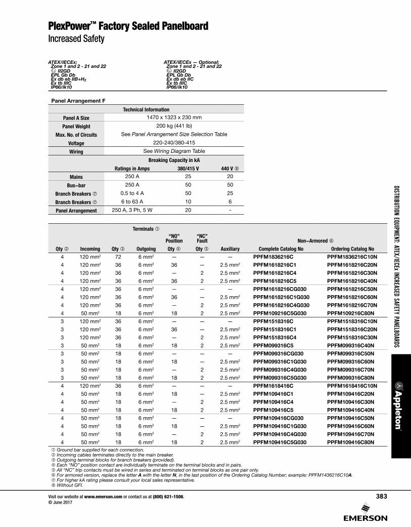
Panel Arrangement F
Dimension in Millimeters (Inches)
A 150 (5.91)
B 61 (2.40)
C 70 (2.76)D 147 (5.79)
Left Internal View Front Internal View Right Internal View Top Internal View
Breaker Curve C30mA
GFI
Branch BreakersCircuit
Breaker Qty
Main Breaker
Size
Armored Entries Non-Armored EntriesArmored Auxilary,
Qty 1
Non- Armored Auxilary,
Qty 1
1 Position Contact
“NO”
1 Trip Contact
“NC”
IncomingSize, Qty 1
Outgoing IncomingSize
Outgoing
Qty Size Qty Size, Qty 12-Poles 16 Amp — — — 36 4 x 250 Amp M63 36 M20 M63 36 M20 — —
2-Poles 16 Amp — X — 18 4 x 200 Amp M63 18 M20 M63 18 M20 M32 M40
2-Poles 16 Amp — — X 18 4 x 200 Amp M63 18 M20 M63 18 M20 M20 M25
2-Poles 16 Amp — X X 18 4 x 200 Amp M63 18 M20 M63 18 M20 M32 M40
2-Poles 16 Amp X — — 18 4 x 200 Amp M63 18 M20 M63 18 M20 — —
2-Poles 16 Amp X X — 18 4 x 200 Amp M63 18 M20 M63 18 M20 M32 M40
2-Poles 16 Amp X — X 18 4 x 200 Amp M63 18 M20 M63 18 M20 M20 M25
2-Poles 16 Amp X X X 9 4 x 100 Amp M40 9 M20 M40 9 M20 M32 M25
3-Poles 16 Amp — — — 18 3 x 200 Amp M63 18 M20 M63 18 M20 — —
3-Poles 16 Amp — X — 18 3 x 200 Amp M63 18 M20 M63 18 M20 M32 M40
3-Poles 16 Amp — — X 18 3 x 200 Amp M63 18 M20 M63 18 M20 M20 M25
3-Poles 16 Amp — X X 9 3 x 100 Amp M40 9 M20 M40 9 M20 M32 M25
3-Poles 16 Amp X — — 9 3 x 100 Amp M40 9 M20 M40 9 M20 — —
3-Poles 16 Amp X X — 9 3 x 100 Amp M40 9 M20 M40 9 M20 M25 M25
3-Poles 16 Amp X — X 9 3 x 100 Amp M40 9 M20 M40 9 M20 M20 M25
3-Poles 16 Amp X X X 9 3 x 100 Amp M40 9 M20 M40 9 M20 M32 M25
4-Poles 16 Amp — — — 18 4 x 200 Amp M63 18 M20 M63 18 M20 — —
4-Poles 16 Amp — X — 9 4 x 100 Amp M40 9 M20 M40 9 M20 M25 M25
4-Poles 16 Amp — — X 9 4 x 100 Amp M40 9 M20 M40 9 M20 M20 M25
4-Poles 16 Amp — X X 9 4 x 100 Amp M40 9 M20 M40 9 M20 M32 M25
4-Poles 16 Amp X — — 9 4 x 100 Amp M40 9 M20 M40 9 M20 — —
4-Poles 16 Amp X X — 9 4 x 100 Amp M40 9 M20 M40 9 M20 M25 M25
4-Poles 16 Amp X — X 9 4 x 100 Amp M40 9 M20 M40 9 M20 M20 M25
4-Poles 16 Amp X X X 9 4 x 100 Amp M40 9 M20 M40 9 M20 M32 M25
ATEX/IECEx: Zone 1 and 2 - 21 and 22
II2GD EPL Gb Db Ex db eb IIB+H2 Ex tb IIIC IP66/Ik10
ATEX/IECEx — Optional: Zone 1 and 2 - 21 and 22
II2GD EPL Gb Db Ex db eb IIC Ex tb IIIC IP66/Ik10
PlexPower™ Factory Sealed PanelboardIncreased Safety
Panel Arrangement F
Technical Information
Panel A Size 1470 x 1323 x 230 mm
Panel Weight 200 kg (441 lb)
Max. No. of Circuits See Panel Arrangement Size Selection Table
Voltage 220-240/380-415
Wiring See Wiring Diagram Table
Breaking Capacity in kA
Ratings in Amps 380/415 V 440 V
Mains 250 A 25 20
Bus-bar 250 A 50 50
Branch Breakers 0.5 to 4 A 50 25
Branch Breakers 6 to 63 A 10 6
Panel Arrangement 250 A, 3 Ph, 5 W 20 -
Terminals
Non-Armored
Qty Incoming Qty Outgoing
“NO” Position
“NC” Fault
AuxiliaryQty Qty Complete Catalog No Ordering Catalog No4 120 mm2 72 6 mm2 — — — PPFM1836216C PPFM1836216C10N
4 120 mm2 36 6 mm2 36 — 2.5 mm2 PPFM1618216C1 PPFM1618216C20N
4 120 mm2 36 6 mm2 — 2 2.5 mm2 PPFM1618216C4 PPFM1618216C30N
4 120 mm2 36 6 mm2 36 2 2.5 mm2 PPFM1618216C5 PPFM1618216C40N
4 120 mm2 36 6 mm2 — — — PPFM1618216CG030 PPFM1618216C50N
4 120 mm2 36 6 mm2 36 — 2.5 mm2 PPFM1618216C1G030 PPFM1618216C60N
4 120 mm2 36 6 mm2 — 2 2.5 mm2 PPFM1618216C4G030 PPFM1618216C70N
4 50 mm2 18 6 mm2 18 2 2.5 mm2 PPFM109216C5G030 PPFM109216C80N
3 120 mm2 36 6 mm2 — — — PPFM1518316C PPFM1518316C10N
3 120 mm2 36 6 mm2 36 — 2.5 mm2 PPFM1518316C1 PPFM1518316C20N
3 120 mm2 36 6 mm2 — 2 2.5 mm2 PPFM1518316C4 PPFM1518316C30N
3 50 mm2 18 6 mm2 18 2 2.5 mm2 PPFM099316C5 PPFM099316C40N
3 50 mm2 18 6 mm2 — — — PPFM099316CG030 PPFM099316C50N
3 50 mm2 18 6 mm2 18 — 2.5 mm2 PPFM099316C1G030 PPFM099316C60N
3 50 mm2 18 6 mm2 — 2 2.5 mm2 PPFM099316C4G030 PPFM099316C70N
3 50 mm2 18 6 mm2 18 2 2.5 mm2 PPFM099316C5G030 PPFM099316C80N
4 120 mm2 36 6 mm2 — — — PPFM1618416C PPFM1618416C10N
4 50 mm2 18 6 mm2 18 — 2.5 mm2 PPFM109416C1 PPFM109416C20N
4 50 mm2 18 6 mm2 — 2 2.5 mm2 PPFM109416C4 PPFM109416C30N
4 50 mm2 18 6 mm2 18 2 2.5 mm2 PPFM109416C5 PPFM109416C40N
4 50 mm2 18 6 mm2 — — — PPFM109416CG030 PPFM109416C50N
4 50 mm2 18 6 mm2 18 — 2.5 mm2 PPFM109416C1G030 PPFM109416C60N
4 50 mm2 18 6 mm2 — 2 2.5 mm2 PPFM109416C4G030 PPFM109416C70N
4 50 mm2 18 6 mm2 18 2 2.5 mm2 PPFM109416C5G030 PPFM109416C80N Ground bar supplied for each connection. Incoming cables terminates directly to the main breaker. Outgoing terminal blocks for branch breakers (provided). Each “NO” position contact are individually terminate on the terminal blocks and in pairs. All “NC” trip contacts must be wired in series and terminated on terminal blocks as one pair only. For armored version, replace the letter A with the letter N, in the last position of the Ordering Catalog Number; example: PPFM1436216C10A. For higher kA rating please consult your local sales representative. Without GFI.

DIST
RIBU
TION
EQUI
PMEN
T: AT
EX/I
ECEx
INCR
EASE
D SA
FETY
PAN
ELBO
ARDS
Visit our website at www.emerson.com or contact us at (800) 621-1506. © June 2017
384
ATEX/IECEx: Zone 1 and 2 - 21 and 22
II2GD EPL Gb Db Ex db eb IIB+H2 Ex tb IIIC IP66/Ik10
ATEX/IECEx — Optional: Zone 1 and 2 - 21 and 22
II2GD EPL Gb Db Ex db eb IIC Ex tb IIIC IP66/Ik10
PlexPower™ Factory Sealed PanelboardIncreased Safety
Wiring Diagrams — Panel Arrangements B, C, D, E, F — For Panel Arrangement A, Remove Main Breaker from Wiring Diagrams
Q1: Main BreakerM1-M8: Module Housing
D1-: MCB
2-Pole
2-Pole + GFI
2-Pole + GFI + AUX NO + AUX NC
Number of branch circuit breakers will depend on the number of module housing.

DISTRIBUTION EQUIPMENT: ATEX/IECEx INCREASED SAFETY PANELBOARDS
Visit our website at www.emerson.com or contact us at (800) 621-1506. © June 2017
385
ATEX/IECEx: Zone 1 and 2 - 21 and 22
II2GD EPL Gb Db Ex db eb IIB+H2 Ex tb IIIC IP66/Ik10
ATEX/IECEx — Optional: Zone 1 and 2 - 21 and 22
II2GD EPL Gb Db Ex db eb IIC Ex tb IIIC IP66/Ik10
Standard Panel Arrangement Layout — Dimensions in Millimeters (Inches)
Panel Arrangement A
Panel Arrangement B
PlexPower™ Factory Sealed PanelboardIncreased Safety

DIST
RIBU
TION
EQUI
PMEN
T: AT
EX/I
ECEx
INCR
EASE
D SA
FETY
PAN
ELBO
ARDS
Visit our website at www.emerson.com or contact us at (800) 621-1506. © June 2017
386
ATEX/IECEx: Zone 1 and 2 - 21 and 22
II2GD EPL Gb Db Ex db eb IIB+H2 Ex tb IIIC IP66/Ik10
ATEX/IECEx — Optional: Zone 1 and 2 - 21 and 22
II2GD EPL Gb Db Ex db eb IIC Ex tb IIIC IP66/Ik10
PlexPower™ Factory Sealed PanelboardIncreased Safety
Standard Panel Arrangement Layout — Dimensions in Millimeters (Inches)
Panel Arrangement C
Panel Arrangement D

DISTRIBUTION EQUIPMENT: ATEX/IECEx INCREASED SAFETY PANELBOARDS
Visit our website at www.emerson.com or contact us at (800) 621-1506. © June 2017
387
ATEX/IECEx: Zone 1 and 2 - 21 and 22
II2GD EPL Gb Db Ex db eb IIB+H2 Ex tb IIIC IP66/Ik10
ATEX/IECEx — Optional: Zone 1 and 2 - 21 and 22
II2GD EPL Gb Db Ex db eb IIC Ex tb IIIC IP66/Ik10
Standard Panel Arrangement Layout — Dimensions in Millimeters (Inches)
Panel Arrangement E
Panel Arrangement F
PlexPower™ Factory Sealed PanelboardIncreased Safety