Siemens STEP 2000 Course · Branch-Circuit Panelboard appliance branch-circuit panelboard and a...
31
Siemens STEP 2000 Course Panelboards It's easy to get in STEP! Download any course. Hint: Make sure you download all parts for each course and the test answer form. Complete each chapter and its review section Print the test answer form, take the final exam and fill in the form. Hint: The final exam is always at the end of the last part. Send your test answer form to EandM for grading. If you achieve a score of 70% or better, we'll send you a certificate of completion! If you have any questions, contact EandM Training at 866.693.2636 or fax 707.473.3190 or [email protected] . Need more information? Contact EandM at 866.693.2636 or fax 707.473.3190 or [email protected] for product information, quotes, classroom training courses and more. STEP 2000 Courses distributed by www.eandm.com
Transcript of Siemens STEP 2000 Course · Branch-Circuit Panelboard appliance branch-circuit panelboard and a...
Siemens STEP 2000 Course
Panelboards
It's easy to get in STEP!
Download any course. Hint: Make sure you download all parts for each course and the test answer form.
Complete each chapter and its review section Print the test answer form, take the final exam and fill in the form.
Hint: The final exam is always at the end of the last part. Send your test answer form to EandM for grading. If you achieve a score of 70% or better, we'll
send you a certificate of completion! If you have any questions, contact EandM Training at 866.693.2636 or fax 707.473.3190 or [email protected].
Need more information? Contact EandM at 866.693.2636
or fax 707.473.3190 or [email protected]
for product information, quotes, classroom training courses and more.
STEP 2000 Courses distributed by www.eandm.com
1
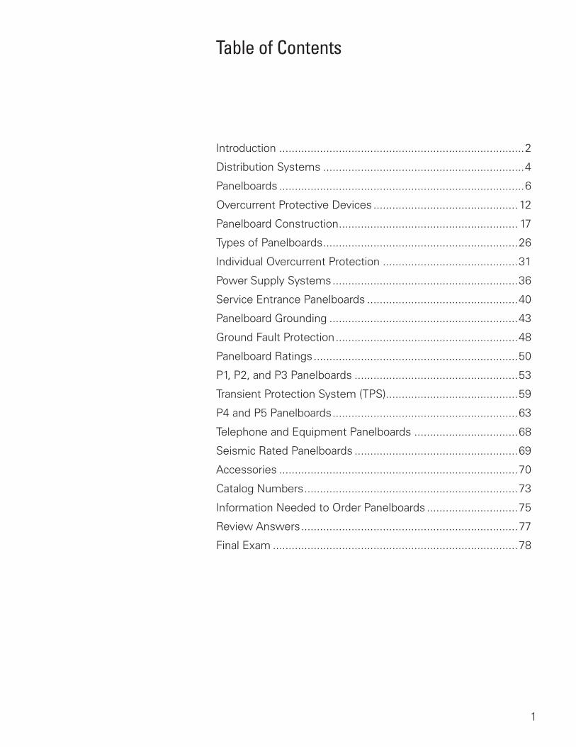
Table of Contents
Introduction ..............................................................................2
Distribution Systems ................................................................4
Panelboards ..............................................................................6
Overcurrent Protective Devices ..............................................12
Panelboard Construction ......................................................... 17
Types of Panelboards ..............................................................26
Individual Overcurrent Protection ...........................................31
Power Supply Systems ...........................................................36
Service Entrance Panelboards ................................................40
Panelboard Grounding ............................................................43
Ground Fault Protection ..........................................................48
Panelboard Ratings .................................................................50
P1, P2, and P3 Panelboards ....................................................53
Transient Protection System (TPS) ..........................................59
P4 and P5 Panelboards ...........................................................63
Telephone and Equipment Panelboards .................................68
Seismic Rated Panelboards ....................................................69
Accessories ............................................................................70
Catalog Numbers ....................................................................73
Information Needed to Order Panelboards .............................75
Review Answers .....................................................................77
Final Exam ..............................................................................78
2
Introduction
Welcome to another course in the STEP series, Siemens Technical Education Program, designed to prepare our distributors to sell Siemens Energy & Automation products more effectively. This course covers Panelboards and related products.
Upon completion of Panelboards you will be able to:
• Explain the role of panelboards in a distribution system
• Define a panelboard according to the National Electrical Code®
• Distinguish between a lighting and appliance panelboard versus a power and distribution panelboard
• Explain the need for circuit protection
• Identify various components of a Siemens panelboard
• Distinguish between a main breaker and main lug only panelboard
• Identify various power supply systems
• Explain the use of panelboards used as service-entrance equipment
• Describe the proper grounding techniques of service entrance and downstream panelboards
• Identify various ratings of Siemens panelboards
• Identify panelboard accessories
3
This knowledge will help you better understand customer applications. In addition, you will be able to describe products to customers and determine important differences between products. You should complete Basics of Electricity and Molded Case Circuit Breakers before attempting Panelboards. An understanding of many of the concepts covered in Basics of Electricity and Molded Case Circuit Breakers is required for Panelboards.
If you are an employee of a Siemens Energy & Automation authorized distributor, fill out the final exam tear-out card and mail in the card. We will mail you a certificate of completion if you score a passing grade. Good luck with your efforts.
I-T-E, Vacu-Break and Clampmatic are registered trademarks of Siemens Energy & Automation, Inc.
Sentron is a trademark of Siemens Energy & Automation, Inc.
National Electrical Code® and NEC® are registered trademarks of the National Fire Protection Association, Quincy, MA 02269. Portions of the National Electrical Code are reprinted with permission from NFPA 70-2005, National Electrical Code Copyright, 2004, National Fire Protection Association, Quincy, MA 02269. This reprinted material is not the complete and official position of the National Fire Protection Association on the referenced subject which is represented by the standard in its entirety.
Underwriters Laboratories Inc. is a registered trademark of Underwriters Laboratories Inc., Northbrook, IL 60062. The abbreviation “UL” shall be understood to mean Underwriters Laboratories Inc.
Other trademarks are the property of their respective owners.
4
Distribution Systems
A distribution system is a system that distributes electrical power throughout a building. Distribution systems are used in every residential, commercial, and industrial building.
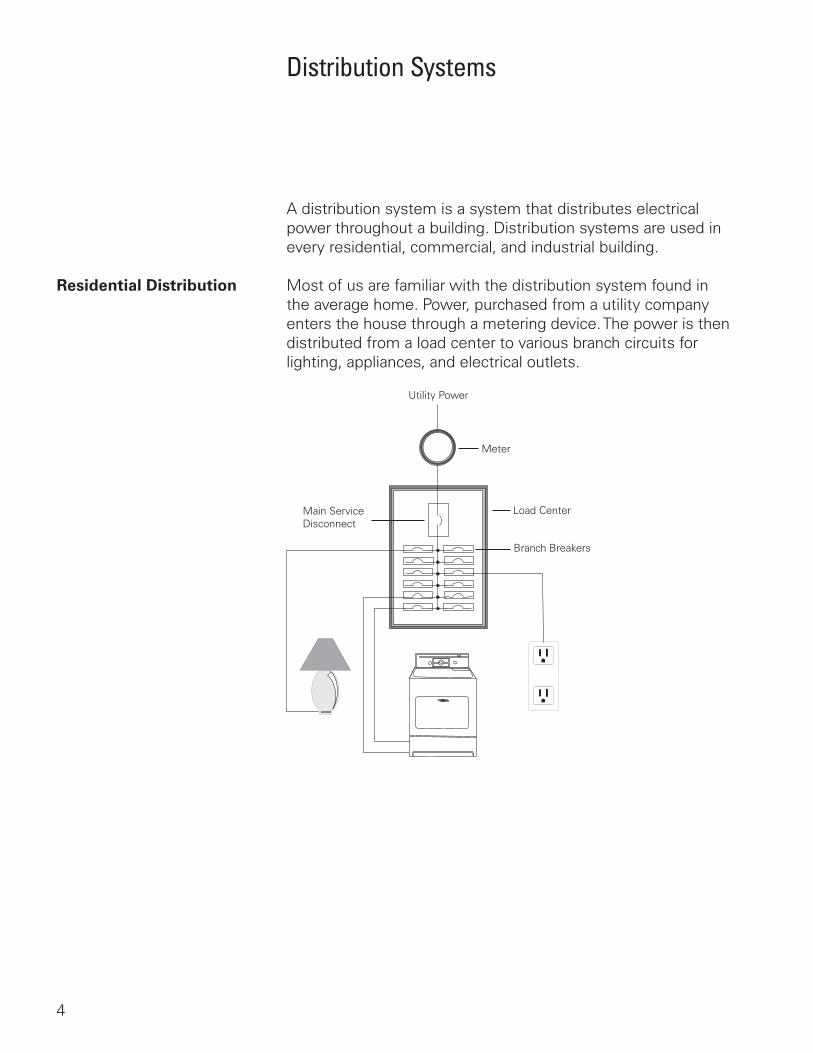
Residential Distribution Most of us are familiar with the distribution system found in the average home. Power, purchased from a utility company enters the house through a metering device. The power is then distributed from a load center to various branch circuits for lighting, appliances, and electrical outlets.
Utility Power
Meter
Load CenterMain ServiceDisconnect
Branch Breakers
5
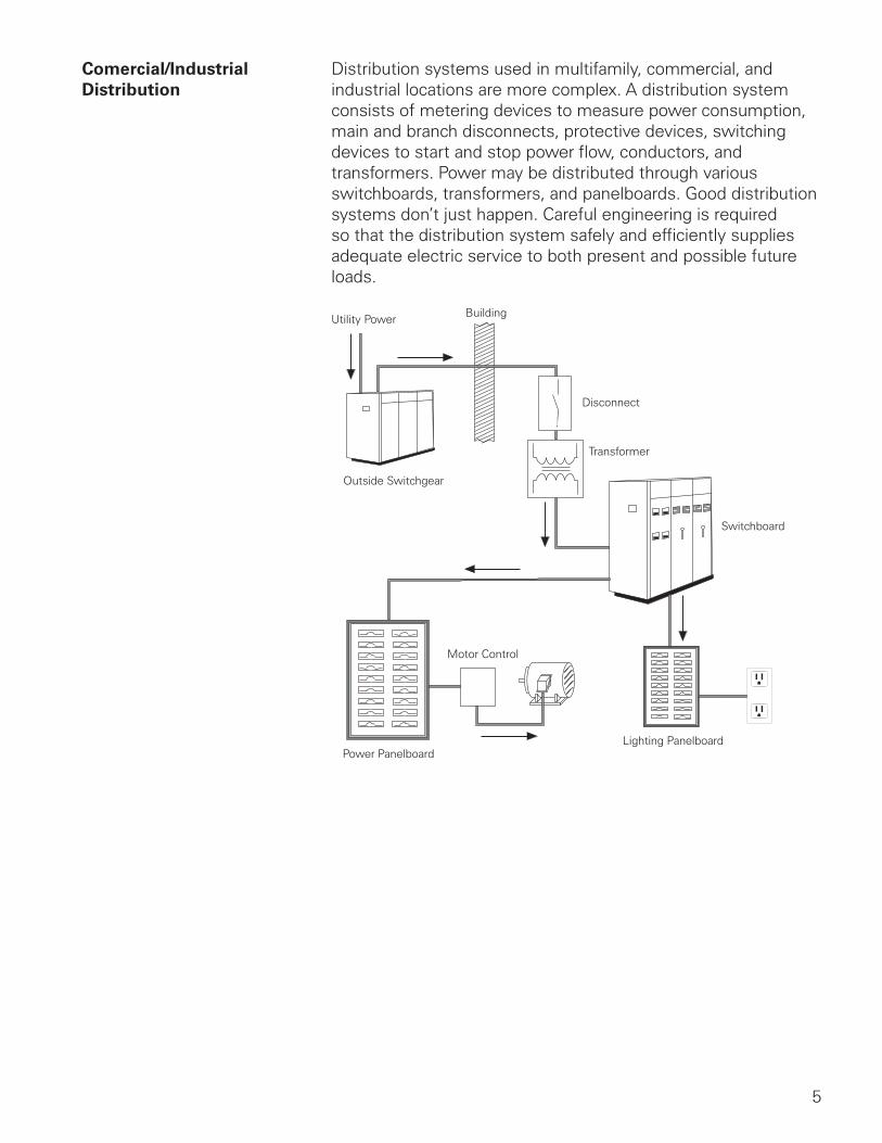
Comercial/Industrial Distribution systems used in multifamily, commercial, and Distribution industrial locations are more complex. A distribution system
consists of metering devices to measure power consumption, main and branch disconnects, protective devices, switching devices to start and stop power flow, conductors, and transformers. Power may be distributed through various switchboards, transformers, and panelboards. Good distribution systems don’t just happen. Careful engineering is required so that the distribution system safely and efficiently supplies adequate electric service to both present and possible future loads.
Utility Power Building
Outside Switchgear
Disconnect
Transformer
Switchboard
Motor Control
Power PanelboardLighting Panelboard
6
Panelboards
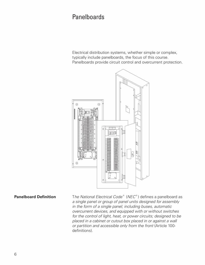
Electrical distribution systems, whether simple or complex, typically include panelboards, the focus of this course. Panelboards provide circuit control and overcurrent protection.
Panelboard Definition The National Electrical Code® (NEC®) defines a panelboard as a single panel or group of panel units designed for assembly in the form of a single panel; including buses, automatic overcurrent devices, and equipped with or without switches for the control of light, heat, or power circuits; designed to be placed in a cabinet or cutout box placed in or against a wall or partition and accessible only from the front (Article 100-definitions).
7
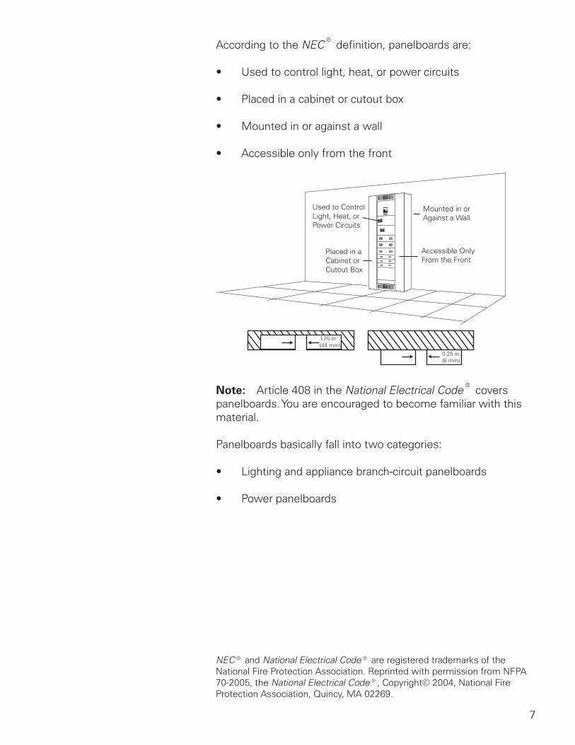
According to the NEC® definition, panelboards are:
• Used to control light, heat, or power circuits
• Placed in a cabinet or cutout box
• Mounted in or against a wall
• Accessible only from the front
Used to ControlLight, Heat, orPower Circuits
Mounted in orAgainst a Wall
Placed in aCabinet orCutout Box
Accessible OnlyFrom the Front
1.75 in.(44 mm)
0.25 in.(6 mm)
Note: Article 408 in the National Electrical Code® covers panelboards. You are encouraged to become familiar with this material.
Panelboards basically fall into two categories:
• Lighting and appliance branch-circuit panelboards
• Power panelboards
NEC® and National Electrical Code® are registered trademarks of the National Fire Protection Association. Reprinted with permission from NFPA 70-2005, the National Electrical Code®, Copyright© 2004, National Fire Protection Association, Quincy, MA 02269.
8
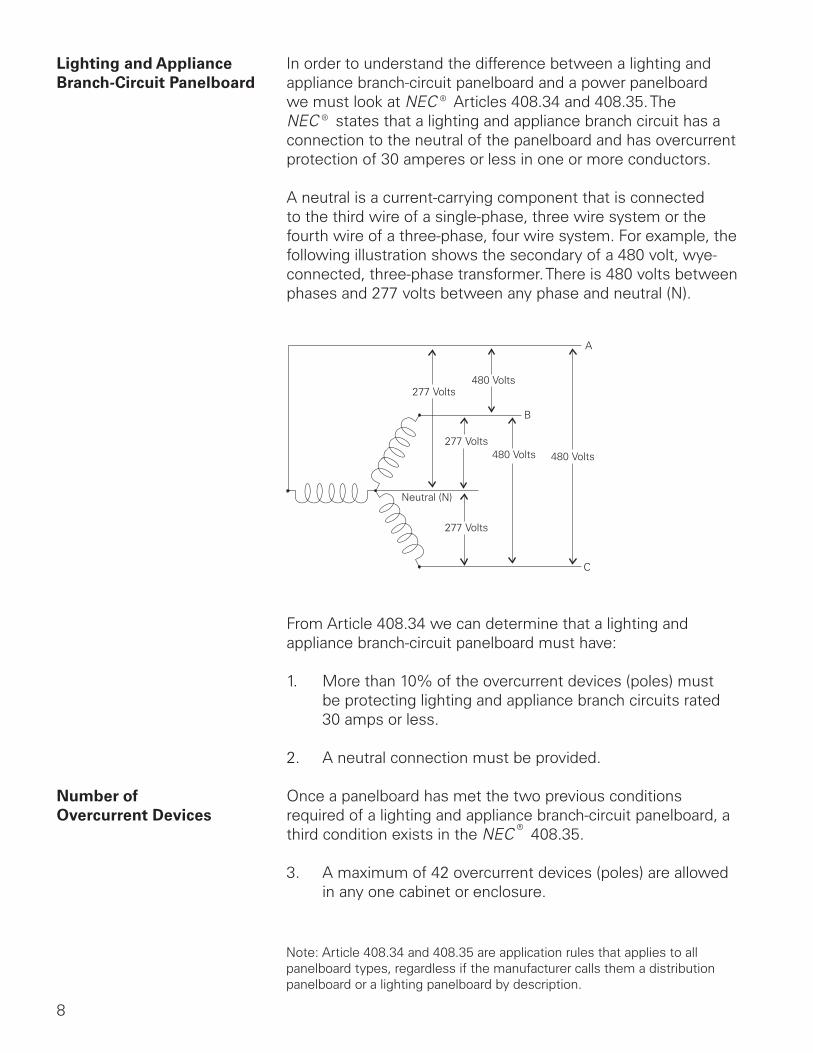
Lighting and Appliance In order to understand the difference between a lighting andBranch-Circuit Panelboard appliance branch-circuit panelboard and a power panelboard
we must look at NEC® Articles 408.34 and 408.35. The NEC® states that a lighting and appliance branch circuit has a connection to the neutral of the panelboard and has overcurrent protection of 30 amperes or less in one or more conductors.
A neutral is a current-carrying component that is connected to the third wire of a single-phase, three wire system or the fourth wire of a three-phase, four wire system. For example, the following illustration shows the secondary of a 480 volt, wye-connected, three-phase transformer. There is 480 volts between phases and 277 volts between any phase and neutral (N).
277 Volts480 Volts
480 Volts480 Volts277 Volts
277 Volts
A
B
C
Neutral (N)
From Article 408.34 we can determine that a lighting and appliance branch-circuit panelboard must have:
1. More than 10% of the overcurrent devices (poles) must be protecting lighting and appliance branch circuits rated 30 amps or less.
2. A neutral connection must be provided.
Number of Once a panelboard has met the two previous conditionsOvercurrent Devices required of a lighting and appliance branch-circuit panelboard, a
third condition exists in the NEC® 408.35.
3. A maximum of 42 overcurrent devices (poles) are allowed in any one cabinet or enclosure.
Note: Article 408.34 and 408.35 are application rules that applies to all panelboard types, regardless if the manufacturer calls them a distribution panelboard or a lighting panelboard by description.
9
Class CTL In addition to the 42 overcurrent device rule, Article 408.15 states that a lighting and appliance branch-circuit panelboard shall be provided with physical means to prevent the installation of more overcurrent devices than that number for which the panelboard was designed, rated, and approved.
Class CTL is a designation used by Underwriters Laboratories, Inc. (UL 67), to designate panelboards and circuit protection devices which meet the NEC® code. Class CTL panelboards, such as Siemens P1, P2, and P3 panelboards, incorporate physical means that prevent the installation of more overcurrent devices than the panelboard is designed and rated.
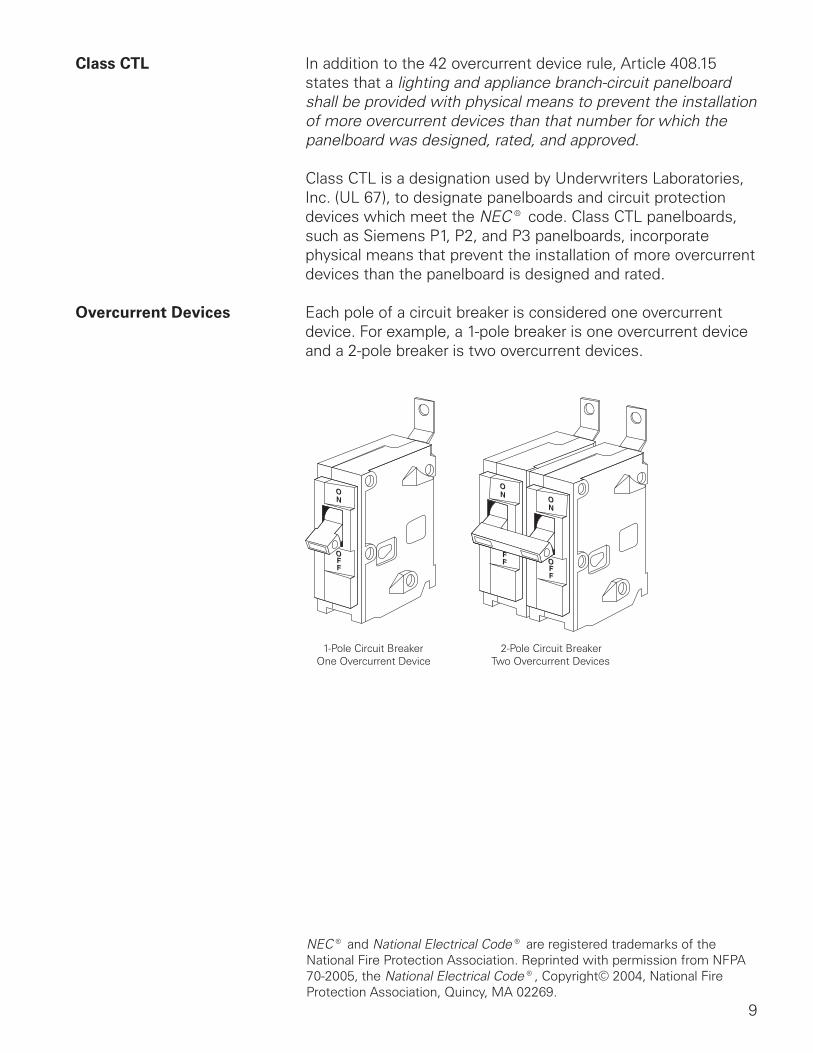
Overcurrent Devices Each pole of a circuit breaker is considered one overcurrent device. For example, a 1-pole breaker is one overcurrent device and a 2-pole breaker is two overcurrent devices.
1-Pole Circuit BreakerOne Overcurrent Device
2-Pole Circuit BreakerTwo Overcurrent Devices
NEC® and National Electrical Code® are registered trademarks of the National Fire Protection Association. Reprinted with permission from NFPA 70-2005, the National Electrical Code®, Copyright© 2004, National Fire Protection Association, Quincy, MA 02269.
10
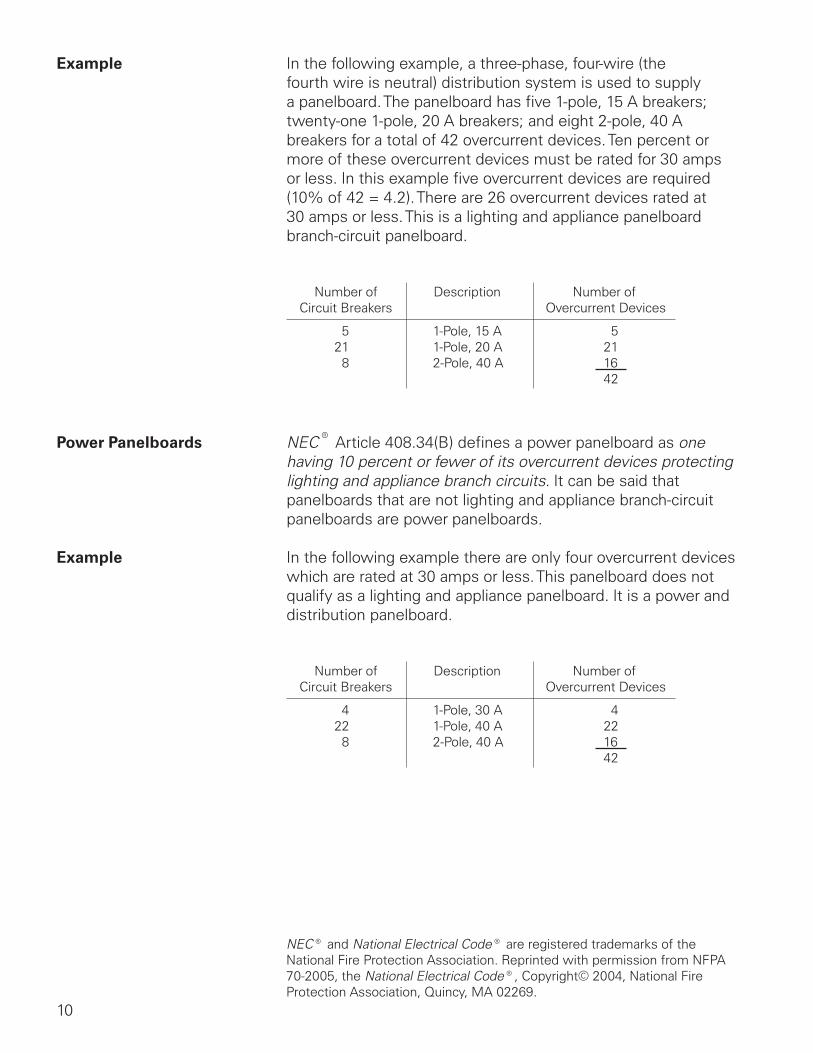
Example In the following example, a three-phase, four-wire (the fourth wire is neutral) distribution system is used to supply a panelboard. The panelboard has five 1-pole, 15 A breakers; twenty-one 1-pole, 20 A breakers; and eight 2-pole, 40 A breakers for a total of 42 overcurrent devices. Ten percent or more of these overcurrent devices must be rated for 30 amps or less. In this example five overcurrent devices are required (10% of 42 = 4.2). There are 26 overcurrent devices rated at 30 amps or less. This is a lighting and appliance panelboard branch-circuit panelboard.
Number ofCircuit Breakers
521
8
Description
1-Pole, 15 A1-Pole, 20 A2-Pole, 40 A
Number of Overcurrent Devices
5211642
Power Panelboards NEC® Article 408.34(B) defines a power panelboard as one having 10 percent or fewer of its overcurrent devices protecting lighting and appliance branch circuits. It can be said that panelboards that are not lighting and appliance branch-circuit panelboards are power panelboards.
Example In the following example there are only four overcurrent devices which are rated at 30 amps or less. This panelboard does not qualify as a lighting and appliance panelboard. It is a power and distribution panelboard.
Number ofCircuit Breakers
422
8
Description
1-Pole, 30 A1-Pole, 40 A2-Pole, 40 A
Number of Overcurrent Devices
4221642
NEC® and National Electrical Code® are registered trademarks of the National Fire Protection Association. Reprinted with permission from NFPA 70-2005, the National Electrical Code®, Copyright© 2004, National Fire Protection Association, Quincy, MA 02269.
11
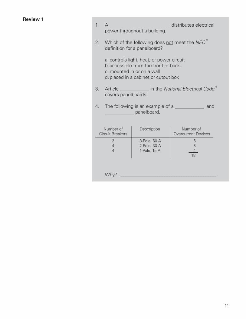
Review 11. A ____________ ____________ distributes electrical
power throughout a building.
2. Which of the following does not meet the NEC® definition for a panelboard?
a. controls light, heat, or power circuit b. accessible from the front or back c. mounted in or on a wall d. placed in a cabinet or cutout box
3. Article ____________ in the National Electrical Code® covers panelboards.
4. The following is an example of a ____________ and ____________ panelboard.
Number ofCircuit Breakers
244
Description
3-Pole, 60 A2-Pole, 30 A1-Pole, 15 A
Number of Overcurrent Devices
684
18
Why? ________________________________________
12
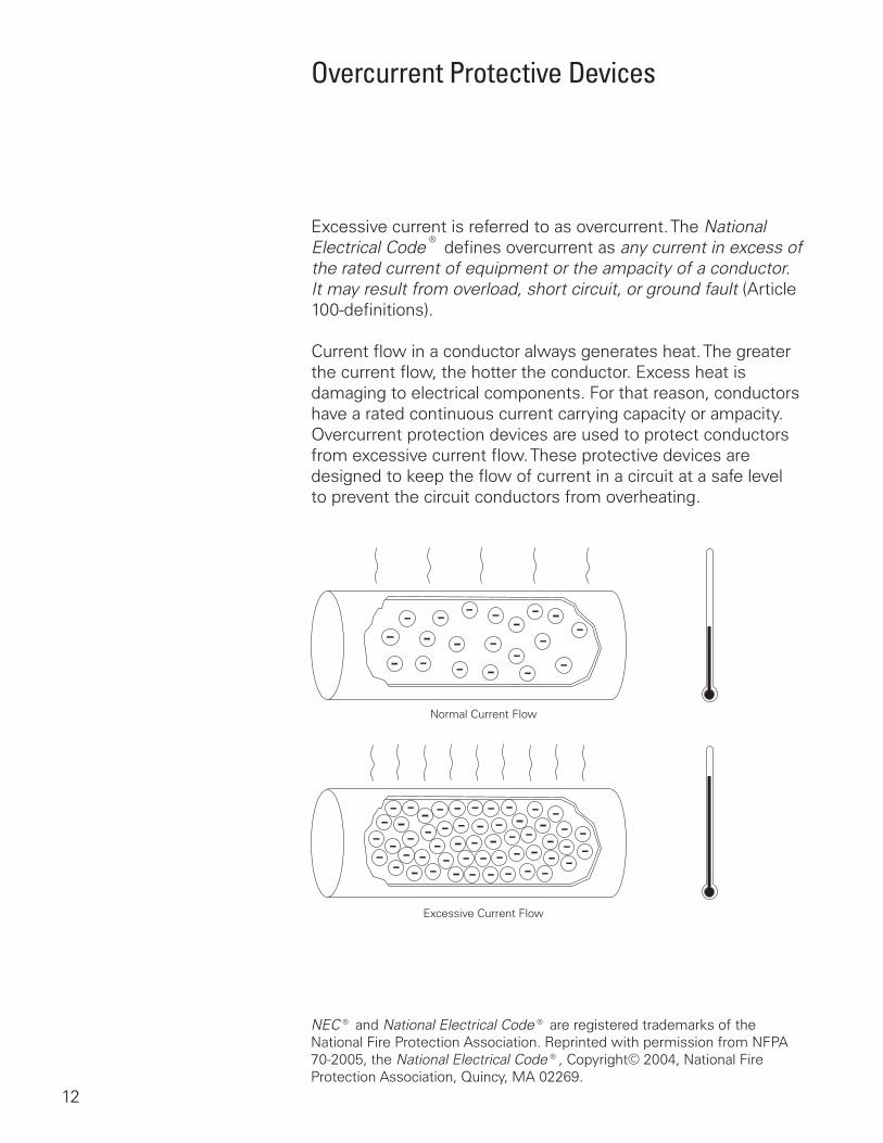
Overcurrent Protective Devices
Excessive current is referred to as overcurrent. The National Electrical Code® defines overcurrent as any current in excess of the rated current of equipment or the ampacity of a conductor. It may result from overload, short circuit, or ground fault (Article 100-definitions).
Current flow in a conductor always generates heat. The greater the current flow, the hotter the conductor. Excess heat is damaging to electrical components. For that reason, conductors have a rated continuous current carrying capacity or ampacity. Overcurrent protection devices are used to protect conductors from excessive current flow. These protective devices are designed to keep the flow of current in a circuit at a safe level to prevent the circuit conductors from overheating.
Normal Current Flow
Excessive Current Flow
NEC® and National Electrical Code® are registered trademarks of the National Fire Protection Association. Reprinted with permission from NFPA 70-2005, the National Electrical Code®, Copyright© 2004, National Fire Protection Association, Quincy, MA 02269.
13
Circuit protection would be unnecessary if overloads and short circuits could be eliminated. Unfortunately, overloads and short circuits do occur. To protect a circuit against these currents, a protective device must determine when a fault condition develops and automatically disconnect the electrical equipment from the voltage source. An overcurrent protection device must be able to recognize the difference between overcurrents and short circuits and respond in the proper way. Slight overcurrents can be allowed to continue for some period of time, but as the current magnitude increases, the protection device must open faster. Short circuits must be interrupted instantly.
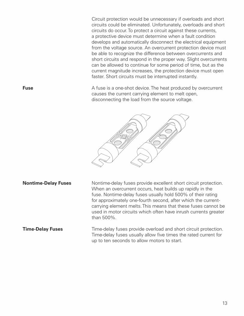
Fuse A fuse is a one-shot device. The heat produced by overcurrent causes the current carrying element to melt open, disconnecting the load from the source voltage.
Nontime-Delay Fuses Nontime-delay fuses provide excellent short circuit protection. When an overcurrent occurs, heat builds up rapidly in the fuse. Nontime-delay fuses usually hold 500% of their rating for approximately one-fourth second, after which the current-carrying element melts. This means that these fuses cannot be used in motor circuits which often have inrush currents greater than 500%.
Time-Delay Fuses Time-delay fuses provide overload and short circuit protection. Time-delay fuses usually allow five times the rated current for up to ten seconds to allow motors to start.

14
Fuse Classes Fuses are grouped into classes based on their operating and construction characteristics. Each class has an ampere interrupting capacity (AIC) which is the amount of fault current they are capable of interrupting without destroying the fuse casing. Fuses are also rated according to the maximum continuous current and maximum voltage they can handle. Underwriters Laboratories (UL) establishes and standardizes basic performance and physical specifications to develop its safety test procedures. These standards have resulted in distinct classes of low voltage fuses rated at 600 volts or less.
Class AIC RatingH 10,000 AK 50,000 AR 200,000 AJ 200,000 AL 200,000 A
Class R Fuseholder An optional Class R fuseholder can be used to prevent any other type of fuse from being used. The Class R rejection clip contains a pin that permits only the notched Class R fuse to be inserted. This prevents a lower rated fuse from being used.
Notch
Pin
Rejection Clip
Fusible Disconnect Switch A fusible disconnect switch is one type of device used on panelboards to provide overcurrent protection. Properly sized fuses located in the switch open when an overcurrent condition exists.
15
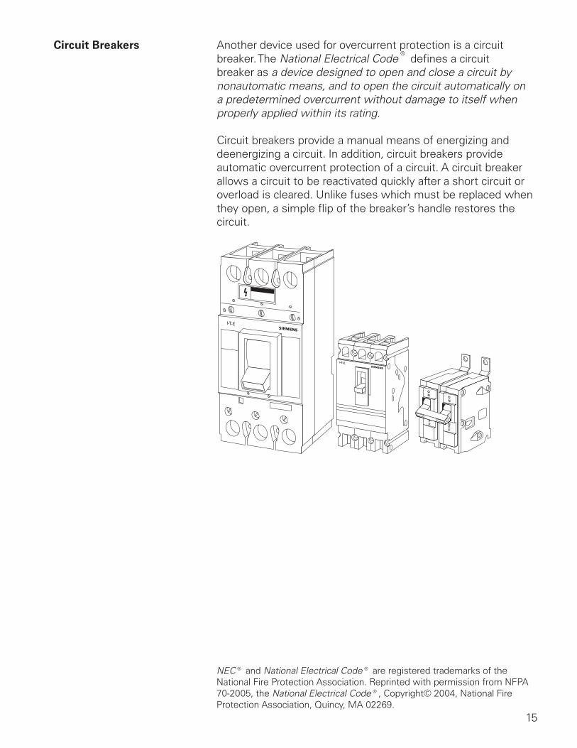
Circuit Breakers Another device used for overcurrent protection is a circuit breaker. The National Electrical Code® defines a circuit breaker as a device designed to open and close a circuit by nonautomatic means, and to open the circuit automatically on a predetermined overcurrent without damage to itself when properly applied within its rating.
Circuit breakers provide a manual means of energizing and deenergizing a circuit. In addition, circuit breakers provide automatic overcurrent protection of a circuit. A circuit breaker allows a circuit to be reactivated quickly after a short circuit or overload is cleared. Unlike fuses which must be replaced when they open, a simple flip of the breaker’s handle restores the circuit.
NEC® and National Electrical Code® are registered trademarks of the National Fire Protection Association. Reprinted with permission from NFPA 70-2005, the National Electrical Code®, Copyright© 2004, National Fire Protection Association, Quincy, MA 02269.
16
Ampere Rating Like fuses, every circuit breaker has a specific ampere, voltage, and fault current interruption rating. The ampere rating is the maximum continuous current a circuit breaker can carry without exceeding its rating. As a general rule, the circuit breaker ampere rating should match the conductor ampere rating. For example, if the conductor is rated for 20 amps, the circuit breaker should be rated for 20 amps. Siemens I-T-E® breakers are rated on the basis of using 60° C or 75° C conductors. This means that even if a conductor with a higher temperature rating were used, the ampacity of the conductor must be figured on its 60° C or 75° C rating.
There are some specific circumstances when the ampere rating is permitted to be greater than the current carrying capacity of the circuit. For example, motor and welder circuits can exceed conductor ampacity to allow for inrush currents and duty cycles within limits established by NEC®. Generally the ampere rating of a circuit breaker is selected at 125% of the continuous load current. This usually corresponds to the conductor ampacity which is also selected at 125% of continuous load current. For example, a 125 amp circuit breaker would be selected for a load of 100 amps.
Voltage Rating The voltage rating of the circuit breaker must be at least equal to the circuit voltage. The voltage rating of a circuit breaker can be higher than the circuit voltage, but never lower. For example, a 480 VAC circuit breaker could be used on a 240 VAC circuit. A 240 VAC circuit breaker could not be used on a 480 VAC circuit. The voltage rating is a function of the circuit breakers ability to suppress the internal arc that occurs when the circuit breaker’s contacts open.
Fault Current Circuit breakers are also rated according to the level of faultInterrupting Rating current they can interrupt. When applying a circuit breaker, one
must be selected which can sustain the largest potential short circuit current which can occur in the selected application. Siemens circuit breakers have interrupting ratings from 10,000 to 200,000 amps. To find the interrupting rating of a specific circuit breaker refer to the Speedfax catalog.
NEC® and National Electrical Code® are registered trademarks of the National Fire Protection Association.
17
Panelboard Construction
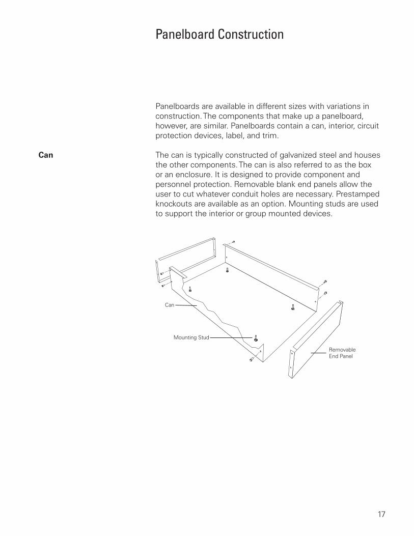
Panelboards are available in different sizes with variations in construction. The components that make up a panelboard, however, are similar. Panelboards contain a can, interior, circuit protection devices, label, and trim.
Can The can is typically constructed of galvanized steel and houses the other components. The can is also referred to as the box or an enclosure. It is designed to provide component and personnel protection. Removable blank end panels allow the user to cut whatever conduit holes are necessary. Prestamped knockouts are available as an option. Mounting studs are used to support the interior or group mounted devices.
Can
Mounting Stud
RemovableEnd Panel
18
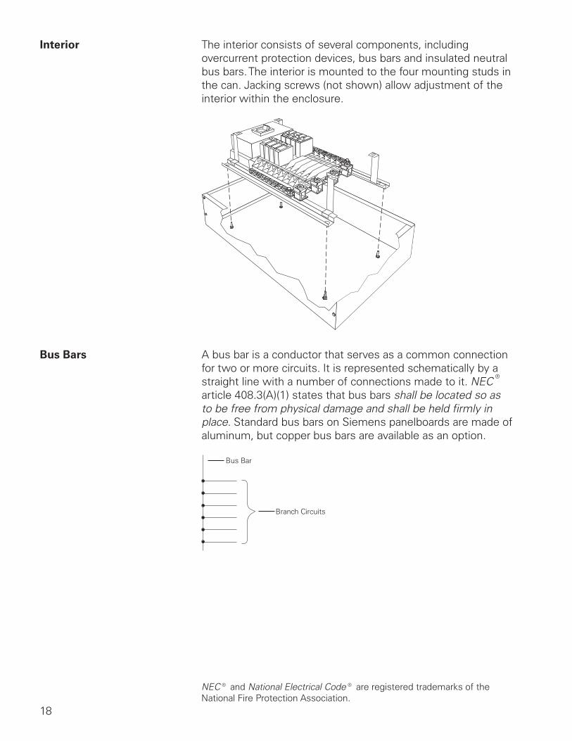
Interior The interior consists of several components, including overcurrent protection devices, bus bars and insulated neutral bus bars. The interior is mounted to the four mounting studs in the can. Jacking screws (not shown) allow adjustment of the interior within the enclosure.
Bus Bars A bus bar is a conductor that serves as a common connection for two or more circuits. It is represented schematically by a straight line with a number of connections made to it. NEC® article 408.3(A)(1) states that bus bars shall be located so as to be free from physical damage and shall be held firmly in place. Standard bus bars on Siemens panelboards are made of aluminum, but copper bus bars are available as an option.
Bus Bar
Branch Circuits
NEC® and National Electrical Code® are registered trademarks of the National Fire Protection Association.
19
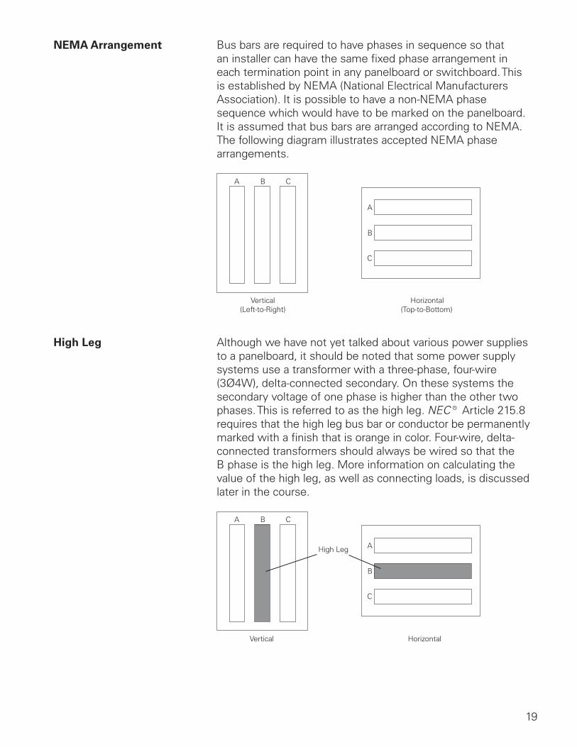
NEMA Arrangement Bus bars are required to have phases in sequence so that an installer can have the same fixed phase arrangement in each termination point in any panelboard or switchboard. This is established by NEMA (National Electrical Manufacturers Association). It is possible to have a non-NEMA phase sequence which would have to be marked on the panelboard. It is assumed that bus bars are arranged according to NEMA. The following diagram illustrates accepted NEMA phase arrangements.
Vertical(Left-to-Right)
Horizontal(Top-to-Bottom)
High Leg Although we have not yet talked about various power supplies to a panelboard, it should be noted that some power supply systems use a transformer with a three-phase, four-wire (3Ø4W), delta-connected secondary. On these systems the secondary voltage of one phase is higher than the other two phases. This is referred to as the high leg. NEC® Article 215.8 requires that the high leg bus bar or conductor be permanently marked with a finish that is orange in color. Four-wire, delta-connected transformers should always be wired so that the B phase is the high leg. More information on calculating the value of the high leg, as well as connecting loads, is discussed later in the course.
Vertical Horizontal
High Leg
20
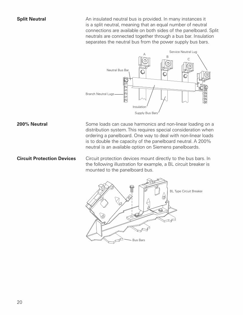
Split Neutral An insulated neutral bus is provided. In many instances it is a split neutral, meaning that an equal number of neutral connections are available on both sides of the panelboard. Split neutrals are connected together through a bus bar. Insulation separates the neutral bus from the power supply bus bars.
Branch Neutral Lugs
Neutral Bus Bar
Insulation
Supply Bus Bars
Service Neutral Lug
200% Neutral Some loads can cause harmonics and non-linear loading on a distribution system. This requires special consideration when ordering a panelboard. One way to deal with non-linear loads is to double the capacity of the panelboard neutral. A 200% neutral is an available option on Siemens panelboards.
Circuit Protection Devices Circuit protection devices mount directly to the bus bars. In the following illustration for example, a BL circuit breaker is mounted to the panelboard bus.
Bus Bars
BL Type Circuit Breaker
21
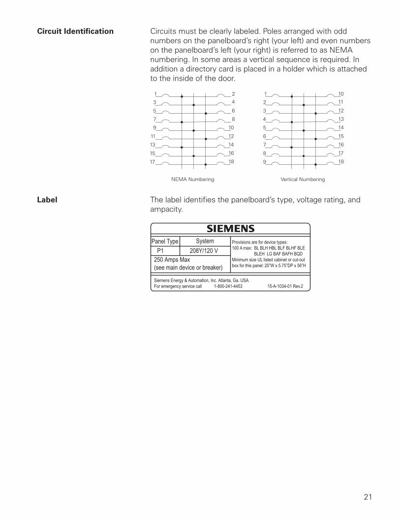
Circuit Identification Circuits must be clearly labeled. Poles arranged with odd numbers on the panelboard’s right (your left) and even numbers on the panelboard’s left (your right) is referred to as NEMA numbering. In some areas a vertical sequence is required. In addition a directory card is placed in a holder which is attached to the inside of the door.
NEMA Numbering Vertical Numbering
Label The label identifies the panelboard’s type, voltage rating, and ampacity.
Panel Type SystemP1 208Y/120 V
Provisions are for device types:100 A max: BL BLH HBL BLF BLHF BLE BLEH LG BAF BAFH BQDMinimum size UL listed cabinet or cut-outbox for this panel: 20”W x 5.75”DP x 56”H
250 Amps Max(see main device or breaker)
Siemens Energy & Automation, Inc. Atlanta, Ga. USAFor emergency service call 1-800-241-4453 15-A-1034-01 Rev.2
22
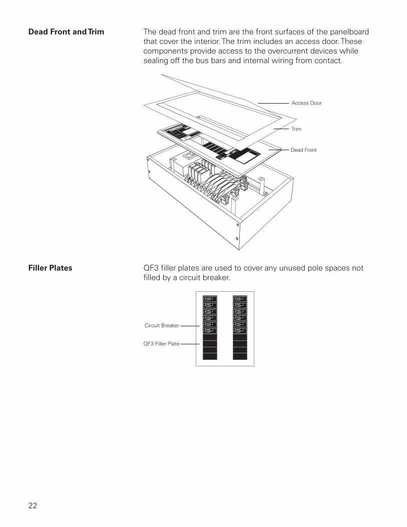
Dead Front and Trim The dead front and trim are the front surfaces of the panelboard that cover the interior. The trim includes an access door. These components provide access to the overcurrent devices while sealing off the bus bars and internal wiring from contact.
Access Door
Trim
Dead Front
Filler Plates QF3 filler plates are used to cover any unused pole spaces not filled by a circuit breaker.
Circuit Breaker
QF3 Filler Plate
23
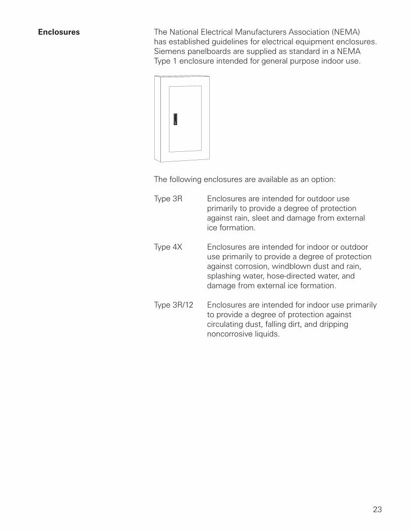
Enclosures The National Electrical Manufacturers Association (NEMA) has established guidelines for electrical equipment enclosures. Siemens panelboards are supplied as standard in a NEMA Type 1 enclosure intended for general purpose indoor use.
The following enclosures are available as an option:
Type 3R Enclosures are intended for outdoor use primarily to provide a degree of protection against rain, sleet and damage from external ice formation.
Type 4X Enclosures are intended for indoor or outdoor use primarily to provide a degree of protection against corrosion, windblown dust and rain, splashing water, hose-directed water, and damage from external ice formation.
Type 3R/12 Enclosures are intended for indoor use primarily to provide a degree of protection against circulating dust, falling dirt, and dripping noncorrosive liquids.
24
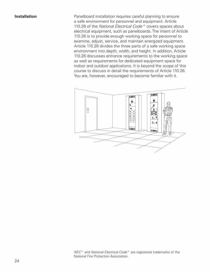
Installation Panelboard installation requires careful planning to ensure a safe environment for personnel and equipment. Article 110.26 of the National Electrical Code® covers spaces about electrical equipment, such as panelboards. The intent of Article 110.26 is to provide enough working space for personnel to examine, adjust, service, and maintain energized equipment. Article 110.26 divides the three parts of a safe working space environment into depth, width, and height. In addition, Article 110.26 discusses entrance requirements to the working space as well as requirements for dedicated equipment space for indoor and outdoor applications. It is beyond the scope of this course to discuss in detail the requirements of Article 110.26. You are, however, encouraged to become familiar with it.
NEC® and National Electrical Code® are registered trademarks of the National Fire Protection Association.
25
Review 2 1. A ____________ is a conductor that serves as a
common connection for two or more circuits.
2. Circuit protection devices are designed to keep the flow of ____________ in a circuit at a safe level to prevent the circuit conductors from overheating.
3. Three causes of overcurrent are:
a. ____________ b. ____________
c. ____________
4. A Class K fuse has an ampere interrupting capacity of ____________ amps.
5. A Class ____________ fuse has a notch to fit a rejection clip.
6. Circuit breakers are rated for continuous ____________ , ______________, and fault current interruption capacity.
7. The panelboard components designed to seal off the bus bars and internal wiring from contact are the ____________ and ____________ .
8. Siemens panelboards are supplied standard in a NEMA Type ____________ enclosure.
26
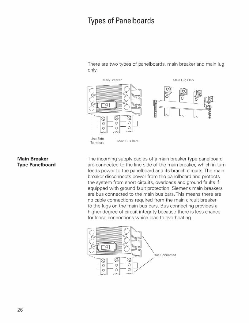
Types of Panelboards
There are two types of panelboards, main breaker and main lug only.
Main Breaker
Main Bus BarsLine SideTerminals
Main Lug Only
Main Breaker The incoming supply cables of a main breaker type panelboard Type Panelboard are connected to the line side of the main breaker, which in turn
feeds power to the panelboard and its branch circuits. The main breaker disconnects power from the panelboard and protects the system from short circuits, overloads and ground faults if equipped with ground fault protection. Siemens main breakers are bus connected to the main bus bars. This means there are no cable connections required from the main circuit breaker to the lugs on the main bus bars. Bus connecting provides a higher degree of circuit integrity because there is less chance for loose connections which lead to overheating.
Bus Connected
27
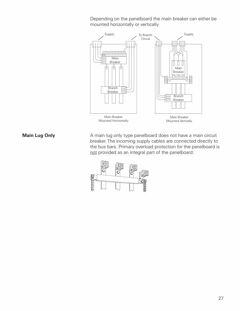
Depending on the panelboard the main breaker can either be mounted horizontally or vertically.
Supply Supply
Main BreakerMounted Horizontally
MainBreaker
MainBreaker
BranchBreaker
BranchBreaker
Main BreakerMounted Vertically
To BranchCircuit
Main Lug Only A main lug only type panelboard does not have a main circuit breaker. The incoming supply cables are connected directly to the bus bars. Primary overload protection for the panelboard is not provided as an integral part of the panelboard.
28
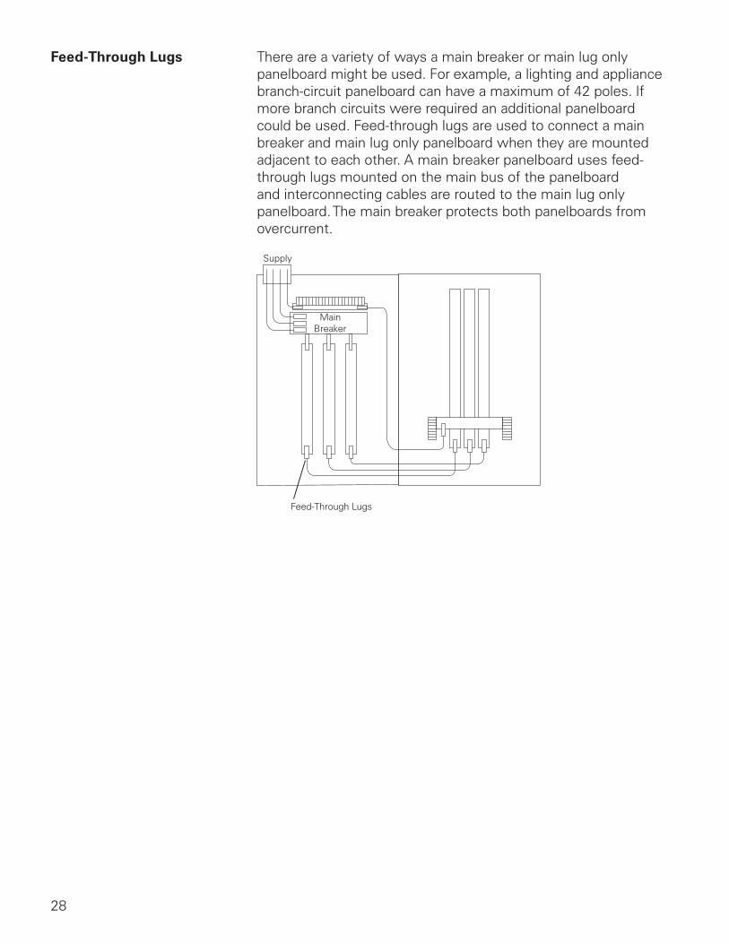
Feed-Through Lugs There are a variety of ways a main breaker or main lug only panelboard might be used. For example, a lighting and appliance branch-circuit panelboard can have a maximum of 42 poles. If more branch circuits were required an additional panelboard could be used. Feed-through lugs are used to connect a main breaker and main lug only panelboard when they are mounted adjacent to each other. A main breaker panelboard uses feed-through lugs mounted on the main bus of the panelboard and interconnecting cables are routed to the main lug only panelboard. The main breaker protects both panelboards from overcurrent.
Supply
MainBreaker
Feed-Through Lugs
29
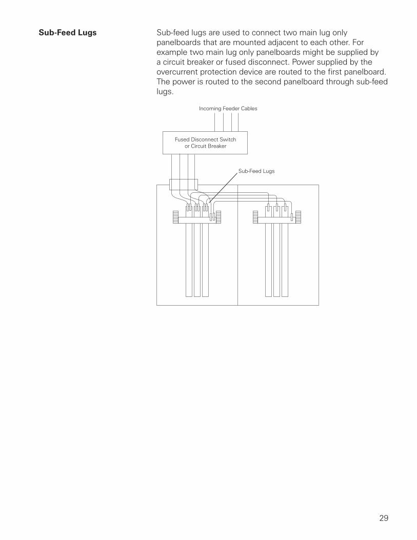
Sub-Feed Lugs Sub-feed lugs are used to connect two main lug only panelboards that are mounted adjacent to each other. For example two main lug only panelboards might be supplied by a circuit breaker or fused disconnect. Power supplied by the overcurrent protection device are routed to the first panelboard. The power is routed to the second panelboard through sub-feed lugs.
Incoming Feeder Cables
Fused Disconnect Switchor Circuit Breaker
Sub-Feed Lugs

30
Unit Space and Unit space is the area that accommodates the branch circuit Number of Circuits breakers in most power panelboards. The number of branch
circuits determines the panel dimensions in lighting and appliance branch-circuit panelboards.
Power PanelboardUnit Space
10”
60”
BranchCircuit Breaker
Unit Space
Lighting and ApplianceBranch-Circuit Panelboards
Number of Circuits
When an application requires a circuit breaker that is a larger frame size than the branch circuit breakers available and will not fit in the branch circuits location, a subfeed breaker can be used. One possible application is to supply a second panelboard located some distance from the first panelboard. This is, however, not the only application. A subfeed breaker can supply any load that a branch circuit breaker can supply.
MainBreaker
Sub-FeedBreaker