PPP-B-576 – Boxes, Wood-Cleated Panelboard - · PDF filePPP-B-576 – Boxes,...
44
PPP-B-576 – Boxes, Wood-Cleated Panelboard Subject/Scope: This specification covers the requirements for wood-cleated panelboard boxes intended for use as containers for domestic and overseas shipment of general materials and supplies, not exceeding 500 pounds for domestic or 400 pounds for overseas shipments (see 6.1). Keywords: Box, cleat, class, type, panel, panelboard, wood, test, fastener, nail, style, strapping, requirement, skid, specification, domestic, joint, overseas, minimum, inspection, fiberboard, dimension, weight, water, specimen, staple, container, content, table, load, area, federal, treatment, cleated, wire, nail, material, surface, style, corrugated, preservative, closure, document, government, mil, conform, group, strap, fire, assembly, loading, block, shipment, specification, commercial, material Published: 12/22/1993 Text in blue boxes such as this one is instructional and is intended to assist you in understanding the document. Text in red boxes such as this explains changes made to the document by The Wooden Crates Organization. Red text has been added to the document or modifies the document since its final version was officially published. Soft Conversion of Imperial to Metric Conversions, when made, consider materials that are available in metric or imperial sizes rather than converting sizes exactly. For example: Panelboard (plywood) in the US is typically 4 feet X 8 feet (1220 x 2440 mm) while panelboard in metric countries is typically 1200 X 2400 mm. Since the standard was developed based on readily available materials these variations in material sizes could not have been practically considered. The content of the document below has not been modified.
Transcript of PPP-B-576 – Boxes, Wood-Cleated Panelboard - · PDF filePPP-B-576 – Boxes,...

PPP-B-576 – Boxes, Wood-Cleated Panelboard
Subject/Scope: This specification covers the requirements for wood-cleated panelboard boxes intended
for use as containers for domestic and overseas shipment of general materials and
supplies, not exceeding 500 pounds for domestic or 400 pounds for overseas shipments
(see 6.1).
Keywords: Box, cleat, class, type, panel, panelboard, wood, test, fastener, nail, style, strapping, requirement, skid,
specification, domestic, joint, overseas, minimum, inspection, fiberboard, dimension, weight, water,
specimen, staple, container, content, table, load, area, federal, treatment, cleated, wire, nail, material,
surface, style, corrugated, preservative, closure, document, government, mil, conform, group, strap, fire,
assembly, loading, block, shipment, specification, commercial, material
Published: 12/22/1993
Text in blue boxes such as this one is instructional and is intended to assist you in understanding the document.
Text in red boxes such as this explains changes made to the document by The Wooden Crates Organization.
Red text has been added to the document or modifies the document since its final version was officially published.
Soft Conversion of Imperial to Metric
Conversions, when made, consider materials that are available in metric or imperial sizes rather than converting
sizes exactly. For example: Panelboard (plywood) in the US is typically 4 feet X 8 feet (1220 x 2440 mm) while
panelboard in metric countries is typically 1200 X 2400 mm. Since the standard was developed based on readily
available materials these variations in material sizes could not have been practically considered.
The content of the document below has not been modified.

INCH-POUND
PPP-B-576CDecember 22, 1993SUPERSEDINGFed. Spec. PPP-B-576BAugust 19, 1966Fed. Spec. PPP-B-591BApril 23, 1971
FEDERAL SPECIFICATION
BOXES, WOOD-CLEATED PANELBOARD
The General Services Administration has authorized the use of this federalspecification, for all federal agencies.
1. SCOPE AND CLASSIFICATION
1.1 Scope. This specification covers the requirements for wood-cleatedpanelboard boxes intended for use as containers for domestic and overseasshipment of general materials and supplies, not exceeding 500 pounds fordomestic or 400 pounds far overseas shipments (see 6.1).
1.2 Classification.
1.2.1 Type. Boxes covered by this specification are identified by thepanelboard material and shall be of the following types as specified (see 6.1and 6.2).
Type I - Veneer paper overlaidType II - Corrugated plasticType III - Corrugated and solid fiberboard
Beneficial comments (recommendations, additions, deletions) and anypertinent data which may be used in improving this document should beaddressed to: U.S. Army Natick Research, Development and EngineeringCenter, Natick, MA 01760-5018 by using the Standardization DocumentImprovement Proposal (DD Form 1426) appearing at the end of this documentor by letter.
AMSC N/A FSC 8115
DISTRIBUTION STATEMENT A. Approved for public release; distribution is unlimited.

PPP-B-576C
1.2.2 Class. Cleated-panel boxes shall be of the following classes asspecified (see 6.2):
Class 1 - DomesticClass 2 - Overseas
1.2.3 Style. Cleated-panel boxes shall be of the following styles asspecified (see figure 1 and 6.2):
Style A - Standard box corner (see fig. 1)Style Al - style A box modified with skids and when specified
(see 6.2) unnailed top panel closure (see figure 1-A)Style B - Interlocking three way corner (see figure 2) Style Cthru K - Limited to Type III Fiberboard box for class domestic
(see figure 1 and 6.2)
1.2.4 Treatment. Boxes shall be provided the following treatment asspecified (see 6.2).
Treatment a. - Without water preservative or fire retardanttreatmentTreatment b. - With water preservative treatmentTreatment c. - With fire retardant treatment
2. APPLICABLE DOCUMENTS
2.1 Government documents. The following documents, of the issues ineffect on the date of invitation for bids or request for proposal, form apart of this specification to the extent specified herein:
Federal Specifications
FF-F-133 - Fasteners, Corrugated Wood Joint, (Saw Edge)
FF-N-105 - Nails, Brads, Staples, and Spikes: Wire Cut andWrought
Federal Standard
FED-STD-123 - Marking for Shipment (Civil Agencies)
(Activities outside the federal Government may obtain copies of federalspecifications, standards, and commercial item descriptions as outlined underGeneral Information in the Index of Federal Specifications, Standards andCommercial Item Descriptions. The Index, which includes cumulative bimonthlysupplements as issued, is for sale on a subscription basis by theSuperintendent of Documents, U.S. Government Printing Office, Washington, DC20402-0001.)

2
FTP-S 37&e
(Single copies of this specification and other Federal specifications andcommercial item descriptions required by activities outside the FederalGovernment for bidding purposes are available without charge from the GeneralServices Administration Business Service Centers, Regional Offices in Boston,MA; New York, NY; Washington, DC; Atlanta, GA; Chicago, IL; Kansas City, MD;Fort Worth, IX; Denver, CO; San Francisco, CA; Los Angeles, CA; and Seattle,WA.)
(Federal Government activities may obtain copies of Federal standardizationdocuments and the Index of Federal Specifications, standards and Commercial[tan Descriptions from established distribution points in their agencies.}
Military Specifications
MIL-L-19140 - Lumber and Plywood Fire-Retardant TreatedMIL-P-83668 - Plastic Board (For Packaging Applications)
Military Standards
MIL-STD-105 - Sampling Procedures and Tables for Inspection byAttributes
MIL-STD-129 - Marking for Shipment and Storage MIL-STD-731 - Quality of Wood Members for Containers and Pallets
(Copies of military specifications and standards required by contractors inconnection with specific procurement functions should be obtained from theprocuring activity or as directed by the contracting officer.)
2.2 Other publications. The following documents form a part of thisspecification to the extent specified herein. Unless a specific issue isidentified, the issue in effect on date of invitation for bids or request forproposal shall apply:
American Society for Testing and Materials (ASTM)
D 996 - Standard Terminology of Packaging and DistributionEnvironments
D 1990 - Standard Practice for Establishing Allowable Propertiesfor Visually Graded Dimensions, Lumber from in GradeTest of Full Size Specimens
D 3951 - Standard Practice for Commercial PackagingD 4727 - Standard Specification for Corrugated and Solid Fiberboard SheetStock (Container Grade) and Cut Shapes
(Application for copies should be addressed to the American Society forTesting and Materials, 1916 Race Street, Philadelphia, PA 19103-1187.)
3
PPP-B-576C
American Plywood Association (APA)
PS1-83 - Construction and Industrial Plywood
(Application for copies should be addressed to the American PlywoodAssociation, 7011 South 19th Street, P.O. Box 11700, Tacoma, WA 98411-0700.)
(Federal Government activities may obtain copies of those non-Governmentdocuments which have been indexed in the Department of Index ofSpecifications and Standards from the DOD Single Stock Point, 700 RobbinsAvenue, Building 4D, Philadelphia, PA 19111-5094.)
3. REQUIREMENTS
3.1 Materials. It is encouraged that recycled material be used whenpractical. All materials used in the manufacture of boxes, either recovered,recycled or virgin shall meet the requirements of this and referenceddocuments. In addition materials shall not affect or be effected by theproduct being packed. Fiberboard panelboard shall have no more than 40percent post consumer recovered material.
3.1.1 Panelboard. Panelboard shall be as specified (see 6.2 and 6.6).
3.1.1.1 Type I veneer paper-overlaid (pov). Panelboard for classes 1 and2 boxes shall be in accordance with MDO of PS-1. The kraft paper faces usedin manufacturing panelboard with veneer core thicknesses up to and including3/16 inch shall be a minimum basis weight of 42 pounds per 1000 square feet.For core thicknesses over 3/16 inch and including 1/4 inch, the kraft paperfaces shall be a minimum basis weight of 69 pounds per 1000 square feet forthickness requirements (see 3.2.1).
3.1.1.2 Type II corrugated plastic. Panelboard shall be polyethylene,containing 1/2 percent ultraviolet (UV) inhibiter and shall conform to MIL-P-83668, type II. The basis weight of the plastic panel shall be 245 to 255pounds per 1000 square feet.
3.1.1.3 Type III corrugated and solid fiberboard. Panelboard shallconform to ASTM D 4727. Class 1 domestic and class 2 overseas single wall(SW), solid (SF) and V board SF shall conform to the requirements of 3.2.1.
3.1.2 Lumber. Lumber shall conform to MIL-STO-731, class 2 for cleats(see 3.2.2) and class 3 for skids (see 3.4) and shall conform tocommercial standards in accordance with ASTM D 1990.
3.1.3 Fasteners.
4
PFP-D-576C
3.1.3.1 Nails, Nails shall be made of steel wire andshall conform to therequirements of FF-N-105 and as specified in 3.2 and 3.3,
3.1.3.2 Staples or wire stitches. Staples or wire stitches shall be madeof steel wire not less than 0.0625 inch diameter (16 gage). The bearingsurface of the crown (the underside) shall be not less than 5/16 inch exceptthat for type III boxes the bearing surface shall be not less than 1/2 inchlong.
3.1.3.3 Single legged fasteners. Single legged fasteners shall be formedautomatically into a nail from sheared off bright, smooth, knurled, orhelically fluted low-carbon steel or medium carbon steel (stiff-stock) minimum15 gage (0.072 inch diameter) wire and driven subsequently by special machineat rapid rate, with sheared-bevel or sheared-square point. The nail length,before driving, shall be a minimum of 1/8 inch longer than the thickness ofthe material being joined. The automatic machine for driving shall beprovided with needle-point knives, J-clinch plate and 1/32 inch counter sink.Single leg fastener shall not be used in joining panel board to cleats.
3.1.3.4 Other fastenings. Other fastenings may be used to the extentspecified under 3.2. Steel wire used for these fasteners shall have adiameter of not less than 0.0625 inch (16 gage). Points of fasteners andshanks shall be determined by the test specified in 4.4.1 for the applicableapplication. The holding power of these fasteners shall be equal to nailsspecified in 3.1.3.1.
3.1.3.5 Corrugated fasteners. Corrugated fasteners shall conform toFF-F-133 and as specified in 3.2.
3.1.4 Wood preservative, water repellent. Water repellent preservativeshall be composed of either a 2 percent copper napthenate or a 3 percent zincnapthenate (M-GARD W 550) or a l.8 percent copper-8-quinolinolate (PQ 56)(see 6.4).
3-2 Fabrication of panels. Panels shall be fabricated by nailing, staplingor gluing panel-board to cleats placed as shown on figures 1, 1A and 4 and asspecified in 3.2.2.
3.2.1 Panelboard. Panelboard material as specified in 3.1.1.1, 3.1.1.2and 3.1.1.3 shall be joined to cleats by fasteners or glue to make a panelfor a box to carry weights of contents as specified in table I and II andherein. Panelboard for one and two piece panels shall be as specified in3.2.1.1, 3.2.1.2 and 3.2.1.3. The weight of contents for type II panel boxesshall not exceed 500 pounds for class 1 nor more than 400 pounds for class 2.Glue shall not be used to secure plastic panelboard to cleats nor veneerpaper overlaid panels to cleats.
j

PPP-B-57SC
TABLE I. Type I veneer paper/overlaid panelboardthickness requirement
Weight ofcontents (pounds)
Class 1 (domestic)minimum thickness (inch)
Class 2 (overseas)minimum thickness (inch)
Exceeding Notexceeding
Type I and IIloads 1/
Type IIIloads 1/
Type I and IIloads 1/
Type IIIloads y
075100150225250300350
75100150225250300350400
0.070.115.115.115.170.170.225.225
0.090.140.140.140.195.195
0.070.115.140.140.170.225.225
0.120.120.180.195.195
1/ Type of load shall be as specified in 6.2 and as specified for use in6.3.
TABLE II. Type III corrugated and solid fiberboard requirements
Weight ofcontents (pounds)
Class 1 (domestic) Class 2 (overseas)
Exceeding Notexceeding
CF D SWgrades 1/
SF Dgrades 1/
SFgrades 1/ 2/
075150200300
75150200300400
200275350350
200275350350500
V3S or V4SV3S or V4SV3S or V4S
1/ As defined in ASTM D 4727 CF or SF (corrugated or solid fiberboard) D(Domestic), SW (Single-Wall), grades as stated.
2/ Overseas (weather-resistant) boxes are limited to Styles A or B and shallnot exceed dimensions of 4 feet in length, 3 feet in width or 3 feet indepth.
6

PHMV57SO
3.2.1.1 One piece and two piece panels. Bottom panels of boxes notexceeding 72 inches in length or 41 inches in width, shall consist of a singlepiece of panelboard. All panels of all style A, Al and B boxes shall consistof one or two pieces of panelboard joined by either lap or butt joint asspecified in 3.2.1.1.1 or 3.2.1.1.2. Each piece of panelboard in two piecepanels, shall be not less than 24 inches in length or width. Panelboardjoints in adjacent panels shall be not closer than 12 inches of being inline with adjacent parallel joints. Adjacent panels shall be designed forassembly with joints running perpendicular to each other.
3.2.1.1.1 Lap joint. The adjacent edges of the two pieces of panelboardshall be lapped not less than 3 inches and fastened by metal stitches,specified in 3.1.3.2, which shall pass through both pieces and be clinched.There shall be not less than two parallel rows of stitches spaced not lessthan 2 inches apart, and the spacing of stitches in each row shall not exceed4 inches. The lap joint of type III, class 1 fiberboard panelboard may befirmly glued together with a water resistant glue bond. The fiberboard lapjoint of panels shall be firmly glued to each other over the entire surfacearea of contact so that when tested in accordance with 4.4.1.2.1, thefiberboard or layer of fiberboard shall remain in contact with not less than75 percent of the contact area of the other piece of fiberboard.
3.2.1.1.2 Butt joint. The adjacent edges of two pieces of panelboardshall be butted at the mid width of a joint cleat specified in a. and b.herein and each piece fastened to the cleat. The fastening panelboard tocleats using metal stitches shall be in accordance with 3.2.1.1.1 passingthrough the fiberboard and into the cleat. When glue is used to secure thepanelboard joint to the cleat, the fiberboard butt joint area shall be gluedover the entire area of surface contact. When tested in 4.4.1.2.1, thefiberboard or layer of fiberboard shall remain in contact with not less than75 percent of the area of contact with the cleat.
3.2.1.1.3 Top panel modification for unnailed closure, style Al. The toppanel of style Al boxes shall be modified by providing through edge cleatsand filler edge cleats on the underside of the panel (see figure LA). Theunderside cleats shall be of the sane width and thickness as required for theouter cleats. Inside through cleats shall be used to reinforce the insidetop edge of ends of the box, and shall be as shown on figure 1A. Theunderside cleats shall be positioned on the panel so the cleat edges fitsnugly within the applicable side and end panels of the box. Intermediate orreinforcing cleats required for the top panel of the style A box are notapplicable for cleating the underside of the top panel.
7

PPP-B-576C
3.2.2 Cleats. Cleats shall be made from wood specified in 3.1.2. Thesize of cleats shall be as specified in tables III, IV and V. Arrangement ofcleats on panels shall be as shown on figures 1, 1A and 4. When assemblingcleats to panelboard, the clearance between the end of each filler orintermediat cleat and through cleat shall be approximately equal. Whenfiller and intermediate cleats are cut or notched as shown on figure 4 forwater drainage, the clear area of the cut or notch shall be adjacent to thepanelboard and end of the filler cleat shall abutt the edge of the throughcleat. Intermediate cleats and additional cleats shall be as specified in3.2.2.1 and 3.2.2.2.
TABLE III. Size of cleats for type I box panels
Weight of contents(pounds)
Class 1 (domestic),size of cleats (inches)
Class 2 (overseas),size of cleats (inches)
Exceeding Notexceeding
minimumwidth
minimumthickness
minimumwidth
minimumthickness
075100150225250300350
75100150225250300350400
1-3/81-3/41-3/41-3/41-3/41-3/41-3/41-3/4
5/85/85/83/43/43/413/1613/16
1-3/41-3/41-3/41-3/41-3/41-3/41-3/4
5/85/83/43/43/413/1613/16
TABLE IV. Size of cleats for type II box panels
Weight of contents(pounds)
Class 1 (domestic),size of cleats (inches)
Class 2 (overseas),size of cleats (inches)
Exceeding Notexceeding
minimumwidth
minimumthickness
minimumwidth
minimumthickness
0100150225250300350400
100150225250300350400500
1-3/41-3/42-5/833333
3/43/43/43/43/43/43/43/4
1-3/42-1/42-5/83333
3/43/43/43/43/43/43/4
8
PPP-B-576CC
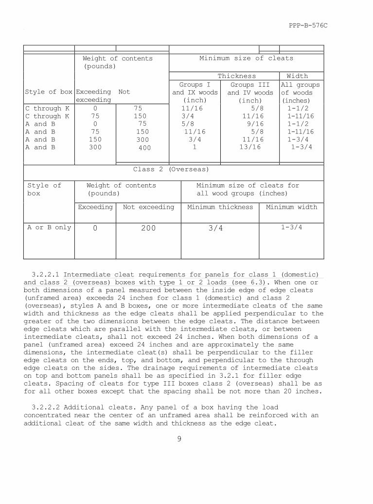
CLASS 1 (DOMESTIC)Weight of contents(pounds)
Minimum size of cleats
Thickness Width
Style of box Exceeding Notexceeding
Groups Iand IX woods
(inch)
Groups IIIand IV woods
(inch)
All groupsof woods(inches)
C through KC through KA and BA and BA and BA and B
075075150300
7515075150300 400
11/163/45/811/163/41
5/811/169/165/8
11/1613/16
1-1/21-11/161-1/21-11/161-3/41-3/4
Class 2 (Overseas)
Style ofbox
Weight of contents(pounds)
Minimum size of cleats forall wood groups (inches)
Exceeding Not exceeding Minimum thickness Minimum width
A or B only 0 200 3/4 1-3/4
3.2.2.1 Intermediate cleat requirements for panels for class 1 (domestic)and class 2 (overseas) boxes with type 1 or 2 loads (see 6.3). When one orboth dimensions of a panel measured between the inside edge of edge cleats(unframed area) exceeds 24 inches for class 1 (domestic) and class 2(overseas), styles A and B boxes, one or more intermediate cleats of the samewidth and thickness as the edge cleats shall be applied perpendicular to thegreater of the two dimensions between the edge cleats. The distance betweenedge cleats which are parallel with the intermediate cleats, or betweenintermediate cleats, shall not exceed 24 inches. When both dimensions of apanel (unframed area) exceed 24 inches and are approximately the samedimensions, the intermediate cleat(s) shall be perpendicular to the filleredge cleats on the ends, top, and bottom, and perpendicular to the throughedge cleats on the sides. The drainage requirements of intermediate cleatson top and bottom panels shall be as specified in 3.2.1 for filler edgecleats. Spacing of cleats for type III boxes class 2 (overseas) shall be asfor all other boxes except that the spacing shall be not more than 20 inches.
3.2.2.2 Additional cleats. Any panel of a box having the loadconcentrated near the center of an unframed area shall be reinforced with anadditional cleat of the same width and thickness as the edge cleat.
9

PPP-B-576C
3.2.2.2.1 Joint cleat for class 1 domestic) boxes. The thickness of eachjoint cleat for class 1 (domestic) boxes shall be the same as the edgecleats. The width of each joint cleat shall be not less than 2-1/4 inches,except if the width of the edge cleat is greater than 2-1/4 inches, the jointcleat shall be the same width as the edge cleat. The length of the jointcleat shall be not less than the distance between edge cleats. The may\mmdeviation shall be minus 1/8 inch.
3.2.2.2.2 Joint cleat for class 2 (overseas) boxes. The thickness of eachjoint cleat shall be as specified for edge cleats and the width shall be notless than 1-1/3 times the required width of the edge cleat, but under nocircumstances shall the width of the cleat be less than 2-1/4 inches.
3.2.3 Fastening of panelboard to cleats. Fasteners for joining panel-board to cleats shall conform to 3.1.3 for nails and 3.1.3.2 for staples andthe sizes specified in table VI. Nails and staples shall be driven throughthe panelboard and into the cleats. Fastener length shall be long enough tobe clinched not less than 1/8 inch. Shiners (protrusion of fastener points)shall not be permitted. Convergent or devergent staples that are of thespecified length (not less than the sum of the thickness of the panelboardand cleat, plus 1/8 inch) normally will not protrude through the cleat do nothave to be clinched. The bearing surface of the fastener shall not be overdriven more than 10 percent of the panelboard thickness. The average spacingof the fasteners lengthwise of the cleat shall be not less than 3 inchesbetween centers (see figure 2). The distance between the nearest edge of anyfastener and the edge of the cleat shall be not less than 3/8 inch (seefigure 2). Also, the distance between the nearest edge of any fastener andthe end of the cleat shall be not less than 3/4 inch or more than 1-1/2inches (see symbol D figure 2 and 3). Fasteners positioned lengthwise of acleat shall be staggered to form two parallel rows approximately 3/8 inchfrom the edges of the cleat (see figure 2).
TABLE VI. Size of Nails and Staples for joining panelboard and cleats
Weight ofcontents(pounds)
Wiregage
Nails Diam. notless than
Inch Head Inch
Staples & otherDiam. not less
Length of allfasteners asspecified
0-150
150-500
15
14
0.072
0.080
13/64 1/
13/64 1/
as specifiedin 3.1.3.2,3.1.3.3, and3.1.3.4 2/
see 3.1.3 1/thru 3.1.3.4 1/
1/ Dimensions of nails for style c thru k of type III boxes shall be not lessthan 1 inch in length and have head diameter of not less than 1/4 inch.
10

PPP-B-576
2/ Staple crown for type III boxes shall be not less than 1/2 inch long,
3.2.3.l Corrugated Fasteners. Corrugated fasteners shall be used forfastening butt joints for type III class 1 (domestic) boxes only. The depthof the fastener shall be not less than 5/8 inch. Alternatively, staples maybe used at the butt joints of all type III box cleats.
3.3 Assembly of boxes. Each box shall be in agreement with figure 1through 5 for the style of box as specified in the contract or order. Panelsof styles A, C, F, H, I, J and K shall be joined with standard box cornersin accordance with figure 2, style A. Panels of style B, D, E, and G shallbe joined with interlocking three-way corners in accordance with figure 3,style B.
3.3.1 Nailing, Each nail fastening the panel board and edge cleat of apanel to the edge cleat of an adjacent panel shall be spaced as specified intable VIII or IX, as applicable, for the thickness of the cleats used (seesymbol identification "S" of box assembly, figures 2 and 3). Boxes assembledwith the box nails specified in 3.1.3.1 shall have approximately 10 percentmore nails than boxes assembled with cooler or sinker nails. When cleatsused are 2-1/4 inches or more in width, two nails shall be driven through thecleat near the end into the side of the appropriate cleat on the abuttingpanel (See figures 2and 3). Wails used in the assembly of boxes shall becement-coated, acid etched, or mechanically deformed (screw type or annular-ring type). Adjacent cleated panels shall be fastened together with coolers,sinkers, corkers or box nails using the nail size and spacing specified intables VIII and DC, as applicable.
TABLE VII. Class 1 (domestic) type I, II and III boxes, size andspacing of nails for fastening together adjacent cleated panels
Cleatsthickness(Inch)
Maximum spacing of nailsfor all wood groups (Inches)
Size of nails (penny) forwood groups 1/
Types I andII loads
Type IIIload
Group Iwood
GroupII wood
GroupIII wood
GroupIV wood
9/16-5/811/32-24/32
3/413/16-1
6553
5443
6778
6777
6777
5667
1/ If the nail protrudes through the last edge cleat or splits cleat, thenthe next smaller size penny nail shall be used.
11

PPP-B-576C
TABLE VIII. Class 2 (overseas) type I, II and III boxes, size andspacing of nails for fastening together adjacent cleated panels
Cleatsthickness(Inch)
Maximum spacing of nailsfar all wood groups (Inches)
Size of nails (penny) forwood groups 1,/
Types I andII loads 2/
Type IIIload 37
Group Iwood
GroupII wood
GroupIII wood
GroupIV wood
3/4 5 4 9 8 7 6
1/ If the nail protrudes through the last edge cleat or splits cleat, thenthe next smaller size penny nail shall be used.
2/ For type of load (see 6.3).
3.3.1.1 Staples, wire stitches, single leg, or other fasteners. Whenstaples, wire stitches, single leg, or other fasteners are used in theassembly of the box, the fasteners shall be tested in accordance with 4.4.1.
3.3.1.2 Fastening ends of cleats (for class 1, domestic). Not less thanone nail shall pass through each end of each overlapping through cleat andinto the side of the appropriate cleat on the adjacent panel. If the weightof the contents of the box exceeds 150 pounds and the cleats are not lessthan 1-7/8 inches in width, not less than two nails shall pass through eachend of each overlapping through cleat and into the side of the appropriatecleat on the adjacent panel, when cleats are group I or II woods; when cleatsare group III or IV woods, one nail only shall be used.
3.3.1.3 Fastening uncleated edges of panel. For boxes of styles c to K,inclusive, the fiberboard along each uncleated edge shall be fastened to thecleat on the adjacent panel by nails passing through the fiberboard and intothe cleat. Nails shall be not less than 1 inch long. The spacing of nailsshall not exceed 3 inches. The head of the nail shall be not less than 1/4inch in diameter.
3.3.2 Dimensions. Boxes shall be furnished having the dimensionsspecified (see 6.2). For the purpose of this specification, dimensions of abox shall be given in the sequence of length, width, depth. The first twodimensions shall be the open face of the box. Unless otherwise specified,dimensions of boxes shall be the inside measurements. A tolerance of +1/8inch shall be permitted in the dimensions.
3.4 Skids. Lumber for skids shall be as specified in 3.1.2. Unlessotherwise specified (see 6.2), each box intended for use with loads having agross weight in excess of 200 pounds or when the box gross weight exceeds
12
PPP-B-576C
1OO pounds and both thelength and width dimensions exceed 48 inches by 24inches respectively, then each box shall be provided with a minimum of twoskids. Additional skids shall be provided when the distance between skids,measured between the inside edges exceeds 48 inches. Additional skids, asrequired, shall be positioned so as to divide the area between the end skidsinto units of equal space. When bolt holes are provided in an end item orequipment, additional skids, if required, shall be located so as to enablethe item to be bolted to the skids. The skids or built up skids and rubbingstrips shall be a minimum of 2-1/2 inches high and 3-1/2 inches wide. Theskids shall be placed parallel to and extend the full width of the box, (theshortest dimension of the bottom of the box) and shall be set not less than2-1/2 inches or more than 1/6 the box length from each end. When skids onlyare used, when specified (see 6.2), a bevel of 45° (+5°) will be applied tothe 3/4 inch portion of the skid ends. When rubbing strips are used inconjunction with skids, the skid ends will not be beveled and the rubbingstrips will be set back from the ends of the skids a distance of 2-1/2 to 4inches to allow for sling placement. When 4-way fork entry is required (see6.2), skids shall be nominal 4x4, placed lengthwise not less than 1-1/2inches nor more than 2-1/2 inches from the container sides and cut out aminimum of 2 inches in depth and of such width as to accommodate forks andslings for handling. When specified (see 6.2), 4-way fork entry shall beaccomplished with built-up skids and rubbing strips having minimum dimensionsof 3-1/2 inches in width and 4 inches in height with the cutouts being notless than 1-1/2 inches in depth. When skids are used, strapping is required.Each skid shall be notched sufficiently to provide clearance for strapping.Filler cleats of the same thickness as the end or side cleats of the bottompanel and not less than the width of the skids shall be provided between eachskid and the bottom panel of the shipping container. Filler cleats shall notbe required for style I boxes. The skids shall be secured to the box bynails conforming to type II, style 18 of FF-N-105, and of such length as topenetrate a minimum of 3/4 the skid thickness. These nails shall notprotrude through the bottom surface of the skid. The nails shall be arrangedin two rows in a staggered pattern, with spacing between nails in each row tobe not more than 6 inches. Each row of nails shall be approximately 1/2 inchfrom the edge of the skid, and the nailing pattern shall begin and endapproximately 1-1/2 inches from the end of each skid and shall not be nailedthrough the strap notch. In addition to the weight requirements specifiedherein, boxes having a width over 40 inches and fitted with rubbing stripskids shall be provided with additional cleats attached to the underside ofthe box (see figure 11). The added cleats are provided to prevent damage tothe floor panel by the tynes of the fork lift.
3.5 Container manufacturer's identification. Unless otherwise specified(see 6.2), each panelboard box shall be marked with the specification number,box type, class, style, box manufacturer's name and address, maximum weightof contents, and type of load. All markings shall be limited to an area of24 square inches and shall be placed in a low corner of a side panel in
13

PPP-B-576C
letters approximately 5/16 inch high, except that the box specificationnumber shall be in letters approximately 3/4 inch high. These markings shallbe arranged in the following pattern as closely as possible:
Fed. spec. PPP-B-576Box type, class and styleBox manufacturer's name and addressMaximum weight of contents (lbs.)Type of loadMod (When required, to designate that the box is in accordance withthe specification requirements except for modification authorized inthe contract or order.)
3.5.1 Preservative identification. The letters "PA" shall be annotated onall class 2 boxes subjected to the PQ56 (c«pper-8-quinolinolate) preservativetreatment in accordance with 3.7. The letters "PB" shall be annotated on allclass 2 boxes subjected to the M-<3ARD W550 (zinc napthenate emulsifiable)preservative treatment in accordance with 3.7.
3.6 Assembly, closure, and strapping of filled boxes. Where thisspecification is referenced as a requirement for the shipping of an item oritems in a contract, order or specification, the requirements of the appendixshall be a mandatory part of this specification.
3.7 Water-repellent treatment. When specified (see 1.2.4 and 6.2) boxesshall have wood cleats treated with a water-repellent preservative specifiedin 3.1.4 applied either by immersion or spray. The preservative shall be dryto touch prior to assembling cleats to the panelboard or painting of thecleats. There shall be evidence of discoloration of the wood cleats whentested in 4.4.2.
3.8 Fire Retardant. When specified (see 1.2.4, 6.2 and 6.5) boxes shallbe constructed of wood treated in accordance with MIL-L-19140.
3.9 Workmanship. No portion of the bearing surface of a fastener shallprotrude above the surface of the panel board or cleat, nor shall it beoverdriven more than 1/32 inch below the surface of the panelboard. Fastenersshall not be visibly deformed except where they are clinched. The panelboardshall be cut square and at no point shall the edge of the panel-board extendmore than 1/16 inch over or 1/4 inch under the panel size as determined bythe cleat assembly. The boxes shall conform to the quality of productestablished by this specification and the occurrence of defects shall notexceed the applicable acceptable quality levels.
4. QUALITY ASSURANCE PROVISIONS
4.1 Responsibility for inspection. Unless otherwise specified in thecontract or purchase order, the contractor is responsible for the performanceof all inspection requirements (examinations and tests) as specified herein.
14

PW B- Y76C
Except as otherwise specified in the contract or purchase order, thecontractor may use his own or any other facilities suitable for the performanceof the inspection requirement:, specified herein, unless disapproved Ly theGovernment. The Government reserves the right to perform any of theinspections set forth in this specification where such inspections are deemednecessary to ensure supplies and services conform to prescribed requirements.
4.1.1 Responsibility for compliance. All items shall meet all requirementsin sections 3 and 5. The inspection set forth in this specification shallbecome a part of the contractor's overall inspection system or qualityprogram. The absence of any inspection requirements in the specificationshall not relieve the contractor of the responsibility of ensuring that allproducts or supplies submitted to the Government for acceptance comply withall requirements of the contract. Sampling inspection, as part ofmanufacturing operations, is an acceptable practice u> ascertain conformanceto requirements, however, this does not authorize submission of knowndefective material, either indicated or actual, nor does it commit theGovernment to acceptance of defective material.
4.1.2 Responsibility for dimensional requirements. Unless otherwisespecified in the contract or purchase order, the contractor is responsiblefor ensuring that all specified dimensions have been net. When dimensionscannot be examined on the end item, inspection shall be made at any point, orat all points in the manufacturing process necessary to ensure compliancewith all dimensional requirements.
4.2 Quality conformance inspection. Unless otherwise specified, samplingfor inspection shall be performed in accordance with MIL-STD-105.
4.2,1 Component and material examination. In accordance with 4.1,components and materials shall be examined in accordance with all therequirements of referenced documents unless otherwise excluded, amended,modified, or qualified in this specification or applicable purchase document.
4.2.1.1 Fastener testing. Fasteners furnished in accordance with 3.1.3.4shall be tested as specified in 4.4.1.
4.2.1.2 Type III box, class 1 (domestic) glue bond testing. Panels gluedIn accordance with 3.2.1 shall be tested as specified in 4.4.1.2.1.
4.3 End item examination.
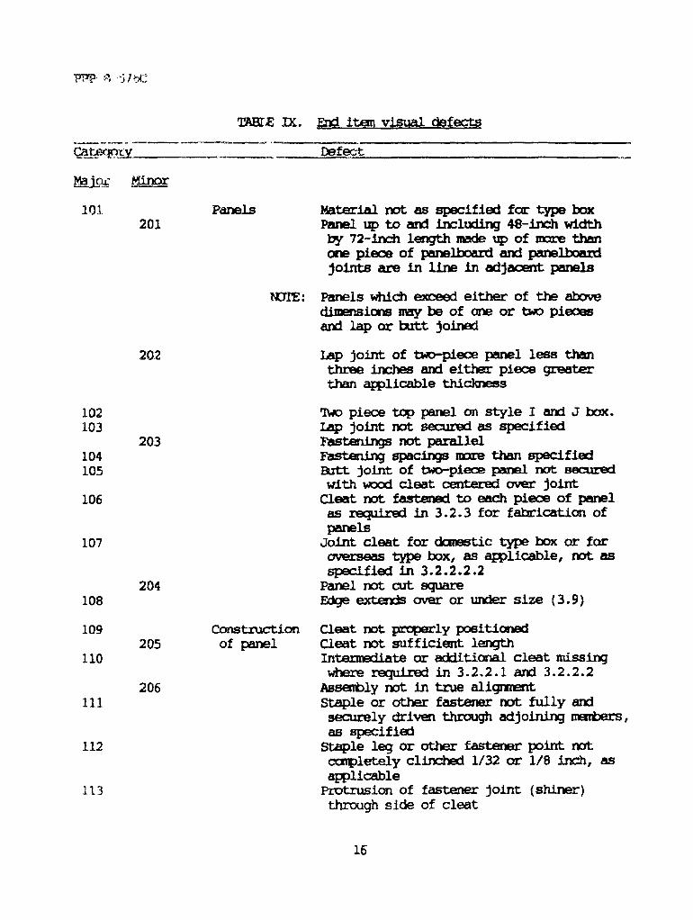
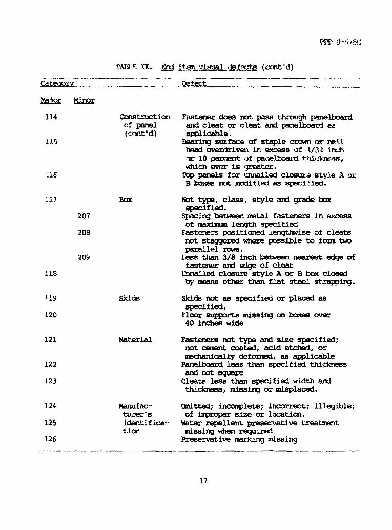
4.3.1 End item visual examination. The boxes shall be examined for thedefects listed in table IX. The lot size shall be expressed in units ofboxes of the same type, class, style, grade, (when applicable), and sizeoffered for inspection at one time. The sample unit shall be one box and itstop. The inspection level shall be S-4, and the acceptable quality level(AQL), expressed in terms of defects per hundred units, shall be 4.0 formajor defects and 10.0 for total (major and minor combined) defects.
15

FPP-8-576C
4.3.2 Packaging examination. The fully packaged end items snail beexamined for the defects listed below. The lot size shall be expressed inunits of shipping containers. She sample unit shall be one shippingcontainer fully packaged. The inspection level shall be S-2 and the AQLexpressed in terms of defects per hundred units, shall be 2.5.
Examine Defect
Marking (exterior Quitted; incorrect; illegible; of improper size,and interior) location, sequence, or method of application.
Materials Any component missing, damaged, or not asspecified.
Workmanship Inadequate application of components, such as:incomplete sealing or closure, Improper taping,loose strapping, or inadequate stapling. Bulged ordistorted container.
Content Number per container is more or less than required.
4.4 Methods of inspection.
4.4.1 Component tests for fasteners.
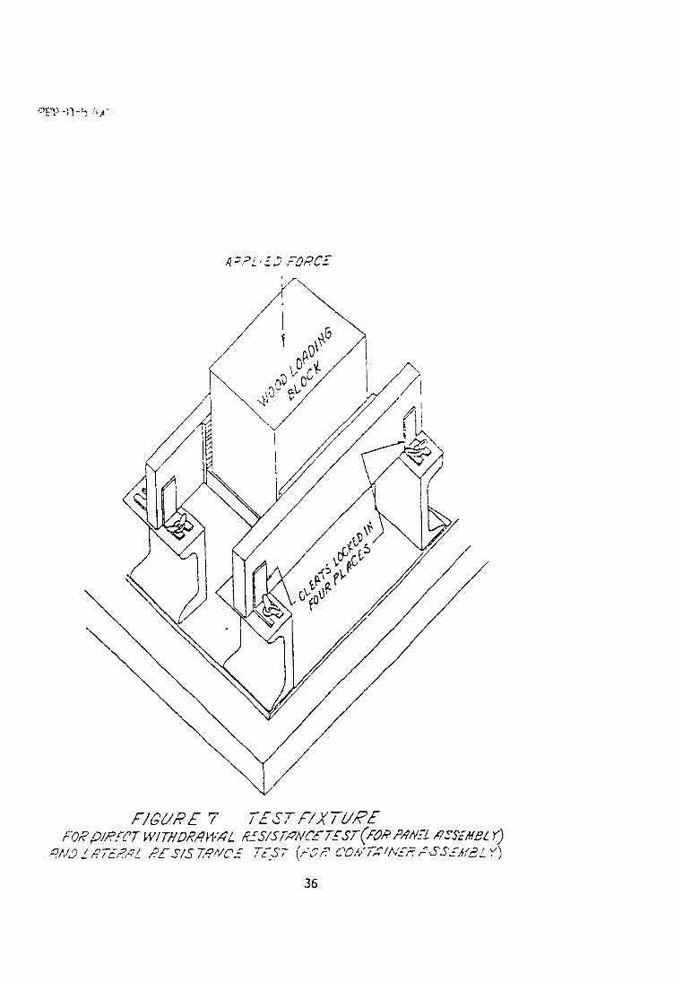
4.4.1.1 General. The tests in 4.4.1.2, and 4.4.1.3 are intended toindicate the relative performance of various types of fasteners when used inthe fabrication of wood cleated panel boxes. Since these tests arecomparative in nature, the appropriate cement coated nail designated in3.1.3.1 and of size specified for the purpose in table VII, VIII and DC mustbe tested concurrently with the alternate fasteners being considered toreplace it. Five test specimens are required for each variety of fastener tobe evaluated. Unless otherwise specified herein, these specimens shall beprepared from the same thickness and group of wood as will be employed infabricating the boxes and the width of the representative cleat sections ofthe test specimen shall be the same as that specified for the container inwhich the fasteners are planned to be used. No test specimen shall containsplit members. Nails and other fastenings shall be driven so that neitherthe head nor the point will project above the surface of the wood (except forthe purpose of clinching where required). Specimens shall be cut andfabricated so that only side-grain nailing results. Each of the tests shallbe performed on a compression tester equipped with an autographic recorderfor producing force-deflection curves. 1toe test fixtures for holding thetest specimen, as illustrated in figures 7 and 10, shall be designed so thatthe applied force is perpendicular to the plane of the test member in contactwith the loading block. Also, the test fixtures and loading blocks shall bedimensioned bo provide clearances sufficient to prevent direct contact of thetest specimen with the platens of the compression tester at any time during
18

PPP-B-576C
test prior to failure. The platen speed shall be 0.4 inch per minute + 0.1inch per minute, failure is denoted by the complete separation of one memberfrom another in the specimen and shall be recorded in terms of the energyrequired to produce this separation. The required "energy-to-failure" valuefor each test specimen shall be determined by measuring the area under theforce-deflection curve from the point of initial loading to the failurepoint. The average "energy-to-failure" values obtained with the nails andwith the other fasteners shall be calculated and this data used to determinethe total number of fasteners required. The total number of fasteners shallbe not less than the total number of nails that would be required. Whenadditional fasteners are required, the increase should be limited to thenumber which can be used without causing splitting of the wood members of thebox during assembly,
4.4.1.2 Test of fasteners for securing cleats to panelboard panels. Thetest specimen shall consist of two sections of representative cleat stockmeasuring 14 inches in length, each secured with a test fastener as shown infigure 6, to the opposite edges of a representative container panel boardpanel section measuring 6 by 12 inches. The two fasteners used to assemblethe specimen shall be located as shown in figure 6 and shall be clinched notless than 1/8 inch. The test specimens shall be mounted in a test fixturesuch as illustrated in figure 7. The test fixture rests on the lower platenof the compression tester and the compression load is applied to the woodloading block which transmits the applied force to the specimen memberrepresenting the container end section. The loading block dimensions shallbe such that the block covers the entire area of the specimen member it is incontact with except for a 1/4-inch clearance between the sides of the blockand the adjacent cleat members. Testing of the specimen shall be performedas described in 4.4.1.1.
4.4.1.2.1 (Type III boxes) water resistance of glued joints (for class 1domestic)(see 3.2.1). If the fiberboard is fastened to the cleats by glueonly, the water resistance of the glue shall be determined by loss ofadhesion when exposed to water. Samples of the panels shall be madewatertight at the corners only where the cleats join, by applying a suitablematerial such as molten wax of paraffin. The panel, cleats up, shall befilled with water at room temperature to 1/16 inch of the upper surfaces ofthe cleats. This water level shall be maintained for not less than 24 hours.Each cleat in succession shall be torn from the fiberboard by hand, usingthe fingers. The portion of fiberboard remaining in contact with the cleatshall cover not less than 75 percent of the area of the cleat.
4.4.1.3 Test of fasteners for container assembly.
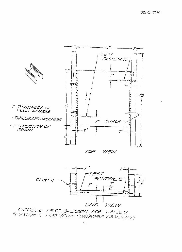
4.4.1.3.1 lateral resistance test. The test specimen shall consist of twosections of representative cleat stock, measuring 2-1/4 by 10 inches, eachsecured with one test fastener as shown in figure 8 to the opposite edges ofa representative container panel section measuring 6 by 6 inches. The total
19

PPP-B-576C
of two test fasteners used to assemble the specimen shall be located as shownin figure 8. The specimen test fixture and the testing procedure shall be asdescribed in 4.4.1.1.
4.4.1.3.2 Direct withdrawal resistance test. The test specimen shallconsist of a section of representative cleat stock, measuring 3 by 10 inches,secured with three test fasteners as shown in figure 9, to a representativecontainer panel section measuring 5 by 6 inches. The fasteners used toassemble the specimen shall be located as shown in figure 9. The testspecimens shall be mounted in a test fixture such as illustrated in figure10. The test fixture rests an the lower platen of the compression tester andthe compression load is applied to the wood loading block which transmits theapplied force to the member representing the container panel section. Theloading block dimensions are such that the block covers the entire area ofthe specimen member it is in contact with except for a 1/4-inch clearancebetween the side walls of the slot in the wood loading block and the adjacentparallel surfaces of the test specimen. The depth of the slot should begreat enough to prevent contact of the loading block with the portion of thetest specimen within the slot at any time during testing. Testing of thespecimen shall be performed as described in 4.4.1.1.
4.4.2 End item testing. The completely assembled boxes shall be testedfor preservative treatment. The lot size shall be expressed in terms ofcompletely assembled boxes. The sample size shall be one completelyassembled box. The inspection level shall be S-4. The assembled box shallbe placed on either end with top open. Any failure to meet the colorrequirements specified in 4.4.2.1 and 4.4.2.2 shall be cause for rejection ofthe lot.
4.4.2.1 PQ 56 (c«oper-8-quinolinolate) preservative test. Two drops of aformulation containing 10 parts, by weight, of sodium diethyl-dithiocarbamatetrihydrate (see 6.4.3) and 90 parts, by weight, of distilled water shall beapplied to the wood surface. An immediate dark brown coloration and thespreading of drops shall indicate the presence of PQ 56 treatment. Analternate method is to spray, over the dried wood surface, a solution ofdissolved 0.5 grains chrome azurol S concentrate (see 6.4.4) and 5.0 grams ofsodium acetate in 80 mL of distilled water, and diluted further to 500 mLtotal distilled water. A deep blue color reveals the presence of copper(from copper-8-guinolinolate).
4.4.2.2 M-GARD W 550 (zinc napthenate emulsifiable) preservative test.Prepare daily a solution of 0.1 gram of dissolved dithizone(diphenylthiocarbazone) (see 6.4.5) in 100 mL of chloroform and spray evenlyover dried wood. A pink color indicates the presence of zinc. (NOTE: Thepink color fades with light.) An alternate method is to prepare a mixture of10 mL each of three stock solutions and pour them into an atomizer (sprayer).The first stock solution is comprised of 1 gram of potassium ferricyanidedissolved in 100 mL of distilled water. The second solution is made of
20

PPP-B-576C:
1gram of soluble starch in about 5 mLof distilled water which is added to100 mL of distilled water and boiled for one minute with constant stirring, andthen cooled. (NOTE: This solution is subject to biodegradation and shouldnot be used longer than three days.) Spray the mixture evenly over the driedwood surface. The solution will cause the treated wood to turn a deep blueimmediately/ and the untreated part will retain its original color.
5. PPEPARATION FOR DELIVERY
5.1 Packing. Packing shall be level C, or commercial as specified (see6.2).
5.1.1 Level C. Boxers are to be shipped completely assembled (except fortops) or knocked down as specified (see 6.2). The tops for boxes shippedcompletely assembled, and panels of like sizes for boxes shipped knocked downshall be bundled boxed or crated in quantities that permit easy loading andhandling. Boxes shall be packed in a manner to ensure carrier acceptance andsafe delivery at destination at the lowest transportation rate for suchsupplies.
5.1.2 Commercial packing. Boxes shall be packed in accordance withASTM D 3951.
5.2 Marking. In addition to any special marking required by the contract,shipments shall be marked in accordance with FED-STD-123, ASTM D 3951 orMIL-STD-129, as applicable.
6. NOTES
(This section contains information of a general or explanatory nature thatmay be helpful, but is not mandatory.)
6.1 Intended use. Boxes covered by this specification are intended to beused for domestic and overseas shipment of general materials and supplies.Styles A and B are fully cleated and are stronger than styles I and J. StyleA lends itself to ease in assembly and opening. Style B, with its 3-waycorner construction, has greater strength than style A but is more difficultto assemble and open. Styles I and J provide greater water shedding abilitythan style A or B. The unnailed closure option for style A or B is intendedfor use where shiners may damage contents or when reuse of the box is animportant consideration. Types I and III boxes are normally used by allMilitary services and type II boxes are presently used by the Air Force.
6.1.1 Class 1 domestic boxes. Class 1 domestic boxes are for domesticshipments and for off-shore and overseas shipments contemplating protectedstorage and commercial type handling.
21
PPP-B-576C
6.1.2 Class 2 overseas boxes. Class 2 overseas boxes are for overseasshipments and handling in military supply systems, subject to repeatedrehandling and unprotected storage, and which may also be subject toextreme climatic hazards and temperature and humidity conditions such ashave been experienced in combat operations in tropical rain forests (e.g.,Southeast Asia).
6.1.3 Shipments of subsistence and clothing. Shipments of subsistence orclothing shall not be made in boxes fabricated from toxic-treated wood orpanel board.
6.1.4 Shipments of exceptional commodities. For shipments of exceptionalcommodities, contracting agencies may require better boxes than thosespecified herein. Where the nature of the contents are classified asexplosive or dangerous, the container must conform to the specificationsprescribed in the Department of Transportation Regulations GoverningTransportation of Explosive and other Dangerous Articles. (The InterstateCommerce Commission Regulations apply to such articles as explosives,flammable and corrosive liquids, compressed gases, flammable solids,oxidizing materials, poisons, etc.)
6.2 Acquisition requirements. Acquisition documents should specify thefollowing:
a. Title, number, and date of this specification.b. Type class style and treatment of box required (see 1.2.1, 1.2.2
and 1.2.3).c. When style 1A top panel closure is unnailed (see 1.2.3).d. Weight of contents (see tables I, II, III, IV, V, and VI).e. Quality classification of cleat lumber required (see 3.1.2).f. Lumber used for fabrication of skids (see 3.1.2).g. Intermediate cleat requirements for class 1 domestic, and
class 2 overseas styles I and J (see 3.2.2.1).h. When skids are not required for boxes with gross weights of 200
pounds or 100 pounds with dimensions of 48 by 24 inches or more(see 3.4).
i. When beveling of skids is required (see 3.4).j. When four-way entry skids are required and when 3-1/2 by 4 inch
built up skids are required (see 3.4).k. When container manufacturer's identification is not required
(see 3.5).1. Dimensions of box (see 3.3.2).m. When preservation is required (see 1.2.4, 3.7 and 6.5).n. Applicable level of packing (see 5.1).o. Whether boxes are to be shipped assembled or knocked-down
(see 5.1.1).p. When class 1 domestic boxes require strapping (see 10.1).
22

PPP-B-376C
q. When SEAL joint specimens ARE Required prior to strappingoperations (see 40.1.2.2).
r. When class 3 or 4 fire retardant boxes are required (see 1,2.2and 3.8).
6.3 Type of load (see 3.2.2 and tables I and IX). The construction of aclass 2 overseas cleated panelboard box is determined by the weight ofcontents and type of load. Load types are defined as type I, easy load; typeII, average load; and type III, difficult load; as described under "Loadtype" in ASTM D 996.
6.4 Solution information,
6.4.1 PQ 56 (copper--8-quinolinate), Product may be obtained from ISKBiotech, Industrial Biosides Division, 6075 Poplar Avenue, Suite 306,Memphis, IN 38119 or equivalent manufacturer.
6.4.2 M-GARD W 550 (zinc napthenate emulsifiable). Product may beobtained from CMS, Inc., 2301 Scranton Road, Cleveland, CH 44113 orequivalent manufacturer.
6.4.3 Sodium diethyldithiocarbamate trihvdrate. Product may be obtainedfrom J.T. Baker, Inc., 222 Red School Lane, Phillipsburg, NJ 08865 orequivalent manufacturer.
6.4.4 Chrome azurol S. Product may be obtained from Eastman FineChemical, Laboratory & Research Products, Building 701, Rochester, NY14652-3512 or equivalent manufacturer.
6.4.5 Dithizone (diphenlythiocarbazone). Product may be obtainedfrom Mallinckrodt, Inc./Mallinckrodt Specialty ChemicalB Co., ScienceProducts Division, 675 Mc Donnell Blvd., P.O. Box 5840, St. Louis, MO63134 or equivalent manufacturer.
6.5 Fire retardant boxes (class 3 and class 4) . Fire retardant boxes areintended to reduce the risks and hazards of fire aboard ships and warehousesand to improve readiness by reducing losses due to fire destruction incompliance with the Navy Passive Fire Protection Program and other servicesprograms.
6.6 Illustration information. Figures 1 through 10 are not drawings andshould be treated as informational illustrations.
6.7 Subject term (key word) listing.
BoxWoodCleated
23
PPP-B-576C
PanelShipping containerNailsStaples
6.8 Changes from previous issue. Asterisks (or vertical lines) are notused in this revision to identify changes with respect to the previous issuedue to the extensiveness of the changes.
MILITARY INTERESTS: CIVIL AGENCY COORDINATING ACTIVITIES:
Custodians GSA - FSS
Army - GLNavy - SA PREPARING ACTIVITY:Air Force - 69
Army - GLReview Activities
Project 8115-0532Army - AV, EA, SM Air Force - 99
User Activities
Army - ARNavy - MS, AS, SH
24
BOXES, WOOD-CLEATED PANELBOARD
10. SCOPE
10.1 Scope. This appendix covers requirements for steel strapping andinspection for the application of strapping to boxes, wood-cleatedpanelboard. When specified (see 6.2), class 1 domestic boxes shall bestrapped In conformance with this appendix. Unless otherwise specified (see6.2), class 2 overseas boxes shall be strapped in conformance with thisappendix specification and the references cited herein, the text of thisspecification shall take precedence, Nothing Ln this specification, however,shall supersede applicable laws and regulations unless a specific exemptionhas been obtained,
20. APPLICABU: DOCUMENTS
20.1 The following specification, of the issues in effect on date ofinvitation for bids or request for proposal, form a part of this appendix tothe extent specified herein.
Federal Standard:
FED-SID-101 - Test Procedures for Packaging Materials
Other Publications
American Society for Testing and Materials
D 3953 - Specification for Strapping, Flat Steel and Seals
30. REQUIREMENTS
30.1 General. Strapping required herein shall be performed when the boxis packed for shipment. Strapping materials shall be furnished by the boxpacker, and shall be either round wire strapping as specified in tables XI,XII and XIII or flat metal strapping conforming to class 1, type I, III orIV, finish A or B of ASTM D 3953. The round wire shall be galvanized.
30.2 Size of strapping. The diameter of round-wire strapping shall be asgiven in table XI and size of flat strapping shall be as given in tables XIIor XIII as applicable.
25


30.3 Tensile strenqth. The strength of the seal joint shall be not less than75 percent of the tensile strength of the flat or round wire, strapping, asapplicable, when tested as specified in 40.2.
30.4 Tightness. The straps shall be drawn tight so as to sink into thewood at the edges. Unless otherwise specified herein, straps or wiresshall be stapled to the cleats at a distance not to exceed 4 inches fromthe edge or face of the box with cement-coated or chemically etchedstaples, spaced at intervals of approximately 6 inches. Strapping on thebottom of the box shall not be stapled. Strapping applied over filleredge cleats of the top panel of the box shall not be stapled. One stapleshall be applied over each strap into the through edge cleats on the toppanel of the box. Staples shall be not less than 0.080 inch in diameter(No. 14 gage), in accordance with FF-N-105 or the equivalent cross -section area, unless machine driven, in which case the staple shall benot less than 0.0475 inch in diameter (No. 18 gage). The length ofstaple shall be approximately 3/4 inch. When driven over flat strap,the staple shall be approximately 1/8 inch wider than the flat metalbands. Staples shall be driven so as not to damage the strapping. Staplesshall be applied just prior to shipment where practicable.
30.3 Location and number of straps. All straps shall be appliedperpendicular to the edge of the box and be positioned only over the cleatsof the applicable style of box. Two straps shall be applied lengthwise tothe box on the edge cleats over the ends, top and bottom for styles A and B.Two straps shall be applied lengthwise (horizontally) to the box on the edgecleats over the ends and sides for styles I and J. When intermediate cleatsare required on the sides, top, or bottom a girth-wise strap shall be locatedover each intermediate cleat and shall be positioned on top of the longitud-inal straps. When an intermediate cleat is required on an end panel,strapping shall not be required over this intermediate end cleat. Inapplying straps, care must be exercised so that straps do not pass over voidsbetween cleats and thus become susceptible to snagging. Alternatively, eachlengthwise and girthwise strap may be replaced by three corner flat strapseach 8 inches long and secured to the container by three staples on each legpneumatically driven through the strap into the cleats. The flat strappingshall be the same width, thickness, type, finish and grade as specified in30.1 and table XII. Alternatively, the strapping may be the nail on type.Corner straps (nail on) shall not be used on unnailed closure boxes (such asstyle Al).
40. INSPECTION
40.1 Box inspection. Boxes shall be inspected to determine compliancewith closure and strapping requirements of this appendix. Sampling shall beperformed in accordance with MIL-STD-105.
27

PPP-B-576C
40.1.1 Inspection for closure and strapping. Classification of defectsshall be as specified in table XIV. The lot size shall be expressed in unitsof boxes, The sample unit shall be one complete box. The inspection levelshall be S-3 and the AQL, expressed in terms of defects per hundred units,shall be 4.0.
TABLE XIII. Examination for closure and strapping
Category Examine Defect
Major101 Strapping (flat Not size specified (see tables XI, XII
or round, as and XIII102 applicable) Not applied as specified103 Missing strap104 Loose strap105 Torn or cut strap
106 Staples More than 4 inches from edge of box
107 Less than size specified108 Not spaced as specified
40.1.2 Testing of seal joint
40.1.2.1 Unless otherwise specified in 40.1.2.2, three separate jointspecimens shall be taken from sample containers of each lot of strapped boxessubmitted for inspection in 40.1.1 and tested aaspecified in 40.2. If theseal strength of one or more of the three specimens are less than therequirements of 30.3 it shall be cause for rejection of the lot.
40.1.2.2 When specified (see 6.2), three separate joint specimens shall bemade prior to the commencement of the strapping of containers and each time adifferent reel of strapping, strapping tools or kinds of seals are used andsubmitted for test as specified in 40.2. If the seal joint strength of oneor more of the three specimens is less than the requirements of 30.3 it shallbe cause for rejection of the lot.
40.2 Tensile strength test of seal joint. The seal joint shall be testedin accordance with Method 2044 of FED-STD-101.
28

Figure 1— Styles of cleated panel board boxes
29
Stule F
Stule I

TOP PANEL MODIFICATON OF UNNAILED CLOSURE,STYLE Al, BOX FIGURE l-A
30