I-Line™ Combo Panelboard - Schneider · PDF fileI-Line™ Combo Panelboard...
20
™ I-Line™ Combo Panelboard Distribution Panelboards Catalog 2110CT1301 2013 Class 2110 Contents Description Page Product Description . . . . . . . . . . . . . . . . . . . . . . . . . . . . . . . 2 Standards . . . . . . . . . . . . . . . . . . . . . . . . . . . . . . . . . . . . . 2 Service . . . . . . . . . . . . . . . . . . . . . . . . . . . . . . . . . . . . . . . 3 Enclosure Protection . . . . . . . . . . . . . . . . . . . . . . . . . . . . 4 Main Circuit Breaker Panelboards . . . . . . . . . . . . . . . . . . 5 Main Lugs-only Panelboards . . . . . . . . . . . . . . . . . . . . . . 5 Solid Neutral. . . . . . . . . . . . . . . . . . . . . . . . . . . . . . . . . . . 5 Branch Circuit Breakers . . . . . . . . . . . . . . . . . . . . . . . . . . 5 Description Page Features and Benefits. . . . . . . . . . . . . . . . . . . . . . . . . . . . . 6 Accessories and Kits . . . . . . . . . . . . . . . . . . . . . . . . . . . . . 8 Available Ready-to-Install Kits. . . . . . . . . . . . . . . . . . . . . 8 Available Factory Installed Options . . . . . . . . . . . . . . . . . 8 Accessories . . . . . . . . . . . . . . . . . . . . . . . . . . . . . . . . . . . 9 General and Application Information . . . . . . . . . . . . . . . . 10 Enclosure Dimensions . . . . . . . . . . . . . . . . . . . . . . . . . . . . 11 Replacement Parts . . . . . . . . . . . . . . . . . . . . . . . . . . . . . . 19
Transcript of I-Line™ Combo Panelboard - Schneider · PDF fileI-Line™ Combo Panelboard...
™
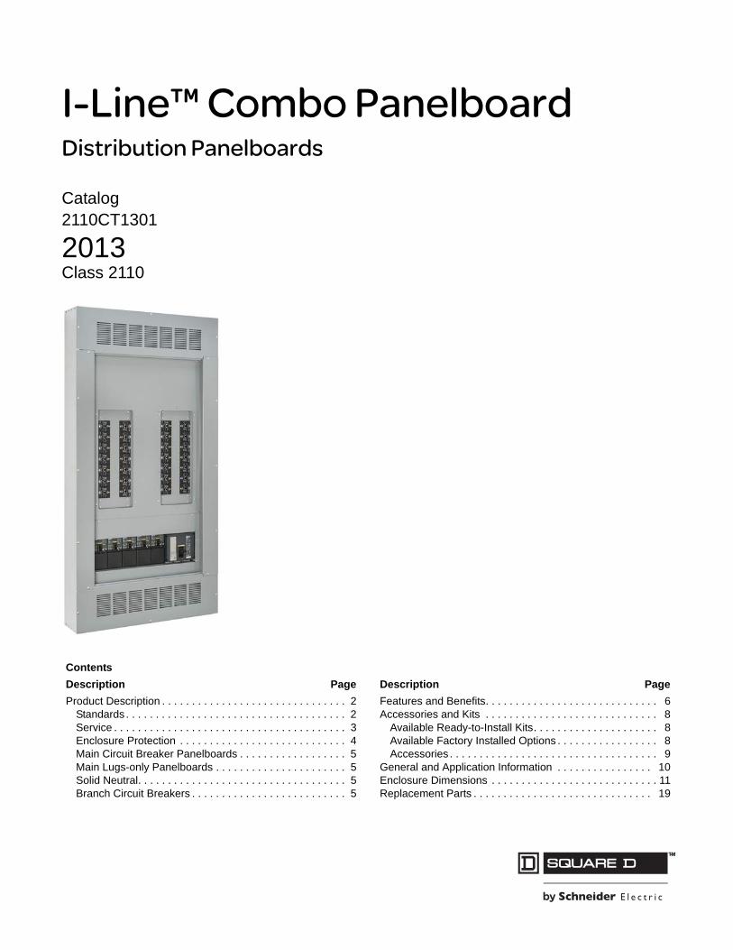
I-Line™ Combo PanelboardDistribution Panelboards
Catalog2110CT1301
2013Class 2110
Contents
Description Page
Product Description . . . . . . . . . . . . . . . . . . . . . . . . . . . . . . . 2Standards . . . . . . . . . . . . . . . . . . . . . . . . . . . . . . . . . . . . . 2Service . . . . . . . . . . . . . . . . . . . . . . . . . . . . . . . . . . . . . . . 3Enclosure Protection . . . . . . . . . . . . . . . . . . . . . . . . . . . . 4Main Circuit Breaker Panelboards . . . . . . . . . . . . . . . . . . 5Main Lugs-only Panelboards . . . . . . . . . . . . . . . . . . . . . . 5Solid Neutral. . . . . . . . . . . . . . . . . . . . . . . . . . . . . . . . . . . 5Branch Circuit Breakers . . . . . . . . . . . . . . . . . . . . . . . . . . 5
Description Page
Features and Benefits. . . . . . . . . . . . . . . . . . . . . . . . . . . . . 6Accessories and Kits . . . . . . . . . . . . . . . . . . . . . . . . . . . . . 8
Available Ready-to-Install Kits. . . . . . . . . . . . . . . . . . . . . 8Available Factory Installed Options . . . . . . . . . . . . . . . . . 8Accessories . . . . . . . . . . . . . . . . . . . . . . . . . . . . . . . . . . . 9
General and Application Information . . . . . . . . . . . . . . . . 10Enclosure Dimensions . . . . . . . . . . . . . . . . . . . . . . . . . . . . 11Replacement Parts . . . . . . . . . . . . . . . . . . . . . . . . . . . . . . 19
I-Line™ Combo PanelboardProduct Description
208/2013 ™ © 2013 Schneider Electric
All Rights Reserved
Product Description
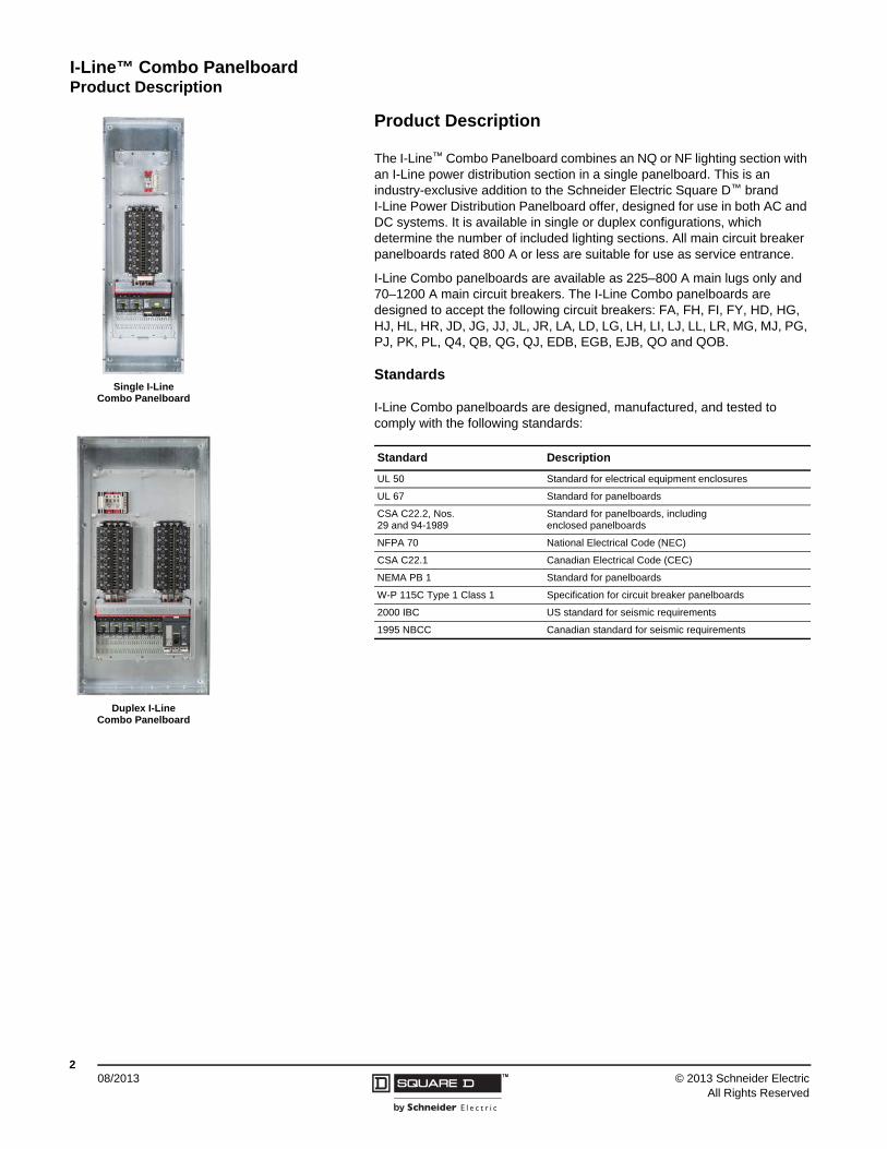
The I-Line™ Combo Panelboard combines an NQ or NF lighting section with an I-Line power distribution section in a single panelboard. This is an industry-exclusive addition to the Schneider Electric Square D™ brand I-Line Power Distribution Panelboard offer, designed for use in both AC and DC systems. It is available in single or duplex configurations, which determine the number of included lighting sections. All main circuit breaker panelboards rated 800 A or less are suitable for use as service entrance.
I-Line Combo panelboards are available as 225–800 A main lugs only and 70–1200 A main circuit breakers. The I-Line Combo panelboards are designed to accept the following circuit breakers: FA, FH, FI, FY, HD, HG, HJ, HL, HR, JD, JG, JJ, JL, JR, LA, LD, LG, LH, LI, LJ, LL, LR, MG, MJ, PG, PJ, PK, PL, Q4, QB, QG, QJ, EDB, EGB, EJB, QO and QOB.
Standards
I-Line Combo panelboards are designed, manufactured, and tested to comply with the following standards:
Standard Description
UL 50 Standard for electrical equipment enclosures
UL 67 Standard for panelboards
CSA C22.2, Nos. 29 and 94-1989
Standard for panelboards, including enclosed panelboards
NFPA 70 National Electrical Code (NEC)
CSA C22.1 Canadian Electrical Code (CEC)
NEMA PB 1 Standard for panelboards
W-P 115C Type 1 Class 1 Specification for circuit breaker panelboards
2000 IBC US standard for seismic requirements
1995 NBCC Canadian standard for seismic requirements
Single I-Line Combo Panelboard
Duplex I-Line Combo Panelboard
I-Line™ Combo PanelboardProduct Description
308/2013™© 2013 Schneider Electric
All Rights Reserved
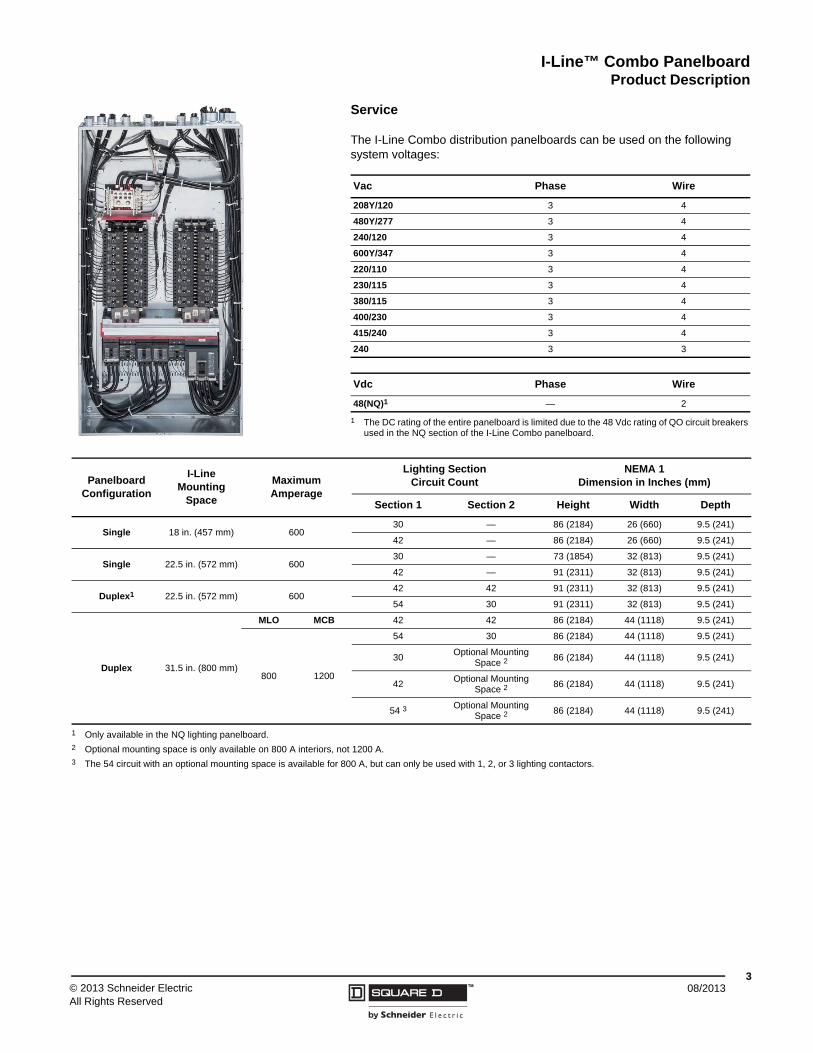
Service
The I-Line Combo distribution panelboards can be used on the following system voltages:
Vac Phase Wire
208Y/120 3 4
480Y/277 3 4
240/120 3 4
600Y/347 3 4
220/110 3 4
230/115 3 4
380/115 3 4
400/230 3 4
415/240 3 4
240 3 3
Vdc Phase Wire
48(NQ)1
1 The DC rating of the entire panelboard is limited due to the 48 Vdc rating of QO circuit breakers used in the NQ section of the I-Line Combo panelboard.
— 2
Panelboard Configuration
I-Line Mounting
Space
Maximum Amperage
Lighting Section Circuit Count
NEMA 1 Dimension in Inches (mm)
Section 1 Section 2 Height Width Depth
Single 18 in. (457 mm) 60030 — 86 (2184) 26 (660) 9.5 (241)
42 — 86 (2184) 26 (660) 9.5 (241)
Single 22.5 in. (572 mm) 60030 — 73 (1854) 32 (813) 9.5 (241)
42 — 91 (2311) 32 (813) 9.5 (241)
Duplex1 22.5 in. (572 mm) 60042 42 91 (2311) 32 (813) 9.5 (241)
54 30 91 (2311) 32 (813) 9.5 (241)
Duplex 31.5 in. (800 mm)
MLO MCB 42 42 86 (2184) 44 (1118) 9.5 (241)
800 1200
54 30 86 (2184) 44 (1118) 9.5 (241)
30Optional Mounting
Space 286 (2184) 44 (1118) 9.5 (241)
42Optional Mounting
Space 286 (2184) 44 (1118) 9.5 (241)
54 3Optional Mounting
Space 286 (2184) 44 (1118) 9.5 (241)
1 Only available in the NQ lighting panelboard.2 Optional mounting space is only available on 800 A interiors, not 1200 A.3 The 54 circuit with an optional mounting space is available for 800 A, but can only be used with 1, 2, or 3 lighting contactors.
I-Line™ Combo Panelboard Product Description
408/2013 ™ © 2013 Schneider Electric
All Rights Reserved
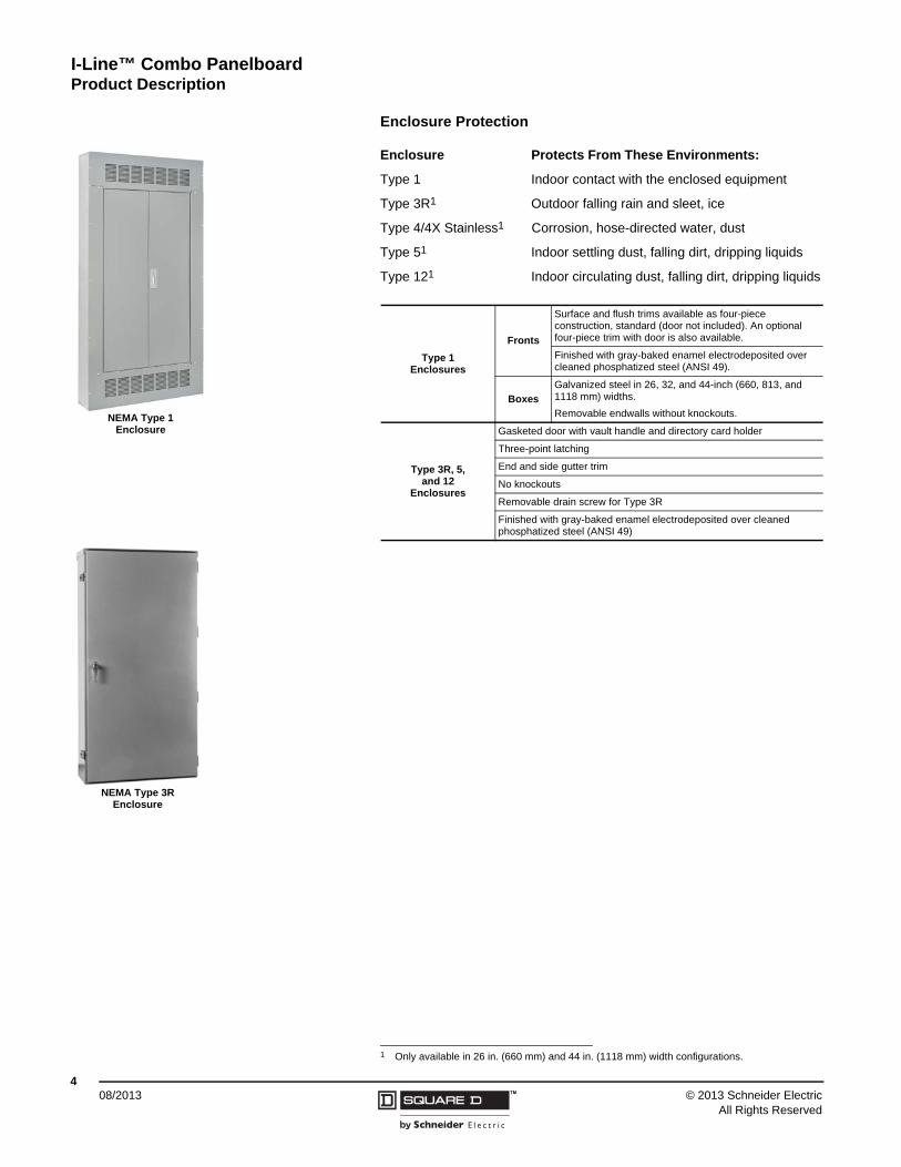
Enclosure Protection
Enclosure Protects From These Environments:
Type 1 Indoor contact with the enclosed equipment
Type 3R1 Outdoor falling rain and sleet, ice
Type 4/4X Stainless1 Corrosion, hose-directed water, dust
Type 51 Indoor settling dust, falling dirt, dripping liquids
Type 121 Indoor circulating dust, falling dirt, dripping liquids
1 Only available in 26 in. (660 mm) and 44 in. (1118 mm) width configurations.
Type 1 Enclosures
Fronts
Surface and flush trims available as four-piece construction, standard (door not included). An optional four-piece trim with door is also available.
Finished with gray-baked enamel electrodeposited over cleaned phosphatized steel (ANSI 49).
Boxes
Galvanized steel in 26, 32, and 44-inch (660, 813, and 1118 mm) widths.
Removable endwalls without knockouts.
Type 3R, 5,and 12
Enclosures
Gasketed door with vault handle and directory card holder
Three-point latching
End and side gutter trim
No knockouts
Removable drain screw for Type 3R
Finished with gray-baked enamel electrodeposited over cleaned phosphatized steel (ANSI 49)
NEMA Type 1 Enclosure
NEMA Type 3R Enclosure
I-Line™ Combo PanelboardProduct Description
508/2013™© 2013 Schneider Electric
All Rights Reserved
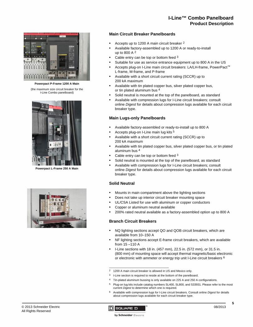
Main Circuit Breaker Panelboards
• Accepts up to 1200 A main circuit breaker 2
• Available factory-assembled up to 1200 A or ready-to-install up to 800 A 2
• Cable entry can be top or bottom feed 3
• Suitable for use as service entrance equipment up to 800 A in the US• Accepts plug-on I-Line main circuit breakers: LA/LH-frame, PowerPact™
L-frame, M-frame, and P-frame• Available with a short circuit current rating (SCCR) up to
200 kA maximum• Available with tin plated copper bus, silver plated copper bus,
or tin plated aluminum bus 4
• Solid neutral is mounted at the top of the panelboard, as standard• Available with compression lugs for I-Line circuit breakers; consult
online Digest for details about compression lugs available for each circuit breaker type.
Main Lugs-only Panelboards
• Available factory-assembled or ready-to-install up to 800 A• Accepts plug-on I-Line main lug kits 5
• Available with a short circuit current rating (SCCR) up to 200 kA maximum
• Available with tin plated copper bus, silver plated copper bus, or tin plated aluminum bus 4
• Cable entry can be top or bottom feed 3
• Solid neutral is mounted at the top of the panelboard, as standard• Available with compression lugs for I-Line circuit breakers; consult
online Digest for details about compression lugs available for each circuit breaker type.
Solid Neutral
• Mounts in main compartment above the lighting sections• Does not take up interior circuit breaker mounting space• UL/CSA Listed for use with aluminum or copper conductors• Copper or aluminum neutral available• 200% rated neutral available as a factory-assembled option up to 800 A
Branch Circuit Breakers
• NQ lighting sections accept QO and QOB circuit breakers, which are available from 10–150 A
• NF lighting sections accept E-frame circuit breakers, which are available from 15 –110 A
• I-Line sections with 18 in. (457 mm), 22.5 in. (572 mm), or 31.5 in. (800 mm) of mounting space will accept thermal magnetic/basic electronic or electronic with ammeter or energy trip unit I-Line circuit breakers 6
2 1200 A main circuit breaker is allowed in US and Mexico only.3 I-Line section is required to reside at the bottom of the panelboard.4 Tin-plated aluminum bussing is only available on 225 A and 250 A configurations.5 Plug-on lug kits include catalog numbers SL400, SL800, and S33931. Please refer to the most
current Digest to determine which one is required.6 Available with compression lugs for I-Line circuit breakers. Consult online Digest for details
about compression lugs available for each circuit breaker type.
Powerpact P-Frame 1200 A Main
(the maximum size circuit breaker for the I-Line Combo panelboard)
Powerpact L-Frame 250 A Main
I-Line™ Combo Panelboard Features and Benefits
608/2013 ™ © 2013 Schneider Electric
All Rights Reserved
Features and Benefits
Listed below are some of the benefits of the I-Line Combo panelboard.
Ease of Installation
The I-Line Combo panelboard provides a simple, quick installation due to the minimal amount of materials needed and the benefit of only having to install a single panelboard.
Reduced Footprint
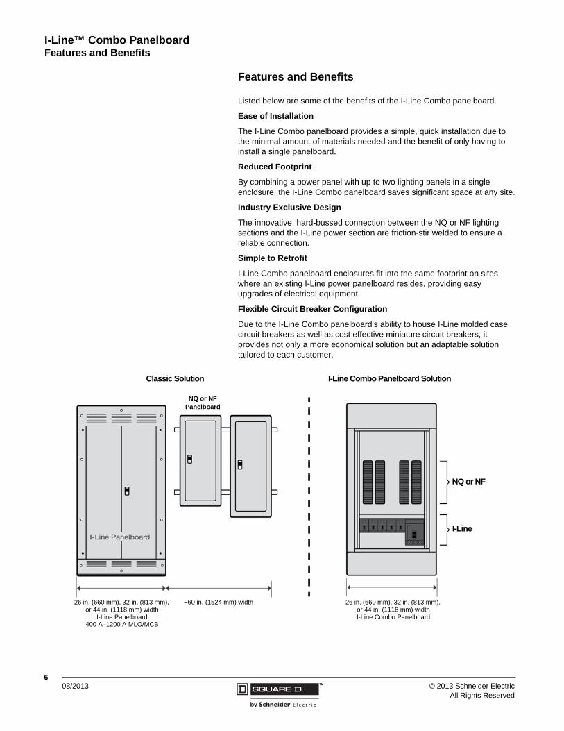
By combining a power panel with up to two lighting panels in a single enclosure, the I-Line Combo panelboard saves significant space at any site.
Industry Exclusive Design
The innovative, hard-bussed connection between the NQ or NF lighting sections and the I-Line power section are friction-stir welded to ensure a reliable connection.
Simple to Retrofit
I-Line Combo panelboard enclosures fit into the same footprint on sites where an existing I-Line power panelboard resides, providing easy upgrades of electrical equipment.
Flexible Circuit Breaker Configuration
Due to the I-Line Combo panelboard's ability to house I-Line molded case circuit breakers as well as cost effective miniature circuit breakers, it provides not only a more economical solution but an adaptable solution tailored to each customer.
NQ or NF
I-Line
Classic Solution
26 in. (660 mm), 32 in. (813 mm), or 44 in. (1118 mm) width
I-Line Panelboard400 A–1200 A MLO/MCB
~60 in. (1524 mm) width
NQ or NFPanelboard
I-Line Combo Panelboard Solution
26 in. (660 mm), 32 in. (813 mm), or 44 in. (1118 mm) widthI-Line Combo Panelboard
I-Line™ Combo PanelboardFeatures and Benefits
708/2013™© 2013 Schneider Electric
All Rights Reserved
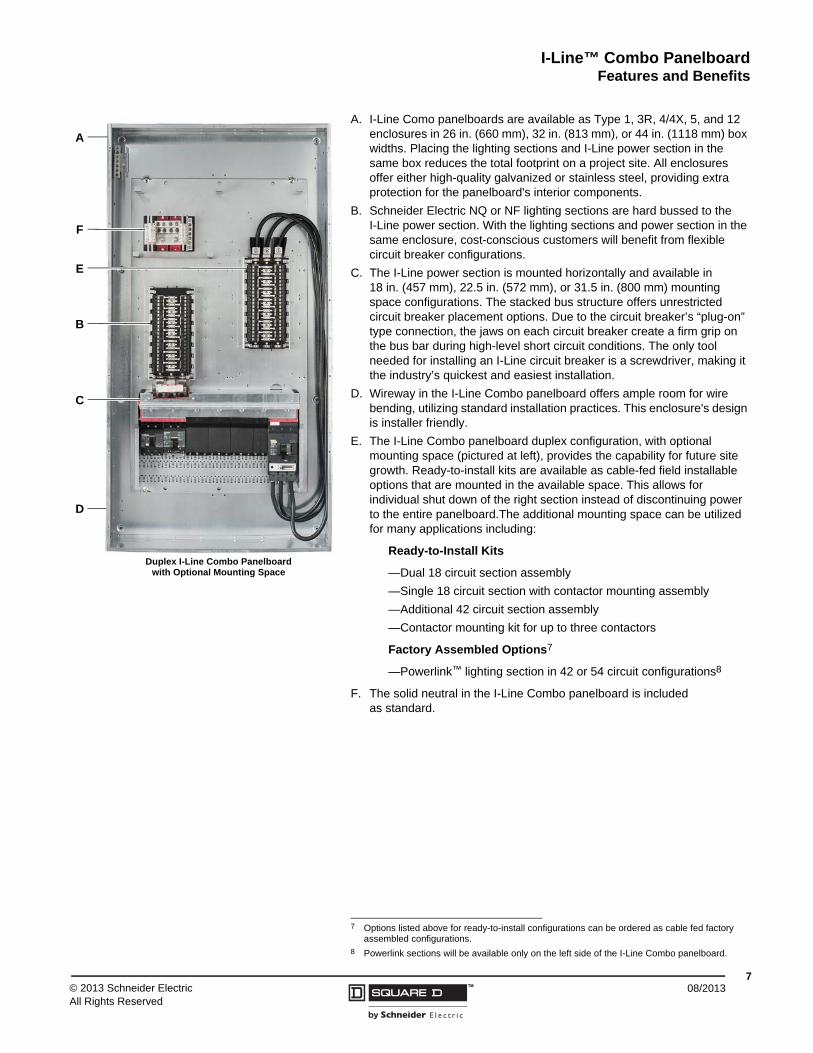
A. I-Line Como panelboards are available as Type 1, 3R, 4/4X, 5, and 12 enclosures in 26 in. (660 mm), 32 in. (813 mm), or 44 in. (1118 mm) box widths. Placing the lighting sections and I-Line power section in the same box reduces the total footprint on a project site. All enclosures offer either high-quality galvanized or stainless steel, providing extra protection for the panelboard's interior components.
B. Schneider Electric NQ or NF lighting sections are hard bussed to the I-Line power section. With the lighting sections and power section in the same enclosure, cost-conscious customers will benefit from flexible circuit breaker configurations.
C. The I-Line power section is mounted horizontally and available in 18 in. (457 mm), 22.5 in. (572 mm), or 31.5 in. (800 mm) mounting space configurations. The stacked bus structure offers unrestricted circuit breaker placement options. Due to the circuit breaker’s “plug-on” type connection, the jaws on each circuit breaker create a firm grip on the bus bar during high-level short circuit conditions. The only tool needed for installing an I-Line circuit breaker is a screwdriver, making it the industry’s quickest and easiest installation.
D. Wireway in the I-Line Combo panelboard offers ample room for wire bending, utilizing standard installation practices. This enclosure's design is installer friendly.
E. The I-Line Combo panelboard duplex configuration, with optional mounting space (pictured at left), provides the capability for future site growth. Ready-to-install kits are available as cable-fed field installable options that are mounted in the available space. This allows for individual shut down of the right section instead of discontinuing power to the entire panelboard.The additional mounting space can be utilized for many applications including:
Ready-to-Install Kits
—Dual 18 circuit section assembly
—Single 18 circuit section with contactor mounting assembly
—Additional 42 circuit section assembly
—Contactor mounting kit for up to three contactors
Factory Assembled Options7
—Powerlink™ lighting section in 42 or 54 circuit configurations8
F. The solid neutral in the I-Line Combo panelboard is included as standard.
7 Options listed above for ready-to-install configurations can be ordered as cable fed factory assembled configurations.
8 Powerlink sections will be available only on the left side of the I-Line Combo panelboard.
A
F
B
E
C
D
Duplex I-Line Combo Panelboard with Optional Mounting Space
I-Line™ Combo Panelboard Accessories and Kits
808/2013 ™ © 2013 Schneider Electric
All Rights Reserved
Accessories and Kits
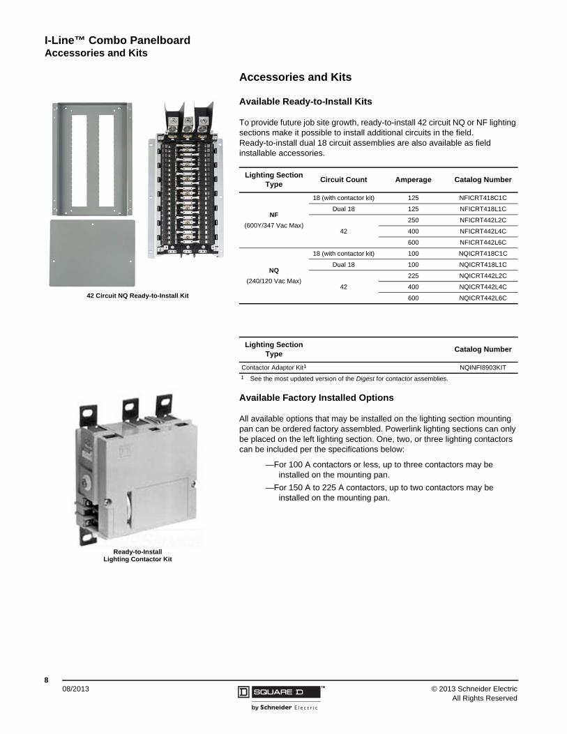
Available Ready-to-Install Kits
To provide future job site growth, ready-to-install 42 circuit NQ or NF lighting sections make it possible to install additional circuits in the field. Ready-to-install dual 18 circuit assemblies are also available as field installable accessories.
Available Factory Installed Options
All available options that may be installed on the lighting section mounting pan can be ordered factory assembled. Powerlink lighting sections can only be placed on the left lighting section. One, two, or three lighting contactors can be included per the specifications below:
—For 100 A contactors or less, up to three contactors may be installed on the mounting pan.
—For 150 A to 225 A contactors, up to two contactors may be installed on the mounting pan.
Lighting Section Type
Circuit Count Amperage Catalog Number
NF
(600Y/347 Vac Max)
18 (with contactor kit) 125 NFICRT418C1C
Dual 18 125 NFICRT418L1C
42
250 NFICRT442L2C
400 NFICRT442L4C
600 NFICRT442L6C
NQ
(240/120 Vac Max)
18 (with contactor kit) 100 NQICRT418C1C
Dual 18 100 NQICRT418L1C
42
225 NQICRT442L2C
400 NQICRT442L4C
600 NQICRT442L6C
Lighting Section Type
Catalog Number
Contactor Adaptor Kit1 NQINFI8903KIT
1 See the most updated version of the Digest for contactor assemblies.
42 Circuit NQ Ready-to-Install Kit
Ready-to-Install Lighting Contactor Kit
I-Line™ Combo PanelboardAccessories and Kits
908/2013™© 2013 Schneider Electric
All Rights Reserved
Accessories
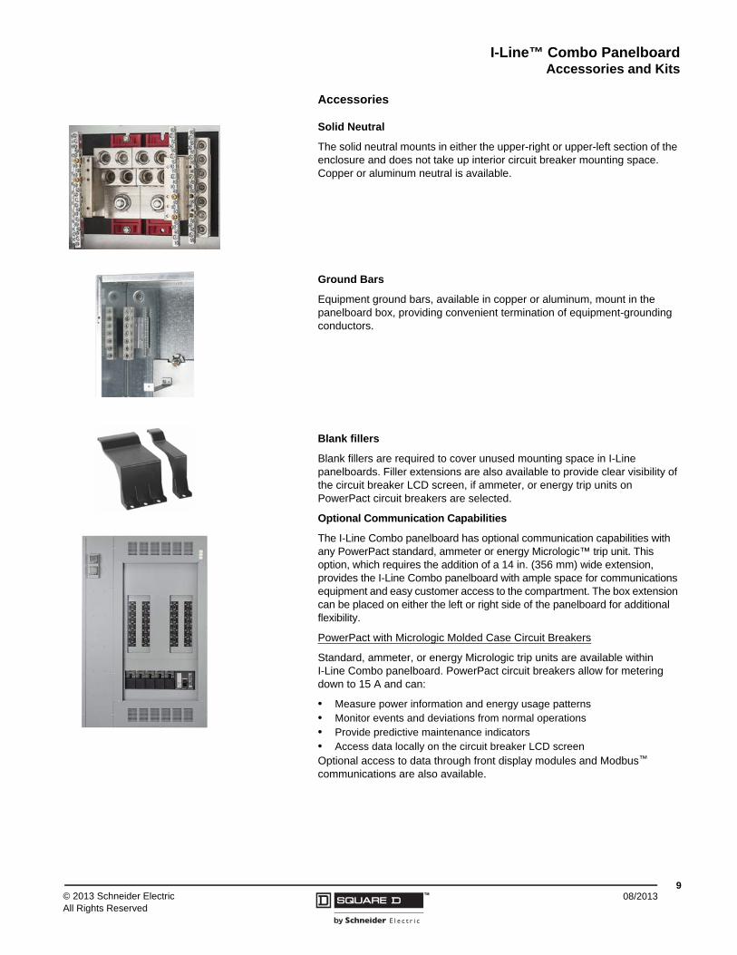
Solid Neutral
The solid neutral mounts in either the upper-right or upper-left section of the enclosure and does not take up interior circuit breaker mounting space. Copper or aluminum neutral is available.
Ground Bars
Equipment ground bars, available in copper or aluminum, mount in the panelboard box, providing convenient termination of equipment-grounding conductors.
Blank fillers
Blank fillers are required to cover unused mounting space in I-Line panelboards. Filler extensions are also available to provide clear visibility of the circuit breaker LCD screen, if ammeter, or energy trip units on PowerPact circuit breakers are selected.
Optional Communication Capabilities
The I-Line Combo panelboard has optional communication capabilities with any PowerPact standard, ammeter or energy Micrologic™ trip unit. This option, which requires the addition of a 14 in. (356 mm) wide extension, provides the I-Line Combo panelboard with ample space for communications equipment and easy customer access to the compartment. The box extension can be placed on either the left or right side of the panelboard for additional flexibility.
PowerPact with Micrologic Molded Case Circuit Breakers
Standard, ammeter, or energy Micrologic trip units are available within I-Line Combo panelboard. PowerPact circuit breakers allow for metering down to 15 A and can:
• Measure power information and energy usage patterns• Monitor events and deviations from normal operations• Provide predictive maintenance indicators• Access data locally on the circuit breaker LCD screenOptional access to data through front display modules and Modbus™ communications are also available.
I-Line™ Combo Panelboard General and Application Information
1008/2013 ™ © 2013 Schneider Electric
All Rights Reserved
General and Application Information
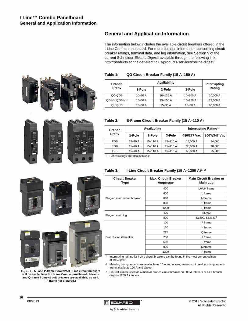
The information below includes the available circuit breakers offered in the I-Line Combo panelboard. For more detailed information concerning circuit breaker ratings, terminal data, and lug information, see Section 9 of the current Schneider Electric Digest, available through the following link: http://products.schneider-electric.us/products-services/online-digest/.
Table 1: QO Circuit Breaker Family (15 A–150 A)
Branch Prefix
Availability Interrupting Rating1-Pole 2-Pole 3-Pole
QO/QOB 10–70 A 10–125 A 10–100 A 10,000 A
QO-VH/QOB-VH 15–30 A 15–150 A 15–150 A 22,000 A
QH/QHB 15–30 A 15–30 A 15–30 A 65,000 A
Table 2: E-Frame Circuit Breaker Family (15 A–110 A)
Branch Prefix
Availability Interrupting Rating1
1-Pole 2-Pole 3-Pole 480/277 Vac 800Y/347 Vac
EDB 15–70 A 15–110 A 15–110 A 18,000 A 14,000
EGB 15–70 A 15–110 A 15–110 A 35,000 A 18,000
EJB 15–70 A 15–110 A 15–110 A 65,000 A 25,000
1 Series ratings are also available.
Table 3: I-Line Circuit Breaker Family (15 A–1200 A)1, 2
Circuit Breaker Type
Max. Circuit Breaker Amperage
Main Circuit Breaker or Main Lug
Plug-on main circuit breaker
400 LA/LH frame
600 L frame
800 M frame
800 P frame
1200 P frame
Plug-on main lug400 SL400
800 SL800, S339313
Branch circuit breaker
100 F frame
150 H frame
225 Q frame
250 J frame
600 L frame
800 M frame
1200 P frame
1 Interrupting ratings for I-Line circuit breakers can be found in the most current edition of the Digest.
2 Main lug configurations are available as 15 A and above; main circuit breaker configurations are available as 100 A and above.
3 S33931 can be used as a main or branch circuit breaker on 800 A interiors or as a branch only on 1200 A interiors.
H-, J-, L-, M- and P-frame PowerPact I-Line circuit breakers will be available in the I-Line Combo panelboard. F-frame and Q-frame I-Line circuit breakers are available, as well.
(F-frame not pictured.)
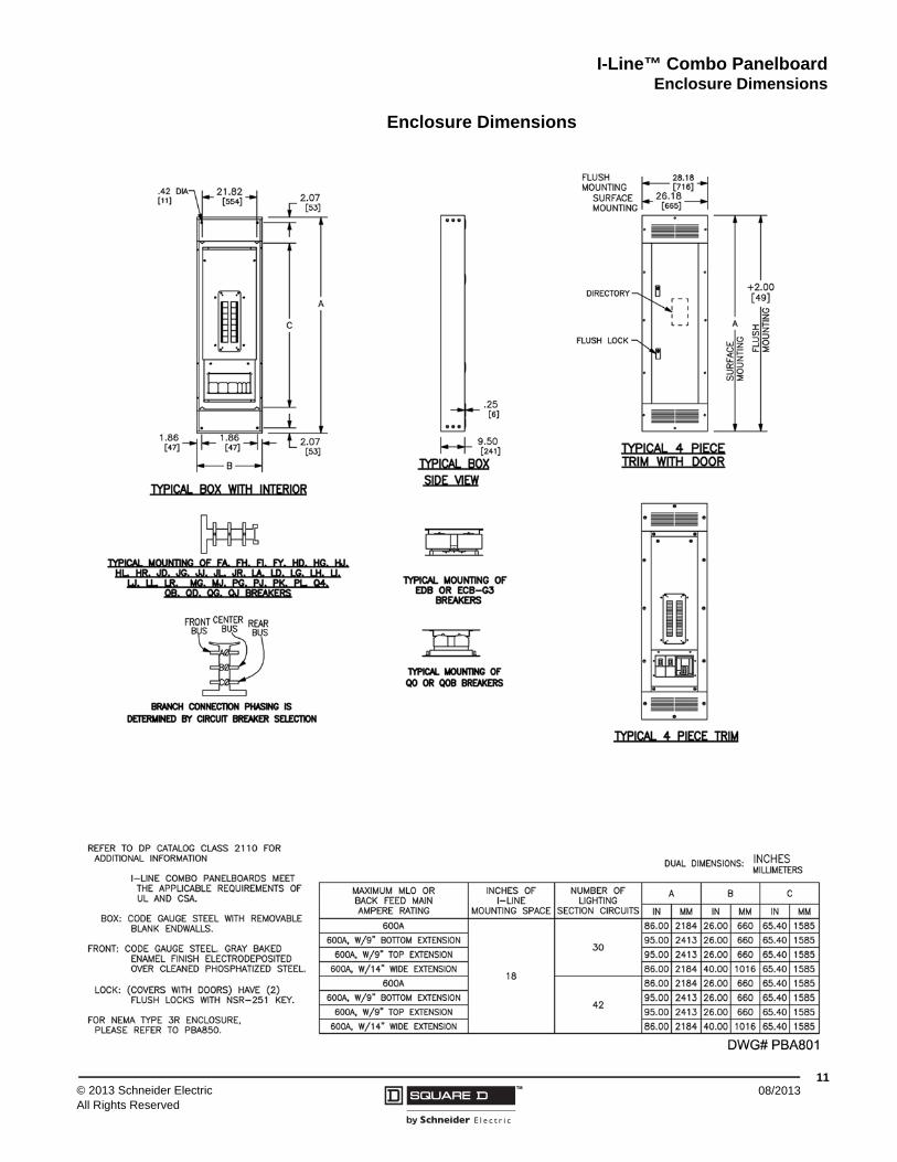
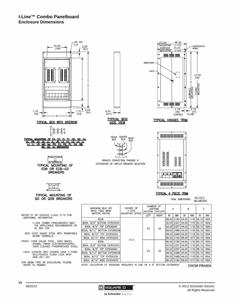
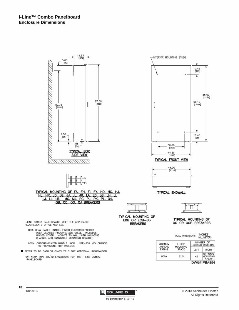
I-Line™ Combo PanelboardEnclosure Dimensions
1108/2013™© 2013 Schneider Electric
All Rights Reserved
Enclosure Dimensions
I-Line™ Combo Panelboard Enclosure Dimensions
1208/2013 ™ © 2013 Schneider Electric
All Rights Reserved
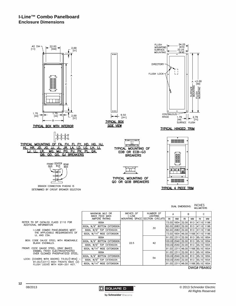
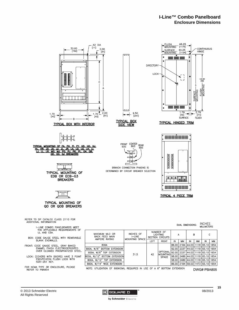
I-Line™ Combo PanelboardEnclosure Dimensions
1308/2013™© 2013 Schneider Electric
All Rights Reserved
I-Line™ Combo Panelboard Enclosure Dimensions
1408/2013 ™ © 2013 Schneider Electric
All Rights Reserved
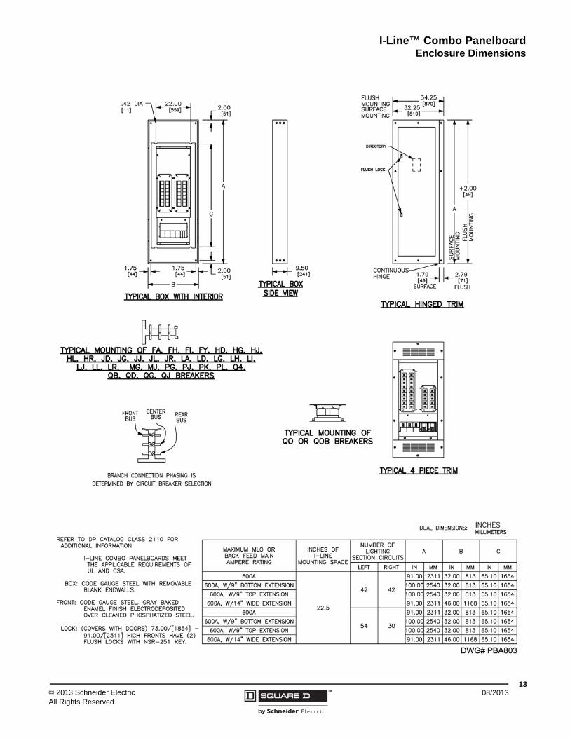
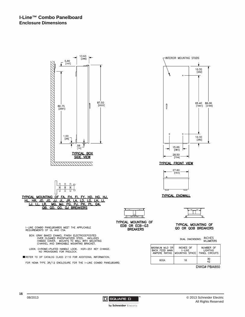
I-Line™ Combo PanelboardEnclosure Dimensions
1508/2013™© 2013 Schneider Electric
All Rights Reserved
I-Line™ Combo Panelboard Enclosure Dimensions
1608/2013 ™ © 2013 Schneider Electric
All Rights Reserved
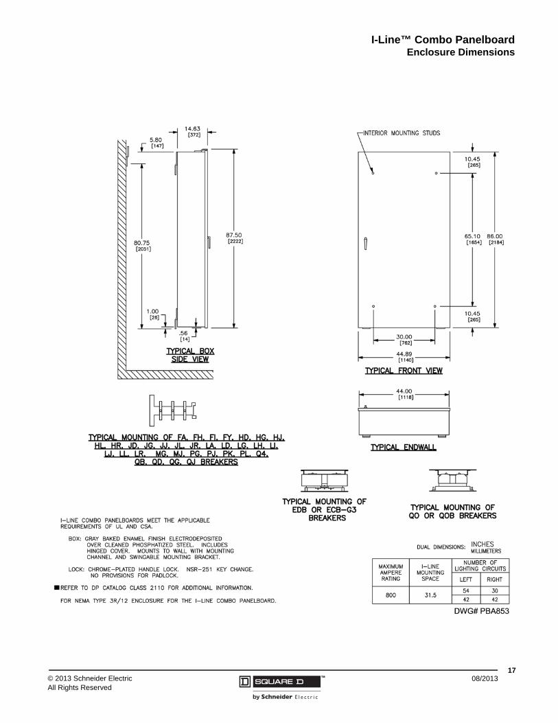
I-Line™ Combo PanelboardEnclosure Dimensions
1708/2013™© 2013 Schneider Electric
All Rights Reserved
I-Line™ Combo Panelboard Enclosure Dimensions
1808/2013 ™ © 2013 Schneider Electric
All Rights Reserved

I-Line™ Combo PanelboardReplacement Parts
1908/2013™© 2013 Schneider Electric
All Rights Reserved
Replacement Parts
I-Line Combo Panelboard Replacement Master Deadfront Assembly
Unit SizeUnit Assembly or Catalog Number
Replacement Deadfront Catalog Number
26 in. (660 mm)
wide
CP18864N3Q2C RPLCP18864N3Q2C
CP18864N3Q2 RPLCP18864N3Q2
CP18864N4Q2C RPLCP18864N4Q2C
CP18864N4Q2 RPLCP18864N4Q2
CP18864N3F2C RPLCP18864N3F2C
CP18864N3F2 RPLCP18864N4F2
CP18864N4F2C RPLCP18864N4F2C
CP18864N4F2 RPLCP18864N4F2
CP18866N3Q4C RPLCP18866N3Q4C
CP18866N4Q4C RPLCP18866N4Q4C
CP18866N3F4C RPLCP18866N3F4C
CP18866N4F4C RPLCP18866N4F4C
32 in.(813 mm)
wide
CP23734N3Q2C RPLCP23734N3Q2C
CP23734N3Q2 RPLCP23734N3Q2
CP23914N4Q2C RPLCP23914N4Q2C
CP23914N4Q2 RPLCP23914N4Q2
CP23914N5Q2C RPLCP23914N5Q2C
CP23914N5Q2 RPLCP23914N5Q2
CP23734N3F2C RPLCP23734N3F2C
CP23734N3F2 RPLCP23734N3F2
CP23914N4F2C RPLCP23914N4F2C
CP23914N4F2 RPLCP23914N4F2
CP23914N5F2C RPLCP23914N5F2C
CP23914N5F2 RPLCP23914N5F2
CP23736N3Q4C RPLCP23736N3Q4C
CP23916N4Q4C RPLCP23916N4Q4C
CP23916N5Q4C RPLCP23916N5Q4C
CP23736N3F4C RPLCP23736N3F4C
CP23916N4F4C RPLCP23916N4F4C
CP23916N5F4C RPLCP23916N5F4C
CP23916N44Q4C RPCP23916N44Q4C
CP23916N53Q4C RPCP23916N53Q4C
44 in. (1118 mm)
wide
CP32866N44Q4C RPCP32866N44Q4C
CP32866N53Q4C RPCP32866N53Q4C
CP32866N4BQ4C RPCP32866N4BQ4C
CP32866N44F4C RPCP32866N44F4C
CP32866N53F4C RPCP32866N53F4C
CP32866N4BF4C RPCP32866N4BF4C
CP32868N44Q6C RPCP32868N44Q6C
CP32868N53Q6C RPCP32868N53Q6C
CP32868N3BQ6C RPCP32868N3BQ6C
CP32868N4BQ6C RPCP32868N4BQ6C
CP32868N5BQ6C RPCP32868N5BQ6C
CP32868N44F6C RPCP32868N44F6C
CP32868N53F6C RPCP32868N53F6C

08/2013
Schneider Electric USA, Inc.1415 S. Roselle RoadPalatine, IL 60067 USA1-888-778-2733www.schneider-electric.us
© 2013 Schneider Electric All Rights ReservedI-Line™, Micrologic™, Modbus™, Powerlink™, PowerPact™, and Square D™ are trademarks owned by Schneider Electric Industries SAS or its affiliated companies. All other trademarks are the property of their respective owners.
2110CT1301