HMI User guide
34
RTU560 Remote Terminal Unit Integrated HMI, Users Guide Contents: This manual describes the Web-based HMI implementation of the RTU560.
-
Upload
patel-ashok -
Category
Documents
-
view
223 -
download
0
Transcript of HMI User guide
7/29/2019 HMI User guide
http://slidepdf.com/reader/full/hmi-user-guide 1/34
RTU560 Remote Terminal Unit
Integrated HMI, Users Guide
Contents: This manual describes the Web-based HMI implementation of theRTU560.

7/29/2019 HMI User guide
http://slidepdf.com/reader/full/hmi-user-guide 2/34
7/29/2019 HMI User guide
http://slidepdf.com/reader/full/hmi-user-guide 3/34
Revision
Document number: 1KGT 150 563 V002 1
Revision Date Description
0 07/2005 Initial version
1 04/2007 Adaptations to Windows XPStarting up the HMI Client
2 08/2007 Format cleanupChapter ‘Process archive list’ updatedChapter ‘Alarm list’ updatedChapter ‘Performing controls’ renamed to ‘Controllablecomponents’ and updated
We reserve all rights in this document and the information containing therein.Reproduction, use or disclosure to third parties without permission is strictly
forbidden
© Copyright 2007 ABB AG, Mannheim/Germany
ABB AG 1KGT 150 563 V002 1 I

7/29/2019 HMI User guide
http://slidepdf.com/reader/full/hmi-user-guide 4/34
7/29/2019 HMI User guide
http://slidepdf.com/reader/full/hmi-user-guide 5/34
Contents
Revision ............................................................................................ I Contents.......................................................................................... III Abbreviations .................................................................................. V 1 Introduction............................................................................ 1-1 2 General Information............................................................... 2-1
..........................................................2-1 2.1 Starting the HMI Application ..................................... 2-1 2.2 Starting the HMI from the user’s desktop .................................................................................2-2 2.3 The Start Page ...............................................................................2-3
2.4 Menu item ‘Info’ .............................................................................2-3 2.5 Menu item ‘Main’ ..........................................................................2-4 2.6 User Authorization .................................................................2-4 2.7 Normal Log In / Log Out .................................... 2-5 2.8 Normal termination of the Integrated HMI ................................ 2-5 2.9 Abnormal termination of the Integrated HMI
2.10 ............................................................................2-6 Control Authority
2.11 ..............................................................2-7 Navigating through pages
3 Controllable components...................................................... 3-1 .............................................................................................3-1 3.1 General .........................................................................3-1 3.1.1 Visualization
........................................................................3-1 3.1.2 Authorization ....................................................3-2 3.1.3 Preconfigured commands ................................. 3-3 3.2 Single and Double Commands (SCO, DCO) ..................................3-3 3.2.1 Performing user selected commands ....................................................3-4 3.3 Tap Position Commands (RCO) ..................................3-4 3.3.1 Performing user selected commands .................................. 3-5 3.4 Normalized Value Commands (ASO, DSO) ..................................3-5 3.4.1 Performing user selected commands ..........................................................3-6 3.5 Bit String Commands (BSO) ..................................3-6 3.5.1 Performing user selected commands
4 Additional Representations.................................................. 4-1 ..............................................................4-1 4.1 History Table Component ................................................................................4-1 4.2 System-Events ..................................................................................4-2 4.3 Date and Time
5 Process Archive list .............................................................. 5-1 .............................................................................................5-1 5.1 General ...................... 5-1 5.2 Usage of process archive with Interval download .................................................5-1 5.2.1 Control and Information Bar ................... 5-2 5.3 Usage of process archive with complete download .................................................5-2 5.3.1 Control and Information Bar ...............................................................5-3 5.3.2 Filter setting dialog .................................. 5-3 5.4 Representation of process archive entries
6 Alarm list ................................................................................ 6-1 ABB AG 1KGT 150 563 V002 1 III
7/29/2019 HMI User guide
http://slidepdf.com/reader/full/hmi-user-guide 6/34
Contents Integrated HMI, Users Guide
.............................................................................................6-1 6.1 General .........................................................................................6-1 6.2 Operation ...........................................................................6-1 6.2.1 Control Bar ...............................................................6-1 6.2.2 Acknowledgement ................................................................6-2 6.3 Runtime Representation
ABB AG 1KGT 150 563 V002 1 IV
7/29/2019 HMI User guide
http://slidepdf.com/reader/full/hmi-user-guide 7/34
Abbreviations
CMU Communication and Data Processing Unit
AMI Analog Measured value Input
ASO Analog Set point command Output
BCU Bus Connection Unit
BSI Bit String Input (8, 16 bit)
BSO Bit String Output (1, 2, 8, 16 bit)
CS Control System
CSC Command Supervision Channel
CS-Command Clock Synch Command
CRC Cyclic Redundancy Check
CTO Common Time Object
DCO Double Command Output
DMI Digital Measured value Input (8, 16 bit)
DPI Double Point Input
DSO Digital Set point command Output (8, 16 bit)
EPI Event of Protection equipment Input (1bit)
GCD General Configuration Data
HCI Host Communication Interface
IED Intelligent Electronic Device
IIN Internal Indication
IOC I/O Controller (Controller on I/O Board)
IOD Input Output Data
IOM I/O Bus Master (Function of SLC)
ITI Integrated Totals Input
MFI Analog Measured value Floating Input
MPU Main Processing Unit
NCC Network Control Center
PB Peripheral Bus
PBP Peripheral Bus Processor
PDP Process Data Processing
PLC Programmable Logic Control
PPP Point to Point Protocol
PSU Power Supply Unit
RCO Regulation step Command Output
RTC Real Time ClockSBO Select Before Operate
SCADA Supervision, Control and Data Acquisition
ABB AG 1KGT 150 563 V002 1 V
7/29/2019 HMI User guide
http://slidepdf.com/reader/full/hmi-user-guide 8/34
Abbreviations Integrated HMI, Users Guide
SCI Sub-Device Communication Interface
SCO Single Command Output
SEV System Events
SLC Serial Line Controller
SOC Strobe Output Channel
SOE Sequence-of-Event Queue
SPI Single Point Input
STI Step position Input (8 bit)
TSI Time Synch Input
TSO Time Synch Output
ABB AG 1KGT 150 563 V002 1 VI
7/29/2019 HMI User guide
http://slidepdf.com/reader/full/hmi-user-guide 9/34
1 Introduction
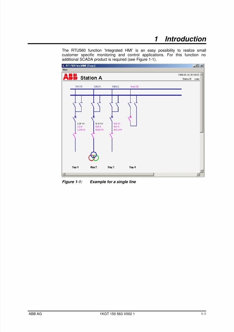
The RTU560 function ’Integrated HMI’ is an easy possibility to realize smallcustomer specific monitoring and control applications. For this function no
additional SCADA product is required (see Figure 1-1).
Figure 1-1: Example for a single line
ABB AG 1KGT 150 563 V002 1 1-1

7/29/2019 HMI User guide
http://slidepdf.com/reader/full/hmi-user-guide 10/34
7/29/2019 HMI User guide
http://slidepdf.com/reader/full/hmi-user-guide 11/34
2 General Information
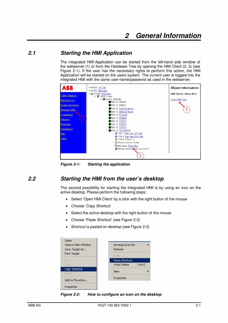
2.1 Starting the HMI Application
The integrated HMI-Application can be started from the left-hand side window ofthe webserver (1) or from the Hardware Tree by opening the HMI Client (2, 3) (seeFigure 2-1). If the user has the necessary rights to perform this action, the HMIApplication will be started on the users system. The current user is logged into theintegrated HMI with the same user-name/password as used in the webserver.
Figure 2-1: Starting the application
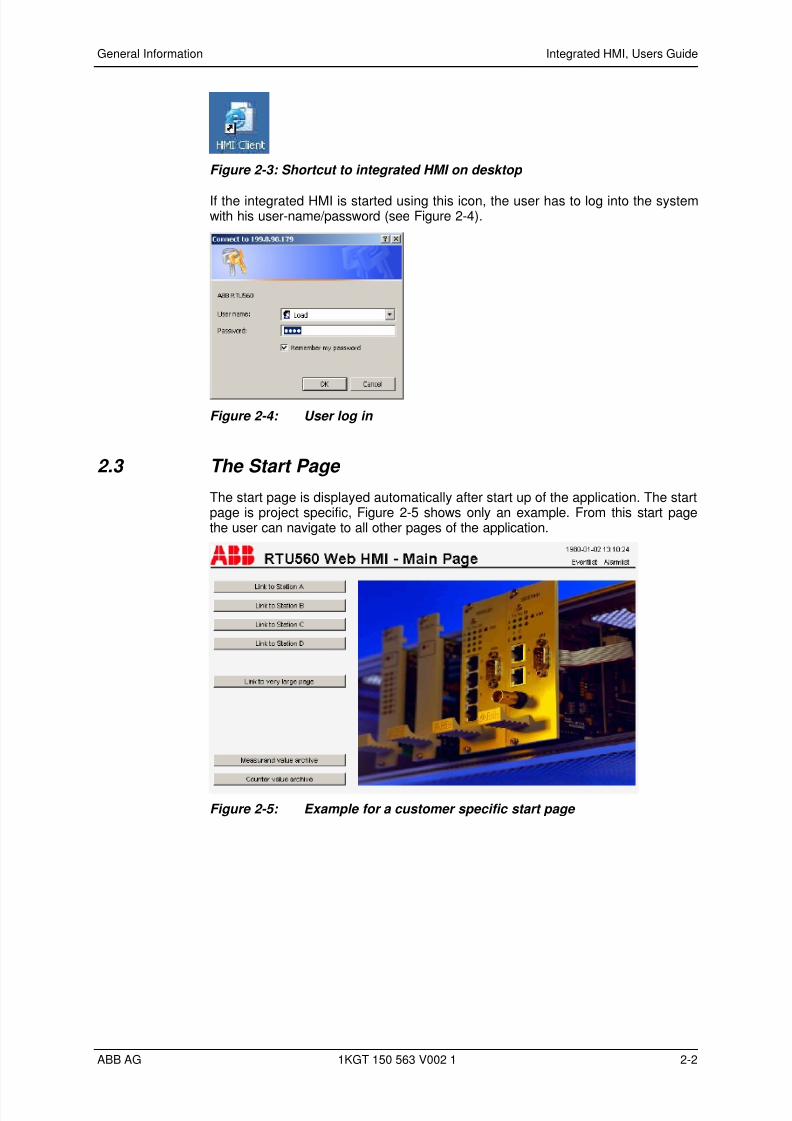
2.2 Starting the HMI from the user’s desktop
The second possibility for starting the integrated HMI is by using an icon on theactive desktop. Please perform the following steps:
• Select ‘Open HMI Client’ by a click with the right button of the mouse
• Choose ‘Copy Shortcut’
• Select the active desktop with the right button of the mouse
Figure 2-2)• Choose ‘Paste Shortcut’ (see
• Shortcut is pasted on desktop (see Figure 2-3)
Figure 2-2: How to configure an icon on the desktop
ABB AG 1KGT 150 563 V002 1 2-1
7/29/2019 HMI User guide
http://slidepdf.com/reader/full/hmi-user-guide 12/34
7/29/2019 HMI User guide
http://slidepdf.com/reader/full/hmi-user-guide 13/34
General Information Integrated HMI, Users Guide
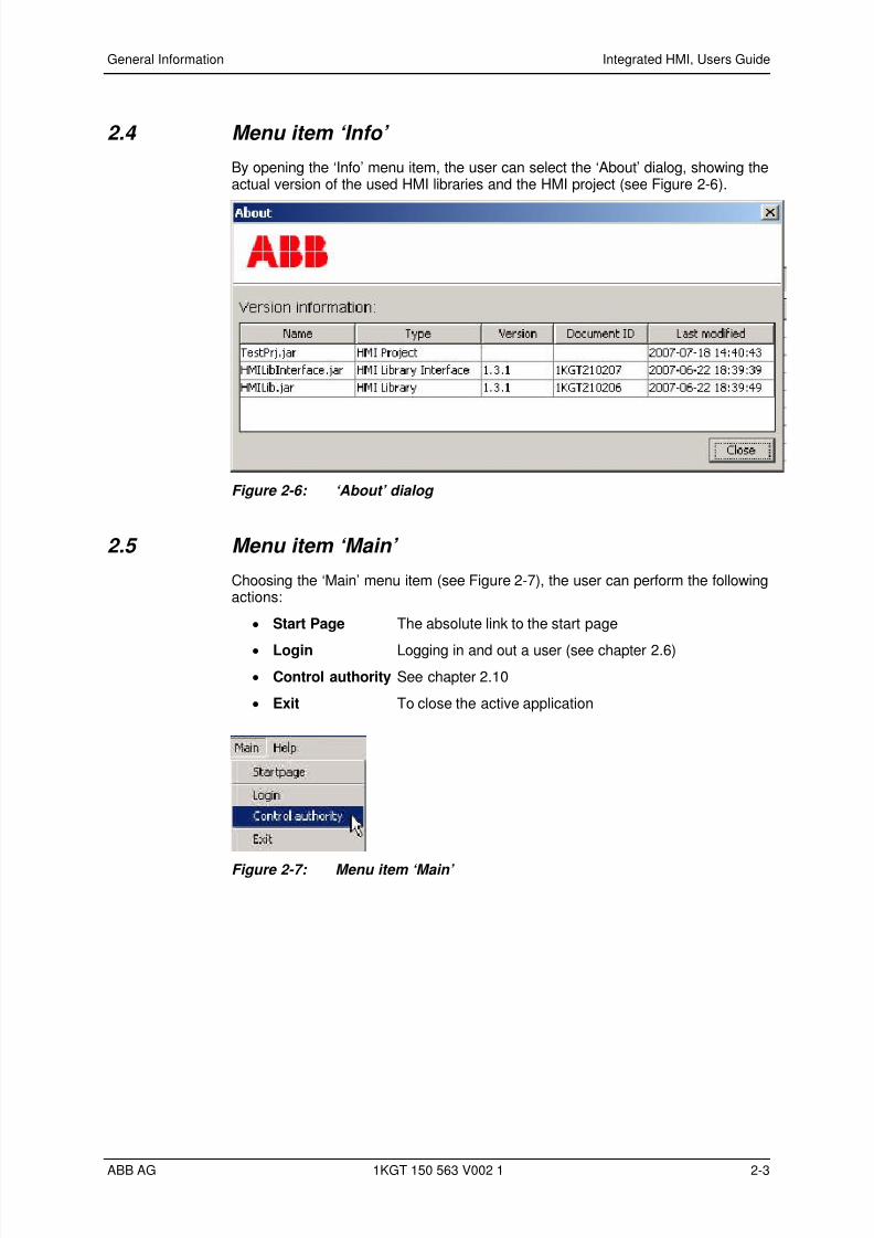
2.4 Menu item ‘Info’
By opening the ‘Info’ menu item, the user can select the ‘About’ dialog, showing theactual version of the used HMI libraries and the HMI project (see Figure 2-6).
Figure 2-6: ‘About’ dialog
2.5 Menu item ‘Main’
Choosing the ‘Main’ menu item (see Figure 2-7), the user can perform the followingactions:
Start Page The absolute link to the start page•
Login Logging in and out a user (see chapter 2.6)•
Control authority See chapter 2.10 •
Exit To close the active application•
Figure 2-7: Menu item ‘Main’
ABB AG 1KGT 150 563 V002 1 2-3
7/29/2019 HMI User guide
http://slidepdf.com/reader/full/hmi-user-guide 14/34
General Information Integrated HMI, Users Guide
2.6 User Authorization
A user needs the necessary privileges to start the Integrated HMI and he needsadditional privileges to perform process commands. For this reason a user has tolog in to the system with username and password.
Users and their passwords are administrated in the RTU560Webserver. The initialvalues are the same as for the Webserver (see document ’Webserver Release 7’):
Admin / Admin• Administrator functions
Control / Control (*) • Operator may perform test commands
Operator / Operator • Operator may perform commands
View / View• Operator can supervise the process
Load / Load• Operator can load configuration files (*)
(*) Available only in RTU560 Web Server
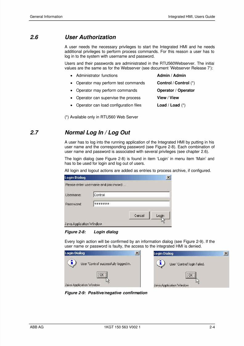
2.7 Normal Log In / Log Out
A user has to log into the running application of the Integrated HMI by putting in hisuser name and the corresponding password (see Figure 2-8). Each combination ofuser name and password is associated with several privileges (see chapter 2.6).
The login dialog (see Figure 2-8) is found in item ‘Login’ in menu item ‘Main’ andhas to be used for login and log out of users.
All login and logout actions are added as entries to process archive, if configured.
Figure 2-8: Login dialog
Every login action will be confirmed by an information dialog (see Figure 2-9). If theuser name or password is faulty, the access to the integrated HMI is denied.
Figure 2-9: Positive/negative confirmation
ABB AG 1KGT 150 563 V002 1 2-4

7/29/2019 HMI User guide
http://slidepdf.com/reader/full/hmi-user-guide 15/34
General Information Integrated HMI, Users Guide
The log out action will also be acknowledged (see Figure 2-10).
Figure 2-10: Logging out of the application
2.8 Normal termination of the Integrated HMI
The user can terminate the active session by choosing ‘Exit’ in ‘Main’ menu item.
After the necessary confirmation (see Figure 2-11) the connection is closed, andthe control authority will go back to the connected hosts (see also chapter 2.10).
Figure 2-11: Verification of the Exit command
2.9 Abnormal termination of the Integrated HMI Normally the user will exit the Integrated HMI by operation. In case of an error (e.g.Ethernet communication is lost) the HMI Server will close the connection. Aninformation is shown on the client screen (see Figure 2-12).
Figure 2-12: Abnormal termination of the integrated HMI
ABB AG 1KGT 150 563 V002 1 2-5
7/29/2019 HMI User guide
http://slidepdf.com/reader/full/hmi-user-guide 16/34
General Information Integrated HMI, Users Guide
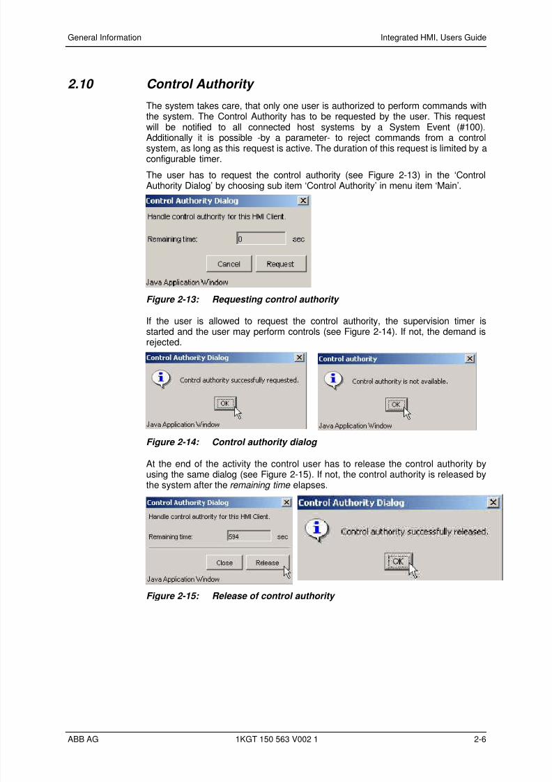
2.10 Control Authority
The system takes care, that only one user is authorized to perform commands withthe system. The Control Authority has to be requested by the user. This requestwill be notified to all connected host systems by a System Event (#100).
Additionally it is possible -by a parameter- to reject commands from a controlsystem, as long as this request is active. The duration of this request is limited by aconfigurable timer.
The user has to request the control authority (see Figure 2-13) in the ‘ControlAuthority Dialog’ by choosing sub item ‘Control Authority’ in menu item ‘Main’.
Figure 2-13: Requesting control authority
If the user is allowed to request the control authority, the supervision timer isstarted and the user may perform controls (see Figure 2-14). If not, the demand isrejected.
Figure 2-14: Control authority dialog
At the end of the activity the control user has to release the control authority byusing the same dialog (see Figure 2-15). If not, the control authority is released bythe system after the elapses.remaining time
Figure 2-15: Release of control authority
ABB AG 1KGT 150 563 V002 1 2-6

7/29/2019 HMI User guide
http://slidepdf.com/reader/full/hmi-user-guide 17/34
General Information Integrated HMI, Users Guide
2.11 Navigating through pages
In the Integrated HMI there are two features available to navigate through thepages of the application:
•
Link Button• Link Label
Figure 2-16: Example of link label and link button
The features of both components are defined during data entry, but bothcomponents will navigate to a specific page of the application. The Link Label willchange his color while touching with the mouse cursor and the cursor will changeto another symbol.
ABB AG 1KGT 150 563 V002 1 2-7

7/29/2019 HMI User guide
http://slidepdf.com/reader/full/hmi-user-guide 18/34
7/29/2019 HMI User guide
http://slidepdf.com/reader/full/hmi-user-guide 19/34
3 Controllable components
3.1 General
3.1.1 Visualization
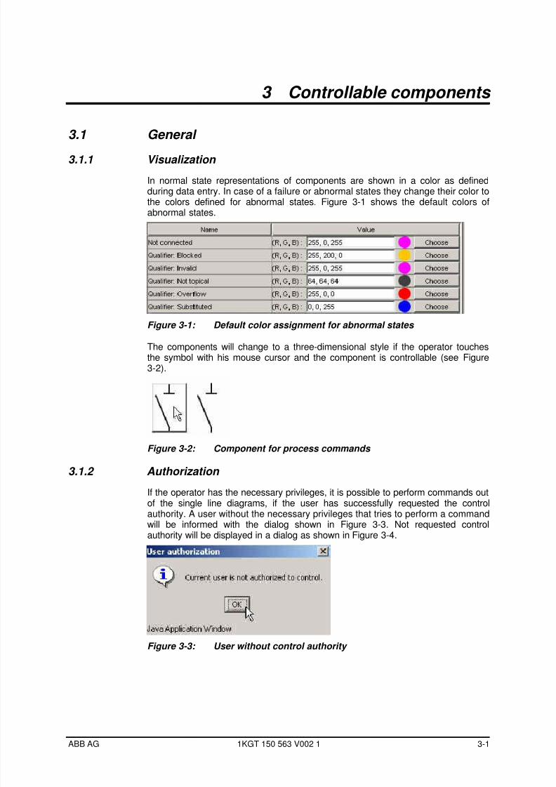
In normal state representations of components are shown in a color as definedduring data entry. In case of a failure or abnormal states they change their color tothe colors defined for abnormal states. Figure 3-1 shows the default colors ofabnormal states.
Figure 3-1: Default color assignment for abnormal states
The components will change to a three-dimensional style if the operator touchesthe symbol with his mouse cursor and the component is controllable (see Figure3-2).
Figure 3-2: Component for process commands
3.1.2 Authorization
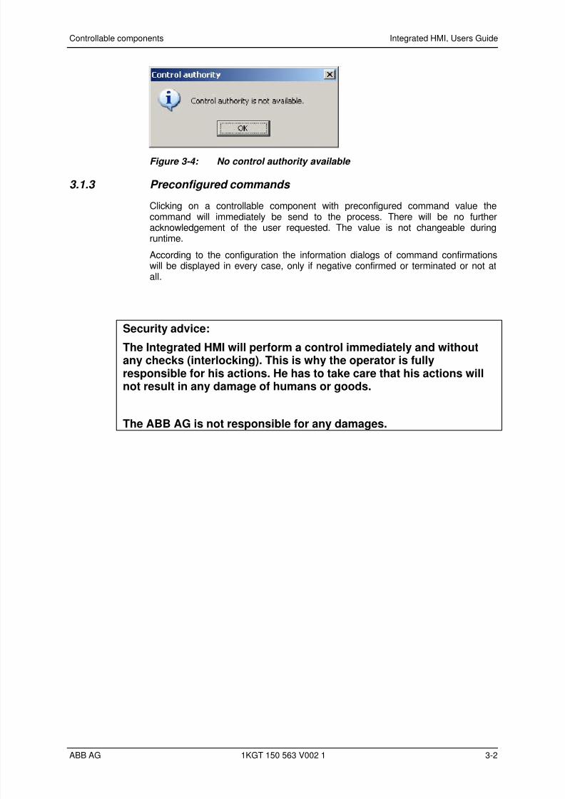
If the operator has the necessary privileges, it is possible to perform commands outof the single line diagrams, if the user has successfully requested the controlauthority. A user without the necessary privileges that tries to perform a commandwill be informed with the dialog shown in Figure 3-3. Not requested controlauthority will be displayed in a dialog as shown in Figure 3-4.
Figure 3-3: User without control authority
ABB AG 1KGT 150 563 V002 1 3-1
7/29/2019 HMI User guide
http://slidepdf.com/reader/full/hmi-user-guide 20/34
Controllable components Integrated HMI, Users Guide
Figure 3-4: No control authority available
3.1.3 Preconfigured commands
Clicking on a controllable component with preconfigured command value thecommand will immediately be send to the process. There will be no furtheracknowledgement of the user requested. The value is not changeable duringruntime.
According to the configuration the information dialogs of command confirmationswill be displayed in every case, only if negative confirmed or terminated or not at
all.
Security advice:
The Integrated HMI will perform a control immediately and withoutany checks (interlocking). This is why the operator is fullyresponsible for his actions. He has to take care that his actions willnot result in any damage of humans or goods.
The ABB AG is not responsible for any damages.
ABB AG 1KGT 150 563 V002 1 3-2
7/29/2019 HMI User guide
http://slidepdf.com/reader/full/hmi-user-guide 21/34
Controllable components Integrated HMI, Users Guide
3.2 Single and Double Commands (SCO, DCO)
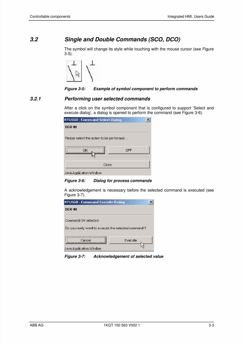
The symbol will change its style while touching with the mouse cursor (see Figure3-5).
Figure 3-5: Example of symbol component to perform commands
3.2.1 Performing user selected commands
After a click on the symbol component that is configured to support ‘Select andexecute dialog’, a dialog is opened to perform the command (see Figure 3-6).
Figure 3-6: Dialog for process commands
A acknowledgement is necessary before the selected command is executed (seeFigure 3-7).
Figure 3-7: Acknowledgement of selected value
ABB AG 1KGT 150 563 V002 1 3-3
7/29/2019 HMI User guide
http://slidepdf.com/reader/full/hmi-user-guide 22/34
Controllable components Integrated HMI, Users Guide
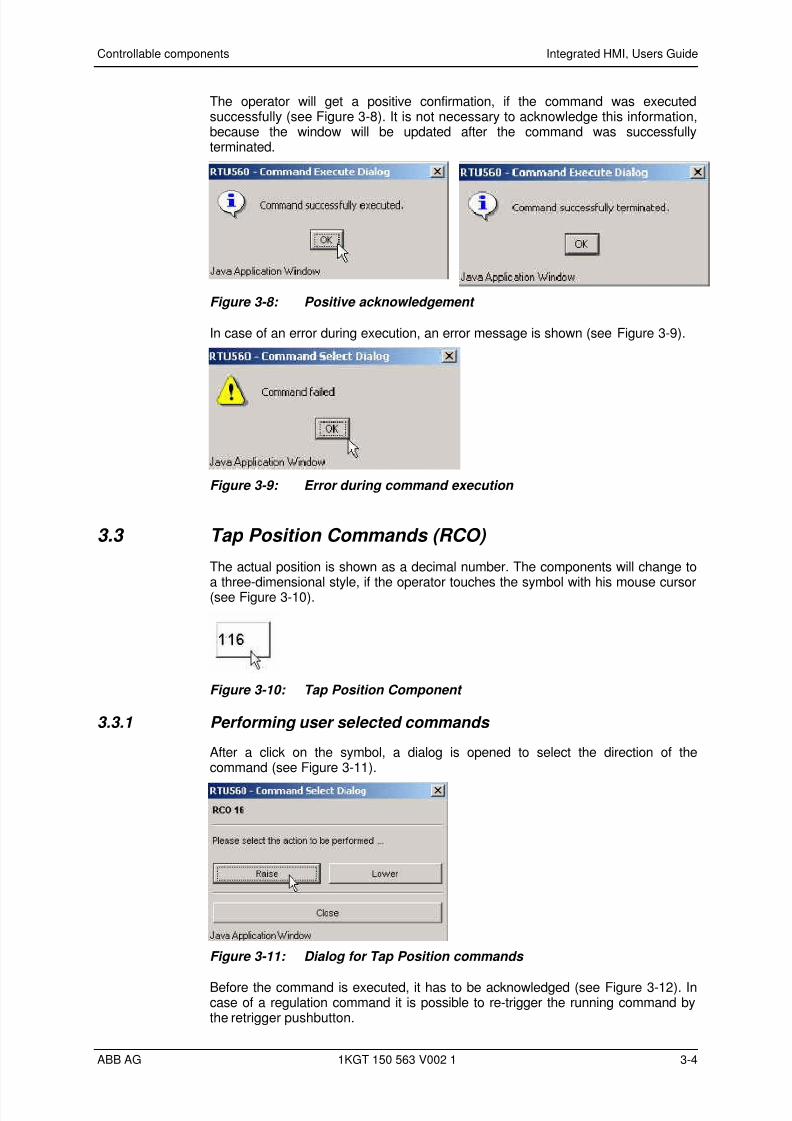
The operator will get a positive confirmation, if the command was executedsuccessfully (see Figure 3-8). It is not necessary to acknowledge this information,because the window will be updated after the command was successfullyterminated.
Figure 3-8: Positive acknowledgement
In case of an error during execution, an error message is shown (see Figure 3-9).
Figure 3-9: Error during command execution
3.3 Tap Position Commands (RCO)
The actual position is shown as a decimal number. The components will change to
a three-dimensional style, if the operator touches the symbol with his mouse cursor(see Figure 3-10).
Figure 3-10: Tap Position Component
3.3.1 Performing user selected commands
After a click on the symbol, a dialog is opened to select the direction of thecommand (see Figure 3-11).
Figure 3-11: Dialog for Tap Position commands
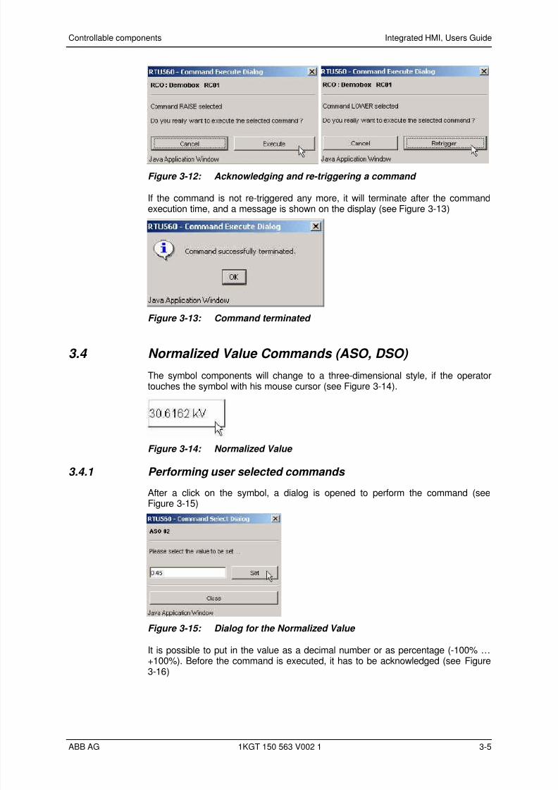
Before the command is executed, it has to be acknowledged (see Figure 3-12). Incase of a regulation command it is possible to re-trigger the running command bythe retrigger pushbutton.
ABB AG 1KGT 150 563 V002 1 3-4
7/29/2019 HMI User guide
http://slidepdf.com/reader/full/hmi-user-guide 23/34
Controllable components Integrated HMI, Users Guide
Figure 3-12: Acknowledging and re-triggering a command
If the command is not re-triggered any more, it will terminate after the commandexecution time, and a message is shown on the display (see Figure 3-13)
Figure 3-13: Command terminated
3.4 Normalized Value Commands (ASO, DSO)
The symbol components will change to a three-dimensional style, if the operatortouches the symbol with his mouse cursor (see Figure 3-14).
Figure 3-14: Normalized Value
3.4.1 Performing user selected commands
After a click on the symbol, a dialog is opened to perform the command (seeFigure 3-15)
Figure 3-15: Dialog for the Normalized Value
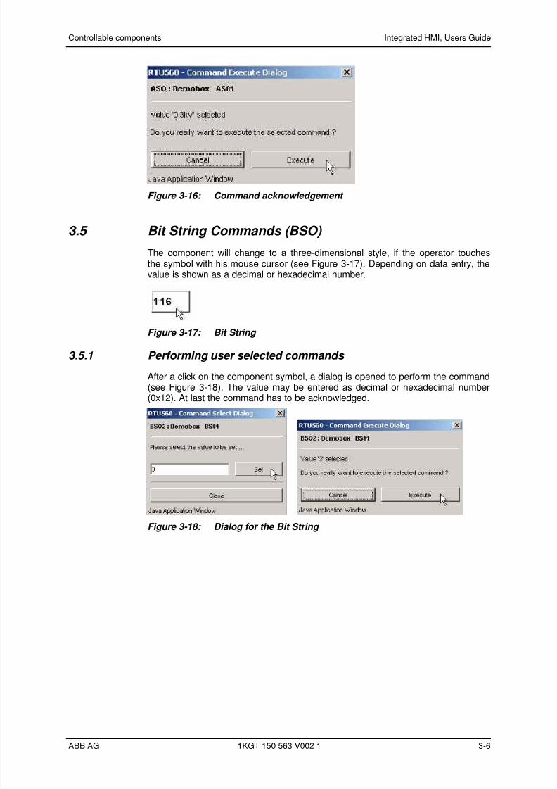
It is possible to put in the value as a decimal number or as percentage (-100% …+100%). Before the command is executed, it has to be acknowledged (see Figure3-16)
ABB AG 1KGT 150 563 V002 1 3-5
7/29/2019 HMI User guide
http://slidepdf.com/reader/full/hmi-user-guide 24/34
Controllable components Integrated HMI, Users Guide
Figure 3-16: Command acknowledgement
3.5 Bit String Commands (BSO)
The component will change to a three-dimensional style, if the operator touchesthe symbol with his mouse cursor (see Figure 3-17). Depending on data entry, the
value is shown as a decimal or hexadecimal number.
Figure 3-17: Bit String
3.5.1 Performing user selected commands
After a click on the component symbol, a dialog is opened to perform the command(see Figure 3-18). The value may be entered as decimal or hexadecimal number(0x12). At last the command has to be acknowledged.
Figure 3-18: Dialog for the Bit String
ABB AG 1KGT 150 563 V002 1 3-6
7/29/2019 HMI User guide
http://slidepdf.com/reader/full/hmi-user-guide 25/34
4 Additional Representations
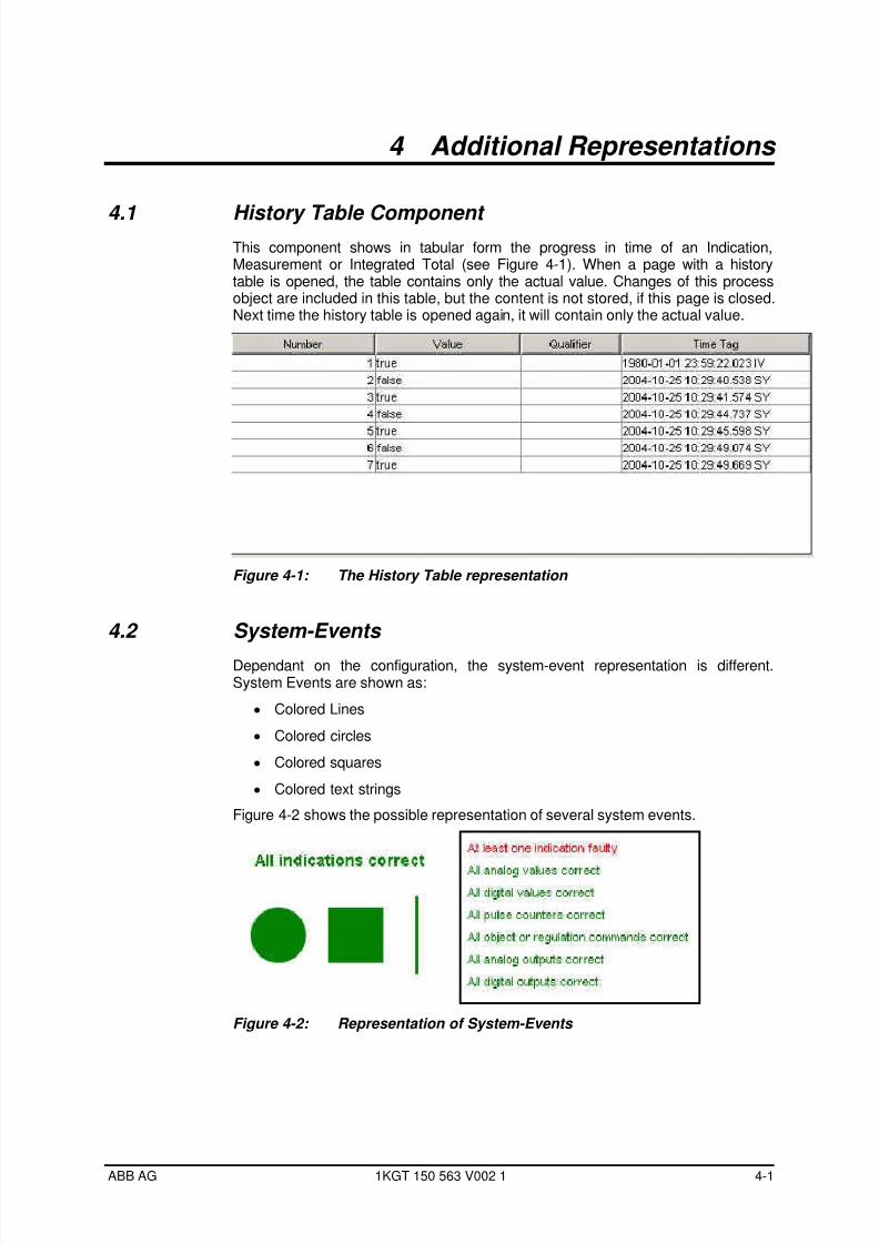
4.1 History Table Component This component shows in tabular form the progress in time of an Indication,Measurement or Integrated Total (see Figure 4-1). When a page with a historytable is opened, the table contains only the actual value. Changes of this processobject are included in this table, but the content is not stored, if this page is closed.Next time the history table is opened again, it will contain only the actual value.
Figure 4-1: The History Table representation
4.2 System-Events
Dependant on the configuration, the system-event representation is different.System Events are shown as:
• Colored Lines
• Colored circles
• Colored squares
• Colored text strings
Figure 4-2 shows the possible representation of several system events.
Figure 4-2: Representation of System-Events
ABB AG 1KGT 150 563 V002 1 4-1
7/29/2019 HMI User guide
http://slidepdf.com/reader/full/hmi-user-guide 26/34
7/29/2019 HMI User guide
http://slidepdf.com/reader/full/hmi-user-guide 27/34
5 Process Archive list
5.1 General The RTU560 supports three types of process archives:
• Measurement value archive
• Counter value archive
• Event archive
The process archive list component can be configured to download the processarchive of RTU560 in intervals of 50 entries or completely. The representation ofthe contents of process archives is not influenced by the configured download type.
The process archive list is not updated automatically during runtime, but has to be
activated by the user.
5.2 Usage of process archive with Interval download
If process archive is managed by Integrated HMI on basis of intervals only 50entries are downloaded to the HMI Application at a time.
5.2.1 Control and Information Bar
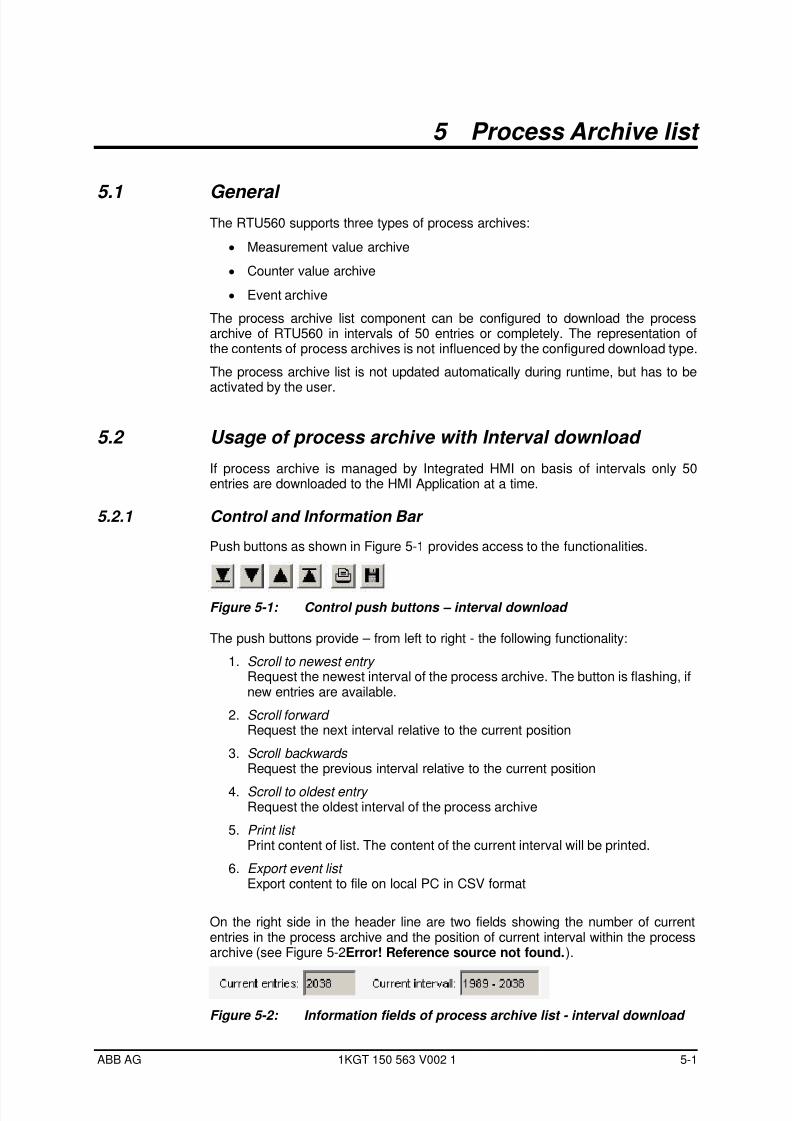
Push buttons as shown in Figure 5-1 provides access to the functionalities.
Figure 5-1: Control push buttons – interval download
The push buttons provide – from left to right - the following functionality:
1. Scroll to newest entry Request the newest interval of the process archive. The button is flashing, ifnew entries are available.
2. Scroll forward Request the next interval relative to the current position
3. Scroll backwards Request the previous interval relative to the current position
4. Scroll to oldest entry Request the oldest interval of the process archive
5. Print list Print content of list. The content of the current interval will be printed.
6. Export event list Export content to file on local PC in CSV format
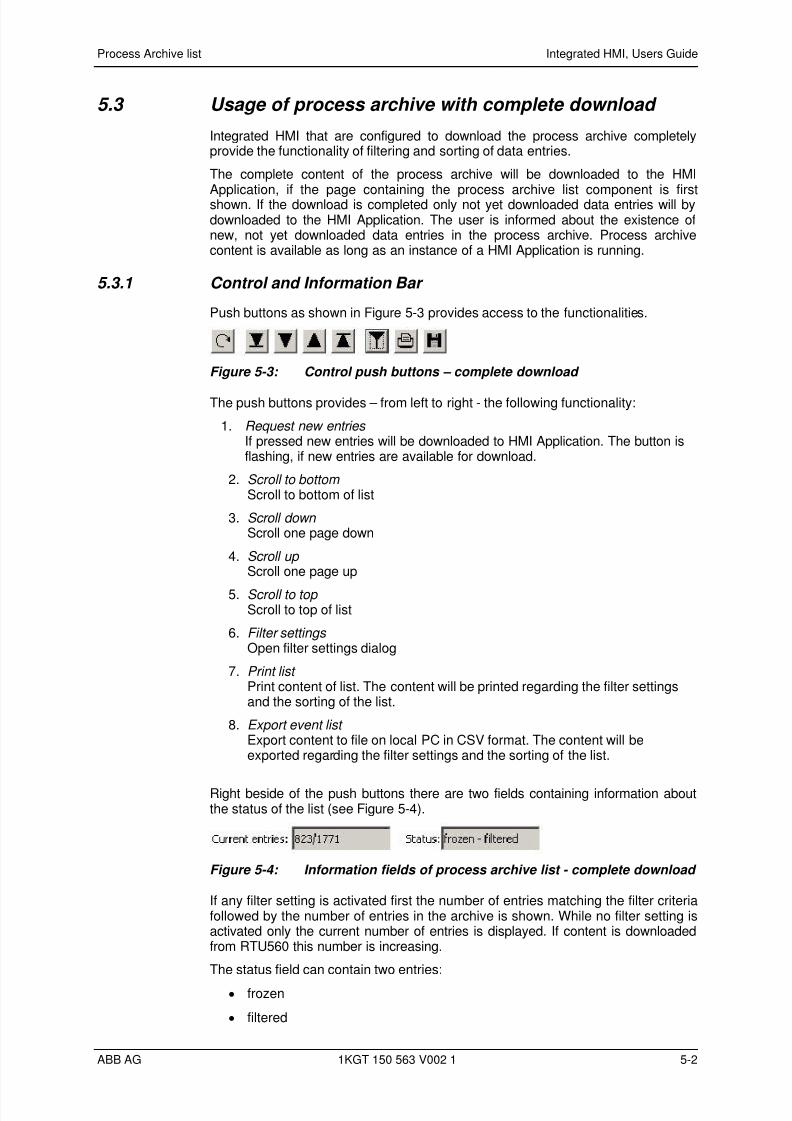
On the right side in the header line are two fields showing the number of currententries in the process archive and the position of current interval within the processarchive (see Figure 5-2Error! Reference source not found.).
Figure 5-2: Information fields of process archive list - interval download
ABB AG 1KGT 150 563 V002 1 5-1
7/29/2019 HMI User guide
http://slidepdf.com/reader/full/hmi-user-guide 28/34
7/29/2019 HMI User guide
http://slidepdf.com/reader/full/hmi-user-guide 29/34
Process Archive list Integrated HMI, Users Guide
‘Frozen’ signalizes that there are new entries waiting for download to HMIApplication and ‘filtered’ is shown while any filter setting is active.
5.3.2 Filter setting dialog
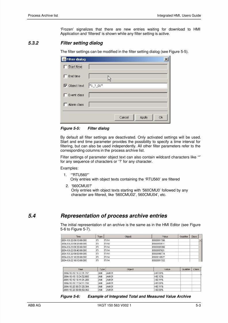
The filter settings can be modified in the filter setting dialog (see Figure 5-5).
Figure 5-5: Filter dialog
By default all filter settings are deactivated. Only activated settings will be used.Start and end time parameter provides the possibility to specify a time interval forfiltering, but can also be used independently. All other filter parameters refer to thecorresponding columns in the process archive list.
Filter settings of parameter object text can also contain wildcard characters like ‘*’for any sequence of characters or ‘?’ for any character.
Examples:1. ‘*RTU560*’
Only entries with object texts containing the ‘RTU560’ are filtered
2. ‘560CMU0?’Only entries with object texts starting with ‘560CMU0’ followed by anycharacter are filtered, like ‘560CMU02’, 560CMU04’, etc.
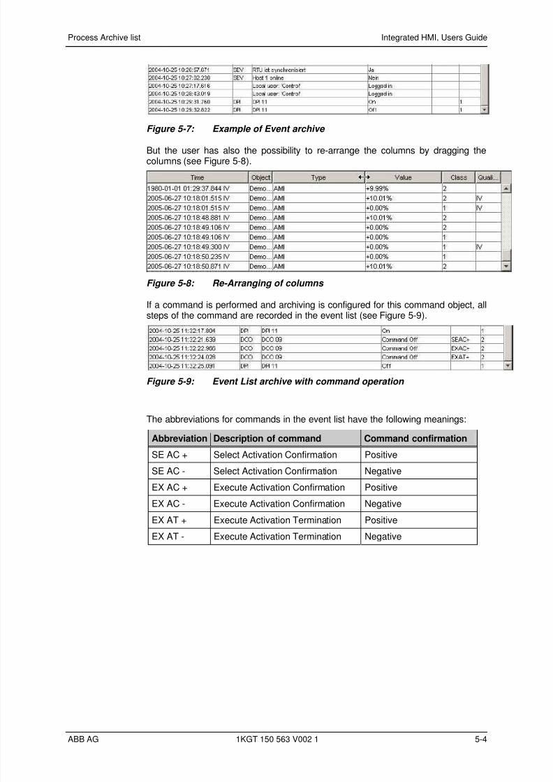
5.4 Representation of process archive entries
The initial representation of an archive is the same as in the HMI Editor (see Figure5-6 to Figure 5-7).
Figure 5-6: Example of Integrated Total and Measured Value Archive
ABB AG 1KGT 150 563 V002 1 5-3
7/29/2019 HMI User guide
http://slidepdf.com/reader/full/hmi-user-guide 30/34
Process Archive list Integrated HMI, Users Guide
Figure 5-7: Example of Event archive
But the user has also the possibility to re-arrange the columns by dragging thecolumns (see Figure 5-8).
Figure 5-8: Re-Arranging of columns
If a command is performed and archiving is configured for this command object, allsteps of the command are recorded in the event list (see Figure 5-9).
Figure 5-9: Event List archive with command operation
The abbreviations for commands in the event list have the following meanings:
Abbreviation Description of command Command confirmation
SE AC + Select Activation Confirmation Positive
SE AC - Select Activation Confirmation Negative
EX AC + Execute Activation Confirmation Positive
EX AC - Execute Activation Confirmation Negative
EX AT + Execute Activation Termination Positive
EX AT - Execute Activation Termination Negative
ABB AG 1KGT 150 563 V002 1 5-4
7/29/2019 HMI User guide
http://slidepdf.com/reader/full/hmi-user-guide 31/34
6 Alarm list
6.1 General The RTU560 Integrated HMI is supporting one Alarm List for
• Persistent alarms
• Fleeting unacknowledged alarms
It is a part of the data entry, to specify the value(s) which will generate an alarm.
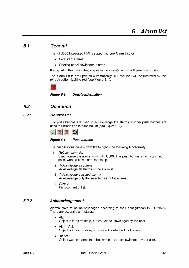
The alarm list is not updated automatically, but the user will be informed by therefresh button flashing red (see Figure 6-1).
Figure 6-1: Update information
6.2 Operation
6.2.1 Control Bar
Two push buttons are used to acknowledge the alarms. Further push buttons areused to refresh and to print the list (see Figure 6-1).
Figure 6-1: Push buttons
The push buttons have – from left to right - the following functionality:
1. Refresh alarm list Synchronize the alarm list with RTU560. This push button is flashing in redcolor, when a new alarm comes up.
2. Acknowledge all alarms Acknowledge all alarms of the alarm list.
3. Acknowledge selected alarms Acknowledge only the selected alarm list entries.
4. Print list
Print content of list.
6.2.2 Acknowledgement
Alarms have to be acknowledged according to their configuration in RTUtil560.There are several alarm status:
• AlarmObject is in alarm state, but not yet acknowledged by the user.
• Alarm-AckObject is in alarm state, but was acknowledged by the user.
• -no text-Object was in alarm state, but was not yet acknowledged by the user.
ABB AG 1KGT 150 563 V002 1 6-1
7/29/2019 HMI User guide
http://slidepdf.com/reader/full/hmi-user-guide 32/34
Alarm list Integrated HMI, Users Guide
A persistent alarm has to be acknowledged by the operator, if this feature wasenabled during data entry.
If an acknowledged alarm disappears, the entry will be deleted from the alarm list.
If an acknowledgement is not required, a fleeting alarm will be deleted from thealarm list.
If the acknowledgement is required, a fleeting alarm will stay in the alarm list, andhas to be acknowledged later.
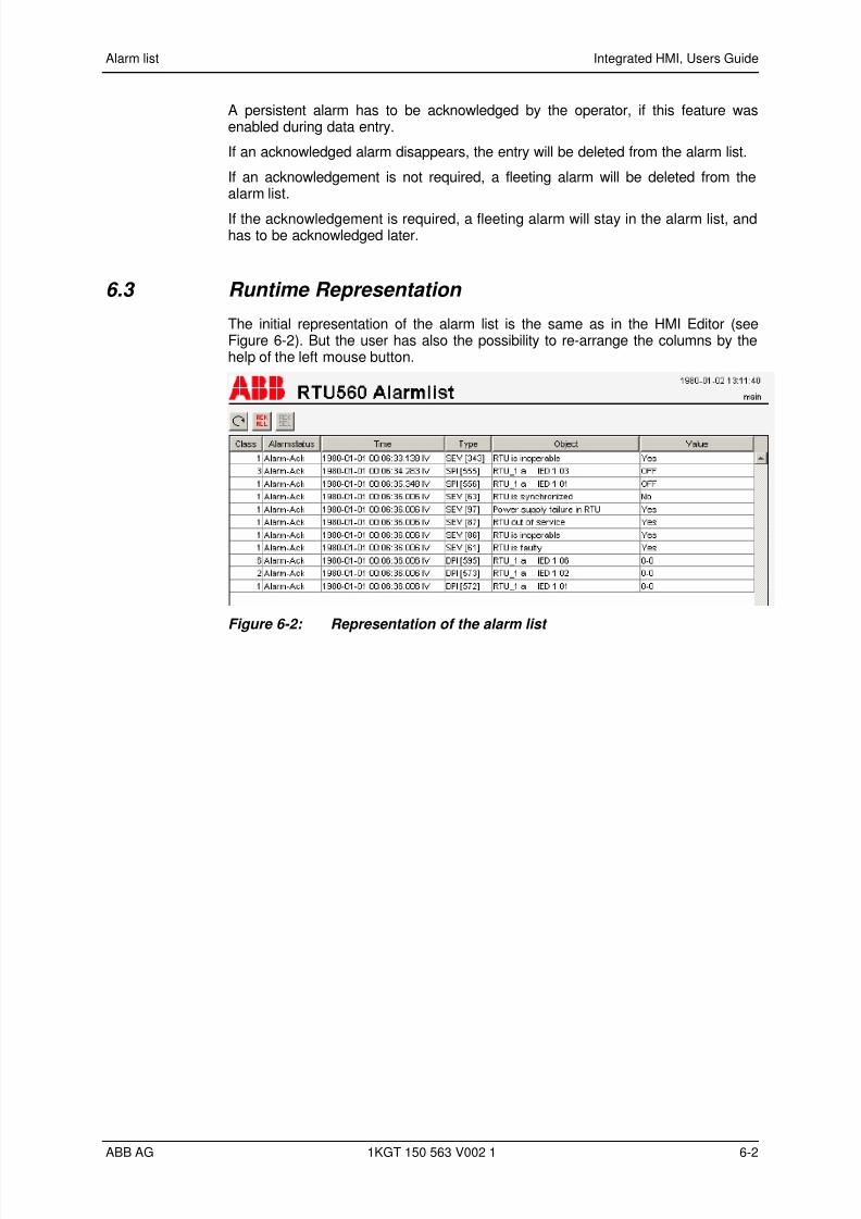
6.3 Runtime Representation
The initial representation of the alarm list is the same as in the HMI Editor (seeFigure 6-2). But the user has also the possibility to re-arrange the columns by thehelp of the left mouse button.
Figure 6-2: Representation of the alarm list
ABB AG 1KGT 150 563 V002 1 6-2

7/29/2019 HMI User guide
http://slidepdf.com/reader/full/hmi-user-guide 33/34

7/29/2019 HMI User guide
http://slidepdf.com/reader/full/hmi-user-guide 34/34
Integrated HMI, Users Guide
ABB AGPower Technologies DivisionPower Technology Systems
Kallstadter Str. 1, 68309 MannheimTelephone +49 (0) 621 381 – 0Fax +49 (0) 621 381 – 7622
www.abb.de/pt
Subject to alteration