Virtual HMI User Instructions
40
Virtual HMI User Instructions ISC CAM AIM Technology Version 1.0 23 April 2021
Transcript of Virtual HMI User Instructions

Virtual HMI User InstructionsISC CAM AIM Technology
Version 1.023 April 2021

Table of Contents• Intended Design and Use of the Virtual HMI• How to use this document?• Good to know• How to connect to the ISC CAM Virtual HMI? • HMI Overview• HMI Page
• Live Info• Settings• Maintenance• Machine• IO-Communication• Fauts
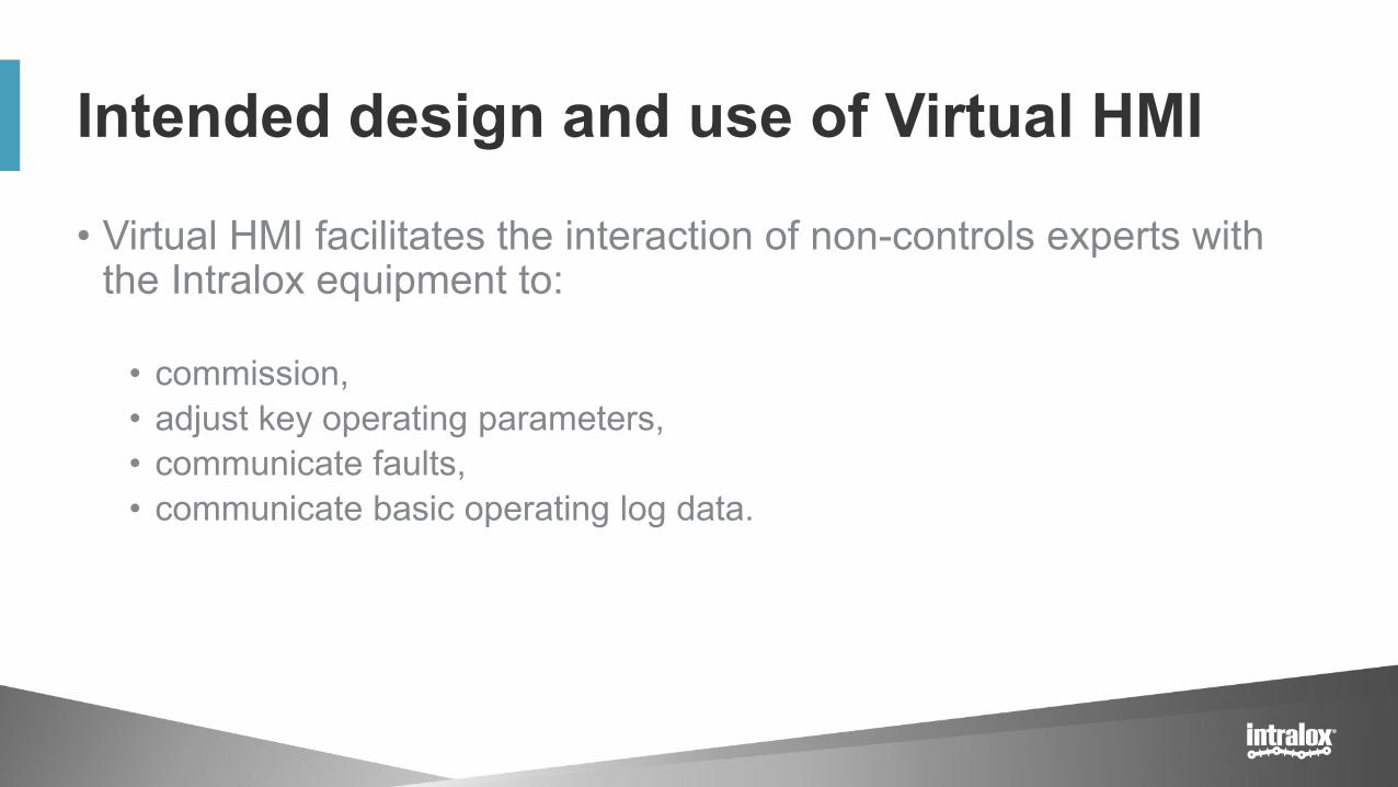
Intended design and use of Virtual HMI
• Virtual HMI facilitates the interaction of non-controls experts with the Intralox equipment to:
• commission,• adjust key operating parameters,• communicate faults,• communicate basic operating log data.

How to use this document• Additional documents from the Intralox User Manual
• Mechanical drawing of Intralox Equipment• Dimensions of Intralox equipment and position of the components
• Functional layout drawing of Intralox equipment• Application information: product trajectories, belt speeds, min product gaps,
• ISC Interlocks Document
• ISC Troubleshooting Guide

Good to know• Default IP Address:
192.168.1.254
• IP address displayed on the HMI updates only after reboot of the ISC CAM (power off/on).
• Click on “Submit” button to implement changes on the ‘fly’.
• Units: SI
• All parameters/values displayed on HMI are available on the ethernet network

Connection to the Virtual HMI

How to connect to the Virtual HMI?
• Connect with a laptop to the ethernet network of the ISC CAM• If the ISC CAM is not connected to any ethernet, connect directly to the
ethernet port of the ISC CAM.
• Write the IP address of the ISC CAM on the navigation bar of an internet browser such as Microsoft Edge, Google Chrome, Mozilla Firefox or similar.
• If the IP address of the ISC CAM is unknown, please request it to the responsible/manager of PLC network.
• Default IP address: 192.168.1.254

HMI Overview

Number of pages & high level Description
• The Virtual HMI has 6 different pages
1. Live: landing page2. Settings3. Maintenance4. Machine5. IO-Communication6. Faults

Interface Overview1. Navigation pannel
• Live Info• Settings• Maintenance• Machine• IO-COMM• Fault
2. Bottom Information Bar1. IP Address of ISC CAM2. MAC Address: electronic unique
identifier3. SW Version: Intalox Divert Logic
Version4. DPE Model: Intralox Product Family5. S/N: serial number of the Intralox
equipment
3. Page Unique Information
4. Live bit
1
2
34

Intralox Equipment
Infeed Divert area 1
Pneumatic Solenoid Valve(s)
Encoder
Infeed Product Sensor
Zero Position
Divert area 2
Pneumatic Solenoid Valve(s)ISC CAM
Divert Direction 1 Divert Direction 2
Divert Direction 0

1. Live page

End in Mind• Provide an overview of the status of Intralox equipment using real-time
operating data. The data is generated from the field components:• Infeed product sensor, • encoder,• solenoids valves
• ‘Read only’ page
• Intended users: Any user such as equipment operator, controlsengineers, maintenance tech

Live Info – Indicators• System
General status of the system to run
• BeltStatus of the belt.
• Infeed SensorStatus infeed Product Sensor.
• GapStatus of gap between 2 consecutive products measured by the infeed product sensor. See page faults for definition of GAP not “OK”.
Gap shorter than “Min Gap at Infeed” triggers fault signal to PLC. See troubleshooting guideline.

Live Info – Indicators • Throughput
Number of products crossing the infeed product sensor in the last minute, updated every minute (not instantaneously)
• Belt SpeedLinear belt speed.
• (Belt) Run TimeTime Duration since ISC CAM is powered on first time. It only increases when the belt is moving (receiving encoder pulses)
• Up TimeTime duration since the ISC CAM was last time powered on.
• Belt UsageTotal distance travelled by the belt since first encoder pulse.
• Gap FaultTotal number of ‘Gap Not OK’ since the first encoder pulse. See page faults for definition of GAP not “OK”.
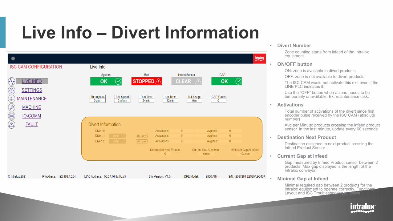
Live Info – Divert Information• Divert Number
Zone counting starts from infeed of the Intralox equipment
• ON/OFF buttonON: zone is available to divert productsOFF: zone is not available to divert productsThe ISC CAM would not activate this exit even if the LINE PLC indicates it.Use the “OFF” button when a zone needs to be temporarily unavailable. Ex: maintenance task.
• ActivationsTotal number of activations of the divert since first encoder pulse received by the ISC CAM (absolute number)Avg per Minute: products crossing the infeed product sensor in the last minute, update every 60 seconds
• Destination Next ProductDestination assigned to next product crossing the Infeed Product Sensor.
• Current Gap at InfeedGap measured by Infeed Product sensor between 2 products. Max gap displayed is the length of the Intralox conveyor.
• Minimal Gap at InfeedMinimal required gap between 2 products for the Intralox equipment to operate correctly. Functional Layout and ISC Troubleshooting guideline.

2. Settings Page

Setting: End in Mind
• Provides the ability to modify key operating parameters (settings) of the Intralox equipment to optimise the trajectory of products.
• ‘Read and Write’. Option to import and export ‘Application setting files’
• Intended users• Technical operators looking for adjusting the performance of the Intralox
equipment. Ex. maintenance tech

Setting General• Import Setting Button
Import to the ISC CAM backup application setting files to (extension “.apl”). Ex: factory setting
• Export Data ButtonExport application setting files to generate backup
• Internal Count 0, 1 and 2Slugs/Train functionality. Number of products allocated to divert #. Only applicable when ISC CAM is working in “Internal Model”, see HMI Page “Machine”.
• Min Product LengthMinimum product length configured for this Intralox equipment. See Functional Layout
• PE Position OffSetInfeed Product Sensor distance from the Zero Position. See Mechanical Drawing.
• Default DestinationDestination of product when no signal is received from the Line PLC (external mode) or no slugs/train function is set (internal mode)
Click “Submit” button to implement
changes

Setting General• Divert OffSet
(Start of ) divert area distance from the position defined by Intralox. See Mechanical Drawing of position.
• Activation Delay OverrideThis value considers mechanical delays of the activation system of the Intralox equipment from product detection until product starts moving on the belt.
• SUBMIT BUTTONClick button for making the modifications on the ISC CAM firmware effective.
Click “Submit” button to implement
changes

3. Maintenance Page

End in Mind
• Display the ‘equipment log’ with absolute counter values
• ‘Read only’, ability to export counter files.
• Intended users: maintenance.

Maintenance• Up time
Time elapsed since the ISC CAM was powered on. It resets to zero when the ISC CAM is powered off.
• Belt Run TimeTime elapsed since the ISC CAM received the first encoder pulse. It only increments when the ISC CAM receives encoder pluses. It never resets to zero
• Belt UsageTotal distance travelled by the belt since first encoder pulse. It never resets to zero
• Product CountTotal count number of products that passed the infeed product sensor (absolute value) since first encoder pulse.
• GAP Fault CountTotal number of ‘Gap Not OK’ since the first encoder pulse. See page faults for definition of GAP not “OK”.
• Divert 0, 1, 2 Total number of activations of each divert since first encoder pulse .
• Save Counters BUTTONClick button to export the counter values. File extension is ‘cnt’ and requires Intralox tool to make it readable.

4. Machine Page

End in Mind• Ability to modify key operating parameters (settings) of the Intralox
equipment to optimise the trajectory of products.
• ‘Read and write’• Read: read the Intralox equipment mechanical dimensions relevant for the
automation of the carryway• Write: upload files with the mechanical dimensions of the Intralox equipment
• Intended users• Controls engineers integrating the ISC CAM into the Line network
(communication)• Maitenance operators troubleshooting
• See Functional Layout and Mechanical Drawing

Machine -Application Data• Application
Type of functionality that the Intralox equipment is performing when diverting products: Sorter or Switch
• Activation TypeType of mechanical activation mechanism used for engaging with Intralox belt for diverting products: PopUp, RnR or AIM
• Belt TypeIntralox Belt series used in the Intralox equipment.
• Minimum GapMinimum distance between products at the infeed of Intralox See Functional Layout
• Hardware SignalSelections: enable or disable. Hardwire signal “enable” results that ONLY the 1st divert reacts to the discrete signal of 24VDC to activate. The discrete signal has priority over the ethernet signal. Use hardware signal when the Intralox equipment has a high-speed reject
• Run ModeSelections: Internal or externalInternal Mode: ISC CAM operates in autonomous mode with an internal counter for diverting productsExternal Mode: ISC CAM requires the input signal from the Line PLC for diverting (or not) each product.
• Sensor Mode Selection: Light On / Dark OnApplicable to infeed product sensor. Use only for replacement
• Fault OverrideSelection: number, overrides faults. See HMI Page “Faults”.
Click “Submit” button to implement
changes

Machine –Belt Data• Conveyor Length
Length in [mm] of the frame of the Intralox equipment.
• Width Belt width
• Sprocket TeethNumber of teeth of the sprocket
• PitchLength of the module of the belt.
• Encoder ResolutionNumber of pulses generated by the encoder per revolution. Standard = 64 pulse/rev
• Belt Travel/pulseConversion of the belt travel distance in [1/10mm] for each encoder pulse. Dependant of the belt pitch
• Maximum SpeedRecommended Maximum belt speed of the Intralox equipment. Functional Layout.
• Minimum SpeedRecommended minimum belt speed of Intralox equipment. Functional Layout
Click “Submit” button to implement
changes

Machine – Divert Data• Divert Area Count
Area # starts from infeed of the Intralox equipment. See image in next page.
• Zone LengthLength of the divert zone
• Inf Sensor CountNumber of Infeed product sensor.
• PE PositionInfeed Product Sensor distance from the Zero Position.
Click “Submit” button to implement
changes

Machine - Area• Position
(Start of) divert area distance from the Zero Position.
• Activation DelayStandard mechanical activation delay between a signal is received by the ISC CAM and the product starts moving on the belt.
• Peg Sensor OffSetPeg sensor distance from Zero Position
• SUBMIT BUTTONPush button for making the modifications in the ISC CAM firmware effective.
• NOTE: Area 2 is optionalClick “Submit”
button to implement changes

AIM Technology

5.IO-COMM Page

End in Mind
• Detail the communication status between the ISC CAM with the field components and the line PLC. Please refer to the ISC CAM Interlocks Document for additional information and ISC Troubleshooting document actions
• ‘read only’
• Intended users• Line control engineers

IO-COMM Status• Encoder
Status of encoder, blinking with each pulse
• Infeed PEStatus of infeed product sensor
• Reject SignalStatus of hardwire reject signal
• Peg Sensor 1Only applicable for AIM applications. Status of peg sensor of divert 1, blinking with each peg passing the beam the peg sensor (belt has to move)
• Peg Sensor 2Only applicable for AIM applications. Status of peg sensor of divert 2, blinking with each peg passing the beam the peg sensor (belt has to move)

IO-COMM Status• IO-Link Output Status
Out Port 1 valveOnly applicable to RnR technology. Status of valve bank.
Out Port 2 valve (optional)Only applicable to RnR technology. Status of valve bank.
• Hardware Output StatusValve 1Only applicable to Popup and AIM technologyOFF: valve is offON: valve is on.
Valve 2 (optional)Only applicable to Popup and AIM technologyOFF: valve is offON: valve is on.

IO-COMM Input Words1. Words sent by the ISC CAM to the
Line PLC through the ethernet network
2. See ISC CAM Interlocks file for details

IO-COMM Output Words1. Words received by the ISC CAM from
the Line PLC through the ethernet network
2. See ISC CAM Interlocks file for details

6. Fault Page
End in Mind• Display the status of the faults generated by the ISC CAM in
human readable interface.
• Refer to the ISC CAM Interlocks Document for details and ISC Troubleshooting document for actions
• ‘Read only’
• Intended users: all users

Fault 0-7 • Fault Code 0No encoder signal received from encoder
• Fault Code 1Encoder pulsing but no signal received from Line PLC for motor on.
• Fault Code 2Belt speed is slower than minimum recommended speed. See Functional Layout for minimum speed.
• Fault Code 3Belt speed is faster than maximum recommended speed. See Functional Layout for maximum speed
• Fault Code 4Infeed Product sensor blocked , see ISC troubleshooting guide.
• Fault Code 5Optional. See Functional Layout for configuration of Intralox Equipment
• Fault Code 6Optional. See Functional Layout for configuration of Intralox Equipment
• Fault Code 7Only applicable to AIM technology. Peg sensor blocked 1 or 2 (if applicable), see ISC troubleshooting guide.

Fault 8-15 • Fault Code 8Only applicable to AIM TechnologyPeg missing in the belt.
• Fault Code 9See Functional Layout for min gap value
• Fault Code 10Power supply low voltage. See ISC troubleshooting guide.
• Fault Code 11Current draw too high. , see ISC troubleshooting guide.
• Fault Code 12Only applicable to RnR TechnologyOptional. See Functional Layout for configuration of Intralox equipment
• Fault Code 13Only applicable to RnR TechnologySee Functional Layout for configuration of Intralox equipment and ISC troubleshooting guide.
• Fault Code 14Only applicable to RnR TechnologyOptional. See Functional Layout for configuration of Intralox equipment , and ISC troubleshooting guide.
• Fault Code 15Only applicable to RnR TechnologyOptional. See Functional Layout for configuration of Intralox equipment and ISC troubleshooting guide.