Appendix D Scenario Outline Form ES-D-1
79
Appendix D Scenario Outline Form ES-D-1 NUREG-1021, R9 Supp. 1 Page 1 of 16 FENOC Facsimile AG Facility: Davis-Besse Scenario No.: 1 Op Test No.: DB NRC 2015 Examiners: Operators: SRO ATC BOP Initial Conditions: 100% Power CCW Pump 1 and MUP 2 in service Turnover: Maintain 100% Power Critical tasks: 1. ATWS (CT24) 2. Establish FW flow and feed SGs (CT10) Event No. Malf. No. Event Type* Event Description 1 SRO (TS) AFPT 1 Trip valve fails closed 2 C-BOP/SRO Circ Pump high stator temperature 3 I-ATC/SRO Pressurizer Level instrument failure 4 C-BOP/SRO Rising Condenser pressure 5 C-ATC/SRO (TS) Makeup Pump trip 6 R-ATC/SRO Loss of Letdown 7 C-ATC/SRO ATWS (trip pushbuttons fail) 8 M-All SG 1 stuck open safety 9 C-BOP/SRO AFPT 2 to SG 2 overfeed 10 C-ATC/SRO Spray valve fails open * (N)ormal, (R)eactivity, (I)nstrument, (C)omponent, (M)ajor
Transcript of Appendix D Scenario Outline Form ES-D-1

Appendix D Scenario Outline Form ES-D-1
NUREG-1021, R9 Supp. 1 Page 1 of 16 FENOC Facsimile AG
Facility: Davis-Besse Scenario No.: 1 Op Test No.: DB NRC 2015
Examiners: Operators: SRO
ATC
BOP
Initial Conditions: 100% Power
CCW Pump 1 and MUP 2 in service
Turnover: Maintain 100% Power
Critical tasks: 1. ATWS (CT24)
2. Establish FW flow and feed SGs (CT10)
Event No.
Malf. No.
Event Type* Event Description
1 SRO (TS) AFPT 1 Trip valve fails closed
2 C-BOP/SRO Circ Pump high stator temperature
3 I-ATC/SRO Pressurizer Level instrument failure
4 C-BOP/SRO Rising Condenser pressure
5 C-ATC/SRO (TS) Makeup Pump trip
6 R-ATC/SRO Loss of Letdown
7 C-ATC/SRO ATWS (trip pushbuttons fail)
8 M-All SG 1 stuck open safety
9 C-BOP/SRO AFPT 2 to SG 2 overfeed
10 C-ATC/SRO Spray valve fails open
* (N)ormal, (R)eactivity, (I)nstrument, (C)omponent, (M)ajor

Scenario Event Summary
NUREG-1021, R9 Supp. 1 Page 2 of 16 FENOC Facsimile AG
DAVIS-BESSE 2015 NRC SCENARIO 1 The Crew will take the watch with power at 100%. Following turnover the Lead Evaluator will cue the Auxiliary Feed Pump (AFP 1) Turbine Trip Throttle Valve (TTV) to fail closed and annunciator alarm, AFP1 TRBL, will come into alarm. The SRO will declare AFP 1 Inoperable and enter the applicable Tech Spec (TS). After the AFP TS is entered, the Lead Evaluator can cue the Circulating Water Pump (CWP) stator temperature increase. The SRO will implement DB-OP-02517, Circulating Water System Malfunctions. The BOP will be directed to stop CWP 1 When CWP 1 is stopped the lead evaluator will cue the selected PZR Level instrument failure which will fail low over two minutes. Annunciator PZR LVL LO will alarm. The SRO will implement DB-OP-02513, PZR Abnormal Operations. The ATC will place PZR level control valve MU32 in manual, select the alternate instrument and return MU32 to automatic control. After MU32 is returned to automatic control the Lead Evaluator will cue the rising condenser pressure. The SRO will implement DB-OP-02518, HIGH CONDENSER PRESSURE. The BOP will recognize the Mechanical Hogger (motor vacuum pump) has failed to auto start. The BOP will start the Mechanical Hogger and the pressure increase will stop. The Lead Evaluator will then cue the Makeup Pump trip. The SRO will implement DB-OP-02512, Loss of RCS Makeup. The ATC will close MU2B, RCS Letdown, MU19 Seal injection and MU32 PZR level control. The SRO will enter the applicable TS for the Inoperable Makeup Pump. The ATC will start the standby Makeup pump and restore MU flow, Seal Injection flow and attempt to restore Letdown flow. The Letdown valve, MU2B, will be failed closed. The SRO will implement DB-OP-02512, for Loss of Letdown Flowpath. When it is determined Letdown flow cannot be established the SRO will direct a plant shutdown per DB-OP-02504, Rapid Shutdown. While the shutdown is in progress the Lead Evaluator can cue the CD2796 close failure which causes a loss of condensate flow. The Deaerator levels will drop causing a runback and as the Deaerator levels approach off scale low the SRO will direct tripping the Reactor, tripping both MFPTs and Steam Feed Rupture Control System (SFRCS) initiation and isolation per the Deaerator level alarm procedure DB-OP-02013, Alarm Panel 13 annunciators. The ATC will attempt to trip the Reactor per DB-OP-02000. The trip buttons will not function and the ATC will de-energize E2 and F2 (CRD) to trip the Reactor (CT-24). The ATC will trip both MFPT and initiate and isolate SFRCS (CT-10). SG1 safety will stick open. DB-OP-02000, Overcooling Section 7, will be entered. The Motor Driven Feed Pump will fail to start. AFPT 2 will start and feed at full flow with its discharge failed open. The BOP will be required to control SG2 level with AFPT 2 speed control (CT-10). The BOP will control RCS temperature using SG2 AVV and the ATC will begin depressurizing the Reactor Coolant System to minimum subcooling margin. When the RCS spray valve is opened it will fail and the ATC will close the spray block. When the spray valve is isolated and SG2 level is controlled the scenario can be terminated.

Appendix D Operator Action Form ES-D-2 Op Test No.: 2015 Scenario # 1 Event # 1 Page 3 of 16 Event Description: AFPT 1 Trip Throttle Valve (TTV) fails closed
Time Position Applicant’s Actions or Behavior
NUREG-1021, R9 Supp. 1 Page 3 of 16 FENOC Facsimile AG
Event 1: AFPT 1 TTV Fails Closed Indications Available: 10-4-G, AFP 1 TRBL 10-2-G, AFPT 1 OVRSPD TRIP Computer Alarm Z001, AFPT 1 STOP/GOV/STM IN ISO VLVS
CREW Recognize AFP 1 TRBL Annunciator Alarm
BOP Implement DB-OP-02010, Feedwater Alarm Panel 10 Annunciators alarm 10-4-G, AFP 1 TRBL
CREW Diagnose AFPT 1 Trip Throttle Valve not fully open by computer alarm Z001
BOP Dispatch Equipment Operator to inspect AFPT 1
Booth Cue
After 2 minutes role play as Equipment Operator and report: “AFPT 1 Trip Throttle Valve is tripped closed”
SRO Direct opening AFPT 1 Trip Throttle Valve. Request Maintenance assistance.
Booth Cue
Role play as Equipment Operator and report: “AFPT 1 Trip Throttle Valve will not reset and Maintenance requests it be tagged out for troubleshooting”
SRO Declare AFPT 1 Inoperable. Enter TS 3.7.5, Condition B
• Direct energize blue TS Operability light
SRO Request Risk evaluation or refer to Risk Matrix and determine risk level is Yellow (OPTIONAL)
On Lead Evaluator’s discretion, insert Event 2, Circulating Water Pump high temp
Appendix D Operator Action Form ES-D-2 Op Test No.: 2015 Scenario # 1 Event # 2 Page 4 of 16 Event Description: Circulating Water Pump 1 high stator temperature
Time Position Applicant’s Actions or Behavior
NUREG-1021, R9 Supp. 1 Page 4 of 16 FENOC Facsimile AG
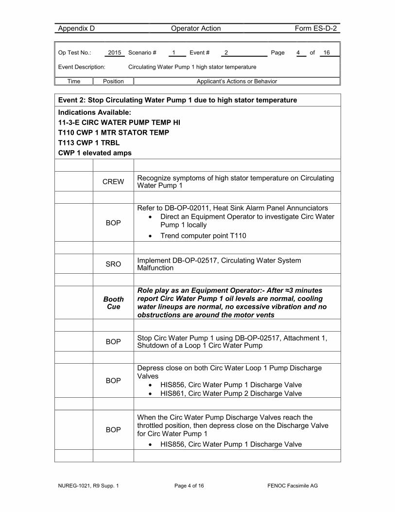
Event 2: Stop Circulating Water Pump 1 due to high stator temperature Indications Available: 11-3-E CIRC WATER PUMP TEMP HI T110 CWP 1 MTR STATOR TEMP T113 CWP 1 TRBL CWP 1 elevated amps
CREW Recognize symptoms of high stator temperature on Circulating Water Pump 1
BOP
Refer to DB-OP-02011, Heat Sink Alarm Panel Annunciators • Direct an Equipment Operator to investigate Circ Water
Pump 1 locally • Trend computer point T110
SRO Implement DB-OP-02517, Circulating Water System Malfunction
Booth Cue
Role play as an Equipment Operator:- After ≈3 minutes report Circ Water Pump 1 oil levels are normal, cooling water lineups are normal, no excessive vibration and no obstructions are around the motor vents
BOP Stop Circ Water Pump 1 using DB-OP-02517, Attachment 1, Shutdown of a Loop 1 Circ Water Pump
BOP
Depress close on both Circ Water Loop 1 Pump Discharge Valves
• HIS856, Circ Water Pump 1 Discharge Valve • HIS861, Circ Water Pump 2 Discharge Valve
BOP
When the Circ Water Pump Discharge Valves reach the throttled position, then depress close on the Discharge Valve for Circ Water Pump 1
• HIS856, Circ Water Pump 1 Discharge Valve
Appendix D Operator Action Form ES-D-2 Op Test No.: 2015 Scenario # 1 Event # 2 Page 5 of 16 Event Description: Circulating Water Pump 1 high stator temperature
Time Position Applicant’s Actions or Behavior
NUREG-1021, R9 Supp. 1 Page 5 of 16 FENOC Facsimile AG
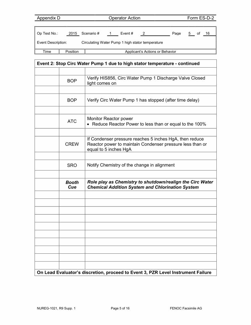
Event 2: Stop Circ Water Pump 1 due to high stator temperature - continued
BOP Verify HIS856, Circ Water Pump 1 Discharge Valve Closed light comes on
BOP Verify Circ Water Pump 1 has stopped (after time delay)
ATC Monitor Reactor power • Reduce Reactor Power to less than or equal to the 100%
CREW If Condenser pressure reaches 5 inches HgA, then reduce Reactor power to maintain Condenser pressure less than or equal to 5 inches HgA
SRO Notify Chemistry of the change in alignment
Booth Cue
Role play as Chemistry to shutdown/realign the Circ Water Chemical Addition System and Chlorination System
On Lead Evaluator’s discretion, proceed to Event 3, PZR Level Instrument Failure
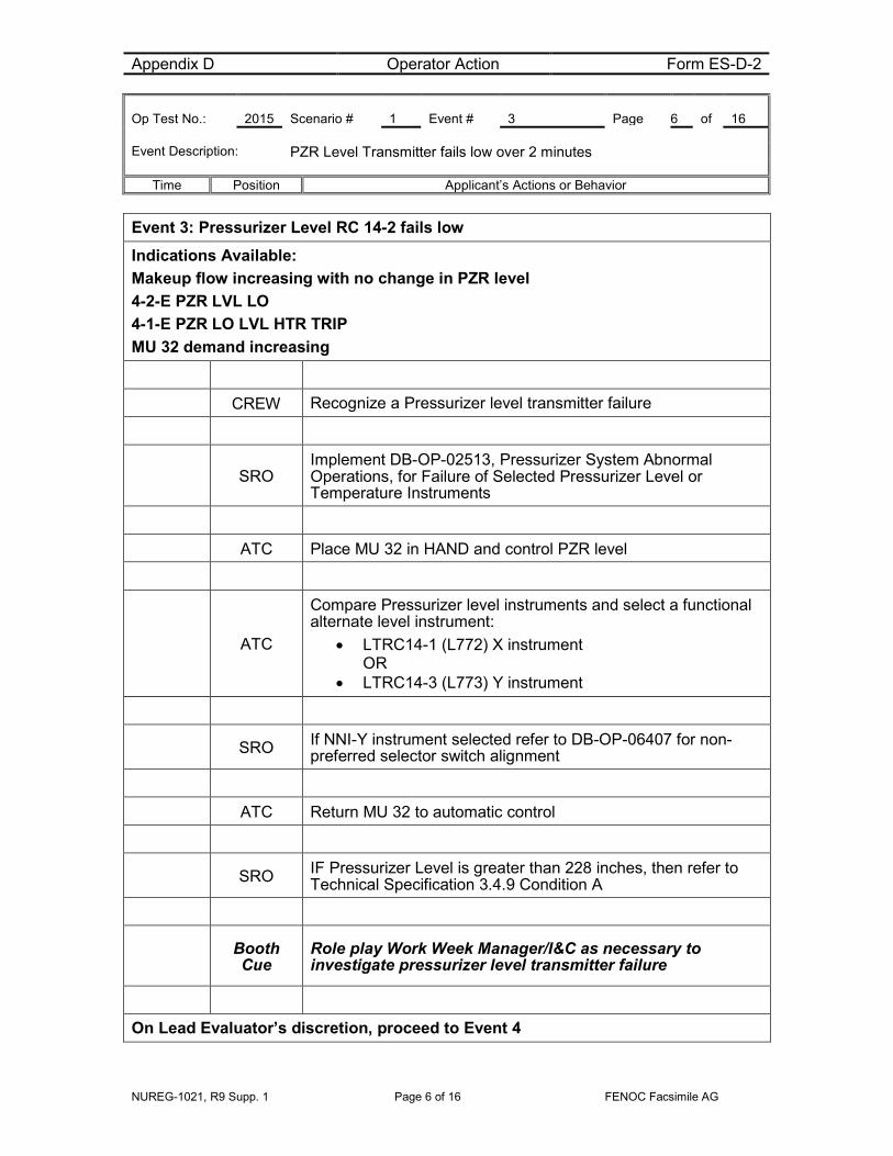
Appendix D Operator Action Form ES-D-2 Op Test No.: 2015 Scenario # 1 Event # 3 Page 6 of 16 Event Description: PZR Level Transmitter fails low over 2 minutes
Time Position Applicant’s Actions or Behavior
NUREG-1021, R9 Supp. 1 Page 6 of 16 FENOC Facsimile AG
Event 3: Pressurizer Level RC 14-2 fails low Indications Available: Makeup flow increasing with no change in PZR level 4-2-E PZR LVL LO 4-1-E PZR LO LVL HTR TRIP MU 32 demand increasing
CREW Recognize a Pressurizer level transmitter failure
SRO
Implement DB-OP-02513, Pressurizer System Abnormal Operations, for Failure of Selected Pressurizer Level or Temperature Instruments
ATC Place MU 32 in HAND and control PZR level
ATC
Compare Pressurizer level instruments and select a functional alternate level instrument:
• LTRC14-1 (L772) X instrument OR
• LTRC14-3 (L773) Y instrument
SRO If NNI-Y instrument selected refer to DB-OP-06407 for non-preferred selector switch alignment
ATC Return MU 32 to automatic control
SRO IF Pressurizer Level is greater than 228 inches, then refer to Technical Specification 3.4.9 Condition A
Booth Cue
Role play Work Week Manager/I&C as necessary to investigate pressurizer level transmitter failure
On Lead Evaluator’s discretion, proceed to Event 4

Appendix D Operator Action Form ES-D-2 Op Test No.: 2015 Scenario # 1 Event # 4 Page 7 of 16 Event Description: Rising Condenser Pressure – vacuum pump auto start failure
Time Position Applicant’s Actions or Behavior
NUREG-1021, R9 Supp. 1 Page 7 of 16 FENOC Facsimile AG
Event 4: Rising Condenser pressure Indications Available: 15-1-F HP CNDSR PRESS HI 15-2-F LP CNDSR PRESS HI 15-5-B DEHC MINOR ALARM
CREW Recognize rising Condenser pressure
BOP
NOTE: Crew may take actions prior to alarm Implement DB-OP-02015, TURBINE ALARM PANEL 15 ANNUNCIATORS (alarm comes in at 5.7 inches HgA)
• Check pressure at PR530 • Check pressure at PR541
SRO Implement DB-OP-02518, HIGH CONDENSER PRESSURE
ATC Monitor Reactor Power • Maintain Reactor Power 100% or less
BOP IF AT ANY TIME Condenser Pressure reaches 4.5 inches HgA (LP Condenser), THEN verify the Mechanical Hogger Starts
ATC IF AT ANY TIME Condenser Pressure reaches 5 inches HgA THEN reduce Reactor Power to maintain Condenser pressure less than or equal to 5 inches HgA
BOP Recognize Condenser Pressure reaches 4.5 inches HgA (LP Condenser) and Mechanical Hogger has not started
BOP Start Mechanical Hogger
• HIS1005 Mechanical Hogger
CREW Recognize condenser pressure rise has stopped
On Lead Evaluator’s discretion, when Condenser pressure rise has been stopped, proceed to Event 5, Loss of RCS Makeup
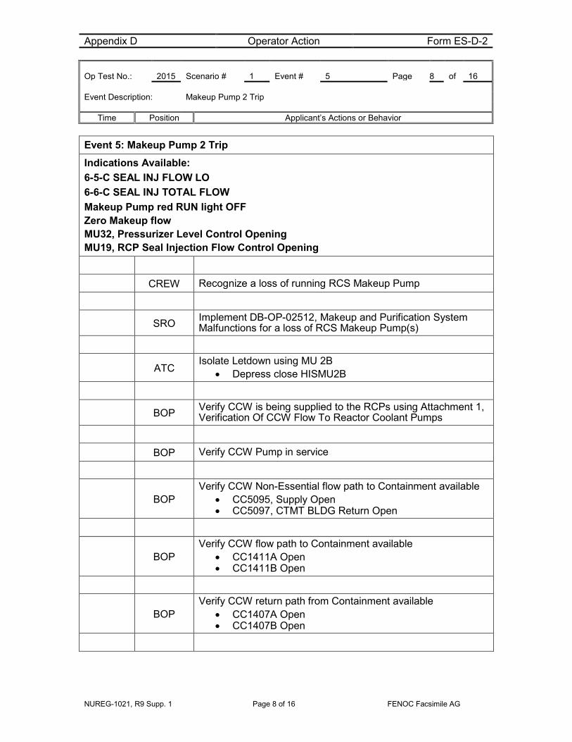
Appendix D Operator Action Form ES-D-2 Op Test No.: 2015 Scenario # 1 Event # 5 Page 8 of 16 Event Description: Makeup Pump 2 Trip
Time Position Applicant’s Actions or Behavior
NUREG-1021, R9 Supp. 1 Page 8 of 16 FENOC Facsimile AG
Event 5: Makeup Pump 2 Trip Indications Available: 6-5-C SEAL INJ FLOW LO 6-6-C SEAL INJ TOTAL FLOW Makeup Pump red RUN light OFF Zero Makeup flow MU32, Pressurizer Level Control Opening MU19, RCP Seal Injection Flow Control Opening
CREW Recognize a loss of running RCS Makeup Pump
SRO Implement DB-OP-02512, Makeup and Purification System Malfunctions for a loss of RCS Makeup Pump(s)
ATC Isolate Letdown using MU 2B
• Depress close HISMU2B
BOP Verify CCW is being supplied to the RCPs using Attachment 1, Verification Of CCW Flow To Reactor Coolant Pumps
BOP Verify CCW Pump in service
BOP
Verify CCW Non-Essential flow path to Containment available • CC5095, Supply Open • CC5097, CTMT BLDG Return Open
BOP
Verify CCW flow path to Containment available • CC1411A Open • CC1411B Open
BOP
Verify CCW return path from Containment available • CC1407A Open • CC1407B Open

Appendix D Operator Action Form ES-D-2 Op Test No.: 2015 Scenario # 1 Event # 5 Page 9 of 16 Event Description: Makeup Pump 2 Trip
Time Position Applicant’s Actions or Behavior
NUREG-1021, R9 Supp. 1 Page 9 of 16 FENOC Facsimile AG
Event 5: Makeup Pump 2 Trip - continued
BOP
Verify Seal Cooling CCW Return flow path is available • RCP 1-1 CC4100 Open • RCP 1-2 CC4200 Open • RCP 2-1 CC4300 Open • RCP 2-2 CC4400 Open
BOP • Check Annunciator Alarm 6-5-B, SEAL CCW FLOW LOW is extinguished
BOP Notify SRO CCW flow is available to the Reactor Coolant pumps
ATC
Monitor Pressurizer level and compare to curve CC 4.3 Anytime Pressurizer Level is less than 160 inches, trip the reactor and go to DB-OP-02000
ATC Isolate RCP Seal Injection by closing MU19
ATC Place MU32 in Hand AND close MU32 to isolate the normal Makeup flowpath
SRO Refer to DB-OP-02515, Reactor Coolant Pump and Motor Abnormal Operation
CREW Monitor RCP Seal parameters
BOP/ATC Maintain Tave constant
SRO
Refer to TRM 8.1.1, Boration Systems – Operating Enter TRM 8.1.1, Nonconformance A
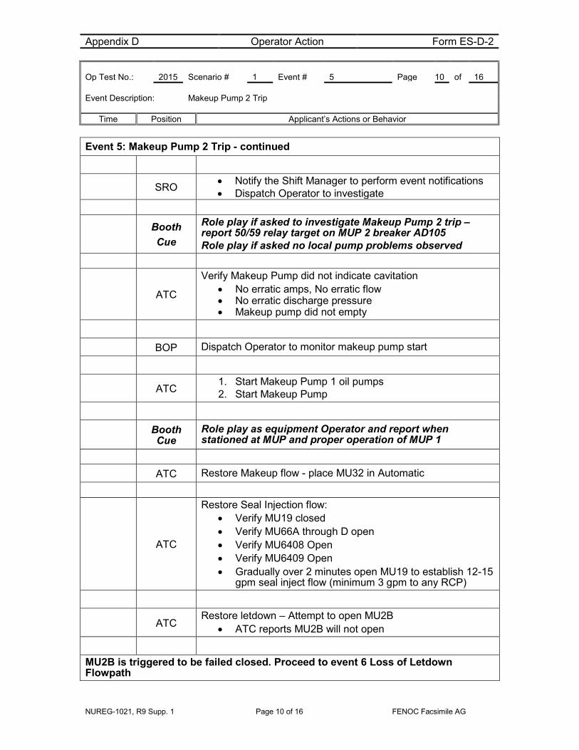
Appendix D Operator Action Form ES-D-2 Op Test No.: 2015 Scenario # 1 Event # 5 Page 10 of 16 Event Description: Makeup Pump 2 Trip
Time Position Applicant’s Actions or Behavior
NUREG-1021, R9 Supp. 1 Page 10 of 16 FENOC Facsimile AG
Event 5: Makeup Pump 2 Trip - continued
SRO • Notify the Shift Manager to perform event notifications • Dispatch Operator to investigate
Booth Cue
Role play if asked to investigate Makeup Pump 2 trip – report 50/59 relay target on MUP 2 breaker AD105 Role play if asked no local pump problems observed
ATC
Verify Makeup Pump did not indicate cavitation • No erratic amps, No erratic flow • No erratic discharge pressure • Makeup pump did not empty
BOP Dispatch Operator to monitor makeup pump start
ATC 1. Start Makeup Pump 1 oil pumps 2. Start Makeup Pump
Booth Cue
Role play as equipment Operator and report when stationed at MUP and proper operation of MUP 1
ATC Restore Makeup flow - place MU32 in Automatic
ATC
Restore Seal Injection flow: • Verify MU19 closed • Verify MU66A through D open • Verify MU6408 Open • Verify MU6409 Open • Gradually over 2 minutes open MU19 to establish 12-15
gpm seal inject flow (minimum 3 gpm to any RCP)
ATC Restore letdown – Attempt to open MU2B
• ATC reports MU2B will not open
MU2B is triggered to be failed closed. Proceed to event 6 Loss of Letdown Flowpath
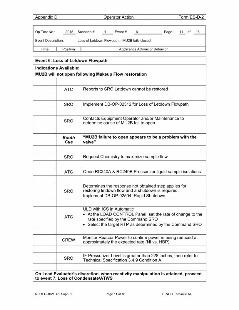
Appendix D Operator Action Form ES-D-2 Op Test No.: 2015 Scenario # 1 Event # 6 Page 11 of 16 Event Description: Loss of Letdown Flowpath – MU2B fails closed
Time Position Applicant’s Actions or Behavior
NUREG-1021, R9 Supp. 1 Page 11 of 16 FENOC Facsimile AG
Event 6: Loss of Letdown Flowpath
Indications Available: MU2B will not open following Makeup Flow restoration
ATC Reports to SRO Letdown cannot be restored
SRO Implement DB-OP-02512 for Loss of Letdown Flowpath
SRO Contacts Equipment Operator and/or Maintenance to determine cause of MU2B fail to open
Booth Cue
“MU2B failure to open appears to be a problem with the valve”
SRO Request Chemistry to maximize sample flow
ATC Open RC240A & RC240B Pressurizer liquid sample isolations
SRO Determines the response not obtained step applies for restoring letdown flow and a shutdown is required. Implement DB-OP-02504, Rapid Shutdown
ATC
ULD with ICS in Automatic • At the LOAD CONTROL Panel, set the rate of change to the
rate specified by the Command SRO • Select the target RTP as determined by the Command SRO
CREW Monitor Reactor Power to confirm power is being reduced at approximately the expected rate (NI vs. HBP)
SRO IF Pressurizer Level is greater than 228 inches, then refer to Technical Specification 3.4.9 Condition A
On Lead Evaluator’s discretion, when reactivity manipulation is attained, proceed to event 7, Loss of Condensate/ATWS

Appendix D Operator Action Form ES-D-2 Op Test No.: 2015 Scenario # 1 Event # 7 Page 12 of 16 Event Description: Loss of Condensate flow and ATWS
Time Position Applicant’s Actions or Behavior
NUREG-1021, R9 Supp. 1 Page 12 of 16 FENOC Facsimile AG
Loss of Condensate/ATWS Indications Available: 13-2-B CNDS PMP DISCH HDR PRESS FI578 COND PMP COMBINED FLOW indicates 0 MMPH
CREW Recognize Condensate flow is lost
BOP Implement DB-OP-02013 for 13-2-B
BOP Dispatch an Operator to investigate CD2796
Booth Cue
Role play as Equipment Operator and report CD2796 is closed and will not open
BOP Implement DB-OP-02013 for low Deaerator level
CREW Monitor proper runback when Deaerator levels reach 4 feet
SRO
When Deaerator levels approach off scale low direct: • Trip Reactor • Trip both MFPTs • Initiate and isolate SFRCS
*Critical Task ATC
Perform DB-OP-02000 immediate actions • Attempt to manually trip reactor • Report failure of manual pushbuttons to trip reactor • *De-energize E2 and F2 • Re-energize E2 and F2 • Verify power decreasing on the Intermediate Range • Manually trip the turbine • *Manually actuate SFRCS
Proceed to Events 8, 9 & 10

Appendix D Operator Action Form ES-D-2 Op Test No.: 2015 Scenario # 1 Event # 8, 9 & 10 Page 13 of 16 Event Description: SG1 Safety sticks open, SG2 overfill and PZR Spray fails open
Time Position Applicant’s Actions or Behavior
NUREG-1021, R9 Supp. 1 Page 13 of 16 FENOC Facsimile AG
Events 8, 9 & 10: SG1 Safety sticks open, SG2 overfill and PZR Spray fails open Indications Available: SG1 Pressure lowering SG2 Level rising above setpoint RC2, PZR Spray valve not closing
BOP Recognize no AFW flow to SG 1
BOP
Specific Rule 4 - Steam Generator Control - Refer to Attachment 5 to place the MDFP in service to feed SG 1 • Enable both MDFP Discharge Valves • Close both MDFP Discharge Valves • Attempt to start the MDFP • Recognize MDFP does not start
Booth Cue
If asked, role play as Equipment Operator and report MDFP breaker AD210 has overcurrent relay tripped
CREW Recognize overcooling SG1
SRO Implement DB-OP-02000, section 7 Overcooling
ATC
Implement Attachment 8, Place MU/HPI/LPI in Service • Start/Verify running both CCW Pumps • Start/Verify running both HPI Pumps • Verify open HP 2A, HP 2B, HP 2C and HP 2D • Start both LPI Pumps • Open DH 64 and DH 63 • Transfer Makeup Pump suctions, MU6405 & MU3971, to the
BWST • Set Pressurizer Level Controller to 100 inches • Lock MU Pump suctions, MU6405 & MU3971, on the BWST • Verify Pressurizer heaters are off
BOP Verify proper SFRCS. Refer to DB-OP-02000, Table 1 Events 8, 9 & 10: SG1 Safety sticks open, SG2 overfill and PZR Spray fails open

Appendix D Operator Action Form ES-D-2 Op Test No.: 2015 Scenario # 1 Event # 8, 9 & 10 Page 14 of 16 Event Description: SG1 Safety sticks open, SG2 overfill and PZR Spray fails open
Time Position Applicant’s Actions or Behavior
NUREG-1021, R9 Supp. 1 Page 14 of 16 FENOC Facsimile AG
CREW Diagnose stuck open safety SG1
BOP Control SG2 AVV to maintain RCS temperature constant or slowly lowering
BOP Recognize SG2 above setpoint with full Aux Feedwater flow.
*Critical Task BOP
*Control SG2 level by performing one or more of the following: • Reduce AFPT 2 speed • Close AF599
SRO Direct reducing RCS pressure to minimum adequate subcooling margin.
ATC Begin to depressurize the RCS using Pressurizer Spray
ATC Open RC2, Pressurizer Spray
ATC When attempting to stop depressurization recognize RC2 will not close
ATC Close RC10, Pressurizer Spray Valve Block Valve
When SG2 Level control is established and the depressurization has been stopped the Scenario can be terminated

NUREG-1021, R9 Supp. 1 Page 15 of 16 FENOC Facsimile AG
Justification for Critical Tasks
A. Shutdown Reactor – ATWS (CT-24)
The Reactor will be required to be tripped when Deaerator levels are lost resulting in a loss of Feedwater. The Reactor trip pushbuttons will fail which will require the CRDMs to be de-energized by momentarily de-energizing buses E2 and F2 from the Control Room.
B. Establish FW flow and Feed SG (CT-10)
The Steam Feed Rupture Control System will be required to be manually actuated to provide feedwater from AFP 2 and Steam Generator level control will have to be manually controlled to prevent overfill of SG2 which would result in the loss of the remaining secondary heat removal source.

NUREG-1021, R9 Supp. 1 Page 16 of 16 FENOC Facsimile AG
SIMULATOR SETUP INFORMATION 1. Simulator Setup
a) CCW Pump 1 and MUP 2 in service
b) Mechanical Hogger Auto start failure
c) MU2B fail to open after closure
d) Auto Reactor trip prohibited
e) Auto SFRCS initiate and isolate prohibited
f) AFPT 2 Discharge valve failure
g) Spray valve fails to close when manually opened
2. Procedures
a) DB-OP-02010, Feedwater Alarm Panel 10 Annunciators for 10-4-G
b) DB-OP-02011, Heat Sink Alarm Panel Annunciators, for 11-3-E
c) DB-OP-02517, Circulating Water System Malfunction
d) DB-OP-02513, Pressurizer System Abnormal for Level Instrument
e) DB-OP-06221, Condensate System Procedure.
f) DB-OP-02015, TURBINE ALARM PANEL 15 ANNUNCIATORS
g) DB-OP-02518, HIGH CONDENSER PRESSURE
h) DB-OP-02012, Makeup and Purification System Malfunctions
i) DB-OP-02013, Condensate and feedwater alarm panel annunciators
j) DB-OP-02000, RPS, SFAS, SFRCS Trip, or Steam Generator Tube Rupture
2) For Simulator Instructor:
a) DB-OP-02518 Attachment 1
b) DB-OP-06006 Section 3.2, Starting Makeup Pump 1

Appendix D Scenario Outline Form ES-D-1
NUREG-1021, R9 Supp. 1 Page 1 of 17 FENOC Facsimile AG
Facility: Davis-Besse Scenario No.: 2 Op Test No.: DB NRC 2015
Examiners: Operators: SRO
ATC
BOP
Initial Conditions: • 100% Power • EDG 1 OOS
Turnover: Maintain 100% Power
Planned: Swap Main Feed Pump Turbine Main Oil Pumps per the Monthly Activity Log
Critical tasks: 1. Establish Electrical Power Alignment (CT-8)
2. Initiate HPI (CT-2)
Event No.
Malf. No.
Event Type* Event Description
1 N-BOP/SRO Swap MFPT Oil Pumps
2 SRO (TS) Startup Transformer 02 Lockout
3 C-ATC/SRO Makeup Filter high differential pressure
4 I-BOP/SRO Deaerator level transmitter fails low
5 SRO (TS) Oil leak on Containment Spray Pump
6 R-ATC/SRO
C-BOP/SRO RCP 1-1 high vibrations – reduce power FW auto re-ratio fails when trip RCP
7 C-ATC/SRO 3 Power Range NIs fail – Trip reactor
8 Major Loss of Offsite Power
9 Major RCS Leak
10 C-ATC/SRO EDG 2 trips after starting
* (N)ormal, (R)eactivity, (I)nstrument, (C)omponent, (M)ajor

Scenario Event Summary
NUREG-1021, R9 Supp. 1 Page 2 of 17 FENOC Facsimile AG
DAVIS-BESSE 2015 NRC SCENARIO 2 The Crew will take the watch with power at 100%. Following turnover the Crew will swap running Main Feed Pump Turbine Main Oil Pumps as directed by the Monthly Activity Log. After the MFPT Oil Pumps are swapped the Lead Evaluator will cue the Startup Transformer 02 Lockout. SU XFMR 02 LOCKOUT will alarm and the SRO will enter the applicable Off-Site AC Sources Technical Specification (TS). After the SRO has declared the TS for Off-Site AC Sources the Lead Evaluator will cue the Makeup Filter High Differential Pressure. LETDOWN OR MU FILT ΔP HI will alarm and PDI MU13 will indicate >25 PSID. The ATC will implement DB-OP-02002, Letdown/Makeup Alarm Panel 2 Annunciators. The SRO will direct placing the standby Makeup filter in service in accordance with DB-OP-06006, Makeup and Purification System. When the standby Makeup filter has been placed in service the Lead Evaluator will cue Deaerator Storage Tank 2 level, LT 420, control signal fails low. DEAR TK 1 LVL will alarm. The BOP will manually control Deaerator level by manually controlling CD-421 using LIC421. Once LIC421 is placed in manual and level control is established the Lead Evaluator will cue the Containment Spray (CS) Pump 1 oil leak. An Equipment Operator will call the control room to report an oil leak on Containment Spray (CS) Pump 1. The SRO will declare the CS Pump Inoperable and enter the applicable TS. After the SRO has declared the TS for the CS Pump, the Lead Evaluator will cue the RCP 1-1 high vibrations. MOTOR VIB HI and MONITOR SYSTEM TRBL will alarm. The SRO will implement DB-OP-02515, RCP Pump and Motor Abnormal. The SRO will implement DB-OP-02504, Rapid Shutdown to reduce power. The ATC will reduce power to less than 72% and RCP 1-1 will be stopped. When the RCP is stopped FW will fail to auto re-ratio and the BOP will be required to take loop demands to hand and auto re-ratio. After RCP 1-1 is stopped the Lead Evaluator will cue the 3 of 4 Power Range Nuclear Instruments low failure. The SRO will implement DB-OP-02505, Nuclear Instrument Failures and direct the ATC to trip the Reactor. When the Reactor is tripped a Loss of Offsite Power will occur and an RCS leak will develop. EDG 2 will trip after starting. Since EDG 1 is OOS this will cause a blackout until the BOP starts Station Blackout Diesel Generator (SBODG) and powers 4160 buses D2 and D1 per Attachment 28 of DB-OP-02000 IAW Specific Rule 6. (CT-8) DB-OP-02000 Loss of Subcooling Margin Section 5 will be entered. Train 2 Makeup and HPI will be placed in service after the SBODG is aligned to D2 and D1 buses. (CT-2) Subcooling margin will be regained and HPI should be throttled. The SG Atmospheric Vent Valves will be controlled to maintain RCS temperature constant or slightly lowering. The scenario can be terminated, at the Lead Evaluators discretion.

Appendix D Operator Action Form ES-D-2 Op Test No.: 2015 Scenario # 2 Event # 1 Page 3 of 17 Event Description: Swap running MFPT Main Oil Pumps per the Monthly Activity Log
Time Position Applicant’s Actions or Behavior
NUREG-1021, R9, Supp. 1 Page 3 of 17 FENOC Facsimile Rev. 1
Event 1: Swap running MFPT Main Oil Pumps
SRO Direct BOP to swap running MFPT 1 and 2 Main Oil Pumps as directed by the Monthly Activity Log per DB-OP-06224,Main Feed Pump and Turbine, sections 3.23 and 3.24
BOP Swap MFPT 1 Main Oil Pumps
BOP Verify Equipment Operator standing by to monitor oil pressures
BOP 1. Start MFPT 1 Main Oil Pump 2, using HIS 1198 MAIN FEED PUMP 1 Main Oil Pump 2
2. Stop MFPT 1 Main Oil Pump 1, using HIS 1195, MAIN FEED PUMP 1 Main Oil Pump 1
BOP NOTE: Contacts Equipment Operator for local indications
Check MFPT 1 Main Oil Pump pressure indications: • PI 1194 Hydraulic Oil Pressure is > 200 PSIG • PI 1216 Turbine Bearing Oil Pressure is > 10 PSIG • PI 1207 Pump Bearing Oil Pressure is > 10 PSIG • PI 2650 Control Oil Pressure is 52.5 – 62.5 PSIG • PI 1206 Lube Oil System HDR Pressure (CTRM) is
between 10 and 16 PSIG
Booth
Cue “PI 1194 indicates 238 psig. PI 1216 indicates 12 psig. PI 1207 indicates 12 psig PI 2650 indicates 55 psig.”
BOP Verify the available MFPT 1 Main Oil Pumps are in AUTO
START: • HIS 1195, MAIN FEED PUMP 1 Main Oil Pump 1 • HIS 1198, MAIN FEED PUMP 1 Main Oil Pump 2
BOP Swap MFPT 2 Main Oil Pumps
BOP Verify Equipment Operator standing by to monitor oil pressures

Appendix D Operator Action Form ES-D-2 Op Test No.: 2015 Scenario # 2 Event # 1 Page 4 of 17 Event Description: Swap running MFPT Main Oil Pumps per the Monthly Activity Log
Time Position Applicant’s Actions or Behavior
NUREG-1021, R9, Supp. 1 Page 4 of 17 FENOC Facsimile Rev. 1
Event 1: Swap MFPT Main Oil Pumps - continued
BOP 1. Start MFPT 2 Main Oil Pump 1, using HIS 1236, MAIN FEED PUMP 2 Main Oil Pump 1
2. Stop MFPT 2 Main Oil Pump 2, using HIS 1247, MAIN
FEED PUMP 2 Main Oil Pump 2
BOP NOTE: Contacts Equipment Operator for local indications Check MFPT 1 Main Oil Pump pressure indications:
• PI 1246 Hydraulic Oil Pressure is > 200 PSIG • PI 1259 Turbine Bearing Oil Pressure is > 10 PSIG • PI 1257 Pump Bearing Oil Pressure is > 10 PSIG • PI 2630 Control Oil Pressure is 52.5 – 62.5 PSIG • PI 1256 Lube Oil System HDR Pressure (CTRM) is
between 10 and 16 PSIG
Booth Cue
“PI 1246 indicates 238 psig. PI 1259 indicates 12 psig. PI 1257 indicates 12 psig PI 2630 indicates 55 psig.”
BOP Verify the available MFPT 2 Main Oil Pumps are in AUTO START:
• HIS 1236, MAIN FEED PUMP 1 Main Oil Pump 1 • HIS 1247, MAIN FEED PUMP 1 Main Oil Pump 2
On Lead Evaluator’s discretion, insert Event 2

Appendix D Operator Action Form ES-D-2 Op Test No.: 2015 Scenario # 2 Event # 2 Page 5 of 17 Event Description: Startup Transformer 02 Lockout
Time Position Applicant’s Actions or Behavior
NUREG-1021, R9, Supp. 1 Page 5 of 17 FENOC Facsimile Rev. 1
Event 2: Startup Transformer 2 Lockout Indications Available: 1-1-G SU XFMR 02 LOCKOUT 1-2-G SU XFMR 02 DNGR ACB 34562 Open & ACB 34564 Open 81-B-65 Open & 81-B-67 Open
CREW Recognize Startup Transformer 02 Lockout
CREW Recognize loss of K bus
ATC Implement DB-OP-02001, Electrical Distribution Panel 1
SRO Notify the Load Dispatcher K Bus is de-energized
Booth Cue
Role play as Load Dispatcher: “We are sending a crew to investigate”
SRO Direct Isolation of SU Transformer 02 • Refer to DB-OP-06311, 345KV Switchyard Procedure
SRO Dispatch Equipment Operator to investigate S/U Xfmr 02
Booth Cue
Role play as Equipment Operator: “Local Annunciator Alarm (102-7-A) SUDDEN PRESSURE is in alarm. SU Transformer 02 has no visible damage.”
SRO
Implement DB-OP-2102, Startup Transformer 02 Alarm Panel 102 Annunciators for alarm 102-7-A (same actions as transformer lockout)
ATC Transfer B bus reserve source selector switch to X01

Appendix D Operator Action Form ES-D-2 Op Test No.: 2015 Scenario # 2 Event # 2 Page 6 of 17 Event Description: Startup Transformer 02 Lockout
Time Position Applicant’s Actions or Behavior
NUREG-1021, R9, Supp. 1 Page 6 of 17 FENOC Facsimile Rev. 1
Event 2: Startup Transformer 2 Lockout - continued
SRO
Refer to Tech Spec 3.8.1, AC Sources – Operating • Enter TS 3.8.1, Condition A & D • Direct performance of DB-SC-03023, Off-Site Sources
SM Cue Another Operator will ensure completion and review of DB-SC-03023, Off-Site Sources
On Lead Evaluator’s discretion, when Tech Spec declared proceed to Event 3
Appendix D Operator Action Form ES-D-2 Op Test No.: 2015 Scenario # 2 Event # 3 Page 7 of 17 Event Description: Makeup Filter high differential pressure
Time Position Applicant’s Actions or Behavior
NUREG-1021, R9, Supp. 1 Page 7 of 17 FENOC Facsimile Rev. 1
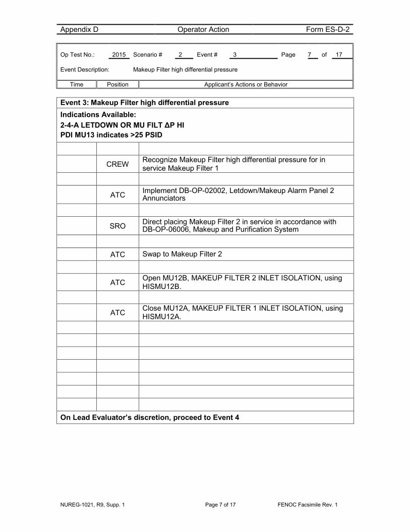
Event 3: Makeup Filter high differential pressure Indications Available: 2-4-A LETDOWN OR MU FILT ΔP HI PDI MU13 indicates >25 PSID
CREW Recognize Makeup Filter high differential pressure for in service Makeup Filter 1
ATC Implement DB-OP-02002, Letdown/Makeup Alarm Panel 2 Annunciators
SRO Direct placing Makeup Filter 2 in service in accordance with DB-OP-06006, Makeup and Purification System
ATC Swap to Makeup Filter 2
ATC Open MU12B, MAKEUP FILTER 2 INLET ISOLATION, using HISMU12B.
ATC Close MU12A, MAKEUP FILTER 1 INLET ISOLATION, using HISMU12A.
On Lead Evaluator’s discretion, proceed to Event 4

Appendix D Operator Action Form ES-D-2 Op Test No.: 2015 Scenario # 2 Event # 4 Page 8 of 17 Event Description: Deaerator level transmitter fails low over a ramp
Time Position Applicant’s Actions or Behavior
NUREG-1021, R9, Supp. 1 Page 8 of 17 FENOC Facsimile Rev. 1
Event 4: Deaerator level transmitter fails low Indications Available: 13-4-C, DEAR STRG TK 1 LVL 13-4-D, DEAR STRG TK 2 LVL (may also alarm) Level indicator failed low (Indicator to LIC CD421) Actual Deaerator Level rising as LCV opens
CREW Recognize Deaerator Storage Tank 1 level
BOP Diagnose high Deaerator Storage Tank 1 water level as indicated at LI 202, DEAERATOR STORAGE TANK 1.
BOP Implement DB-OP-02013, Condensate Feedwater Alarm Panel Annunciators
BOP Verify the proper number of Condensate Pumps are in operation for the present unit load
BOP Diagnose Deaerator Storage Tank 1 level transmitter failure
BOP
Manually control Deaerator 1 level by manually controlling CD-421 using LIC-421 and throttling closed (may also take CD-420 to manual for Deaerator 2)
Booth Cue
Role play as an Equipment Operator to investigate CD420 and CD421 Report valves appear to be working normally
Booth
Cue Role play as Maintenance/Work Week Manager/Field Supervisor to initiate repair of level transmitter
On Lead Evaluator’s discretion, proceed to Event 5

Appendix D Operator Action Form ES-D-2 Op Test No.: 2015 Scenario # 2 Event # 5 Page 9 of 17 Event Description: Oil Leak On Containment Spray Pump 1
Time Position Applicant’s Actions or Behavior
NUREG-1021, R9, Supp. 1 Page 9 of 17 FENOC Facsimile Rev. 1
Event 5: Oil Leak on Containment Spray Pump 1 Indications Available: Equipment Operator report
Booth Cue
Role play as Equipment operator and report “Containment Spray Pump 1 inboard bearing has a severe oil leak and no level is indicated. The sight glass is broken and will need replaced.”
SRO May contact Maintenance and/or Work Week Manager
Booth Cue
If necessary, role play as maintenance and report “Containment Spray Pump 1 will be required to be removed from service to repair broken sight glass”
SRO Declare Containment Spray Pump 1 Inoperable
• Enter Tech Spec 3.6.6, Condition A
SRO Dispatch Operator to remove close power fuses for BE111, Containment Spray Pump 1
Booth Cue
Role play as Equipment Operator to remove close power fuses for BE111, Containment Spray Pump 1
BOP Turn on CS Pump 1 Blue Operability Light
On Lead Evaluator’s discretion after Tech Spec has been entered, proceed to Event 5
Appendix D Operator Action Form ES-D-2 Op Test No.: 2015 Scenario # 2 Event # 7 Page 10 of 17 Event Description: Power Range Nuclear Instrument Failure
Time Position Applicant’s Actions or Behavior
NUREG-1021, R9, Supp. 1 Page 10 of 17 FENOC Facsimile Rev. 1
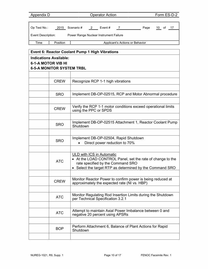
Event 6: Reactor Coolant Pump 1 High Vibrations Indications Available: 6-1-A MOTOR VIB HI 6-5-A MONITOR SYSTEM TRBL
CREW Recognize RCP 1-1 high vibrations
SRO Implement DB-OP-02515, RCP and Motor Abnormal procedure
CREW Verify the RCP 1-1 motor conditions exceed operational limits using the PPC or SPDS
SRO Implement DB-OP-02515 Attachment 1, Reactor Coolant Pump Shutdown
SRO Implement DB-OP-02504, Rapid Shutdown
• Direct power reduction to 70%
ATC
ULD with ICS in Automatic • At the LOAD CONTROL Panel, set the rate of change to the
rate specified by the Command SRO • Select the target RTP as determined by the Command SRO
CREW Monitor Reactor Power to confirm power is being reduced at approximately the expected rate (NI vs. HBP)
ATC Monitor Regulating Rod Insertion Limits during the Shutdown per Technical Specification 3.2.1
ATC Attempt to maintain Axial Power Imbalance between 0 and negative 20 percent using APSRs
BOP Perform Attachment 6, Balance of Plant Actions for Rapid Shutdown

Appendix D Operator Action Form ES-D-2 Op Test No.: 2015 Scenario # 2 Event # 7 Page 11 of 17 Event Description: Power Range Nuclear Instrument Failure
Time Position Applicant’s Actions or Behavior
NUREG-1021, R9, Supp. 1 Page 11 of 17 FENOC Facsimile Rev. 1
Event 6: Reactor Coolant Pump 1 High Vibrations - continued
BOP At approximately 90 percent power, notify the Field Supervisor to remove the Auxiliary Feed Pump Turbine Main Steam Minimum flow lines from service
BOP When Condensate flow is less than 7.0 MPPH (FI578), then establish two Condensate pumps in operation
SRO Notify the System Control Center (SCC) Load Dispatcher of the unit load reduction
BOP Place the ΔTc controller in Automatic
ATC Reduce reactor power to < 72 percent
ATC Stop RCP 1-1
BOP Verify proper Feedwater flow ratios of 2.4 to 1
BOP
Recognize auto re-ratio is not occurring: • Take both FW Loop Demands to Hand • Ratio FW to approximately 2.38 MPPH on SG1 • Ratio FW to approximately 5.74 MPPH on SG2
ATC Verify Tave control is on RCS Loop 2
SRO Check RCS flow is greater than the flow required by TS 3.4.1, DNB Limits. REFER TO DB-OP-03006, Miscellaneous Instrument Shift Checks. (Computer Point F744)
SRO Notify I&C to reduce the RPS High Flux Trip setpoints within 10 hours
On Lead Evaluator’s discretion proceed to Event 7 Event 7: 3 Power Range
Appendix D Operator Action Form ES-D-2 Op Test No.: 2015 Scenario # 2 Event # 7 Page 12 of 17 Event Description: Power Range Nuclear Instrument Failure
Time Position Applicant’s Actions or Behavior
NUREG-1021, R9, Supp. 1 Page 12 of 17 FENOC Facsimile Rev. 1
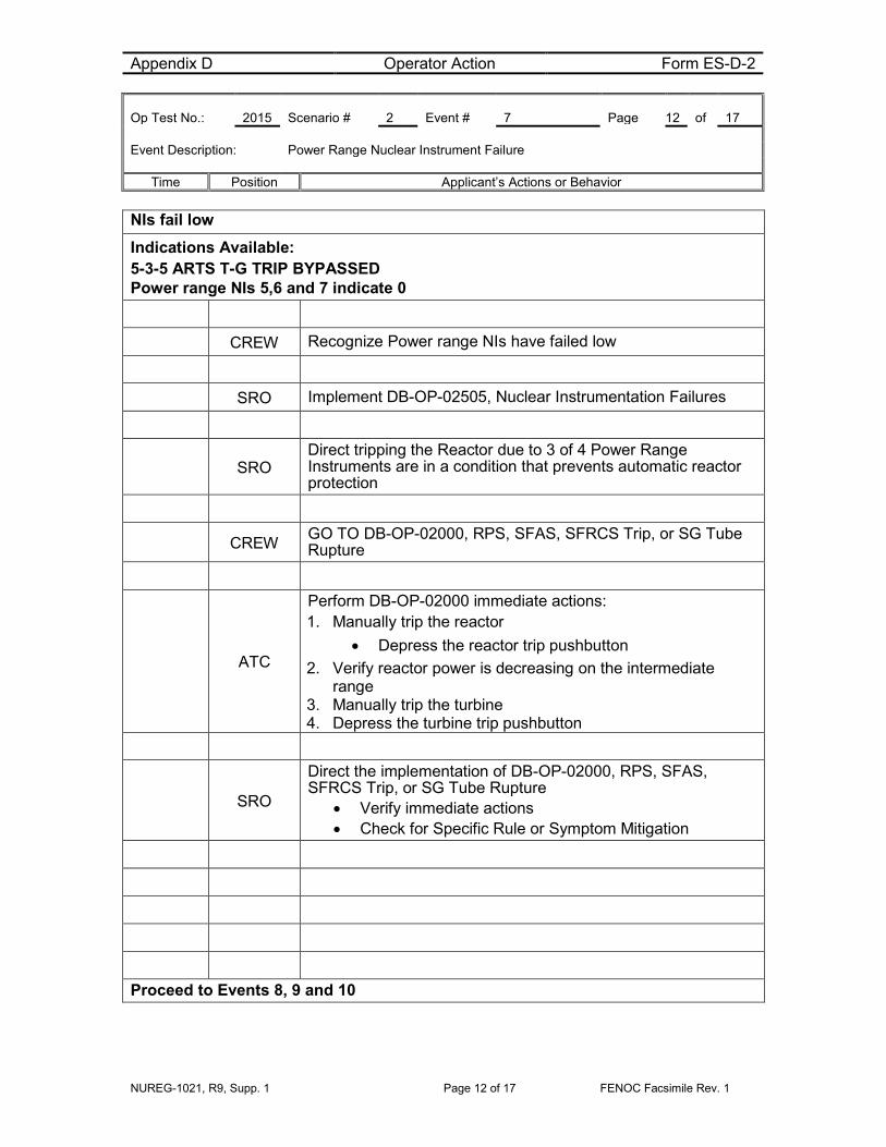
NIs fail low
Indications Available: 5-3-5 ARTS T-G TRIP BYPASSED Power range NIs 5,6 and 7 indicate 0
CREW Recognize Power range NIs have failed low
SRO Implement DB-OP-02505, Nuclear Instrumentation Failures
SRO Direct tripping the Reactor due to 3 of 4 Power Range Instruments are in a condition that prevents automatic reactor protection
CREW GO TO DB-OP-02000, RPS, SFAS, SFRCS Trip, or SG Tube Rupture
ATC
Perform DB-OP-02000 immediate actions: 1. Manually trip the reactor
• Depress the reactor trip pushbutton 2. Verify reactor power is decreasing on the intermediate
range 3. Manually trip the turbine 4. Depress the turbine trip pushbutton
SRO
Direct the implementation of DB-OP-02000, RPS, SFAS, SFRCS Trip, or SG Tube Rupture
• Verify immediate actions • Check for Specific Rule or Symptom Mitigation
Proceed to Events 8, 9 and 10

Appendix D Operator Action Form ES-D-2 Op Test No.: 2015 Scenario # 2 Event # 8, 9 and 10 Page 13 of 17 Event Description: Loss of Offsite power, RCS Leak, EDG 2 trips after starting
Time Position Applicant’s Actions or Behavior
NUREG-1021, R9, Supp. 1 Page 13 of 17 FENOC Facsimile Rev. 1
Event 8: Loss of Offsite Power Event 9: Reactor Coolant System Leak Event 10: Emergency Diesel Generator 2 trips Indications Available: Loss of Control Room Lighting Loss of Subcooling Margin
CREW Recognize loss of all AC Power
BOP
Specific Rule 6 • Recognize C1 and D1 are de-energized • Recognize EDG 1 is OOS and EDG 2 has a fault • Dispatch an Equipment Operator to EDG 2
*Critical Task BOP
Energize D2 Bus by performing Attachment 28, Restore Power to C1 or D1 from the SBODG • Verify ABDD2 is open • Verify AD110 is open • *Start the SBODG • Verify AD213 is closed • *Close AD 301
*Critical Task BOP
Energize C1 • Verify HBBD is open • *Close ABDD2 • *Close ABDC1 OR Energize D1 • *Close AD110

Appendix D Operator Action Form ES-D-2 Op Test No.: 2015 Scenario # 2 Event # 8, 9 and 10 Page 14 of 17 Event Description: Loss of Offsite power, RCS Leak, EDG 2 trips after starting
Time Position Applicant’s Actions or Behavior
NUREG-1021, R9, Supp. 1 Page 14 of 17 FENOC Facsimile Rev. 1
Events 8, 9 and 10 continued
BOP
Perform Specific Rule 4 • Verify proper AFW actuation • Refer to Attachment 3 for AVV control • Verify D2 Bus is energized • Verify an air compressor is running • Control RCS temperature constant or slightly lowering
CREW DB-OP-02000 check for Symptoms
SRO Route to Section 5, Loss of Subcooling Margin
CREW Verify all RCPs are tripped
*Critical Task BOP
Implement Attachment 8, Place MU/HPI/LPI in Service as equipment is available • Start/Verify running a CCW Pump • *Manually start a HPI Pump (auto start is failed) • *Open HP 2A and HP 2B OR HP 2C and HP 2D • Refer to Attachment 11, HPI Flow Balancing • Start a LPI Pump • Open DH 64 OR DH 63 • Transfer a MU Pump suction to the BWST • Set Pressurizer Level Controller to 100 inches • Close MU 19 • Close MU 32 • *Start a Makeup Pump • *Control Pressurizer level using MU 32 or Alternate Injection
Line
ATC If Pressurizer level is < 40 inches and as equipment becomes

Appendix D Operator Action Form ES-D-2 Op Test No.: 2015 Scenario # 2 Event # 8, 9 and 10 Page 15 of 17 Event Description: Loss of Offsite power, RCS Leak, EDG 2 trips after starting
Time Position Applicant’s Actions or Behavior
NUREG-1021, R9, Supp. 1 Page 15 of 17 FENOC Facsimile Rev. 1
available: • Lock the running MU Pump suction on the BWST • Isolate Letdown • Verify Pressurizer heaters are off • Open MU 6421 (if 2 Makeup Pumps are running) • Open MU 6419 (if 2 Makeup Pumps are running) • Direct an Equipment Operator to open MU6423B
ATC Verify proper SFAS actuation
BOP Verify proper SFRCS actuation
BOP Verify proper SG level control
BOP Realign AFW if an SFRCS low pressure trip occurs
CREW Check for Overcooling
CREW Check for ICC Conditions
CREW Monitor for adequate Subcooling Margin
ATC When Subcooling Margin is regained throttle Makeup and/or HPI as necessary per Specific Rule 3
Note: Not required to wait for subcooling margin to be regained to terminate scenario
When DB-OP-02000, Attachment 8, Place HPI/LPI/MU is complete - Scenario may be terminated at Lead Evaluators discretion

NUREG-1021, R9, Supp. 1 Page 16 of 17 FENOC Facsimile Rev. 1
Justification for Critical Tasks
A. Electrical Power Alignment,(CT- 8)
Loss of Emergency Generator 2 with a loss of off-site power and Emergency Generator 1 out of service results in a station blackout. The Station Blackout Diesel Generator will be required to be placed in service to supply an essential bus.
B. Initiate High Pressure Injection (CT- 2)
The Reactor Coolant System Leak that develops following the loss of off-site power will result in a loss of subcooling margin. Once an essential bus is powered by the Station Blackout Diesel Generator High Pressure Injection will be required to be placed in service to restore Reactor Coolant System inventory and subcooling margin

NUREG-1021, R9, Supp. 1 Page 17 of 17 FENOC Facsimile Rev. 1
SIMULATOR SETUP INFORMATION 1. Simulator Setup
a) Emergency Diesel Generator 1 Out of Service
b) Makeup Filter 1 in service
c) EDG trip after auto start
d) HPI auto start prohibited
2. Procedures
a) DB-OP-02001, Electrical Distribution Panel 1 Annunciators
b) DB-OP-2102, Startup Transformer 02 Alarm Panel 102 Annunciators for alarm 102-7-A
c) DB-OP-06311, 345KV Switchyard Procedure
d) DB-OP-02000, Letdown/Makeup Alarm Panel 2 Annunciators
e) DB-OP-02013, Condensate Feedwater Alarm Panel Annunciators
f) DB-OP-02515, RCP and Motor Abnormal procedure
g) DB-OP-02504, Rapid Shutdown
h) DB-OP-02000, RPS, SFAS, SFRCS Trip, or Steam Generator Tube Rupture
3. For Simulator Instructor:
a) DB-OP-06311, Switchyard, Main Transformer, Auxiliary Transformer and Startup Transformers, Section 3.17
b) DB-OP-02001 for 1-1-G
c) DB-OP-02504, Rapid Shutdown Attachment 15
4. For Normal Evolution a) DB-OP-06224 Section 3.24 and 3.25

Appendix D Scenario Outline Form ES-D-1
NUREG-1021, R9 Supp. 1 Page 1 of 16 FENOC Facsimile AG
Facility: Davis-Besse Scenario No.: 3 Op Test No.: NRC 2015
Examiners: Operators: SRO
ATC
BOP
Initial Conditions: • 70% Power • RCP 1-1 OOS • EDG 1 OOS
Turnover: Maintain 70% Power
Planned: Perform MFPT 1 Stop Valve Test, DB-SS-04052
Critical tasks: 1. Establish FW flow and feed SGs (CT-10)
2. Control HPI (CT-5)
3. Close RC11 PORV Block Valve (Emergent)
Event No.
Malf. No.
Event Type* Event Description
1 N-BOP/SRO MFPT 1 Stop Valve Test, DB-SS-04052
2 C-ATC/SRO (TS) PORV Leakage
3 I-ATC/BOP
SRO RCS Hot Leg RTD slowly drifts HI
4 C-BOP MFPT Low Oil pressure – trip MFPT
5 R-ATC
SRO (TS) Dropped Rod – Power reduction
6 Major SG Tube Rupture – trip Reactor
7 C-BOP/SRO Loss of Feedwater -SFRCS fails auto actuation
8 C-ATC/SRO PZR Spray valve fails closed
* (N)ormal, (R)eactivity, (I)nstrument, (C)omponent, (M)ajor

Scenario Event Summary
NUREG-1021, R9 Supp. 1 Page 2 of 16 FENOC Facsimile AG
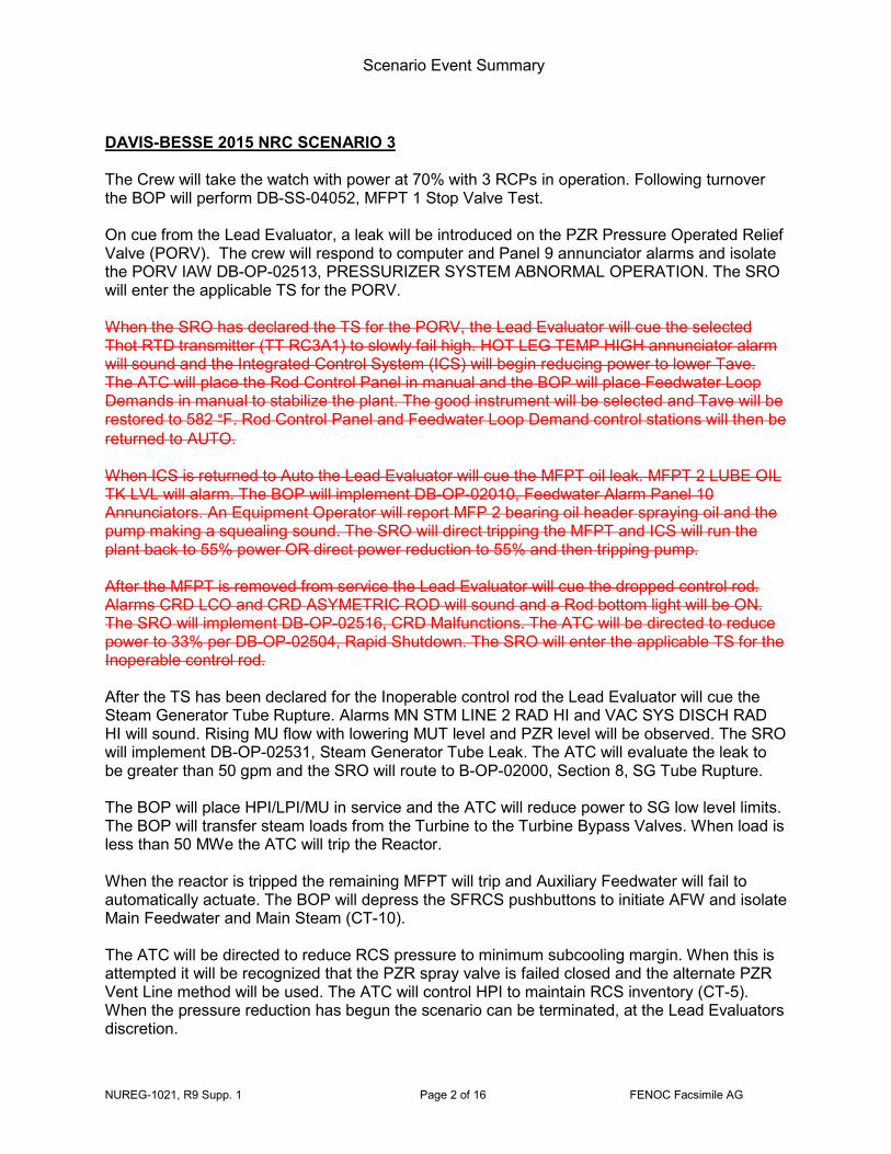
DAVIS-BESSE 2015 NRC SCENARIO 3 The Crew will take the watch with power at 70% with 3 RCPs in operation. Following turnover the BOP will perform DB-SS-04052, MFPT 1 Stop Valve Test. On cue from the Lead Evaluator, a leak will be introduced on the PZR Pressure Operated Relief Valve (PORV). The crew will respond to computer and Panel 9 annunciator alarms and isolate the PORV IAW DB-OP-02513, PRESSURIZER SYSTEM ABNORMAL OPERATION. The SRO will enter the applicable TS for the PORV. When the SRO has declared the TS for the PORV, the Lead Evaluator will cue the selected Thot RTD transmitter (TT RC3A1) to slowly fail high. HOT LEG TEMP HIGH annunciator alarm will sound and the Integrated Control System (ICS) will begin reducing power to lower Tave. The ATC will place the Rod Control Panel in manual and the BOP will place Feedwater Loop Demands in manual to stabilize the plant. The good instrument will be selected and Tave will be restored to 582 °F. Rod Control Panel and Feedwater Loop Demand control stations will then be returned to AUTO. When ICS is returned to Auto the Lead Evaluator will cue the MFPT oil leak. MFPT 2 LUBE OIL TK LVL will alarm. The BOP will implement DB-OP-02010, Feedwater Alarm Panel 10 Annunciators. An Equipment Operator will report MFP 2 bearing oil header spraying oil and the pump making a squealing sound. The SRO will direct tripping the MFPT and ICS will run the plant back to 55% power OR direct power reduction to 55% and then tripping pump. After the MFPT is removed from service the Lead Evaluator will cue the dropped control rod. Alarms CRD LCO and CRD ASYMETRIC ROD will sound and a Rod bottom light will be ON. The SRO will implement DB-OP-02516, CRD Malfunctions. The ATC will be directed to reduce power to 33% per DB-OP-02504, Rapid Shutdown. The SRO will enter the applicable TS for the Inoperable control rod. After the TS has been declared for the Inoperable control rod the Lead Evaluator will cue the Steam Generator Tube Rupture. Alarms MN STM LINE 2 RAD HI and VAC SYS DISCH RAD HI will sound. Rising MU flow with lowering MUT level and PZR level will be observed. The SRO will implement DB-OP-02531, Steam Generator Tube Leak. The ATC will evaluate the leak to be greater than 50 gpm and the SRO will route to B-OP-02000, Section 8, SG Tube Rupture. The BOP will place HPI/LPI/MU in service and the ATC will reduce power to SG low level limits. The BOP will transfer steam loads from the Turbine to the Turbine Bypass Valves. When load is less than 50 MWe the ATC will trip the Reactor. When the reactor is tripped the remaining MFPT will trip and Auxiliary Feedwater will fail to automatically actuate. The BOP will depress the SFRCS pushbuttons to initiate AFW and isolate Main Feedwater and Main Steam (CT-10). The ATC will be directed to reduce RCS pressure to minimum subcooling margin. When this is attempted it will be recognized that the PZR spray valve is failed closed and the alternate PZR Vent Line method will be used. The ATC will control HPI to maintain RCS inventory (CT-5). When the pressure reduction has begun the scenario can be terminated, at the Lead Evaluators discretion.

Appendix D Operator Action Form ES-D-2 Op Test No.: 2015 Scenario # 3 Event # 1 Page 3 of Event Description: Perform DB-SS-04052, MFPT 1 Stop Valves Periodic Test
Time Position Applicant’s Actions or Behavior
NUREG-1021, R9 Supp. 1 Page 3 of 16 FENOC Facsimile Rev. 1
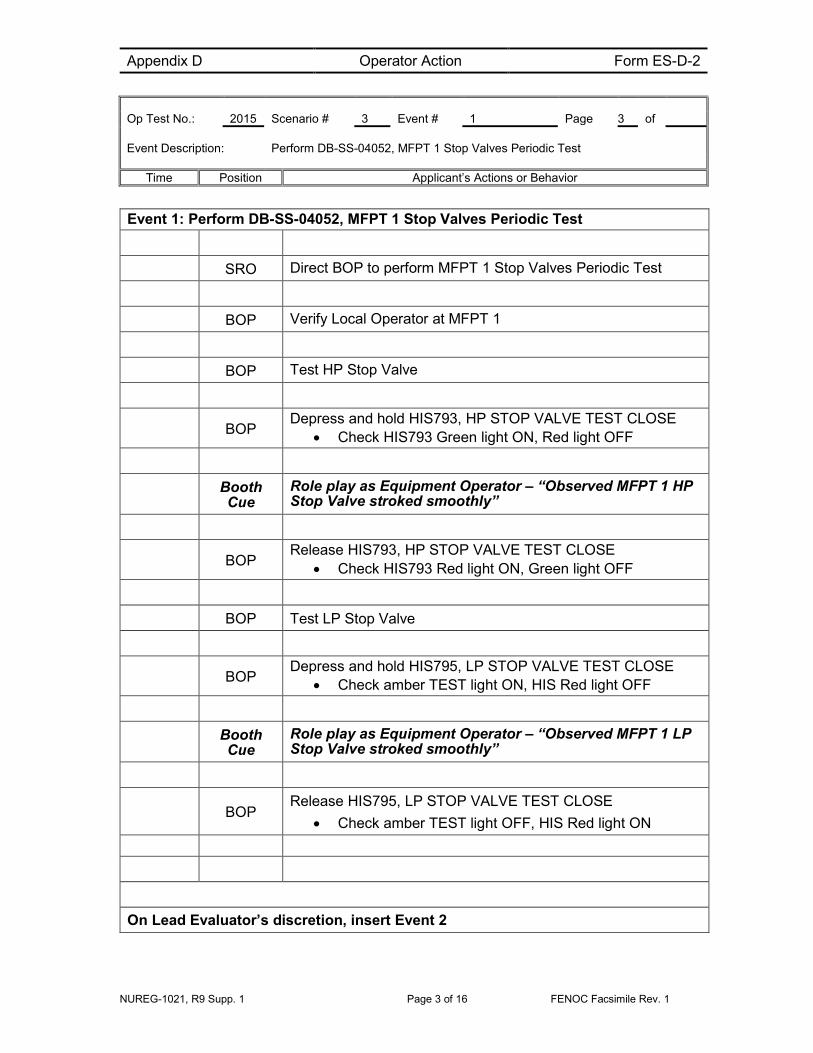
Event 1: Perform DB-SS-04052, MFPT 1 Stop Valves Periodic Test
SRO Direct BOP to perform MFPT 1 Stop Valves Periodic Test
BOP Verify Local Operator at MFPT 1
BOP Test HP Stop Valve
BOP Depress and hold HIS793, HP STOP VALVE TEST CLOSE
• Check HIS793 Green light ON, Red light OFF
Booth Cue
Role play as Equipment Operator – “Observed MFPT 1 HP Stop Valve stroked smoothly”
BOP Release HIS793, HP STOP VALVE TEST CLOSE
• Check HIS793 Red light ON, Green light OFF
BOP Test LP Stop Valve
BOP Depress and hold HIS795, LP STOP VALVE TEST CLOSE
• Check amber TEST light ON, HIS Red light OFF
Booth Cue
Role play as Equipment Operator – “Observed MFPT 1 LP Stop Valve stroked smoothly”
BOP Release HIS795, LP STOP VALVE TEST CLOSE
• Check amber TEST light OFF, HIS Red light ON
On Lead Evaluator’s discretion, insert Event 2

Appendix D Operator Action Form ES-D-2 Op Test No.: 2015 Scenario # 3 Event # 2 Page 4 of Event Description: PORV Leakage
Time Position Applicant’s Actions or Behavior
NUREG-1021, R9 Supp. 1 Page 4 of 16 FENOC Facsimile Rev. 1
Event 2: PORV Leakage Indications Available: 4-2-D, PZR QUENCH TANK PRESS HI 4-4-C, HOT LEG PRESS LO T773, RC PRZR PWR RLF OUT TEMP, RC12-1 rising RCS pressure lowering
ATC Refer to DB-OP-02004, Reactor Coolant Alarm Panel 4 Annunciators Procedure
CREW Recognize RCS pressure is lowering -
CREW Diagnose PORV leakage due to computer point T773, RC PRZR PWR RLF OUT TEMP, RC12-1 rising
SRO Implement DB-OP-02513, Pressurizer Systems Abnormal Operating Procedure
SRO Direct closure of RC11, PORV Block valve
*CRITICAL TASK ATC
Close PORV Block • Close RC11 using HISRC11, PORV BLOCK
CREW Determine RCS leakage has stopped
SRO
Refer to Tech Spec 3.4.11 Pressurizer Pilot Operated Relief Valve (PORV)
• Declare PORV INOPERABLE • Enter 3.4.11 Condition A • Remove power from PORV Block valve
SRO Direct open breaker BE1602 for Pressurizer Pilot Operated Relief Valve (PORV) Block Valve

Appendix D Operator Action Form ES-D-2 Op Test No.: 2015 Scenario # 3 Event # 2 Page 5 of Event Description: PORV Leakage
Time Position Applicant’s Actions or Behavior
NUREG-1021, R9 Supp. 1 Page 5 of 16 FENOC Facsimile Rev. 1
Event 2: PORV Leakage - continued Booth
Cue Role play opening BE1602 for PORV Block Valve
SRO Refer to Tech Specs 3.4.13, RCS Operational Leakage
SRO Refer to TRM 8.4.4, Reactor Coolant System Vents
Note DNBR Tech Spec 3.4.1 may be entered and exited during this scenario
On Lead Evaluator’s discretion, proceed to Event 3

Appendix D Operator Action Form ES-D-2 Op Test No.: 2015 Scenario # 3 Event # 3 Page 6 of Event Description: Selected Thot RTD transmitter (TT RC3A1) slowly fails high
Time Position Applicant’s Actions or Behavior
NUREG-1021, R9 Supp. 1 Page 6 of 16 FENOC Facsimile Rev. 1
Event 3: Selected Thot RTD transmitter (TT RC3A1) slowly fails high Indications Available: 4-2-B, HOT LEG TEMP HIGH 14-2-F ICS ULD TRBL 14-4-D, ICS FW LIMITED BY RX POWER 14-4-E, ICS INPUT MISMATCH 14-6-D, ICS IN TRACK 4-2-E, PZR LVL LO
CREW Recognize ICS is reducing Rx power to lower Tave to 582°F
SRO Implement DB-OP-02526, Primary to Secondary Heat Transfer Upset
ATC Place Rod Control Panel in Manual and adjust power
BOP
• Place BOTH FEEDWATER DEMAND H/A Stations in HAND
• Maintain Feedwater flow matched with Plant power
BOP Check DEHC Load Control Center is in Automatic AND controlling Turbine Header Pressure 830 – 930 psig
ATC Check RCS pressure between 2105 and 2205 psig
ATC • Place SG/RX Demand in Hand • Place Reactor Demand in Hand
BOP • Place SG Load Ratio (ΔTc) in Hand
Note DNBR Tech Spec 3.4.1 may be entered and exited during this scenario

Appendix D Operator Action Form ES-D-2 Op Test No.: 2015 Scenario # 3 Event # 3 Page 7 of Event Description: Selected Thot RTD transmitter (TT RC3A1) slowly fails high
Time Position Applicant’s Actions or Behavior
NUREG-1021, R9 Supp. 1 Page 7 of 16 FENOC Facsimile Rev. 1
Event 3: Selected Thot RTD transmitter (TT RC3A1) slowly fails high - continued
SRO
Assign manual control responsibilities and control bands: • Insert or withdraw Control Rods to maintain Reactor Power
within 1% of current power level • Adjust FW Flow to maintain RCS Tave within 2°F of current
temperature • Adjust FW Flow to maintain RCS cold leg differential
temperature within 2 degrees of zero • Maintain Turbine Header Pressure within 10 psig of current
pressure
SRO
Refer to DB-OP-06407, Non-Nuclear Instrumentation System Operating Procedure for transferring NNI Instrument Inputs to ICS Hand/Auto Stations
ATC
Compare Hot Leg Temperature Indicators TI RC3A1 and T1 RC3B1 on RC Panel C5718
• Select the good instrument TTRC3A3 • Reset ICS Mismatch alarm14-4-E in cabinet area per
DB-OP-02014, Panel 14 Annunciator alarms
ATC/BOP
Return Tave to 582 °F • Adjust FW Loop Demands • Adjust Rod positions
SRO Implement DB-OP-02526 Att. 1, Return ICS Stations to AUTO
ATC 1. Place Rod Control Panel in AUTO 2. Place Reactor Demand Station in AUTO
BOP Place BOTH FEEDWATER DEMAND H/A Stations in AUTO
ATC Place SG/RX Demand in AUTO
On Lead Evaluator’s discretion, proceed to Event 4

Appendix D Operator Action Form ES-D-2 Op Test No.: 2015 Scenario # 3 Event # 4 Page 8 of Event Description: MFPT Low Oil pressure – trip MFPT
Time Position Applicant’s Actions or Behavior
NUREG-1021, R9 Supp. 1 Page 8 of 16 FENOC Facsimile Rev. 1
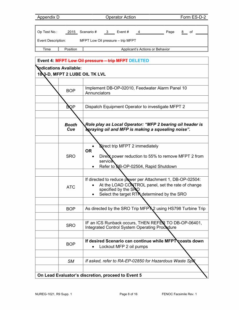
Event 4: MFPT Low Oil pressure – trip MFPT Indications Available: 10-3-D, MFPT 2 LUBE OIL TK LVL
BOP Implement DB-OP-02010, Feedwater Alarm Panel 10 Annunciators
BOP Dispatch Equipment Operator to investigate MFPT 2
Booth Cue
Role play as Local Operator: “MFP 2 bearing oil header is spraying oil and MFP is making a squealing noise”.
SRO
• Direct trip MFPT 2 immediately OR
• Direct power reduction to 55% to remove MFPT 2 from service
• Refer to DB-OP-02504, Rapid Shutdown
ATC
If directed to reduce power per Attachment 1, DB-OP-02504: • At the LOAD CONTROL panel, set the rate of change
specified by the SRO • Select the target RTP determined by the SRO
BOP As directed by the SRO Trip MFPT 2 using HS798 Turbine Trip
SRO IF an ICS Runback occurs, THEN REFER TO DB-OP-06401, Integrated Control System Operating Procedure
BOP If desired Scenario can continue while MFPT coasts down
• Lockout MFP 2 oil pumps
SM If asked, refer to RA-EP-02850 for Hazardous Waste Spill
On Lead Evaluator’s discretion, proceed to Event 5

Appendix D Operator Action Form ES-D-2 Op Test No.: 2015 Scenario # 3 Event # 5 Page 9 of Event Description: Dropped Control Rod
Time Position Applicant’s Actions or Behavior
NUREG-1021, R9 Supp. 1 Page 9 of 16 FENOC Facsimile Rev. 1
Event 5: Dropped Control Rod Indications Available: Annunciator 5-1-E, CRD LCO Annunciator 5-2-E, CRD ASYMETRIC ROD Control Rod 5-8 Rod Bottom light ON
CREW Recognize that a single Control Rod has inserted into the core
SRO Implement DB-OP-02516, CRD Malfunctions
SRO Direct Power reduction to 33% at 3% RTP per minute
ATC • Set ULD MAX LOAD LIMIT to 33% RTP • Set ULD Rate of Change to 3% RTP per minute
SRO Refer to DB-OP-02504, Rapid Shutdown
ATC If annunciator 4-2-E, PZR LEVEL LO alarms due to the dropped rod Tave transient then reduce MU32 (PZR level control) set point to approximately 180 inches
CREW Monitor Reactor Power to confirm power is being reduced at approximately the expected rate
SRO IF Pressurizer Level is greater than 228 inches, then refer to Technical Specification 3.4.9 Condition A
ATC Monitor Regulating Rod Insertion Limits during the Shutdown per Technical Specification 3.2.1
BOP
Perform Attachment 6, Balance of Plant Actions for Rapid Shutdown
• Stop LPFW Drain Pumps • Establish one Condensate Pump in operation • Place S/G Load Ratio H/A in Hand
Appendix D Operator Action Form ES-D-2 Op Test No.: 2015 Scenario # 3 Event # 5 Page 10 of Event Description: Dropped Control Rod
Time Position Applicant’s Actions or Behavior
NUREG-1021, R9 Supp. 1 Page 10 of 16 FENOC Facsimile Rev. 1
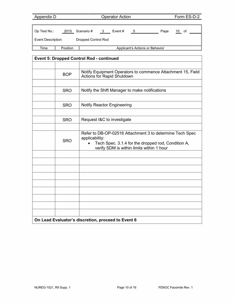
Event 5: Dropped Control Rod - continued
BOP Notify Equipment Operators to commence Attachment 15, Field Actions for Rapid Shutdown
SRO Notify the Shift Manager to make notifications
SRO Notify Reactor Engineering
SRO Request I&C to investigate
SRO
Refer to DB-OP-02516 Attachment 3 to determine Tech Spec applicability:
• Tech Spec. 3.1.4 for the dropped rod, Condition A, verify SDM is within limits within 1 hour
On Lead Evaluator’s discretion, proceed to Event 6

Appendix D Operator Action Form ES-D-2 Op Test No.: 2015 Scenario # 3 Event # 6 Page 11 of Event Description: Steam Generator Tube Rupture
Time Position Applicant’s Actions or Behavior
NUREG-1021, R9 Supp. 1 Page 11 of 16 FENOC Facsimile Rev. 1
Event 6: Steam Generator Tube Rupture Indications Available: 12-1-B MN STM LINE 2 RAD HI 9-4-A VAC SYS DISCH RAD HI High activity on condenser off-gas radiation monitors High activity on either main steam line radiation monitor Increasing Makeup flow
CREW Recognize indications of a tube leak
SRO Implement DB-OP-02531, Steam Generator Tube Leak
ATC Calculate the leak rate using Attachment 1, Steam Generator Tube Leak Rate Calculation (~300 gpm)
SRO Route to DB-OP-02000, SFAS, RPS, SFRCS Trip or SG Tube Rupture, Section 8
ATC Monitor Pressurizer level
• Anytime Pressurizer level is <100 inches – trip Reactor
SRO Notify the Shift Manager to refer to RA-EP-01500, Emergency Classification
*Critical Task BOP
Implement Attachment 8, Place MU/HPI/LPI in Service • Start/Verify running both CCW Pumps • *Start/Verify running both HPI Pumps • *Verify open HP 2A, HP 2B, HP 2C and HP 2D • Start both LPI Pumps • Open DH 64 and DH 63 • Transfer MU Pump suctions to the BWST • Standby Makeup pump does not start
ATC If Pressurizer <200 inches isolate Letdown – Close MU2B
Appendix D Operator Action Form ES-D-2 Op Test No.: 2015 Scenario # 3 Event # 6 Page 12 of Event Description: Steam Generator Tube Rupture
Time Position Applicant’s Actions or Behavior
NUREG-1021, R9 Supp. 1 Page 12 of 16 FENOC Facsimile Rev. 1
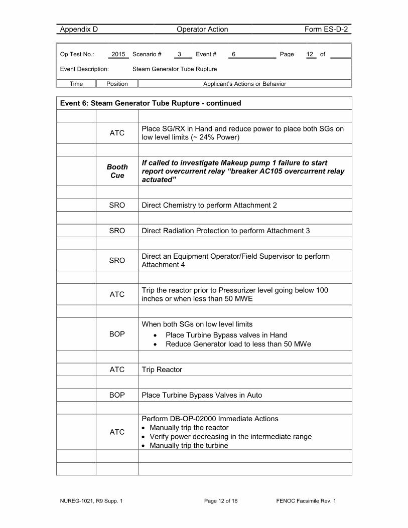
Event 6: Steam Generator Tube Rupture - continued
ATC Place SG/RX in Hand and reduce power to place both SGs on low level limits (~ 24% Power)
Booth Cue
If called to investigate Makeup pump 1 failure to start report overcurrent relay “breaker AC105 overcurrent relay actuated”
SRO Direct Chemistry to perform Attachment 2
SRO Direct Radiation Protection to perform Attachment 3
SRO Direct an Equipment Operator/Field Supervisor to perform Attachment 4
ATC Trip the reactor prior to Pressurizer level going below 100 inches or when less than 50 MWE
BOP When both SGs on low level limits
• Place Turbine Bypass valves in Hand • Reduce Generator load to less than 50 MWe
ATC Trip Reactor
BOP Place Turbine Bypass Valves in Auto
ATC
Perform DB-OP-02000 Immediate Actions • Manually trip the reactor • Verify power decreasing in the intermediate range • Manually trip the turbine

Appendix D Operator Action Form ES-D-2 Op Test No.: 2015 Scenario # 3 Event # 7 & 8 Page 13 of Event Description: Loss of all Feedwater and Pressurizer Spray Valve fails closed
Time Position Applicant’s Actions or Behavior
NUREG-1021, R9 Supp. 1 Page 13 of 16 FENOC Facsimile Rev. 1
Event 7: Loss of Main Feedwater – SFRCS fails to actuate Event 8: Pressurizer Spray valve fails to open for pressure reduction
CREW Implement Specific Rules
*Critical Task BOP
Recognize Main Feedwater is lost and SFRCS is not actuated • Manually Initiate and Isolate SFRCS
CREW Check for Symptoms
SRO Route to section 8 for SG Tube Rupture
BOP Verify Attachment 8 is complete
ATC
If Pressurizer Level is less than 40 inches: • Lock MU Pump suctions on the BWST • Isolate Letdown • Verify Pressurizer heaters are off
ATC Verify Pressurizer level controller set at 100 inches
SRO
Verify DB-OP-02531 Attachments are in progress • Direct Chemistry to perform Attachment 2 • Direct Radiation Protection to perform Attachment 3 • Direct an Equipment Operator/Field Supervisor to perform
Attachment 4
ATC Turn off all Pressurizer heaters
ATC When directed use Pressurizer Spray to reduce RCS pressure - Recognize the Spray valve would not open
SRO Route to step in Section 8.0 for using the Pressurizer Vent for RCS pressure reduction
Event 8: Pressurizer Spray valve fails to open for pressure reduction

Appendix D Operator Action Form ES-D-2 Op Test No.: 2015 Scenario # 3 Event # 7 & 8 Page 14 of Event Description: Loss of all Feedwater and Pressurizer Spray Valve fails closed
Time Position Applicant’s Actions or Behavior
NUREG-1021, R9 Supp. 1 Page 14 of 16 FENOC Facsimile Rev. 1
ATC Start the Quench Tank Circ Pump
ATC Block SFAS low RCS pressure trips when Block Permits light
*Critical Task ATC
Reduce RCS pressure : Pressurizer Vent Line Method • *Open RC 200 • *Open RC 239A • Cycle RC 239A and Pressurizer Heaters to control RCS
Pressure
*Critical Task ATC Throttle High Pressure Injection
• Control Pressurizer level by controlling MU and HPI
When pressure reduction has begun the Scenario can be terminated

NUREG-1021, R9 Supp. 1 Page 15 of 16 FENOC Facsimile Rev. 1
Justification for Critical Tasks A. Establish FW flow and feed SGs (CT-10)
When the Reactor is tripped the remaining Main Feedwater Pump will trip resulting in a loss of Main Feedwater. SFRCS will fail to automatically isolate and actuate Auxiliary Feedwater on Main Feedwater reverse differential pressure as required resulting in a loss of all feedwater. Manual actuation of the SFRCS pushbuttons will be required to restore secondary heat removal
B. Control High Pressure Injection (CT-5)
A Steam Generator Tube Rupture will require High Pressure Injection to be placed in service and throttled to prevent violating the RPV P-T Limit by maintaining RCS inventory and minimum subcooling margin
C. Close RC11, PORV Block Valve (Post Event Emergent Critical Task) PORV (RC2A) leakage will require the closure of RC11 PORV Block Valve to prevent an uncontrolled depressurization of the Reactor Coolant System, over-pressurization of the Pressurizer Quench Tank, and subsequent radioactive release to the Containment.

NUREG-1021, R9 Supp. 1 Page 16 of 16 FENOC Facsimile Rev. 1
SIMULATOR SETUP INFORMATION 1. Simulator Setup
a) 70% Power
b) RCP 1-1 Out of Service
c) Emergency Diesel Generator 1 Out of Service
d) SFRCS Failure to auto trip on loss of Main Feedwater
e) Makeup Pump 1 fails to start
f) PZR Spray valve failed closed on Rx trip
2. Procedures
a) DB-SS-04052, MFPT 1 Stop Valves Periodic Test
b) DB-OP-02004, Reactor Coolant Alarm Panel 4 Annunciators Procedure
c) DB-OP-02513, Pressurizer Systems Abnormal Operation Procedure
d) DB-OP-02526, Primary to Secondary Heat Transfer Upset
e) DB-OP-06407, Non-Nuclear Instrumentation System Operating Procedure
f) DB-OP-02010, Feedwater Alarm Panel 10 Annunciators
g) DB-OP-02504, Rapid Shutdown
h) OP-06401, Integrated Control System Operating Procedure
i) DB-OP-02516, CRD Malfunctions
j) DB-OP-02531, Steam Generator Tube Leak
k) DB-OP-02000, RPS, SFAS, SFRCS Trip, or Steam Generator Tube Rupture
2) For Simulator Instructor:
a) None

Appendix D Scenario Outline Form ES-D-1
NUREG-1021, R9 Supp. 1 Page 1 of 16 FENOC Facsimile AG
Facility: Davis-Besse Scenario No.: 3 Op Test No.: NRC 2015
Examiners: Operators: SRO
ATC
BOP
Initial Conditions: • 70% Power • RCP 1-1 OOS • EDG 1 OOS
Turnover: Maintain 70% Power
Planned: Perform MFPT 1 Stop Valve Test, DB-SS-04052
Critical tasks: 1. Establish FW flow and feed SGs (CT-10)
2. Control HPI (CT-5)
3. Close RC11 PORV Block Valve (Emergent)
Event No.
Malf. No.
Event Type* Event Description
1 N-BOP/SRO MFPT 1 Stop Valve Test, DB-SS-04052
2 C-ATC/SRO (TS) PORV Leakage
3 I-ATC/BOP
SRO RCS Hot Leg RTD slowly drifts HI SEE NOTE BELOW
4 C-BOP MFPT Low Oil pressure – trip MFPT SEE NOTE BELOW
5 R-ATC
SRO (TS) Dropped Rod – Power reduction SEE NOTE BELOW
6 Major SG Tube Rupture – trip Reactor
7 C-BOP/SRO Loss of Feedwater -SFRCS fails auto actuation
8 C-ATC/SRO PZR Spray valve fails closed
NOTE – Events 3, 4, and 5 were not completed due to premature trip of the reactor caused by applicants’ failure to isolate the leaking PORV (Event 2)
* (N)ormal, (R)eactivity, (I)nstrument, (C)omponent, (M)ajor
Scenario Event Summary
NUREG-1021, R9 Supp. 1 Page 2 of 16 FENOC Facsimile AG
DAVIS-BESSE 2015 NRC SCENARIO 3 The Crew will take the watch with power at 70% with 3 RCPs in operation. Following turnover the BOP will perform DB-SS-04052, MFPT 1 Stop Valve Test. On cue from the Lead Evaluator, a leak will be introduced on the PZR Pressure Operated Relief Valve (PORV). The crew will respond to computer and Panel 9 annunciator alarms and isolate the PORV IAW DB-OP-02513, PRESSURIZER SYSTEM ABNORMAL OPERATION. The SRO will enter the applicable TS for the PORV. When the SRO has declared the TS for the PORV, the Lead Evaluator will cue the selected Thot RTD transmitter (TT RC3A1) to slowly fail high. HOT LEG TEMP HIGH annunciator alarm will sound and the Integrated Control System (ICS) will begin reducing power to lower Tave. The ATC will place the Rod Control Panel in manual and the BOP will place Feedwater Loop Demands in manual to stabilize the plant. The good instrument will be selected and Tave will be restored to 582 °F. Rod Control Panel and Feedwater Loop Demand control stations will then be returned to AUTO. When ICS is returned to Auto the Lead Evaluator will cue the MFPT oil leak. MFPT 2 LUBE OIL TK LVL will alarm. The BOP will implement DB-OP-02010, Feedwater Alarm Panel 10 Annunciators. An Equipment Operator will report MFP 2 bearing oil header spraying oil and the pump making a squealing sound. The SRO will direct tripping the MFPT and ICS will run the plant back to 55% power OR direct power reduction to 55% and then tripping pump. After the MFPT is removed from service the Lead Evaluator will cue the dropped control rod. Alarms CRD LCO and CRD ASYMETRIC ROD will sound and a Rod bottom light will be ON. The SRO will implement DB-OP-02516, CRD Malfunctions. The ATC will be directed to reduce power to 33% per DB-OP-02504, Rapid Shutdown. The SRO will enter the applicable TS for the Inoperable control rod. After the TS has been declared for the Inoperable control rod the Lead Evaluator will cue the Steam Generator Tube Rupture. Alarms MN STM LINE 2 RAD HI and VAC SYS DISCH RAD HI will sound. Rising MU flow with lowering MUT level and PZR level will be observed. The SRO will implement DB-OP-02531, Steam Generator Tube Leak. The ATC will evaluate the leak to be greater than 50 gpm and the SRO will route to B-OP-02000, Section 8, SG Tube Rupture. The BOP will place HPI/LPI/MU in service and the ATC will reduce power to SG low level limits. The BOP will transfer steam loads from the Turbine to the Turbine Bypass Valves. When load is less than 50 MWe the ATC will trip the Reactor. When the reactor is tripped the remaining MFPT will trip and Auxiliary Feedwater will fail to automatically actuate. The BOP will depress the SFRCS pushbuttons to initiate AFW and isolate Main Feedwater and Main Steam (CT-10). The ATC will be directed to reduce RCS pressure to minimum subcooling margin. When this is attempted it will be recognized that the PZR spray valve is failed closed and the alternate PZR Vent Line method will be used. The ATC will control HPI to maintain RCS inventory (CT-5). When the pressure reduction has begun the scenario can be terminated, at the Lead Evaluators discretion.
Appendix D Operator Action Form ES-D-2 Op Test No.: 2015 Scenario # 3 Event # 1 Page 3 of Event Description: Perform DB-SS-04052, MFPT 1 Stop Valves Periodic Test
Time Position Applicant’s Actions or Behavior
NUREG-1021, R9 Supp. 1 Page 3 of 16 FENOC Facsimile Rev. 1
Event 1: Perform DB-SS-04052, MFPT 1 Stop Valves Periodic Test
SRO Direct BOP to perform MFPT 1 Stop Valves Periodic Test
BOP Verify Local Operator at MFPT 1
BOP Test HP Stop Valve
BOP Depress and hold HIS793, HP STOP VALVE TEST CLOSE
• Check HIS793 Green light ON, Red light OFF
Booth Cue
Role play as Equipment Operator – “Observed MFPT 1 HP Stop Valve stroked smoothly”
BOP Release HIS793, HP STOP VALVE TEST CLOSE
• Check HIS793 Red light ON, Green light OFF
BOP Test LP Stop Valve
BOP Depress and hold HIS795, LP STOP VALVE TEST CLOSE
• Check amber TEST light ON, HIS Red light OFF
Booth Cue
Role play as Equipment Operator – “Observed MFPT 1 LP Stop Valve stroked smoothly”
BOP Release HIS795, LP STOP VALVE TEST CLOSE
• Check amber TEST light OFF, HIS Red light ON
On Lead Evaluator’s discretion, insert Event 2

Appendix D Operator Action Form ES-D-2 Op Test No.: 2015 Scenario # 3 Event # 2 Page 4 of Event Description: PORV Leakage
Time Position Applicant’s Actions or Behavior
NUREG-1021, R9 Supp. 1 Page 4 of 16 FENOC Facsimile Rev. 1
Event 2: PORV Leakage Indications Available: 4-2-D, PZR QUENCH TANK PRESS HI 4-4-C, HOT LEG PRESS LO T773, RC PRZR PWR RLF OUT TEMP, RC12-1 rising RCS pressure lowering
ATC Refer to DB-OP-02004, Reactor Coolant Alarm Panel 4 Annunciators Procedure
CREW Recognize RCS pressure is lowering -
CREW Diagnose PORV leakage due to computer point T773, RC PRZR PWR RLF OUT TEMP, RC12-1 rising
SRO Implement DB-OP-02513, Pressurizer Systems Abnormal Operating Procedure
SRO Direct closure of RC11, PORV Block valve
*CRITICAL TASK ATC
Close PORV Block • Close RC11 using HISRC11, PORV BLOCK
CREW Determine RCS leakage has stopped
SRO
Refer to Tech Spec 3.4.11 Pressurizer Pilot Operated Relief Valve (PORV)
• Declare PORV INOPERABLE • Enter 3.4.11 Condition A • Remove power from PORV Block valve
SRO Direct open breaker BE1602 for Pressurizer Pilot Operated Relief Valve (PORV) Block Valve

Appendix D Operator Action Form ES-D-2 Op Test No.: 2015 Scenario # 3 Event # 2 Page 5 of Event Description: PORV Leakage
Time Position Applicant’s Actions or Behavior
NUREG-1021, R9 Supp. 1 Page 5 of 16 FENOC Facsimile Rev. 1
Event 2: PORV Leakage - continued Booth
Cue Role play opening BE1602 for PORV Block Valve
SRO Refer to Tech Specs 3.4.13, RCS Operational Leakage
SRO Refer to TRM 8.4.4, Reactor Coolant System Vents
Note DNBR Tech Spec 3.4.1 may be entered and exited during this scenario
On Lead Evaluator’s discretion, proceed to Event 3
Appendix D Operator Action Form ES-D-2 Op Test No.: 2015 Scenario # 3 Event # 3 Page 6 of Event Description: Selected Thot RTD transmitter (TT RC3A1) slowly fails high
Time Position Applicant’s Actions or Behavior
NUREG-1021, R9 Supp. 1 Page 6 of 16 FENOC Facsimile Rev. 1
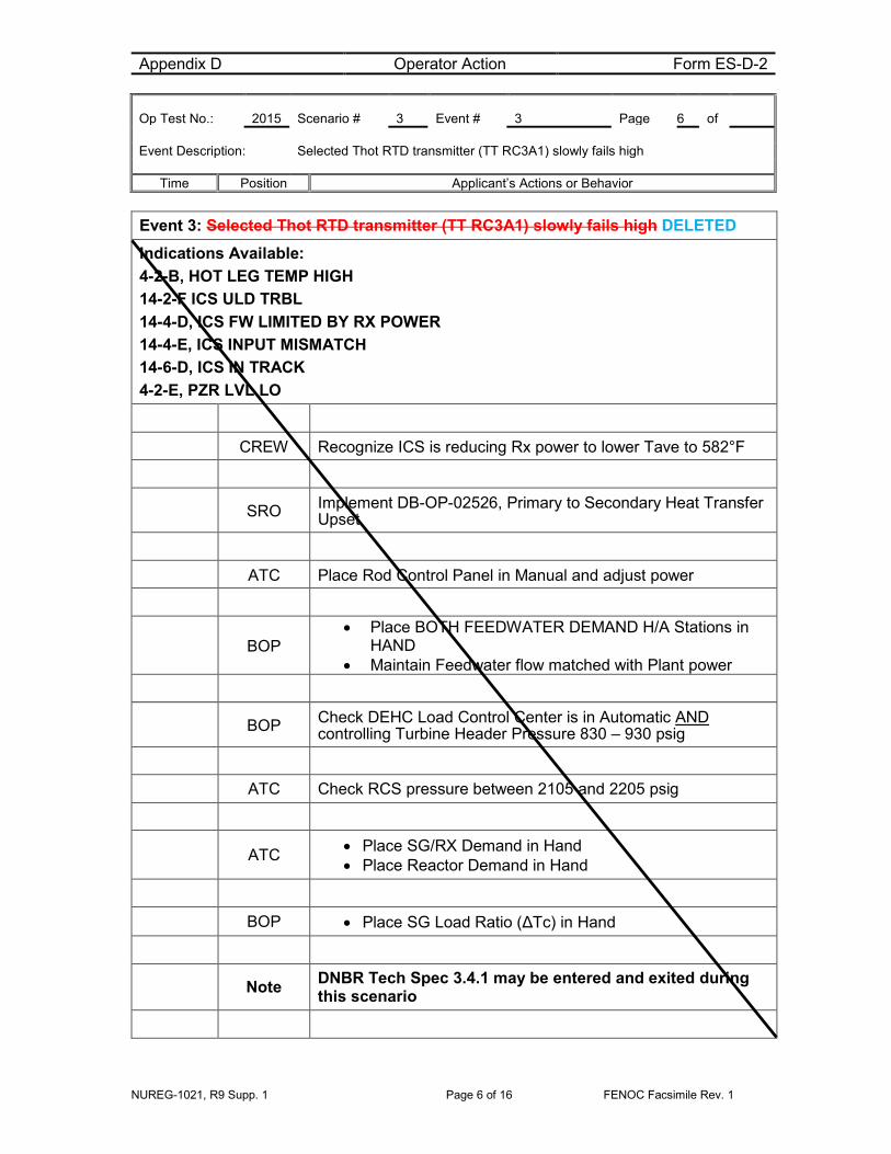
Event 3: Selected Thot RTD transmitter (TT RC3A1) slowly fails high DELETED Indications Available: 4-2-B, HOT LEG TEMP HIGH 14-2-F ICS ULD TRBL 14-4-D, ICS FW LIMITED BY RX POWER 14-4-E, ICS INPUT MISMATCH 14-6-D, ICS IN TRACK 4-2-E, PZR LVL LO
CREW Recognize ICS is reducing Rx power to lower Tave to 582°F
SRO Implement DB-OP-02526, Primary to Secondary Heat Transfer Upset
ATC Place Rod Control Panel in Manual and adjust power
BOP
• Place BOTH FEEDWATER DEMAND H/A Stations in HAND
• Maintain Feedwater flow matched with Plant power
BOP Check DEHC Load Control Center is in Automatic AND controlling Turbine Header Pressure 830 – 930 psig
ATC Check RCS pressure between 2105 and 2205 psig
ATC • Place SG/RX Demand in Hand • Place Reactor Demand in Hand
BOP • Place SG Load Ratio (ΔTc) in Hand
Note DNBR Tech Spec 3.4.1 may be entered and exited during this scenario

Appendix D Operator Action Form ES-D-2 Op Test No.: 2015 Scenario # 3 Event # 3 Page 7 of Event Description: Selected Thot RTD transmitter (TT RC3A1) slowly fails high
Time Position Applicant’s Actions or Behavior
NUREG-1021, R9 Supp. 1 Page 7 of 16 FENOC Facsimile Rev. 1
Event 3: Selected Thot RTD transmitter (TT RC3A1) slowly fails high - continued
SRO Assign manual control responsibilities and control bands: • Insert or withdraw Control Rods to maintain Reactor Power
within 1% of current power level • Adjust FW Flow to maintain RCS Tave within 2°F of current
temperature • Adjust FW Flow to maintain RCS cold leg differential
temperature within 2 degrees of zero • Maintain Turbine Header Pressure within 10 psig of current
pressure
SRO
Refer to DB-OP-06407, Non-Nuclear Instrumentation System Operating Procedure for transferring NNI Instrument Inputs to ICS Hand/Auto Stations
ATC
Compare Hot Leg Temperature Indicators TI RC3A1 and T1 RC3B1 on RC Panel C5718
• Select the good instrument TTRC3A3 • Reset ICS Mismatch alarm14-4-E in cabinet area per
DB-OP-02014, Panel 14 Annunciator alarms
ATC/BOP
Return Tave to 582 °F • Adjust FW Loop Demands • Adjust Rod positions
SRO Implement DB-OP-02526 Att. 1, Return ICS Stations to AUTO
ATC 1. Place Rod Control Panel in AUTO 2. Place Reactor Demand Station in AUTO
BOP Place BOTH FEEDWATER DEMAND H/A Stations in AUTO
ATC Place SG/RX Demand in AUTO
On Lead Evaluator’s discretion, proceed to Event 4
Appendix D Operator Action Form ES-D-2 Op Test No.: 2015 Scenario # 3 Event # 4 Page 8 of Event Description: MFPT Low Oil pressure – trip MFPT
Time Position Applicant’s Actions or Behavior
NUREG-1021, R9 Supp. 1 Page 8 of 16 FENOC Facsimile Rev. 1
Event 4: MFPT Low Oil pressure – trip MFPT DELETED Indications Available: 10-3-D, MFPT 2 LUBE OIL TK LVL
BOP Implement DB-OP-02010, Feedwater Alarm Panel 10 Annunciators
BOP Dispatch Equipment Operator to investigate MFPT 2
Booth Cue
Role play as Local Operator: “MFP 2 bearing oil header is spraying oil and MFP is making a squealing noise”.
SRO
• Direct trip MFPT 2 immediately OR
• Direct power reduction to 55% to remove MFPT 2 from service
• Refer to DB-OP-02504, Rapid Shutdown
ATC
If directed to reduce power per Attachment 1, DB-OP-02504: • At the LOAD CONTROL panel, set the rate of change
specified by the SRO • Select the target RTP determined by the SRO
BOP As directed by the SRO Trip MFPT 2 using HS798 Turbine Trip
SRO IF an ICS Runback occurs, THEN REFER TO DB-OP-06401, Integrated Control System Operating Procedure
BOP If desired Scenario can continue while MFPT coasts down
• Lockout MFP 2 oil pumps
SM If asked, refer to RA-EP-02850 for Hazardous Waste Spill
On Lead Evaluator’s discretion, proceed to Event 5
Appendix D Operator Action Form ES-D-2 Op Test No.: 2015 Scenario # 3 Event # 5 Page 9 of Event Description: Dropped Control Rod
Time Position Applicant’s Actions or Behavior
NUREG-1021, R9 Supp. 1 Page 9 of 16 FENOC Facsimile Rev. 1
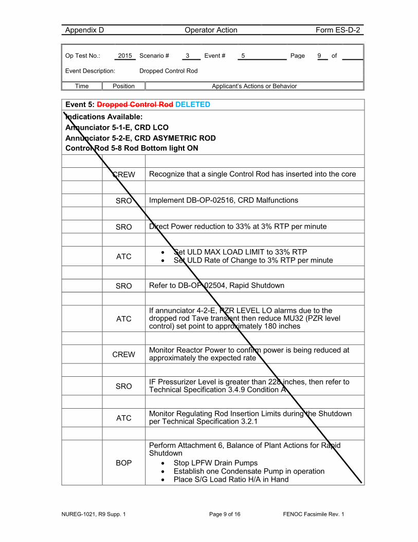
Event 5: Dropped Control Rod DELETED Indications Available: Annunciator 5-1-E, CRD LCO Annunciator 5-2-E, CRD ASYMETRIC ROD Control Rod 5-8 Rod Bottom light ON
CREW Recognize that a single Control Rod has inserted into the core
SRO Implement DB-OP-02516, CRD Malfunctions
SRO Direct Power reduction to 33% at 3% RTP per minute
ATC • Set ULD MAX LOAD LIMIT to 33% RTP • Set ULD Rate of Change to 3% RTP per minute
SRO Refer to DB-OP-02504, Rapid Shutdown
ATC If annunciator 4-2-E, PZR LEVEL LO alarms due to the dropped rod Tave transient then reduce MU32 (PZR level control) set point to approximately 180 inches
CREW Monitor Reactor Power to confirm power is being reduced at approximately the expected rate
SRO IF Pressurizer Level is greater than 228 inches, then refer to Technical Specification 3.4.9 Condition A
ATC Monitor Regulating Rod Insertion Limits during the Shutdown per Technical Specification 3.2.1
BOP
Perform Attachment 6, Balance of Plant Actions for Rapid Shutdown
• Stop LPFW Drain Pumps • Establish one Condensate Pump in operation • Place S/G Load Ratio H/A in Hand

Appendix D Operator Action Form ES-D-2 Op Test No.: 2015 Scenario # 3 Event # 5 Page 10 of Event Description: Dropped Control Rod
Time Position Applicant’s Actions or Behavior
NUREG-1021, R9 Supp. 1 Page 10 of 16 FENOC Facsimile Rev. 1
Event 5: Dropped Control Rod - continued
BOP Notify Equipment Operators to commence Attachment 15, Field Actions for Rapid Shutdown
SRO Notify the Shift Manager to make notifications
SRO Notify Reactor Engineering
SRO Request I&C to investigate
SRO
Refer to DB-OP-02516 Attachment 3 to determine Tech Spec applicability:
• Tech Spec. 3.1.4 for the dropped rod, Condition A, verify SDM is within limits within 1 hour
On Lead Evaluator’s discretion, proceed to Event 6

Appendix D Operator Action Form ES-D-2 Op Test No.: 2015 Scenario # 3 Event # 6 Page 11 of Event Description: Steam Generator Tube Rupture
Time Position Applicant’s Actions or Behavior
NUREG-1021, R9 Supp. 1 Page 11 of 16 FENOC Facsimile Rev. 1
Event 6: Steam Generator Tube Rupture Indications Available: 12-1-B MN STM LINE 2 RAD HI 9-4-A VAC SYS DISCH RAD HI High activity on condenser off-gas radiation monitors High activity on either main steam line radiation monitor Increasing Makeup flow
CREW Recognize indications of a tube leak
SRO Implement DB-OP-02531, Steam Generator Tube Leak
ATC Calculate the leak rate using Attachment 1, Steam Generator Tube Leak Rate Calculation (~300 gpm)
SRO Route to DB-OP-02000, SFAS, RPS, SFRCS Trip or SG Tube Rupture, Section 8
ATC Monitor Pressurizer level
• Anytime Pressurizer level is <100 inches – trip Reactor
SRO Notify the Shift Manager to refer to RA-EP-01500, Emergency Classification
*Critical Task BOP
Implement Attachment 8, Place MU/HPI/LPI in Service • Start/Verify running both CCW Pumps • *Start/Verify running both HPI Pumps • *Verify open HP 2A, HP 2B, HP 2C and HP 2D • Start both LPI Pumps • Open DH 64 and DH 63 • Transfer MU Pump suctions to the BWST • Standby Makeup pump does not start
ATC If Pressurizer <200 inches isolate Letdown – Close MU2B

Appendix D Operator Action Form ES-D-2 Op Test No.: 2015 Scenario # 3 Event # 6 Page 12 of Event Description: Steam Generator Tube Rupture
Time Position Applicant’s Actions or Behavior
NUREG-1021, R9 Supp. 1 Page 12 of 16 FENOC Facsimile Rev. 1
Event 6: Steam Generator Tube Rupture - continued
ATC Place SG/RX in Hand and reduce power to place both SGs on low level limits (~ 24% Power)
Booth Cue
If called to investigate Makeup pump 1 failure to start report overcurrent relay “breaker AC105 overcurrent relay actuated”
SRO Direct Chemistry to perform Attachment 2
SRO Direct Radiation Protection to perform Attachment 3
SRO Direct an Equipment Operator/Field Supervisor to perform Attachment 4
ATC Trip the reactor prior to Pressurizer level going below 100 inches or when less than 50 MWE
BOP When both SGs on low level limits
• Place Turbine Bypass valves in Hand • Reduce Generator load to less than 50 MWe
ATC Trip Reactor
BOP Place Turbine Bypass Valves in Auto
ATC
Perform DB-OP-02000 Immediate Actions • Manually trip the reactor • Verify power decreasing in the intermediate range • Manually trip the turbine

Appendix D Operator Action Form ES-D-2 Op Test No.: 2015 Scenario # 3 Event # 7 & 8 Page 13 of Event Description: Loss of all Feedwater and Pressurizer Spray Valve fails closed
Time Position Applicant’s Actions or Behavior
NUREG-1021, R9 Supp. 1 Page 13 of 16 FENOC Facsimile Rev. 1
Event 7: Loss of Main Feedwater – SFRCS fails to actuate Event 8: Pressurizer Spray valve fails to open for pressure reduction
CREW Implement Specific Rules
*Critical Task BOP
Recognize Main Feedwater is lost and SFRCS is not actuated • Manually Initiate and Isolate SFRCS
CREW Check for Symptoms
SRO Route to section 8 for SG Tube Rupture
BOP Verify Attachment 8 is complete
ATC
If Pressurizer Level is less than 40 inches: • Lock MU Pump suctions on the BWST • Isolate Letdown • Verify Pressurizer heaters are off
ATC Verify Pressurizer level controller set at 100 inches
SRO
Verify DB-OP-02531 Attachments are in progress • Direct Chemistry to perform Attachment 2 • Direct Radiation Protection to perform Attachment 3 • Direct an Equipment Operator/Field Supervisor to perform
Attachment 4
ATC Turn off all Pressurizer heaters
ATC When directed use Pressurizer Spray to reduce RCS pressure - Recognize the Spray valve would not open
SRO Route to step in Section 8.0 for using the Pressurizer Vent for RCS pressure reduction
Event 8: Pressurizer Spray valve fails to open for pressure reduction

Appendix D Operator Action Form ES-D-2 Op Test No.: 2015 Scenario # 3 Event # 7 & 8 Page 14 of Event Description: Loss of all Feedwater and Pressurizer Spray Valve fails closed
Time Position Applicant’s Actions or Behavior
NUREG-1021, R9 Supp. 1 Page 14 of 16 FENOC Facsimile Rev. 1
ATC Start the Quench Tank Circ Pump
ATC Block SFAS low RCS pressure trips when Block Permits light
*Critical Task ATC
Reduce RCS pressure : Pressurizer Vent Line Method • *Open RC 200 • *Open RC 239A • Cycle RC 239A and Pressurizer Heaters to control RCS
Pressure
*Critical Task ATC Throttle High Pressure Injection
• Control Pressurizer level by controlling MU and HPI
When pressure reduction has begun the Scenario can be terminated

NUREG-1021, R9 Supp. 1 Page 15 of 16 FENOC Facsimile Rev. 1
Justification for Critical Tasks A. Establish FW flow and feed SGs (CT-10)
When the Reactor is tripped the remaining Main Feedwater Pump will trip resulting in a loss of Main Feedwater. SFRCS will fail to automatically isolate and actuate Auxiliary Feedwater on Main Feedwater reverse differential pressure as required resulting in a loss of all feedwater. Manual actuation of the SFRCS pushbuttons will be required to restore secondary heat removal
B. Control High Pressure Injection (CT-5)
A Steam Generator Tube Rupture will require High Pressure Injection to be placed in service and throttled to prevent violating the RPV P-T Limit by maintaining RCS inventory and minimum subcooling margin
C. Close RC11, PORV Block Valve (Post Event Emergent Critical Task) PORV (RC2A) leakage will require the closure of RC11 PORV Block Valve to prevent an uncontrolled depressurization of the Reactor Coolant System, over-pressurization of the Pressurizer Quench Tank, and subsequent radioactive release to the Containment.

NUREG-1021, R9 Supp. 1 Page 16 of 16 FENOC Facsimile Rev. 1
SIMULATOR SETUP INFORMATION 1. Simulator Setup
a) 70% Power
b) RCP 1-1 Out of Service
c) Emergency Diesel Generator 1 Out of Service
d) SFRCS Failure to auto trip on loss of Main Feedwater
e) Makeup Pump 1 fails to start
f) PZR Spray valve failed closed on Rx trip
2. Procedures
a) DB-SS-04052, MFPT 1 Stop Valves Periodic Test
b) DB-OP-02004, Reactor Coolant Alarm Panel 4 Annunciators Procedure
c) DB-OP-02513, Pressurizer Systems Abnormal Operation Procedure
d) DB-OP-02526, Primary to Secondary Heat Transfer Upset
e) DB-OP-06407, Non-Nuclear Instrumentation System Operating Procedure
f) DB-OP-02010, Feedwater Alarm Panel 10 Annunciators
g) DB-OP-02504, Rapid Shutdown
h) OP-06401, Integrated Control System Operating Procedure
i) DB-OP-02516, CRD Malfunctions
j) DB-OP-02531, Steam Generator Tube Leak
k) DB-OP-02000, RPS, SFAS, SFRCS Trip, or Steam Generator Tube Rupture
2) For Simulator Instructor:
a) None
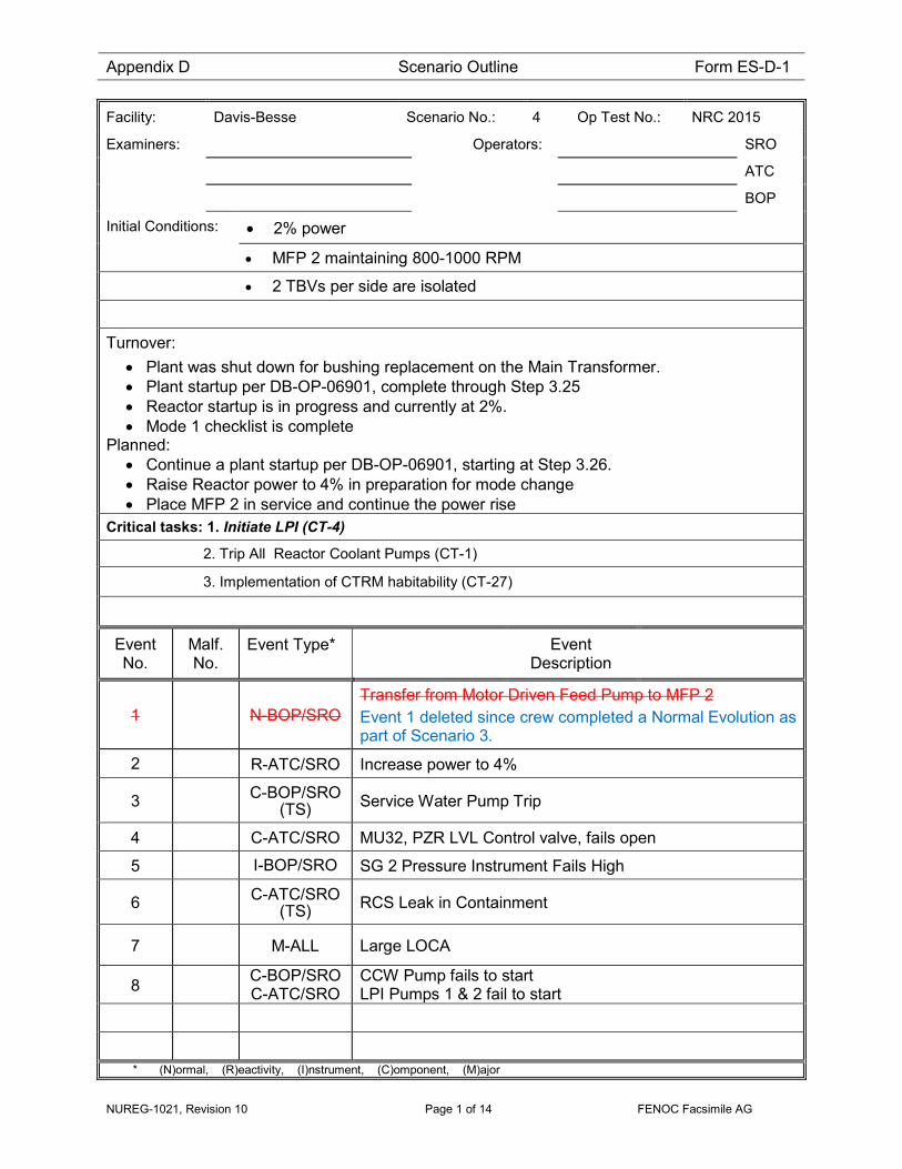
Appendix D Scenario Outline Form ES-D-1
NUREG-1021, Revision 10 Page 1 of 14 FENOC Facsimile AG
Facility: Davis-Besse Scenario No.: 4 Op Test No.: NRC 2015
Examiners: Operators: SRO
ATC
BOP
Initial Conditions: • 2% power
• MFP 2 maintaining 800-1000 RPM
• 2 TBVs per side are isolated
Turnover: • Plant was shut down for bushing replacement on the Main Transformer. • Plant startup per DB-OP-06901, complete through Step 3.25 • Reactor startup is in progress and currently at 2%. • Mode 1 checklist is complete
Planned: • Continue a plant startup per DB-OP-06901, starting at Step 3.26. • Raise Reactor power to 4% in preparation for mode change • Place MFP 2 in service and continue the power rise
Critical tasks: 1. Initiate LPI (CT-4)
2. Trip All Reactor Coolant Pumps (CT-1)
3. Implementation of CTRM habitability (CT-27)
Event No.
Malf. No.
Event Type* Event Description
1 N-BOP/SRO Transfer from Motor Driven Feed Pump to MFP 2 Event 1 deleted since crew completed a Normal Evolution as part of Scenario 3.
2 R-ATC/SRO Increase power to 4%
3 C-BOP/SRO (TS) Service Water Pump Trip
4 C-ATC/SRO MU32, PZR LVL Control valve, fails open
5 I-BOP/SRO SG 2 Pressure Instrument Fails High
6 C-ATC/SRO (TS) RCS Leak in Containment
7 M-ALL Large LOCA
8 C-BOP/SRO C-ATC/SRO
CCW Pump fails to start LPI Pumps 1 & 2 fail to start
* (N)ormal, (R)eactivity, (I)nstrument, (C)omponent, (M)ajor

Scenario Event Summary
NUREG-1021, Revision 10 Page 2 of 14 FENOC Facsimile AG
DAVIS-BESSE 2015 NRC SCENARIO 4 The scenario begins with the plant in Mode 2 ~2% power plant startup in progress. . Aux Boiler is in service. MFP 2 is ready to place in service, currently maintaining 800-1000 RPM. 2 TBVs per side are isolated. DB-OP-06901 is completed up to step 3.27. The BOP will place MFP 2 in service and The ATC will raise Reactor Power while controlling heatup rate at less than 35°F/Hr. The BOP will place the Anticipatory Reactor Trip System (ARTS) test toggle switches for the Operating Main Feed Pump in OPERATE. Once power has been raised to 4% and stabilized the Lead Evaluator can cue the Service Water Pump supplying secondary loads to trip. SW HDR PRESS alarm will sound and the SRO will implement DB-OP-02511, Loss of Service Water Pumps/ System. The BOP will isolate Service Water (SW) to that train Containment Air Cooler (CAC) and verify Circulating Water aligned to cool secondary loads. The SRO will enter the applicable TS and direct the spare SW Pump to be placed in service. The BOP will restore secondary loads and restore CAC SW flow. After Service Water is restored to normal, the Lead Evaluator will cue Normal Makeup Line, MU32, PZR level control valve to fail open. MU FLOW HI TRN 2 will alarm. The ATC will need to isolate MU32 and the SRO will implement DB-OP-02512 Makeup and Purification System Malfunctions for loss of normal makeup and place the alternate injection line in service. When the alternate injection line is placed in service and PZR level is restored, the Lead Evaluator will cue the SG 2 pressure transmitter PT SP12A2 failing high, resulting in SG2 TBVs and AVV opening. The BOP will close the AVV, isolate the in service TBV, select an alternate pressure transmitter and restore the TBV and AVV to service. With the alternate SG 2 pressure transmitter selected and the plant stabilized the Lead Evaluator will cue the RCS leak in Containment. The SRO will implement DB-OP-02522, Small RCS Leaks to mitigate the leak. The reactor will require tripping per immediate actions of DB-OP-02522 due to PZR level below 100 inches. When the Reactor is tripped the RCS leak will increase to a large LOCA. The Emergency Diesel Generators will start on SA level 2 actuation. The standby Component Cooling Water Pump will fail to auto start and will be started from the control panel. Subcooling margin will be lost requiring the RCPs to be tripped (CT-1). Section 5 of DB-OP-02000, Loss of Subcooling Margin, will be entered. Transition will be made to Section 10, Large LOCA. LPI will have failed to auto start and will be initiated manually (CT-4). Control Room EVS will be placed in service (CT-27). When Control Room EVS is placed in service the scenario can be terminated at the Lead Evaluators discretion.

Appendix D Operator Action Form ES-D-2 Op Test No.: 2015 Scenario # 4 Event # 1 & 2 Page 3 of 14 Event Description: Transfer from Motor Driven Feed Pump to Main Feed Pump 2 & increase Power
Time Position Applicant’s Actions or Behavior
NUREG-1021, Revision 10 Page 3 of 14 FENOC Facsimile AG
Event 1: Transfer from Motor Driven Feed Pump to Main Feed Pump 2 DELETED Event 2: Raise Reactor power to 4%
SRO Direct transfer of feedwater from the MDFP to MFP 2
BOP Raise Main Feed Pump Speed until discharge pressure is between 1000 and 1050 psig
BOP Contact Equipment Operator to close FW6396
Booth Cue Role play as equipment operator to close FW6396
BOP Stop the Motor Driven Feed Pump
BOP
Contact Equipment Operator to: • Verify Closed FW170, FW Mini Bypass to condenser • Close FW104, D/A Storage Tanks to Condenser • Verify Closed FW33, D/A Storage Tanks to Condenser • Complete shutdown of the MDFP per DB-OP-06225
BOP If directed – adjust FC438 MFP recirc controller to 4.0 MMPH
SRO Direct Power increase to 4% while controlling heatup rate at less than 35°F/Hr and stabilize
ATC • Toggle increase on the ICS Reactor Demand Station • Monitor Heatup Rate on the SPDS • Monitor Reactor power • Stabilize Reactor power at 4%
SRO When MFPT is in service with flow to the Steam Generators establish direct MFPT 2 ARTS INPUT TEST toggle switches be placed in OPERATE

Appendix D Operator Action Form ES-D-2 Op Test No.: 2015 Scenario # 4 Event # 3 Page 4 of 14 Event Description: Increase Reactor power to 4%
Time Position Applicant’s Actions or Behavior
NUREG-1021, Revision 10 Page 4 of 14 FENOC Facsimile AG
Event 2: Increase Reactor power to 4%
BOP
Place MFP 2 ARTS MFP Input Test switches in OPERATE • ARTS Channel 1 MAIN FEED PUMP INPUT TEST • ARTS Channel 2 MAIN FEED PUMP INPUT TEST • ARTS Channel 3 MAIN FEED PUMP INPUT TEST • ARTS Channel 4 MAIN FEED PUMP INPUT TEST
SRO Direct Placing ARTS MAIN FEED PUMP NORMAL BYPASS switches in NORMAL
BOP
Place the ARTS MAIN FEED PUMP NORMAL BYPASS switches in NORMAL
• ARTS Channel 1, verify Main Feed Pump 1/5 light OFF • ARTS Channel 2, verify Main Feed Pump 1/5 light OFF • ARTS Channel 3, verify Main Feed Pump 1/5 light OFF • ARTS Channel 4, verify Main Feed Pump 1/5 light OFF
On Lead Evaluator’s discretion, proceed to Event 3

Appendix D Operator Action Form ES-D-2 Op Test No.: 2015 Scenario # 4 Event # 3 Page 5 of 14 Event Description: Service Water Pump trip
Time Position Applicant’s Actions or Behavior
NUREG-1021, Revision 10 Page 5 of 14 FENOC Facsimile AG
Event 3: Service Water Pump Trip Indications Available: (P946) SW HDR 2 PRESS SWP 2 not running
CREW Recognize loss of Service Water Loop 2
SRO Implement DB-OP-02511, Loss of Service Water Pumps/ System
BOP
Perform Attachment 20 of DB-OP-02511, Isolation of Containment Air Cooler Supplying
• Press OPEN on HIS1357,SW1357 • Stop CAC 2(HIS5032) • Close SW1367
BOP Verify CT2955 opens to supply secondary loads
SRO Direct an Equipment Operator or Electrical Maintenance to investigate targets on SW Pump 2
Booth Cue
Role Play as an Equipment Operator to report a 50/51A target, Alarm-Time and Instantaneous Overcurrent on Breaker AD107
BOP Direct an Equipment Operator to align SW Pump 3 as SW Pump 2 using Attachment 2
Booth Cue
Role Play as an Equipment Operator to align SW Pump 3 as SW Pump 2 using Attachment 2

Appendix D Operator Action Form ES-D-2 Op Test No.: 2015 Scenario # 4 Event # 3 Page 6 of 14 Event Description: Service Water Pump trip
Time Position Applicant’s Actions or Behavior
NUREG-1021, Revision 10 Page 6 of 14 FENOC Facsimile AG
Event 3: Service Water Pump Trip - continued
BOP
Control secondary loads on Circ Water using Attachment 10 • Verify SW 1399 is closed • Verify SW 1395 is closed • Verify CT 2955 is open • Direct an Equipment Operator to complete Attachment 10 for
Circ Water Supplying Secondary loads
Booth Cue
Role play as Equipment Operator to complete Attachment 10 for Circ Water Supplying Secondary loads (no actions required)
SRO Refer to Tech Spec 3.7.8 for an inoperable Service Water Train
• Enter TS 3.7.8 Condition A – SW Loop 2 INOPERABLE • Enter TS 3.8.1 Condition B – EDG 2 INOPERABLE
BOP Energize SWS and EDG Blue Operability lights
SRO Start SW Pump 3
BOP
Return Secondary Loads to SW Loop using Attachment 13, Restoration of SW Loop 2 to Secondary Loads • Direct an Equipment Operator to throttle the in-service
TPCW Heat Exchanger Outlet Valves • Open SW 1395 • Close CT 2955
Booth Cue
Role play as Equipment Operator to perform local actions of Attachment 13 for restoration of SW Loop 2 to Secondary Loads (no actions required)
On Lead Evaluator’s discretion, proceed to Event 4

Appendix D Operator Action Form ES-D-2 Op Test No.: 2015 Scenario # 4 Event # 4 Page 7 of 14 Event Description: MU32 Pressurizer Level Control fails open
Time Position Applicant’s Actions or Behavior
NUREG-1021, Revision 10 Page 7 of 14 FENOC Facsimile AG
Event 4: MU32 Pressurizer Level Control fails open Indications Available: 2-4-C MU FLOW HI TRN 2 Pressurizer level increasing Makeup flow increasing
ATC Refer to DB-OP-02002, Letdown/Makeup Alarm Panel 2 Annunciators for 2-4-C
ATC Check for small RCS leak indications
ATC Attempt to manually control MU 32
ATC Monitor Pressurizer level for greater than 275 inches
• Informs SRO level is or will go above 275 inches due to the inability to close MU32
SRO Direct closing MU 6422, MAKEUP TRAIN 2 TO RCS ISOLATION
ATC Close MU 6422, MAKEUP TRAIN 2 TO RCS ISOLATION
SRO Refer to Tech Spec 3.4.9 if Pressurizer level exceeds 228 inches
SRO Implement DB-OP-02512 Makeup and Purification System Malfunctions for loss of Normal RCS Makeup Flowpath
ATC If Pressurizer level goes below 200 inches isolate letdown by closing MU2B
ATC Verify Pressurizer level is above the minimum required level in accordance with Curve CC 4.3

Appendix D Operator Action Form ES-D-2 Op Test No.: 2015 Scenario # 4 Event # 4 Page 8 of 14 Event Description: MU32 Pressurizer Level Control fails open
Time Position Applicant’s Actions or Behavior
NUREG-1021, Revision 10 Page 8 of 14 FENOC Facsimile AG
Event 4: MU32 Pressurizer Level Control fails open - continued
ATC Verify Seal Injection flow is normal
SRO • Dispatch Equipment Operator to investigate MU32 • Request Maintenance support
Booth Cue
• Role play as an Equipment Operator and report MU 32 is open with no visible indication of cause
• Role play as Maintenance as required and report MU32 will need to be tagged out for repair
ATC Reduce Letdown flow to minimum (25 gpm)
• Throttle MU6, Flow Control • Close MU4, Orifice Block
SRO Direct placing the Alternate injection line in service per Attachment 4 of DB-OP-02512 Makeup and Purification System Malfunctions
ATC
• Verify MU 6422, MU CTMT Isolation, is closed • Open MU 6421, CTMT Iso For Alt MU Inj Line • Throttle open MU 6419, Alt MU Inj Line to establish RCS
Makeup Flow • Direct Equipment Operator to Open MU 6423B, Mini-Flow
Bypass Around MU 6419
Booth Cue Role play as Equipment Operator to Open MU 6423B
SRO Refer to TRM 8.1.1, Boration Systems – Operating
ATC Restore Letdown flow
On Lead Evaluator’s discretion, proceed to Event 5
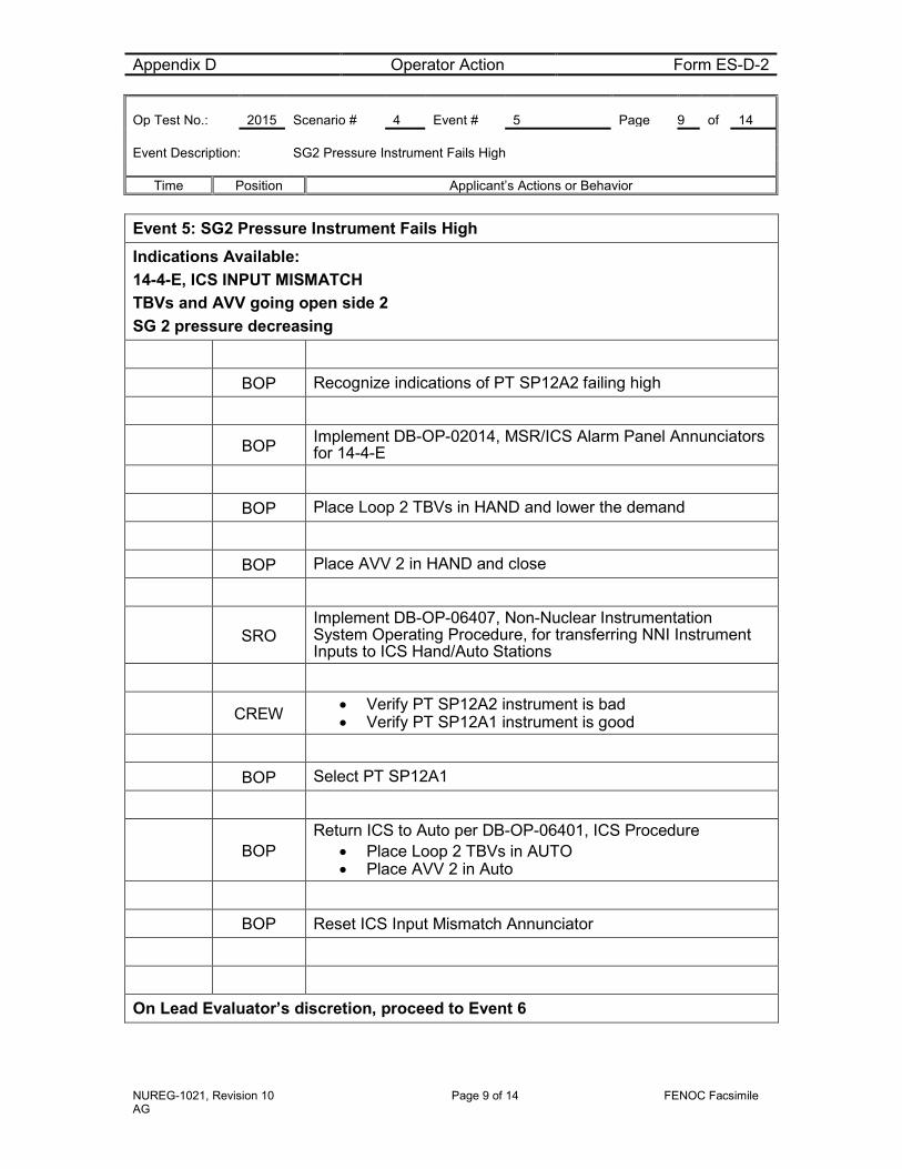
Appendix D Operator Action Form ES-D-2 Op Test No.: 2015 Scenario # 4 Event # 5 Page 9 of 14 Event Description: SG2 Pressure Instrument Fails High
Time Position Applicant’s Actions or Behavior
NUREG-1021, Revision 10 Page 9 of 14 FENOC Facsimile AG
Event 5: SG2 Pressure Instrument Fails High Indications Available: 14-4-E, ICS INPUT MISMATCH TBVs and AVV going open side 2 SG 2 pressure decreasing
BOP Recognize indications of PT SP12A2 failing high
BOP Implement DB-OP-02014, MSR/ICS Alarm Panel Annunciators for 14-4-E
BOP Place Loop 2 TBVs in HAND and lower the demand
BOP Place AVV 2 in HAND and close
SRO Implement DB-OP-06407, Non-Nuclear Instrumentation System Operating Procedure, for transferring NNI Instrument Inputs to ICS Hand/Auto Stations
CREW • Verify PT SP12A2 instrument is bad • Verify PT SP12A1 instrument is good
BOP Select PT SP12A1
BOP Return ICS to Auto per DB-OP-06401, ICS Procedure
• Place Loop 2 TBVs in AUTO • Place AVV 2 in Auto
BOP Reset ICS Input Mismatch Annunciator
On Lead Evaluator’s discretion, proceed to Event 6

Appendix D Operator Action Form ES-D-2 Op Test No.: 2015 Scenario # 4 Event # 6 Page 10 of 14 Event Description: Reactor Coolant System Leak in Containment
Time Position Applicant’s Actions or Behavior
NUREG-1021, Revision 10 Page 10 of 14 FENOC Facsimile AG
Event 6: Reactor Coolant System Leak in Containment Indications Available: Pressurizer Level decreasing Makeup Tank level decreasing CTMT Normal Sump level rising
CREW Recognize indications of an RCS leak in Containment
SRO Implement DB-OP-02522, Small RCS leaks
CREW Recognize immediate action requirements to trip the Reactor with Pressurizer level less than 100 inches
SRO Direct Reactor trip
ATC
Perform DB-OP-02000 Immediate actions • Trip the Reactor • Verify power is decreasing • Trip the Turbine
SRO Implement DB-OP-02000, RPS, SFAS, SFRCS Trip or SG Tube Rupture
SRO/ATC Verify immediate actions
CREW Check for Specific Rules
NOTE RCS Leak becomes a Large LOCA following Reactor trip
Proceed to Event 7 & 8

Appendix D Operator Action Form ES-D-2 Op Test No.: 2015 Scenario # 4 Event # 7 & 8 Page 11 of 14 Event Description: Large LOCA, LPI and CCW Pump failure to start
Time Position Applicant’s Actions or Behavior
NUREG-1021, Revision 10 Page 11 of 14 FENOC Facsimile AG
Event 7: Large LOCA – LPI fails to start 8: CCW Pump failure to start
CREW Recognize a loss of subcooling margin
*Critical Task BOP Implement Specific Rule 2
• *Trip all 4 Reactor Coolant Pumps
BOP Select Incores on Pam panels
*Critical Task BOP
Implement Specific Rule 6 • Start CCW Pump 2
SRO Implement DB-OP-02000 Section 5, Loss of SCM
*Critical Task BOP
Implement Attachment 8, Place MU/HPI/LPI in Service • Start/Verify running both CCW Pumps • Start/Verify running both HPI Pumps • Verify open HP 2A, HP 2B, HP 2C and HP 2D • *Start both LPI Pumps • Transfer MU Pump suctions to the BWST • Set Pressurizer Level Controller to 100 inches • Start/Verify running the second MU Pump • Lock MU Pump suctions on the BWST • Isolate Letdown • Verify Pressurizer heaters are off • Open MU 6421 • Open MU 6419
ATC Control MU\HPI\LPI per specific Rule 3 and Attachment 13
ATC Verify proper SFAS actuation
BOP Verify proper SFRCS actuation
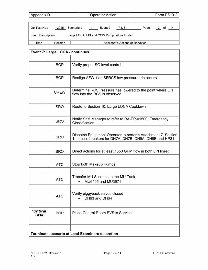
Appendix D Operator Action Form ES-D-2 Op Test No.: 2015 Scenario # 4 Event # 7 & 8 Page 12 of 14 Event Description: Large LOCA, LPI and CCW Pump failure to start
Time Position Applicant’s Actions or Behavior
NUREG-1021, Revision 10 Page 12 of 14 FENOC Facsimile AG
Event 7: Large LOCA - continues
BOP Verify proper SG level control
BOP Realign AFW if an SFRCS low pressure trip occurs
CREW Determine RCS Pressure has lowered to the point where LPI flow into the RCS is observed
SRO Route to Section 10, Large LOCA Cooldown
SRO Notify Shift Manager to refer to RA-EP-01500, Emergency Classification
SRO Dispatch Equipment Operator to perform Attachment 7, Section 1 to close breakers for DH7A, DH7B, DH9A, DH9B and HP31
SRO Direct actions for at least 1350 GPM flow in both LPI lines:
ATC Stop both Makeup Pumps
ATC Transfer MU Suctions to the MU Tank
• MU6405 and MU3971
ATC Verify piggyback valves closed
• DH63 and DH64
*Critical Task BOP Place Control Room EVS is Service
Terminate scenario at Lead Examiners discretion

NUREG-1021, Revision 10 Page 13 of 14 FENOC Facsimile AG
Justification for Critical Tasks
A. Trip all Reactor Coolant Pumps. (CT-1)
When Subcooling Margin is lost all Reactor Coolant Pumps are required to be stopped immediately
B. Initiate Low Pressure Injection (CT-4)
Following the Reactor trip a Large LOCA will develop requiring Low Pressure injection to be placed in service to provide inventory for core recovery as well as long term core cooling. LPI will fail to actuate and will require manual actuation.
C. Implementation of Control Room habitability (CT-27)
During a LOCA event, Control Room Emergency Ventilation is placed in service to aid in controlling radiation levels due to the ingression of airborne fission products
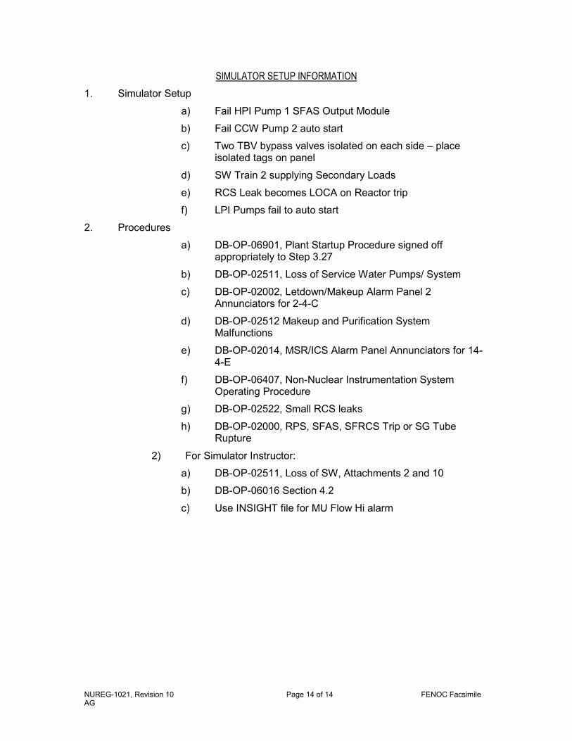
NUREG-1021, Revision 10 Page 14 of 14 FENOC Facsimile AG
SIMULATOR SETUP INFORMATION 1. Simulator Setup
a) Fail HPI Pump 1 SFAS Output Module
b) Fail CCW Pump 2 auto start
c) Two TBV bypass valves isolated on each side – place isolated tags on panel
d) SW Train 2 supplying Secondary Loads
e) RCS Leak becomes LOCA on Reactor trip
f) LPI Pumps fail to auto start
2. Procedures
a) DB-OP-06901, Plant Startup Procedure signed off appropriately to Step 3.27
b) DB-OP-02511, Loss of Service Water Pumps/ System
c) DB-OP-02002, Letdown/Makeup Alarm Panel 2 Annunciators for 2-4-C
d) DB-OP-02512 Makeup and Purification System Malfunctions
e) DB-OP-02014, MSR/ICS Alarm Panel Annunciators for 14-4-E
f) DB-OP-06407, Non-Nuclear Instrumentation System Operating Procedure
g) DB-OP-02522, Small RCS leaks
h) DB-OP-02000, RPS, SFAS, SFRCS Trip or SG Tube Rupture
2) For Simulator Instructor:
a) DB-OP-02511, Loss of SW, Attachments 2 and 10
b) DB-OP-06016 Section 4.2
c) Use INSIGHT file for MU Flow Hi alarm