Appendix D Form ES-D-1 · Appendix D Scenario Outline Form ES-D-1 SCENARIO 1 OVERVIEW The crew will...
56
Appendix D Scenario Outline Form ES-D-1 Facility: Seabrook Scenario No.: 1 Op Test No.: 1 Examiners: Candidates: Initial Conditions: Turnover: Mode 1. Unit at 75% power. IC # 210. The crew will take the shift and commence a rapid downpower to 50% to remove “A” Main Feedwater Pump from service within the next hour. Entered TSASs for CS-P-2B being tagged out of service for planned maintenance 2 hours ago. Return to service expected within 6 hours. 1. Critical Tasks: MANUALLY trip the reactor from the control room when SSPS fails to automatically trip the reactor. [E-0] -. 2. Control the EFW flow rate to not less than 25 GPM per SG in order to minimize the RCS cooldown rate before a severe (orange path) challenge develops to the Malf. No. NIA ptFWPT505 ltRCLT459 mff H002 mfTH002 (severity increases) mfRPSOOl mfRPSOO2 mfMS051 mfRPSO19 mfRPS020 svMSV86 svMsvaa svMSV9O svMSV92 mfS1003 mvFWFV4214A V)ormal, (R)eacti ntegrity CSF Event Type* R (RO) N (6OP/US) I (BOPIUS) TS (US) I (ROIUS) TS (US) C (BOP/US) M (ALL) C (RO/US) C (BOPIUS) ’ECA-2.11 Event Description Rapid power decrease. PT-505 Turbine First Stage Pressure Transmitter Fails LOW Controlling PZR Level Channel LT-459 fails LOW Turbine Generator Vibrations begin to increase. After entry into abnormal operating procedure, turbine vibrations will rapidly increase beyond automatic turbine trip setpoint resulting in a turbine trip. The reactor fails to trip automatically when the turbine trips. The crew will have to trip the reactor manually (CT). ~~~ ~ ___~~ The combination of high turbine vibrations and turbine trip causes a catastrophic rupture of the main steam bottle (down stream of MSIVs). All four MSlVs will fail to close when the MSI signal is actuated. Manual actuation of MSI in the control room should be attempted, but will not cause the MSlVs to close. Upon automatic actuation of Safety Injection from the RCS cooldown, the “A” Safety Injection pump will not automatically start. Procedure progression will be E-0 3 E-2 3 ECA-2.1 where the crew will be directed to reduce feed flow to all SGs to 25 gpm to avoid severe challenge to the Integrity CSF (CT). The motor operator overloads for EFW flow control valve FW- FV-4214A will trip as soon as valve motion is demanded. The operator will be required to utilize FW-FV-4214B to control EFW flow to A SG. y, (I)nstrument, (C)omponent, (M)ajor, (TS)Technical Specification
Transcript of Appendix D Form ES-D-1 · Appendix D Scenario Outline Form ES-D-1 SCENARIO 1 OVERVIEW The crew will...

Appendix D Scenario Outline Form ES-D-1
Facility: Seabrook Scenario No.: 1 Op Test No.: 1
Examiners: Candidates:
Initial Conditions:
Turnover:
Mode 1. Unit at 75% power. IC # 210.
The crew will take the shift and commence a rapid downpower to 50% to remove “A” Main Feedwater Pump from service within the next hour.
Entered TSASs for CS-P-2B being tagged out of service for planned maintenance 2 hours ago. Return to service expected within 6 hours.
1. Critical Tasks: MANUALLY trip the reactor from the control room when SSPS fails to automatically trip the reactor. [E-0]
- .
2. Control the EFW flow rate to not less than 25 GPM per SG in order to minimize the RCS cooldown rate before a severe (orange path) challenge develops to the
Malf. No.
NIA
ptFWPT505
ltRCLT459
m f f H002
mfT H002
(severity increases)
mfRPSOOl
mfRPSOO2
mfMS051
mfRPSO19
mfRPS020
svMSV86
svMsvaa
svMSV9O
svMSV92
mfS1003
mvFWFV4214A
V)ormal, (R)eacti
ntegrity CSF
Event Type*
R (RO) N (6OP/US)
I (BOPIUS)
TS (US)
I (ROIUS)
TS (US)
C (BOP/US)
M (ALL)
C
(RO/US)
C (BOPIUS)
’ECA-2.11
Event Description
Rapid power decrease.
PT-505 Turbine First Stage Pressure Transmitter Fails LOW
Controlling PZR Level Channel LT-459 fails LOW
Turbine Generator Vibrations begin to increase.
After entry into abnormal operating procedure, turbine vibrations will rapidly increase beyond automatic turbine trip setpoint resulting in a turbine trip. The reactor fails to trip automatically when the turbine trips. The crew will have to trip the reactor manually (CT).
~~~ ~ _ _ _ ~ ~
The combination of high turbine vibrations and turbine trip causes a catastrophic rupture of the main steam bottle (down stream of MSIVs). All four MSlVs will fail to close when the MSI signal is actuated. Manual actuation of MSI in the control room should be attempted, but will not cause the MSlVs to close. Upon automatic actuation of Safety Injection from the RCS cooldown, the “A” Safety Injection pump will not automatically start. Procedure progression will be E-0 3 E-2 3 ECA-2.1 where the crew will be directed to reduce feed flow to all SGs to 25 gpm to avoid severe challenge to the Integrity CSF (CT).
The motor operator overloads for EFW flow control valve FW- FV-4214A will trip as soon as valve motion is demanded. The operator will be required to utilize FW-FV-4214B to control EFW flow to A SG.
y, (I)nstrument, (C)omponent, (M)ajor, (TS)Technical Specification

Appendix D Scenario Outline Form ES-D-1
SCENARIO 1 OVERVIEW
The crew will take the shift at 75% with instructions from the SM to reduce power to 50% within the next hour as requested by the dispatcher.
After the crew has the shift (prior to placing rods in manual for the downpower), PT-505 fails low. The crew responds in accordance with OS1 235.05, “Turbine Impulse Pressure PT-505 or PT-506 Instrument Failure”. The failure of this instrument will result in inward rod movement if rod control is in AUTO. The RO should place rod control in manual to halt rod insertion. The crew will BYPASS PT-505 and continue with the downpower with SM permission. The US will address TS in accordance with OS1235.05.
The crew continues‘with the power reduction. After the crew reduces power by 3-4%, or at the lead examiners instruction, the controlling PZR level channel, LT-459, fails low. The crew responds in accordance with OS1 201.07’ “PZR Level Instrument Failure”. Charging flow will increase and letdown will isolate. The RO is expected to take manual control of the PZR level controller and restore PZR level. The RO will also restore letdown to service. The US will address TS in accordance with OS1201.07.
After letdown is restored and PZR level is stabilized, the main turbine will experience vibration problems. The crew responds in accordance with ON1 231.01, “Turbine Generator High Vibration”. After progressing beyond step 1 and at the lead examiners instruction, the turbine vibrations will increase very rapidly beyond the automatic turbine trip setpoint resulting in a Turbine Trip. Since the reactor does not automatically trip, the crew must trip the reactor (CT) and enter E-0, “Reactor Trip or Safety Injection”.
The combination of high turbine vibrations and turbine trip causes a catastrophic rupture of the main steam bottle (down stream of MSIVs). All four MSlVs will fail to close when the MSI signal is actuated. Manual actuation of MSI in the control room will not cause the MSlVs to close. The “ A Safety Injection pump will not automatically start, and should be manually started as part of E-0, Attachment A actions.
Procedure progression will be E-0 3 E-2, “Faulted Steam Generator Isolation” 3 ECA-2.1, ”Uncontrolled Depressurization of All Steam Generators” where the crew will be directed to reduce feed flow to all SGs to 25 gpm (CT) to avoid severe challenge to the Integrity CSF. A component failure will occur as the operator attempts to limit EFW flow to the “A“ S/G. The motor overloads for FW-FV-4214A (Train “A” EFW throttle valve to “ A SIG) will actuate and require the operator to utilize FW-FV-4214B (Train “B” EFW throttle valve to “A” S/G) to limit EFW to SG A to 25 gpm. When feed flow has been reduced, NSO(s) dispatched to the MSlVs will successfully close MSlVs in the west pipe chase (SG A and D). The crew will exit ECA-2.1 returning to E-2. With EFW limited to 25 gpm a RED condition will exist for the HEAT SINK CSF. A note at the beginning of FR-H.l, “Response to Loss of Heat Sink” states that the procedure should NOT be implemented if feed flow was reduced by operator action. The scenario will be terminated at Lead Examiner discretion.

Simulator Operating Exam - Scenario 1
The purpose of scenario one is to observe the crew combat various instrument and component failures as well as a Turbine Vibration problem which progresses beyond automatic turbine trip setpoint that fails to result in a reactorhrbine trip requiring prompt operator action. The scenario will develop into all S/Gs faulted with several complications. The crew takes the watch at 75% power with instructions to commence a rapid downpower maneuver to 50% to remove the “ A MFP from service. Shortly after taking the shift, PT-505 Turbine Impulse Pressure transmitter fails low. This instrument failure will cause rods to insert automatically. The RO is expected to verify plant conditions, stop rod motion, and restore plant conditions to program band. The USshould direct actions in accordance with OS1 235.05, “Turbine Impulse Pressure PT-505 or PT-506 Instrument Failure”.
Event Descr Time
#tion: Position
NOTE
CREW
NOTE
CUE
RO
BOP
us
RO
BOP
BOP
PT-505 TURBINE FIRST STAGE PRESSURE TRANSMITTER FAILS LOW
Applicant’s Actions or Behavior
Shaded items are CRITICAL TASKS.
Commence power decrease in accordance with OS1 000.06, “Power Decrease”. (Figure 6 provides guidance for >I O%/hr rapid downpower) The first event will take place shortly after the crew assumes the watch and prior to any actions to reduce power so that the first event takes place while control rods are in AUTO. After the crew has the watch and on the lead examiner’s cue, PT-505 transmitter fails. This generates a B7457 ROD MOTION DETECTED and a D4421 TAVE-TREF DEVIATION alarm on the VAS. The sound of rods stepping in should be noted by the crew. RO may take manual control of rods as a skill of the operator. He is expected to check that the rod motion is not warranted by high Tave or turbine load reduction first. Checks FW-PI-505 and determines it has failed low and informs US. Enters OS1 235.05, “Turbine Impulse Pressure PT-505 Or PT- 506 Instrument Failure” Places rod control in MANUAL. Manually controls rods or turbine load to restore Tavg to program level. Place steam dump controller to STEAM PRESSURE mode, adjusts steam dump pressure setpoint to 1092 psig and places Steam Dump Controller in AUTO Verifies other plant status items (AMSAC, P-13)
USNRC Examination - Seabrook Station January 2005 Exam Material - Scenario 1
Page 1 of 13

us
NOTE
The crew continues with the power reduction. After the crew reduces power by 3-4%, and when directed by the lead examiner, the controlling PZR level channel, LT-459, fails low. Charging flow will increase and letdown will isolate. The RO is expected to take manual control of the PZR level controller and restore PZR level. The RO will also restore letdown to service.
Verify TS compliance TS 3.3.1 table 3.3-1 item 18.f. Rx Trip System Instrumentation. Action 8: determine by observation of the associated permissive annunciator windows that the interlock is in its required state for the existing plant condition, or apply Specification 3.0.3. Contacts maintenance/l&C about channel failure. Directs I&C to place AMSAC channel in BYPASS. I&C will be called to troubleshoot the failed instrument. The instrument will be put in BYPASS which will remove input to any controVprotection systems. The I&C personnel will also conduct any tripping of bistables called for by Technical SDecification Action Statements.
Event POWER REDUCTION
USNRC Examination - Seabrook Station January 2005 Exam Material - Scenario 1
Descriotion: Time Position
CREW
NOTE
us
RO
BOP
us
us
NOTE
Page 2 of 13
Applicant’s Actions or Behavior After crew completes OS1235.05, SM directs them to continue down power. Allow candidates to demonstrate reactivity control by reducing power by 3-4% (lead examiner’s discretion). During power reduction, RO must maintain AFD within administrative limits. Establishes reactivity management strategy, which should include temperature band, rod control method, AFD band, reactivity plan and load schedule. Refers to ODI-56 values for amount of boric acid to be added.
Calculates load schedule or refers to the schedule provided in
Makes required notifications or requests SM make these notifications. Directs reactivity manipulations and ensures required peer checks occur. Operators are required to remain at the makeup controls during the boration/dilution and makeup evolution. This will ensure proper system response is verified as well as the desired amount.
0 D 1-56.

RO
US/BO P/RO
RO _. .
RO
BOP
BOP
BOP
BOP
BOP
CUE
RO
us
RO
RO
RO
RO
Adds required amount of Boron using OS1008.01, Figure 3 (Boration Checklist). This includes verifying proper system line- up, Placing Blender Mode Start Switch to STOP. Placing Boric Acid Blender Mode Selector Switch to BORATE, selecting desired flow rate and quantity, Placing Blender Mode Start Switch to START, verifying proper plant response, and resetting the control system to AUTO when desired amount of acid is added. Peer checks will be provided for all reactivity manipulations. Because of a three man crew, this peer check can be provided by the US. As directed by US, if RCS boron concentration is being changed by greater than 50 ppm, OPERATE pressurizer heaters to force spray to equalize boron concentration between the RCS and pressurizer. RO will manually insedwithdraw rods to maintain axial flux difference in band. Use the LOAD SELECTOR load decrease push-button or LOAD LIMIT SET potentiometer to reduce load to the desired load. If reducing load with the load selector, FOLLOW the load set with the load limit set potentiometer and the standby load set. Maintain generator VARs consistent with load per The Turbine Generator Capability Curve and load dispatcher’s instructions. Maintain the manual voltage regulator nulled.
Maintain speed deviations for both main feed pumps nulled.
FAILURE OF CONTROLLING PZR LEVEL INSTRUMENT
VAS D4461 PZR LVL LOW & HTR INTERLOCK ACTUATED & F4324/F4325 PZR GROUP C/D BACKUP HTR TRIPPED & F4323 PZR CONTROL HEATERS TRIPPED annunciators are received. Also Ll-459 indication fails low. Recognizes controlling channel (Ll-459) has failed low. Recognizes letdown has isolated. Informs US. Enters and directs action IAW OS1201.07, “PZR Level Instrument Failure”. Takes manual control of PZR level controller RC-LK-459 or controls level with letdown and charging flow. Selects an alternate level channel for CONTROL/BACKUP as necessary. Selects an alternate RECORDER channel. Resets the control group of PZR heaters.
Determines that letdown can be restored and restores letdown IAW OS1201.07.
USNRC Examination - Seabrook Station January 2005 Exam Material - Scenario 1
Page 3 of 13

I RO 1 Establish normal letdown: VERIFIES CC-V341 OPEN.
NOTE
VERIFIES CS-TK-130 in AUTO, CLOSE CS-HCV-189, CLOSE CS-HCV-190, OPEN RC-LCV-459, OPEN CS-VI 45, establish letdown flow using letdown flow control valves. OS1 002.08, “PZR Level Control System Operations” may be
RO referenced to restore system to AUTO. Returns PZR level controller to AUTO after proper controller
us
NOTE-
setpoint and proper PZR level are established. Verifies TS compliance 3.3.1 table 3.3-1 item 11 and TS 3.3.3.6, item 5, Accident Monitoring Instrumentation. Verifies redundant channel bistables NOT tripped and inform I&C of control le r fa i I u re. Table 3-3.1 item 1 I : inoperable channel LT-459 tripped within
When directed by the lead examiner, the main turbine generator vibrations will begin to increase to about 8-10 mils requiring entry into ONI231.01, “Turbine High Vibrations”. Once into the abnormal and beyond step 1, Turbine Vibrations will rapidly increase beyond the turbine trip setpoint causing an automatic turbine trip. However, the reactor will fail to trip, requiring a manual reactor trip (CT). Immediately following reactor trip, a catastrophic failure of the MS Bottle downstream of MSlVs will occur. MSlV will not be able to close until much later in the scenario when NSO’s locally close the “A’ and ‘ID” MISV’s from the west pipe chase. Other complications will occur as follows:
NOTE 6 hours. TS 3.3.3.6 item 5: requires that LT-459 be returned to operable
Time
us status within 7 days. Informs I & C of failed channel and requests assistance with troubleshooting including placing LT-459 in bypass (if desired by lead examiner)
USNRC Examination - Seabrook Station January 2005 Exam Material - Scenario 1
Event Description:
Page 4 of 13
MAIN GENERATOR VIBRATIONS / AUTO TURBINE TRIP w/o AUTO REACTOR TRIP LEADING TO ALL S/G’S
Position CUE
CUE
FAULTED WITH INABILITY TO ISOLATE FAULT FROM CONTROL ROOM WITH OTHER COMPLICATIONS
Applicant’s Actions or Behavior After the US discusses TS requirements for the failure of controlling PZR level instrument, and at the discretion of the lead examiner, the main turbine generator vibrations will begin to increase as noted by VAS B5933 TURB GEN BRG 7 VIBRATION HIGH & 65935 TURB GEN BRG 8 VIBRATION HIGH. After the crew has progressed beyond step 1 of ON1231 -01, “Turbine Generator High Vibration”, the Turbine will AUTO trip as noted by RED Hardwire ANNUCIATOR on UA-52, “TURBINE TRIP”, White Hardwire on UA-53, TURBINE TRIP”, and numerous vibration alarms are received on VAS.

I
NOTE
BOP
us BOP/US
BOP
BOP/US -..
BOP/US
CUE
ROlUS
us RO
BOP
RO/B 0 P/ us
RO
BOP
If the crew is conservative and decides to trip the reactorhurbine based on high vibrations increasing quickly, then it is important that we increase severity before they trip in order to preserve critical tasks. Acknowledges alarms for high turbine vibrations and pulls up MPCS graphics to monitor bearing vibration. Directs entry into ON1231.01, “High Turbine Vibration”.
Monitors vibrations less than trip limits. Determines that Bearing 7 & 8 are limiting at about 10 mils. (alarm is at 8 mils) Checks Main Generator breaker closed.
Directs turbine load adjusted until vibration levels are less than values needed to support extended operations. May get Engineering involved. Checks Turbine vibrations stable or increasing. (vibrations will remain stable until lead examiner requests the severity increased) After trip and insertion of Main Steam Bottle rupture, the crew will hear the noise generator simulating main steam noise from steamline break until S/G’s are blown down. Recognizes the reactor did NOT trip and MANUALLY trips the Reactor (CT). Enters E-0, “Reactor Trip or Safety Injection”
Immediate actions: Verifies reactor trip and bypass breakers open, neutron flux decreasing, and rod bottom lights lit. Checks . - if SI is actuated, verifies botktrains of SI actuated. Immediate actions: Verifies all turbine stop valves closed and generator breaker open, Verifies power to AC Emergency busses, verifies all emergency busses energized. Performs ESF Actuation Verification per Attachment A of E-0. Notes “A” SI Pump did not start and manually starts the “A” SI pump. Informs the US that the “ A SI pump did not start but was manually started. Also as part of this attachment Main Steamline isolation is checked. It should be noted all S/G pressures are less than 585 psig, that MSIV’s did not close, manual attempt failed and the status should be reported to the us Checks containment pressure has remained less than 18 psig by pressure recorder. Verify Total EFW Flow - Greater than 500 GPM.
USNRC Examination - Seabrook Station January 2005 Exam Material - Scenario 1
Page 5 of 13

RO/BOP
BOP
BOP/US
RO
RO
BOP
us
BOP/US
BOP/US
NOTE
us
NOTE
BOP
BOP
BOP
BOP
BOP
Monitor RCS temperature - Stable At or Trending to 557F. RCS will be cooling down due to rupture of MS bottle and MSlVs failing to close. Stop dumping steam to condenser and atmosphere. OPEN EFW min-flow valves AND throttle total feed flow to maintain greater than 500 gpm. If cooldown continues, close MSIVs, MSlV bypasses and upstream drains. MSD-V44 & 45 must be closed on rear of MCB. Identifies FW-FV-4214A did not close when attempts are made to throttle EFW. Should throttle FW-FV-4214B to reduce EFW flow. NSO’s should be sent to locally close MSIV’s when it is recognized that MSIV’s cannot be closed from MCB. Check RCS isolated. Verify letdown isolated. Verify PORVs closed. Verify normal Spray valves closed. Check if RCPs should be stopped. Reports adequate subcooling exists such that RCPs do not need to be secured. Check if SG Pressure Boundary is Faulted. All S/G pressures are decreasing in an uncontrolled manner or may be completely depressurized. Directs transition to E-2, “Faulted Steam Generator” based on S/G ‘A’ depressurization. Check Main Steam Isolation. Manually closes MSlVs from MCB and directs local closure (may have been previously pe rfo r med ) Checks if SG pressure boundary is intact. Notes all S/Gs are decreasing in an uncontrolled manner or completely depressurized at this time. If S/G boils dry, the BOP may adjust ASDV setpoints to stabilize RCS temperature as directed by Operator Action Summary page of E-2. Directs transition to ECA-2.1, “Uncontrolled Depressurization of All S/G’s” US may address the RED HEAT SINK CSF. He should note the caution in FR-H.1 prior to step I and not perform FR-H.1. A caution in ECA-2.1 also states that FR-H.l should not be implemented unless 500 gpm is not available. Check Secondary Pressure boundary. Manually closes MSlVs from MCB and directs local closure (should have been previously performed) Check S/G ASDVs closed.
Checks FWRV and FWRV bypasses closed.
Checks FW IVs closed.
Checks MDEFW or SUFP feedwater to supplying S/Gs
USNRC Examination - Seabrook Station January 2005 Exam Material - Scenario 1
Page 6 of 13

BOP ~
RO/BOP
RO
BOP/US
BOP
RO
RO
RO -.
RO/BOP
RO
RO
RO
RO
RO
CUE
NOTE
Closes MS-393 and MS-394.
Checks S/G Blowdown valves SB-9, I O , 11, 12 closed.
Control feed flow to minimize RCS cooldown. Check cooldown rate in RCS less than 100 F/hr. Open EFW pump mini-flow valves and decrease feed flow to not less than 25 aDm to each S/G (CT) Checks narrow range S/G levels less than 50%.
Check RCS hot leg temperatures stable or decreasing.
Checks if RCPs should be stopped. ~
Checks PZR PORV and Block Valves.
Checks secondary radiation.
Checks if RHR pumps should be stopped.With RCS pressure greater than 260 psig, reset SI and stop RHR pumps placing them in standby. Checks if Containment Spray should be stopped. Should not be running. Check RWST level greater than 11 5,000 gallons.
Check if SI Accumulators should be isolated. If at least two RCS hot leg temperatures are < 370 F than energize MCC- E522 and E622 and isolate accumulators, then de-energize MCC-E522 and E622. Check if ECCS flow should be reduced. Action taken in this step will determine course of action. If RCS pressure is still decreasing the procedure will loop the operator back to step 2. If RCS pressure is increasing and PZR is > 5%, then SI will be reset. Lead examiner may terminate scenario at any point in ECA-2.1 or if desired to upon transition back to E-2. IF desired to transistion back to E-2, it will be reported at this time that “A” & “D” MSlVs have been successfullv locallv closed. Upon completion of follow-up questioning, the SRO will perform JPM LOIT08 (Post EAL Determination and Event Classification) They should declare a UE based on EAL-15b It is also possible they may declare a SAE based on the red path which exists on HEAT SINK due to throttling in ECA-2.1 which is acceptable. This will be determined by the staff based on the endpoint of the scenario.
USNRC Examination - Seabrodc Station January 2005 Exam Material - Scenario 1
Page 7 of 13

Simulator Instructor Instructions for Scenario 1
0 0 0
Please track the following parameters in addition to the standard set (if any):
mfRPSOOl AUTOMATIC REACTOR TRIP FAILURE (TRAIN ‘A’) mfRPS002 AUTOMATIC REACTOR TRIP FAILURE (TRAIN ‘B’) mfRPSO19 MS ISOLATION FAILS TO AUTO ACTUATE (TRAIN ‘A’) mfRPS020 MS ISOLATION FAILS TO AUTO ACTUATE (TRAIN ‘B’)
1.
0 0 0
0
0
. mfS1003 SI Pump P-6A FAILS TO AUTO START svMSV86 IS0 VALVE FAILS OPEN svMSV88 IS0 VALVE FAILS OPEN svMSV9O IS0 VALVE FAILS OPEN svMSV92 IS0 VALVE FAILS OPEN
Initialize the simulator at IC #210, 75% power. (This IC is password protected for NRC security reasons. Password can be obtained from Ian Forbes or Len Hubbard ONLY) --.
2. I Protected train is ‘A’. I 3. 0
0 0
Ensure or place the control switch for CS-P-2B in PTL Ensure CS-V-197 is CLOSED with power removed. Danger tag CS-P-2B and CS-VI97 Ensure the pushbutton control switch for CVCS TRAIN B BYPANOP light is illuminated.
0 0
mvCSV197, MOV BREAKER STATUS OPEN bkCSl P2B BREAKER RACKED-OUT
USNRC Examination - Seabrook Station January 2005 Exam Material - Scenario 1
Page 8 of 13

Perform immediately after simulator is in RUN:
0 0 0
0 0 0 0 0
~~~ ~ ~~~
ENSURE simulator is stabilized and alarms are cleared. Run SlMHlST ENSURE applicable items on Simulator Setup Checklist (NT-5701-6) are com pleted SELECT: MF List -SELECT: Feedwater (component) SELECT: mvFWFV4214A SELECT: FAILS OPEN INSERT
Ensure the following Procedures are Available:
0 0 0 0
OS1000.06, Opened to Figure 6 for Downpower per Turnover OS1235.05 OS1201.07 ON1231.01
0 0 0
USNRC Examination - Seabrook StaEon January 2005 Exam Material - Scenario 1
E-0 E-2 ECA-2.1
Page 9 of 13

Shortly after the crew assumes the watch and only after lead examiner's cue:
PT-505 Failure.
0
0 0 0
SELECT: MF List SELECT: Feedwater (component) SELECT: ptFWPT505 SELECT: Fail LOW SELECT: INSERT
The crew will contact I&C to respond to PT-505. Simulator operator will play role of I&C. Whendirected by crew, bypass PT-505. If the crew does not make a decision on bypass/trip status, call in as SM and direct BYPASS of PT-505.
0 0 0
To select operator bypass for PT-505:
SELECT: Panel Overview SELECT: AMSAC CP-519 SELECT: Switch SW12 to TPIMP (P505)
0 0
0 0
Crew continues power reduction.
SELECT: MF List SELECT: Reactor Coolant (component) SELECT: ltRCLT459 SELECT: Fail LOW SELECT: INSERT
When directed by lead examiner:
0 0 0 0 0
Fail Controlling PZR Level Transmitter.
SELECT: Panel Overview SELECT: BTI CP1 SELECT: CP1 Door Open SELECT: The NORM/ENABLE switch to ENABLE SELECT: LB-459A (High Level Channel Trip) to BYPASS
If I&C is directed to bypass LT-459:
To select operator bypass for LT-459:
USNRC Examination - Seabrook Station January 2005 Exam Material - Scenario 1
Page 10 of 13

When directed by lead examiner:
Main Turbine Generator Vibrations Increase:
0
0 0 0 0 0 0
SELECT: malfunctions at top of page SELECT: mffH002 ENTER: 0 (seconds) into ramp time ENTER: 18 (mils) into final value SELECT: MODIFY
SELECT: MF List SELECT: Turbine Generator SELECT: mfT H002 ENTER: 300 (seconds) into ramp time ENTER: 6 (mils) into final value
-SELECT: INSERT
0 0
0
As soon as the crew has entered ON1231.01, “Turbine High Vibrations” and progressed beyond step 1 at lead examiners discretion, increase turbine vibrations beyond the automatic turbine trip setpoint. (THIS MUST OCCUR BEFORE CREW DECIDES TO TRIP REACTORflURBlNE)
SELECT: malfunctions at top of page SELECT: mfTH002 ENTER: 200 (seconds) into ramp time ENTER: 0 (mils) into final value SELECT: MODIFY
0 0 0 0 0
Post trip ramp the turbine vibrations down to 0 over 200 seconds.
SELECT: MF List SELECT: Main Steam SELECT: mfMSO51 SELECT: Final Value of 1 (no time delay or ramp) SELECT: INSERT
AS SOON AS REACTOR IS TRIPPED insert a catastrophic rupture of the Main Steam Bottle (downstream of the MSIVs).
USNRC Examination - Seabrook Station January 2005 Exam Material - Scenario 1
Page 11 of 13

Security will call the Control Room and inform them that there are massive quantities of steam on the south end of the Turbine Building.
0 0
0
Previously, Auto and Manual MSI and Auto MSIV closure malfunctions (previously inserted) will cause all S/Gs to blowdown. Once the crew has reduced EFW flow to about 25 gpm per S/G (CT) in ECA-2.1, NSO’s who have been dispatched to locally close MSIV’s will be successful in the West Pipe Chase closing the “A” and “D” MSIV’s (if desired by lead examiner)
SELECT: COMPONENT MF at top of page CLICK ON: svMSV86 IS0 VALVE FAILS OPEN CLICK ON: svMSV92 IS0 VALVE FAILS OPEN SELECT : DELETE MF
USNRC Examination - Seabrook Station January 2005 Exam Material - Scenario 1
Page 12 of 13
Briefing Sheet/Turnover Information for Scenario 1
Protected Train is A
MODE 1 : 75% RTP, CBD @ 180 steps (ARO = 230 steps), Boron Concentration = 939 ppm. ODI-56 Values for MOL Core I O on US desk, + I degrees = 170 gal RMW, -1 degree change = 27 gal BA; AFD target - 1.39. “C” and “D” Backup Heaters are ON.
_ _ _ The Shift Manager has provided instructions to reduce power to 50% within the next hour to remove “A’ Main Feedwater Pump from service. Figure 6 of OS1 000.06 will be used as guidance for this downpower. ODI-56 values for 25%/HOUR to 18% MainTurbine Shutdown Values should be used.
Centrifugal Charging Pump CS-P-2B is danger tagged out for planned maintenance. Entered TR 3.1.2.2 and TSAS 3.5.2.a two hours prior to turnover. Expected return to service is 6 hours after turnover.
USNRC Examination - Seabrook Station January 2005 Exam Material - Scenario 1
Page 13 of 13

Facility: Seabrook Scenario No.: 2 Op Test No.: 2
Examiners: Candidates:
Initial Conditions:
Turnover:
Mode 2. Unit is operating at
The crew will take the shift and commence a power increase up to but not to exceed 3% power.
The “C” Primary Component Water pump is tagged out for bearing replacement. The motor experienced high vibrations during quarterly surveillance.
Seismic Event occurred two shifts ago.
amps , MOL. IC# 21 1
Critical Tasks: 1, MANUALLY actuate at least one train of Containment Spray or start one train of Containment Spray Building Equipment prior to step 7 of E-0 following Large Break LOCA. [E-0]
2. PERFORM TRANSFER to cold leg recirculation when automatic swapover occurs
Malf. No.
NIA
ltFW LT529
ptRCPT455
Event
1
2
3
4
5
mfRC024A
mfCBS004
mfCBSOO5
mfFCS002
mfFW039
svMSlV395
bkFWP37B
NIA
(R)eacti’
Ir 115,000 9 Event Type’
R (RO) N (BOPIUS)
TS (US)
I (BOPIUS)
TS (US)
I
(ROWS)
TS (US)
M (ALL)
C (ROIUS)
C
(RO) C
(BOP)
VIA
ons in the RWST, whichever occurs first. [ES-1.31
Event Description
Raise reactor power from I O “ amps to approximately 3% power.
Place Electric EFW Pump (P-37B) in PTL after SM informs crew that it is reported to be inoperable and address TS.
FW-LT-529 Fails LOW causing the “B” Feedwater Regulating Bypass valve to fail open.
Controlling PZR pressure channel fails HIGH.
Large Break LOCA occurs leading to automatic reactor trip with failure of Containment Spray pumps to automatically start upon Phase “B” actuation. The crew will have to manually start at least one Containment Spray pump (CT). Upon completion of immediate actions, all RCPs should be tripped based on E-0 Operator Action Summary. The “B” CCP pump will not automatically start, and should be manually started as part of E-0, Attachment A actions. The SUFP will trip after reactor trip and MS-V395 will close after the Steam Driven EFW Pump Auto Starts, causing it to shutdown. It should be recognized by the BOP that there is no EFW flow. Procedure progression will be E-0 to E-1 to FR-P.l (Red) to FR-Z.l (Orange) to E-1 to ES-1.3.
Perform transfer to cold leg recirculation per ES-1.3 when the automatic swapover occurs or 115,000 gallons in the RWST, whichever occurs first. (CT)
y, (I)nstrument, (C)omponent, (M)ajor, (TS)Technical Specification

SCENARIO 2 OVERVIEW
The crew will take the watch at I O 4 amps on the intermediate range channels. The “C” PCCW Pump is tagged out for maintenance. The crew is instructed to continue a power increase in accordance with OS1 000.07, “Approach to Criticality” and OS1 000.02, “Plant Startup from Hot Standby to Minimum Lo ad ” .
After the crew assumes the watch, they will continue power ascension in accordance with OS1 000.07, “Approach to Criticality”. Once the lead examiner is satisfied with the reactivity addition, the SM will inform the US that Engineering has determined the Electric EFW Pump to be inoperable. The US should direct P-37A placed in PTL and address TS. He should recognize that a Mode change is not allowed based on these plant conditions.
Once the US has evaluated TS for EFW pump condition and at lead examiners discretion, the “B” S/G level transmitter, LT-529, fails LOW. The crew should respond to the failure in accordance with OS1253.03. The high input to the feed control system will cause “B” S/G feed regulating bypass valves to modulate OPEN, increasing feed flow to “B” S/G. There is no redundant channel for this level transmitter thus the BOP operator must maintain manual control of S/G “B” feed regulating bypass valve for the remainder of the startup. The US will verify TS compliance at the discretion of the lead examiner during or following the scenario.
After the US verifies TS compliance or at the lead examiners discretion, the controlling PZR pressure instrument fails high. PZR spray initiates and RCS pressure will decrease rapidly. It is expected that the RO will identify the failed channel and take manual control of the master pressure controller, stabilizing RCS pressure. TS assessment is can be performed during the scenario or immediately following at the Lead Examiners discretion. If the crew is not timely, the plant may trip on low pressure safety injection (low pressure trip blocked by P-7/P-10) which will not adversely affect the scenario. Whether the crew manually trips the reactor or the reactor automatically trips, A Large Break LOCA will occur with a failure of both containment spray pumps to automatically start. It is a critical task that the crew manually starts at least one containment spray pump prior to step 7 of E-0 (CT).
.
Following E-0, “Reactor Trip or Safety Injection” immediate actions, the RCPs should be tripped based on E-0 Operator Action Summary required actions. It should be recognized that the “B” CCP did not start and the pump should be manually started during E-0 Attachment A actions. The BOP should recognize the SUFP tripped and the Steam Driven EFW PUMP started but MS-V395 closed and P-37A secured post reactor trip, therefore no EFW flow exists. (Electric EFW Pump P-37B previously placed in PTL). Note that at this low power, there is still adequate S/G inventory and S/G heat sink is not an issue during large break LOCA.
Procedure progression following reactor trip is E-0 to E-I , “Loss of Reactor or Secondary Coolant” to FR-P.1, “Response to Imminent Pressurized Thermal Shock Conditions” (RED) to FR-Z.1, “Response to High Containment Pressure” (ORANGE) to E-I and to ES-1.3, “Transfer to Cold Leg Recirculation”. Note that transitions to FR-P.l and FR-Z.l are dependant upon whether plant conditions are met which differ during a low power scenario based on crew progression through procedures. Note that within three minutes of receiving the RWST Lo-Lo level alarm the first three steps of ES-1.3 must be performed. It is a critical task that at least one train of cold leg recirculation be established (CT). Note also that because this is a low power scenario, it is possible depending on how expeditious the crew is to start containment spray, that FRP entry conditions may NOT be met (ie: RCS temperature does may not drop low enough or containment pressure does not remain high enough).

Simulator Operating Exam - Scenario 2
The purpose of scenario two is to observe the crew combat various instrument and component failures during low power plant conditions following a power increase and TS issue which surfaces related to an EFW pump (P-376) reported to be inoperable. The scenario will develop into a Large Break LOCA with complications requiring the crew to deal with several FRPs. The crew takes the watch with instructions to continue a power increase from 1 0-8 amps to 3%. “C” PCCW is danger tagged for maintenance. The SIG “6” level transmitter, LT-529, fails LOW resulting in S/G “B” feed regulating bypass valves modulating open, increasing feed to S/G “B”.
_. - Event Descr Time
Ition: Posit ion
NOTE
CREW
NOTE
NOTE
RO
RO
CUE
us BOP
POWER ASCENSION/ TS ISSUE & S/G “B” LEVEL TRANSMITTER FAILS LOW
Applicant’s Actions or Behavior
Shaded items are CRITICAL TASKS.
POWER ASCENSION
Crew assumes the watch and continues with power ascension on step 4.7 of OS1200.07, “Approach to Criticality” then starts OS1200.02, “Plant Startup from Hot Standby to Minimum Loading”. A reactivity brief should occur. Step 4.7.1 of OS1200.07: The reactor is critical and power is being maintained at approximately intermediate range. To continue plant startup to minimum load, refer to OS1000.02. Caution: Do not exceed the capacity of the startup feed pump (191 amps or 3% RTP). Do NOT exceed a STABLE start up
amps in the
rate of 1 DPM. Increase reactor power to between 1% and 3% by soluble boron control or control rod motion, and maintain TAVG greater than or equal to TREF and within the limits of Figure 2, TAVG Proaram. RO will have manual control of control rods and withdraw rods at a rate determined by US. TECHNICAL SPECIFICATION ISSUE (P-37B)
Once the reactivity manipulation is completed satisfactorily and with lead examiner concurrence, the SM will report that the Electric EFW Pump has been reported by Engineering to be inoperable. Directs BOP to place P-37B in PTL.
Places P-37B in PTL, acknowledges alarm and reports the same.
USNRC Examination - Seabrook Station January 2005 Exam Material - Scenario 2
Page 1 of 11

u s
CUE
BOP --.
us
BOP
BOP
us
NOTE
us
Addresses TS for the reported condition. Enters TSAS 3.7.1.2a and TS 3.0.4. Recognizes a mode change cannot occur. SIG “B” LEVEL TRANSMITTER FAILS LOW
Once the EFW issue has been evaluated by the NRC team, the lead examiner will direct the failure of the “B” S/G level transmitter, LT-529, to it’s LOW value. The low S/G level will cause “B” S/G feed regulating bypass valve to modulate open and “B” S/G water level to increase. VAS F4840 S/G B LEVEL
are received. Informs US of increasing S/G water level in “B” S/G. The BOP will verify level deviation on controlling level channel, FW-LI- 529. The BOP will take manual control of S/G “B” feed regulating bypass valve and restore S/G “B” water level to the program level. The US will enter and direct action from OS1235.03, “S/G
LO-LO, D4877, S/G B LEVEL LO, & D4771, S/G B LVL DEV
Level Instrument Failure”. Check S/G Water Level Control, identify failed instrument.
Control S/G water level manually between 50-70% on the narrow range level detectors. Verifjl redundant bistables NOT tripped. Verify Technical Specification Compliance, TS 3.3.1 table 3.3-1 item 13 Reactor Trip System Instrumentation, TS 3.3.2 table 3.3-3, items 5.b, 6.a, 7.c, and 1O.c Engineered Safety Features Actuation System Instruments, TS 3.3.3.6 table 3.3-10, item 7 Accident Monitoring Instruments. TS Actions required: For 3.3.1 and 3.3.2: startup and/or power operation may proceed provided the inoperable channel is placed in the tripped condition within 6 hours and the minimum channels OPERABLE requirement is met. The channel may be bypassed up to 4 hours for surveillance of other channels. For 3.3.3.6: requires LT-529 to be returned to OPERABLE status within 48 hours per action b. Notifies I&C of level channel failure and directs them to come to the control room.
USNRC Examination - Seabrook Station January 2005 Exam Material - Scenario 2
Page 2 of I 1

When directed by the lead examiner, the controlling PZR pressure channel, PT- 455, fails high, causing the spray valves to open and RCS pressure to rapidly decrease. The RO is expected to take manual control of the PZR pressure controller and restore RCS pressure to NOP.
Event Descr Time
ition: Position CUE
u s -.
RO
RO
RO
RO
RO
RO
RO
RO
US/RO
NOTE
us
PZR PRESSURE INSTRUMENT PT-455 FAILURE
Applicant’s Actions or Behavior At lead examiner’s cue, the controlling channel of PZR pressure fails high. VAS F7860 PZR PRESS HI CHANNEL TRIP is received. Also a white light on UL-6 for Hi Press P- 455A illuminates. Enters and directs actions of OS1201.06, “PZR Pressure I n s t ru rn e n t/C o m po n en t Fa i I u re” Checks PORVs closed.
Check Normal PZR Spray valves Closed. With PZR pressure 4 2 6 0 psig, the RO may take manual control of spray valves and close them. This should stop RCS pressure drop and avoid reactor trip. Determines that PT-455 has failed high.
Takes manual control of master PZR pressure controller or heaters and spray and restores normal pressure. (This step may have been already been performed as a Skill of the Operator action prior to reading procedural step due to the rapid impact on the plant) Selects an alternate pressure channel for CO NTROL/B ACKU P , as necessary . Selects an alternate pressure channel recorder as necessary.
Selects an alternate delta T, Overtemperature and Over pressure channel for recorder as necessary. Once RCS pressure is restored to normal than align pressure control to auto. Verify Redundant Channel Bistables NOT TRIPPED and Verify Technical Specification Compliance: TS 3.3.1 table 3.3-1, items 7,9, and 10 Reactor Trip System Instrumentation. TS 3.3.2 table 3.3-3 items 1 .d and 1O.a ESFAS Instrumentation. TS 3.2.5 DNB Parameters (if pressure drops below 2185psig). Ensures I&C is informed. TS 3.2.5: with pressure below 2185 psig, restore pressure to its normal limits within 2 hours or reduce thermal power to less than 5% RTP within the next 4 hours. Informs I & C of failed channel and requests assistance with troubleshooting including placing PT-455 in bypass (if desired by lead examiner)
JSNRC Examination - Seabrook Station January 2005 Ixam Material - Scenario 2
Page3of 11

When directed by the lead examiner, INSERT Large break LOCA. The failure of Spray pumps to AUTO start is dormant. Following Reactor Trip, INSERT the trip of the SUFP and MS-V395 closure.
Event Description :
Time Position CUE
us --.
RO
BOP
RO/U S
RO/B 0 P/ us
RO
BOP
RO/BOP
LARGE BREAK LOCA with FAILURE OF CONTAINMENT SPRAY PUMPS TO AUTO START and OTHER
COMPLICATIONS Applicant’s Actions or Behavior
After the US discusses TS requirements for the failure of controlling PZR pressure instrument, and at the discretion of the lead examiner, a Large Break LOCA will be inserted which leads to an automatic reactor and turbine trip. Enters E-0, “Reactor Trip or Safety Injection”
Immediate actions: Verifies reactor trip and bypass breakers open, neutron flux decreasing, and rod bottom lights lit. Checks if SI is actuated, verifies both trains of SI actuated. Immediate actions: Verifies all turbine stop valves closed and generator breaker open, Verifies power to AC Emergency busses, verifies all emergency busses energized. Upon completibn of immediate actions, it should be recognized that with no subcooling and SI or CCPs running that RCP’s should be tripped based on Operator Action Summary for E-0. Performs ESF Actuation Verification per Attachment A of E-0. Notes “B” CCP Pump did not start and manually starts the “B” CCP pump. Informs the US that the “B” CCP pump did not start but was manuallv started. Checks containment pressure has remained less than 18 psig by pressure recorder. Recognizes that NOT all Phase B status lights are lit, actuates both CBS/CVI manual actuation switches and manually starts at least one containment spray pump. (CT) Verify Total EFW Flow - Greater than 500 GPM. EFW pumps will have started due to the SI. Because of the low power scenario there will be more than sufficient inventory in the S/G’s. The BOP should recognize the SUFP did not start and inform US. Monitor RCS temperature - Stable at or Trending to 557F. RCS will be cooling down due to SI flow. Stop dumping steam to condenser and atmosphere. OPEN EFW min-flow valves AND throttle total feed flow to maintain greater than 500 gpm. When SG level is adequate based on 65% wide range in at least two S/Gs or 5% narrow range in at least one S/G (25% narrow range in at least one S/G if adverse), then throttle feed flow to restore S/G level between 25% and 50% narrow range. If cooldown continues, close MSIVs, MSlV bypasses and upstream drains.
USNRC Examination - Seabrook Station January 2005 Exam Material - Scenario 2
Page 4 of 11

I
RO
RO
BOPIUS
RO/BOP/ us - -
RO/BOPI us
us
RO
Note
RO/BOP/ us
RO/BOP/ us
BOP
NOTE
BOPIROI us
Check RCS isolated. Verify letdown isolated. Verify PORVs closed. Verify normal Spray valves closed. Check if RCPs should be stopped. Should have been previously secured by OAS, however, if not they will be secured in this step. Check if SG Pressure Boundary is Faulted. Note: The crew could transition into E-2 based on lower pressure in “A” and “B” SIG due to a combination of steam flow to Steam Driven AFW pump being supplied from these two S/Gs and low power scenario. If this is the case they will perform E-2 actions and then transition to E-1 . Check if SG U-tubes are intact.
Check if RCS is intact. Recognizes containment pressure/radiation level and containment building level are abnormal. Directs transition to E-I, “Loss of Reactor or Secondary Coolant”. Check if RCPs should be stopped. (should already have been stopped) Upon first transition out of E-0, CSF Status Trees should be verified. Based on how far the RCS cools down, will determine whether or not an orange or red path will exist for FR-P.1. Also depending on how fast the operators are to start Containment Spray pumps and process through EOPs will determine how high containment pressure is and therefore whether an orange path exists for FR-Z. 1, Actions for possible FRP entry are outlined below: If a red or orange path exists for FR-P.l at any time during this scenario, the crew will transition to this procedure, check RCS pressure is c 260 psig and return to procedure step in effect since PTS is not a concern. If an orange path exists for FR-Z.l due to high containment pressure, the crew will transition to this procedure, Verify Containment Isolation Phase A, check if containment spray is required, verify at least one containment enclosure fan is running, verify MSIVs, bypasses and upstream drains isolated, check if feed flow should be isolated to any SG, Check hydrogen concentration and exit this procedure to return to procedure and step in effect. Checks if SG pressure boundary is faulted.
Check intact SIG levels. Should have adequate inventory.
Checks secondary radiation and determines no transition to E- 3 is necessary.
USNRC Examination - Seabrmk Station January 2005 Exam Malerial - Scenario 2
Page5of11

RO
RO/US
RO
RO
RO/BOP
- -
BOP
RO/US
RO
ROWS
NOTE
~
RO/BOP/ us
us RO/US
RO
RO
RO
BOP
Check PZR PORV and Block Valves.
Check if ECCS flow should be reduced. Based on insufficient subcooling, the US will proceed to step 7. Check if containment spray pumps should be stopped. If containment pressure has dropped below 4 psig than reset Phase B isolation and containment spray signals, stop CBS pumps and place in standby. Check if RHR pumps should be stopped. Determine RCS pressure is < 260 psig and do not stop RHR pumps. Check RCS and SG Pressure. If SG pressure is NOT stable or NOT INCREASING OR RCS Pressure is NOT stable or NOT DECREASING than the crew will loop back to Step 1 of E-I until these conditions are met. If and when they are met continue with following steps. Check if EDG should be stopped. Reset SI, verify all AC busses energized by offsite power from UATs or RATS, stop and unload EDG by depressing both emergency stop pushbuttons, after EDG stopped, reset for auto start and isolate SW to EDG. Evaluate plant status by verifying cold recirculation capability.
Check if RCS cooldown and depressurization required.
Check if transfer to cold leg recirculation is required (auto swapover actuated or RWST 115,000 gallons). When conditions are met transition to ES-1.3. May take awhile to get here based on Spray Pumps being secured when containment pressure decreases less than 4 psig. Transfer to cold leg recirculation and establish at least one train of ECCS in operation in the recirculation mode (CT) To accomplish this critical task the following items must be accomplished: Transition to ES-1.3, “Transfer to Cold Leg Recirculation”.
Within three minutes of receiving RWST Lo-Lo Level Alarm, Reset SI, Verify CBS-V8 and V I 4 FULL OPEN, Simultaneously close CBS-V2 and V5. Verify RHR pumps at least one running.
Place running RHR pump switches in normal after start position. Close SI pump mini-flow valves (SI-V89, 90, & 93)
Energize MCC-E522 & E622.
USNRC Examination - Seabrook Station January 2005 Exam Material - Scenario 2
Page 6 of 11

I 1 Note
Close RHR Discharge to cold legs 1 & 2 (RH-V14)
Close SI and CCP suctions (CSV460,461, & 475)
Open RHR supplies to SI and CCP suctions (RH-V35 & 36)
Start any pump that was stopped due to RWST empty alarm.
Isolate RWST feed to CCPs and SI pumps (close CBS-V47 & 51, CS-LCV-1 12D & 11 ZE, De-energize CS-LCV-112D & 112E. Deenergize MCC-E522 & E622.
Place the simulator in freeze at Lead Examiner discretion.
Upon completion of follow-up questioning, the SRO will perform JPM LOIT08 (Post EAL Determination and Event CI assificat ion) They should declare a SAE based on EAL-l5d, but this will be determined by the staff based on the endpoint of the scenario.
USNRC Examination - Seabrook Station January 2005 Exam Material - Scenario 2
Page 7 of 11

Simulator Instructor Instructions for Scenario 2
Please track the following parameters in addition to the standard set (if any):
0 1.
2.
3.
4.
Initialize the simulator at IC #211, loe8% power. (This IC is password protected for NRC security reasons. Password can be obtained from Ian Forbes or Len Hubbard ONLY)
0 Protected train is “B”. ENSURE Train B on MPCS. SWAP sign to reflect TRAIN B on MCB
i
Verify the following inserted / activated:
Ensure or place the control switch for CC-P-1 1C in PTL with power removed. Danger tag CC-PI 1 C control switch
0 0 0
- mfCBS004 CBS P-9A FAILS TO AUTO START (TRAIN ‘A’) mfCBSOO5 CBS P-9B FAILS TO AUTO START (TRAIN ‘B’) mfCS002 CS-P2B FAILS TO AUTO START
0 0
[ E-1, FR-P.l, FR-Z.l
ENSURE simulator is stabilized and alarms are cleared. Run SlMHlST ENSURE applicable items on Simulator Setup Checklist (NT-5701-6) are completed
USNRC Examination - Seabrook station January 2005 Exam Material - Scenario 2
0 0
Page8of 11
~~
OS1000.07 &, OS1000.02 signed off up to step per turnover OS1253.03 OSl201.06 E-0

Shortly after the crew assumes the watch upon completion of power ascension and P-37B TS issue, and only after lead examiner's cue:
0 0 0
LT-529 Failure.
SELECT: MF List SELECT: Feedwater (component) SELECT: ltFWLT529 SELECT: Fails LOW SELECT: INSERT
When directed by lead examiner:
Fail Controlling PZR Pressure Transmitter.
0 0 0 0 0
SELECT: MF List SELECT: Reactor Coolant (component) SELECT: ptRCPT455 SELECT: Fail HIGH SELECT: INSERT
The crew will contact I&C to respond to PT-455. Simulator operator will play role of I&C. When directed by crew, bypass PT-455. If the crew does not make a decision on bypass/trip status, call in as SM and direct BYPASS of PT-455.
To select operator bypass for PT-455:
0 0 0 0 0
SELECT: Panel Overview SELECT: BTI CPI SELECT: CP1 Door Open SELECT: The NORM/ENABLE switch to ENABLE SELECT: Toggle switches to bypass PB-455A, 4556,455C, 455D and TB-411 C.
USNRC Examination - Seabrodc Station January 2005 Exam Material - Scenario 2
Page 9 of 11
When directed by lead examiner:
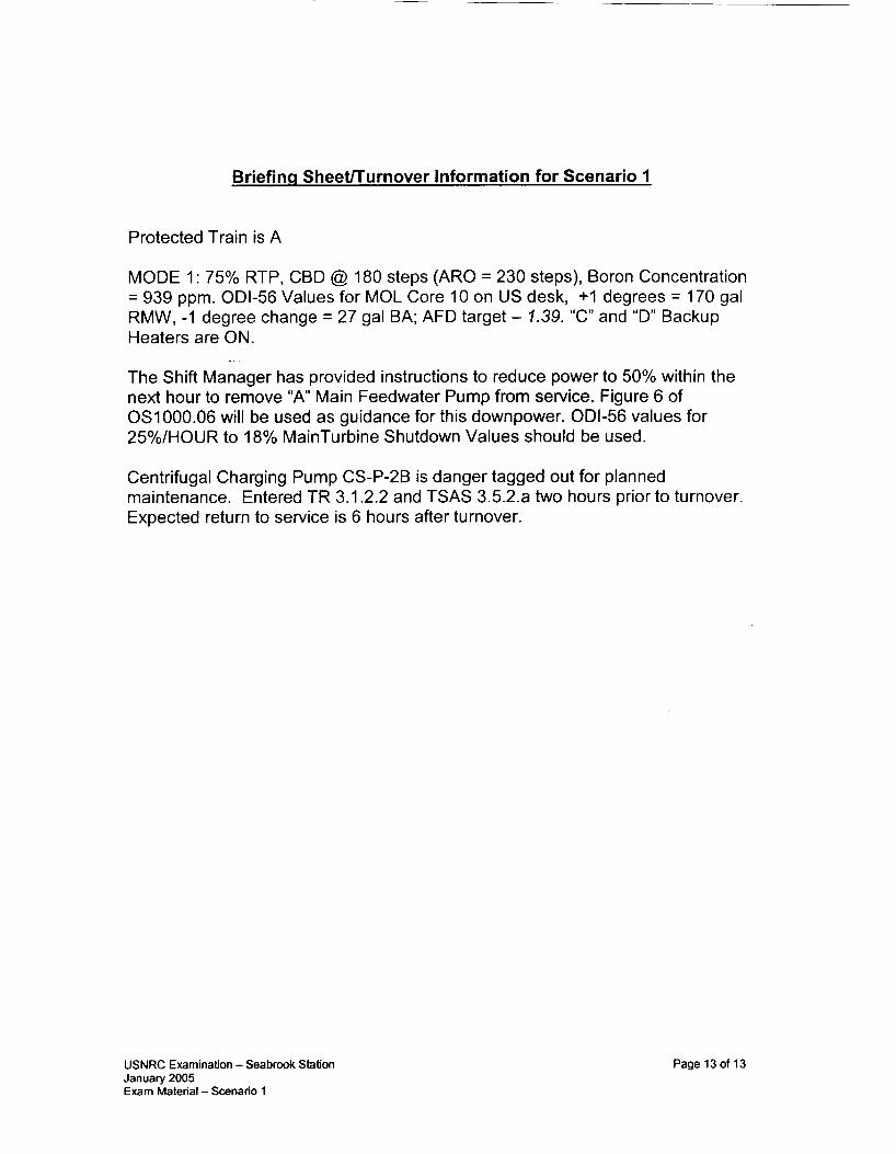
INSERT LARGE BREAK LOCA:
0
0
. SELECT: MF List SELECT: Reactor Coolant SELECT: mfRC024A SELECT: INSERT
0 0
0 A soon as SUFP trip malfunction is inserted, Insert a closure of MS-V395 which will cause P-37A (Steam Driven EFW Pump) to loss steam and secure.
SELECT: MF List SELECT: Feedwater SELECT: mfFW039 (FW-P-113 Trip - Bus 4) SELECT: INSERT
0
0
0
USNRC Examination - Seabrook Station January 2005 Exam Material -Scenario 2
SELECT: MF List SELECT: Main Steam (component) SELECT: svMSIV395 SELECT: Fails Closed SELECT: INSERT
Pageloof11

Briefing Sheetrrurnover Information for Scenario 2
Protected Train is “B”.
MODE 2: 10 -8% Power, CBD @ 90 steps (ARO = 230 steps), Boron Concentration = 947 ppm. RCS Temp is 559 F. ODI-56 Values for MOL Core 10 on US desk, + I degrees = 170 gal RMW, -1 degree change = 27 gal BA; “C” and “D” Backup Heaters are ON.
The crew assumes the watch and continues with power ascension on step 4.7 of OS1 000.07, “Approach to Criticality” then starts OS1 000.02, “Plant Startup from Hot Standby to Minimum Loading”. The power increase should not exceed 3% power.
“C” Primary Component Cooling Water Pump (P-I IC ) is danger tagged out for bearing replacement. The SUFP is supplying S/Gs via Main Feedwater Regulating Bypass Valves in AUTO. The Main Condenser is available and all MSlVs are open. A Seismic event occurred two shifts ago, Engineering Walkdowns are in progress (no other action for this is required)
USNRC Examination - Seabrook Station January 2005 Exam Material -Scenario 2
Page 11 of 11

Facility: Seabrook Scenario No.: 3 Op Test No.: 3
Examiners: Candidates:
L
Initial Conditions:
Turnover:
Mode 1. Unit is operating at 100% power. IC# 212
The ASDV for the “D” Steam Generator (MS-PV-3004) is tagged out of service due to a positioner air leak. Entered TSAS 3.3.3.5 action c, 3.6.3 action c and 3.7.1.6 action a, two hours ago. Expected outage time is 12 hours.
The Pressurizer control group heaters are tagged out of service. The control circuit for the heaters has failed to zero output. A troubleshooting plan has been developed and Electrical Maintenance is investigating the problem. The heaters have been out of service for 10 hours. Backup Heater Group “B” is ON.
1. MANUALLY trip the reactor from the control room when SSPS fails to automatically trip the reactor. [E-0]
2. MANUALLY trip the main turbine before a severe (Orange Path) challenge develops to either the Subcriticality or the Integrity CSF, or before transition to ECA-2.1, whichever happens first. [E-0]
_ _ _ Critical Tasks:
Event
1
2
3
4
5
(N
3. MANUALLY trip the “ C and “D” RCPs when subcooling is ~ 4 0 F such that an Orange path on Core Cooling does not occur when forced circulation in the I C s stops.
Malf. No.
mfHD027
N/A
ttRCTT411
mfEDOOl
mfRPSOOl
mfRPS002
mfRPS003
mfRCOl6
mfRCOl9
mfRC049D
rrnal, (R)eacti
Event Type*
C (BOP/US)
R
(ALL)
I
(ROIUS)
TS (US)
M
(ALL) C
(ROIBOP)
M
(ALL) C (ROIUS)
Event Description
“ A Heater Drain Pump Trips on overcurrent
As a result of the heater drain pump trip, a loss of feedwater preheating will result in positive reactivity and subsequent power increase. The crew will need to take positive control to restore power less than 100%.
Loop 1 Tc Instrument Fails HIGH
Loss of 13.8kV Bus 1 causes a Loss of “ A & “B” RCP’s with a failure of an automatic reactor trip (CT) and main turbine trip (CT) to occur. Note that although Safety Injection should actuate, ALL Safety Injection pumps will be prevented from manual start (malfunction numbers are not shown since no credit is taken for these failures)
Subsequent to reactor trip, the Reactor Vessel will develop a flange leak. The crew will need to trip the remaining “C” and “D” RCPs based on loss of RCS subcooling (CT). Once tripped, the RCS leak will become significantly larger to force the crew into FR-C series procedures. The “ A CCP will also trip on overcurrent.
:y, (1)nstrument. (C)omponent, (M)ajor, (TS)Technical Specification

SCENARIO 3 OVERVIEW
The crew will take the watch with reactor power at 100%. The ASDV for the “D” Steam Generator (MS- PV-3004) is tagged out of service due to a positioner air leak. TSAS 3.3.3.5 action c, 3.6.3 action c and 3.7.1.6 action a was entered two hours ago. Expected outage time is 12 hours. The Pressurizer control group heaters are tagged out of service. The control circuit for the heaters has failed to zero output. A troubleshooting plan has been developed and Electrical Maintenance is investigating the problem. The heaters have been out of service for 10 hours. Backup Heater Group “B” is ON.
After the crew assumes the watch, the “A“ Heater Drain Pump will trip on overcurrent. The crew should respond to the pump trip in accordance with OS1290.02, “Response to Condensate or Feedwater Heater System Transient”. As a result of this malfunction, the colder water being fed into the steam generators due to loss of preheating will result in a positive reactivity addition and resultant power increase greater than.rated thermal. The crew must respond by lowering turbine load.
Once power is restored below rated thermal and the crew has performed the first few steps of OS1 290.02 or at the lead examiner’s discretion, the Loop # I narrow range temperature instrument will fail HIGH. This results in Tavg for Loop # I failing high and an automatic rod insertion. The RO should take manual control of control rods and stop uncontrolled insertion. The crew will respond to the Tc instrument failure in accordance with OS1201.08, “TavglDelta T Instrument Failure”. The crew should defeat affected loop delta-T and Tavg inputs. The US should verify TS compliance.
At the discretion of the lead examiner, A Loss of 13.8kV Bus 1 will occur. The 13.8 kV Bus 1 UAT breaker trips and the associated RAT breaker fails to fast transfer. Loss of power to Bus 1 results in reactor trip demand due to loss off A & B RCPs and A & C Circulating Water pumps. The reactor fails to trip automatically and the operator is required to manually trip the reactor (CT). On the reactor trip, the automatic Turbine Trip fails. The operator is required to manually trip the main turbine (CT). The crew will enter E-0, “Reactor Trip or Safety Injection”.
Upon reactor trip, the Reactor Vessel Flange will develop a 275 gpm leak resulting in a SBLOCA. (Note to speed up the scenario and drop subcooling quicker, leak size will be increased greater than 275 gpm) This will result in Safety Injection actuation which will automatically or manually be actuated, however no SI pumps will start nor will manual starts be successful from the control room. Note that safety injection may also occur due to the cooldown associated with the Main Turbine not tripping depending on how expeditious the operators are in tripping the Main Turbine. Also note that all attempts to establish Safety Injection will NOT be successful as the intention is to force the crew into FR-C series procedure(s). The “A” CCP will trip on overcurrent following reactor trip. Because of the loss of subcooling, the crew is required by the Operator Action Summary of E-0 to trip the remaining running RCP’s (C & D) (CT). Once RCP’s are tripped the SBLOCA will become significantly larger to drive the crew into inadequate core cooling FRP’s.
Procedure progression following reactor trip is E-0 to ES-0.1, “Reactor Trip Response” and back to E-0 to E-I, “Loss of Reactor or Secondary Coolant” potentially to ECA-1 . I , “Loss of Emergency Coolant Recirculation” and then to FR-C.2, “Response to Degraded Core Cooling” (ORANGE) and/or FR-C.l (RED) when conditions are met. The scenario will end when the crew recognizes the positive displacement charging pump cannot be started because the mini-flow recirculation valve (CS-V-205) cannot be opened and/or maintenance gives the crew back one of the SI pumps or at the discretion of the lead examiner.
Simulator Operating Exam - Scenario 3
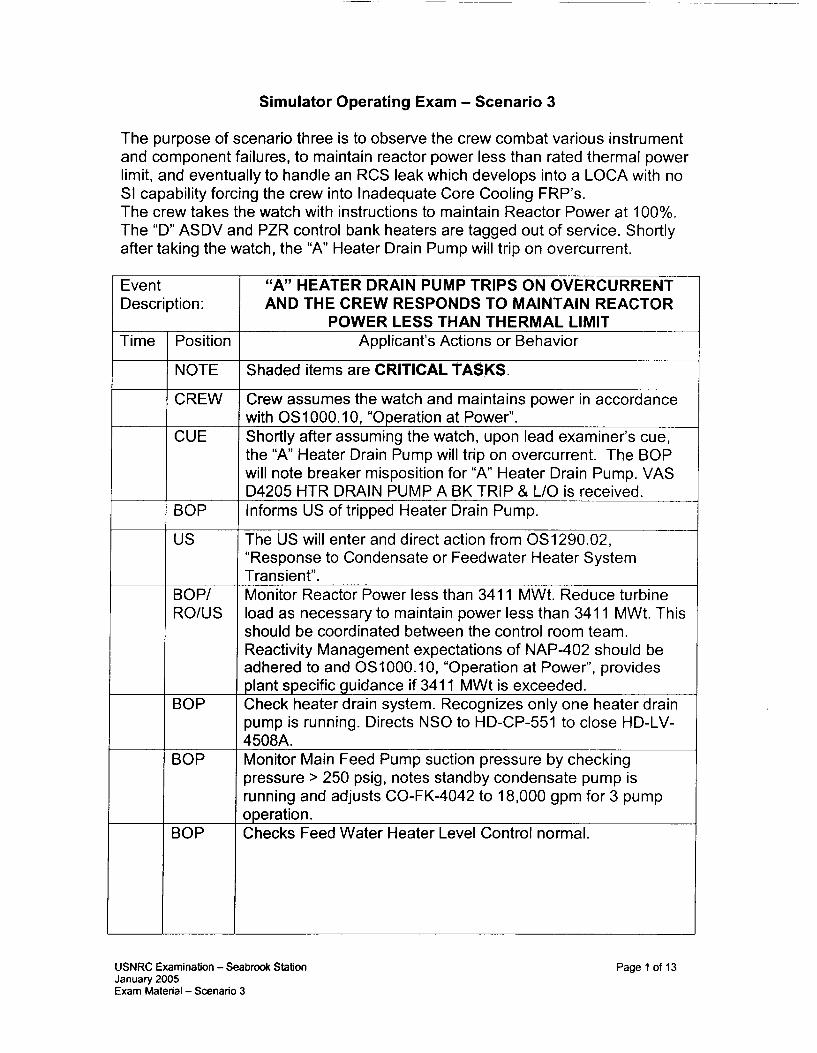
The purpose of scenario three is to observe the crew combat various instrument and component failures, to maintain reactor power less than rated thermal power limit, and eventually to handle an RCS leak which develops into a LOCA with no SI capability forcing the crew into Inadequate Core Cooling FRP’s. The crew takes the watch with instructions to maintain Reactor Power at 100%. The “D” ASDV and PZR control bank heaters are tagged out of service. Shortly after taking the watch, the “A” Heater Drain Pump will trip on overcurrent.
Event Description:
Time Position
NOTE
CREW
CUE
BOP
us
BOP/ RO/US
BOP
BOP
30P
“A” HEATER DRAIN PUMP TRIPS ON OVERCURRENT AND THE CREW RESPONDS TO MAINTAIN REACTOR
POWER LESS THAN THERMAL LIMIT Applicant’s Actions or Behavior
Shaded items are CRITICAL TASKS.
Crew assumes the watch and maintains power in accordance with OS1 000. I O , “Operation at Power”. Shortly after assuming the watch, upon lead examiner’s cue, the “A” Heater Drain Pump will trip on overcurrent. The BOP will note breaker misposition for “A” Heater Drain Pump. VAS D4205 HTR DRAIN PUMP A BK TRIP & L/O is received. Informs US of tripped Heater Drain Pump.
The US will enter and direct action from OS1290.02, “Response to Condensate or Feedwater Heater System Transient” . Monitor Reactor Power less than 341 1 MWt. Reduce turbine load as necessary to maintain power less than 341 1 MWt. This should be coordinated between the control room team. Reactivity Management expectations of NAP-402 should be adhered to and OS1000.10, “Operation at Power”, provides plant specific guidance if 341 1 MWt is exceeded. Check heater drain system. Recognizes only one heater drain pump is running. Directs NSO to HD-CP-551 to close HD-LV- 4508A. Monitor Main Feed Pump suction pressure by checking pressure > 250 psig, notes standby condensate pump is running and adjusts CO-FK-4042 to 18,000 gpm for 3 pump Dperation. Checks Feed Water Heater Level Control normal.
USNRC Examination - Seabrook Station January 2005 Exam Material - Scenario 3
Page 1 of 13

Checks Secondary Plant Stabilized. It is not the intent to process through this lengthy abnormal which checks in great detail to ensure the secondary plant has stabilized, so at the Lead Examiner discretion, the next malfunction should be implemented when sufficient reactivity manipulation has been observed. Notifies Electrical/MechanicaI Maintenance and/or Work Week Manager of heater drain pump failure and directs them to troubleshoot cause. May pass this off to the SM or WCS.
When directed by the lead examiner, a Loop 1 Tc instrument will fail HIGH resulting a HIGH Tavg for Loop 1. Auctioneered Tavg will fail high resulting in inward rod motion.
Event
I CUE
RO
RO
us
RO
RO
T
LOOP1 TC INSTRUMENT FAILS HIGH
Applicant’s Actions or Behavior
When secondary plant is stabilized from Heater Drain Pump trip and reactor power has been returned to c 341 1 MWt and upon lead examiner‘s cue, a loop 1 Tc fails high resulting in high Tavg for loop 1. The following VAS alarms will come in due to the failure: B7457 ROD MOTION DETECTED, D4422 AUCTIONEERED TAVG HIGH, and D4421 TAVG-TREF DEVIATION. The sound of rods driving inward will also cue the operators. Operators will have visual indication on loop 1 Tavg and delta-T instrumentation of which instrument has failed. RO should identify which channel is faulted by using Tavg and Delta-T instruments. Verify rod motion unnecessary and place rod control in MANUAL to stop insertion. The RO may do this very quickly prior to referencing any procedure as a skill of the operator. Enters and directs action of OS1201.08, “TAVG-Delta T I n s t ru men t Fa i I u re” Determine loop 1 TAVG channel failed HIGH.
Place rod control in MANUAL (required by procedure at this point). Depress loop 1 delta-T defeat pushbutton. Depress loop 1 Tavg defeat pushbutton. Select a non-affected channel for Delta T, Overtemperature, Overpower recorder.
JSNRC Examination - Seabrook Station January 2005 fxam Material - Scenario 3
Page 2 of 13

RO
RO
Event Description:
Time Position CUE
us
NOTE
--.
LOSS OF BUS 1 WITH FAILURE OF REACTOR/TURBINE TO TRIP, LEADING TO AN RCS LEAK AND LARGE BREAK
LOCA AND INADEQUATE CORE COOLING. Applicant’s Actions or Behavior
After the US discusses TS requirements for the failure of Tc
Restore Tavg within 1 F of Tref by manually controlling rod motion. The operators may choose to reduce turbine load instead because they are maintaining < 341 1 MWt due to the last problem -this is acceptable. Place rod control in AUTO.
Verify redundant channel bistables NOT tripped and verify technical specification compliance. TS 3.3.1 table 3.3-1 items 7 & 8. Coordinate with I&C for bypass operation or bistable tripping within 6 hours. TR-19, FW Isolation on Low RCS Tave Coincident with Reactor Trip TS Actions required: For 3.3.1 ITEMS 7 & 8: startup and/or power operation may proceed provided the inoperable channel is placed in the tripped condition within 6 hours and the minimum channels OPERABLE requirement is met. The channel may be bypassed up to 4 hours for surveillance of other channels. TR-19, FW Isolation on Low RCS Tave Coincident with Reactor Trip should be referenced.
RO/US
BOP/ us
When directed by the lead examiner, Insert a Loss of 13.8 kV Bus 1 with failure of automatic reactor & turbine trip. Subsequent to reactor trip, an RCS leak will develop requiring trip of “C” and “D” RCPs. Subsequent to RCP trip the leak develops into a large LOCA. Because all SI pumps do not start, the crew will be forced into Inadequate Core Cooling FRP’s.
required. Recognizes that a reactor trip has not occurred and is required and manually trips the reactor. (CT) Recognizes that a turbine trip has not occurred and is required and manually trips the turbine. (CT) This can be done as part
us of immediate action steps of E-0. Enters E-0, “Reactor Trip or Safety Injection”
USNRC Examination - Seabrook Station January 2005 Exam Material - Scenario 3
Page 3 of 13

RO
BOP
Note
us
RO/US.
ALL
RO/US
NOTE
ROIBOPI us
RO
30P
?O/BOP
Immediate actions: Verifies reactor trip and bypass breakers open, neutron flux decreasing, and rod bottom lights lit. Checks if SI annunciators NOT lit and verifies conditions are not met. Immediate actions: Verifies all turbine stop valves closed and generator breaker open, Verifies power to AC Emergency busses, verifies all emergency busses energized. It is possible SI may have actuated based on length of time the turbine operated post reactor trip. If SI actuated or is required, then a transition will not be made to ES-0.1 and the crew will proceed in E-0. Based on SI not required, transitions to ES-0.1, “Reactor Trip Response”. Once in ES-0.1, the developing RCS leak will cause the crew to recognize deteriorating plant conditions requires manual/or automatic actuation of SI and to return to E-0, Step 1. While in ES-0.1, the crew may perform first several steps (Monitor RCS Temperature, Check FW Status, Verfify all Control Rods Inserted, Check PZR Level and Pressure etc.) US directs transition back to E-0, Step 1 and Immediate Actions are re-performed. When RCS subcooling drops to less than 40 F, the “C” and “D” RCPs should be tripped based on Operator Action Summary for E-0. (CT) It is possible based on crew timing that the “A” CCP was not yet tripped because per the scenario, it is not tripped until subcooling decays below RCP trip criteria. Performs ESF Actuation Verification per Attachment A of E-0. 411 attempts to start any SI pumps will be unsuccessful. Informs the US the status of SI. Also notes, “A“ CCP tripped. Checks containment pressure has remained less than 18 psig by pressure recorder. This is continuous action and when sontainment pressure is > 18 psig, All Phase B status lights should be verified lit and RCPs should be stopped. derify Total EFW Flow - Greater than 500 GPM.
Monitor RCS temperature - Stable at or Trending to 557F. X S will be cooling down due to SI and EFW flow. Stop jumping steam to condenser and atmosphere. OPEN EFW nin-flow valves AND throttle total feed flow to maintain greater :han 500 gpm. When SG level is adequate based on 65% Nide range in at least two S/Gs or 5% narrow range in at least m e S/G (25% narrow range in at least one S/G if adverse), .hen throttle feed flow to restore S/G level between 25% and 50% narrow range. If cooldown continues, close MSIVs, MSlV iypasses and upstream drains.
USNRC Examination - Seabrook Station January 2005 Exam Material - Scenario 3
Page 4 of 13

RO
RO
BOP/US
RO/BOP/ us ROIBOPI us
u s RO
Note
RO/BO P/ us
BOP
NOTE
BOP/RO/ us RO
RO/US
RO
RO
Check RCS isolated. Verify letdown isolated. Verify PORVs closed. Verify normal Spray valves closed. Check if RCPs should be stopped. Should have been previously secured by OAS or if Phase “B” isolation occurred, however, if not they will be secured in this step. Check if SG Pressure Boundary is Faulted.
Check if SG U-tubes are intact.
Check if RCS is intact. Recognizes containment pressure/radiation level and containment building level are abnormal. E-I Actions Outlined Below
Directs transition to E-I , “Loss of Reactor or Secondary Coolant”. Check if RCPs should be stopped. (should already have been stopped) It is critical that RCPs are stopped. Upon first transition out of E-0, CSF Status Trees should be verified. When an orange path exists for FR-C.2 RCS Subcooling <40 F, no RCPs running, and CETs e725 F with RVLIS < 40% the crew will transition to this procedure. (FR-C.2 actions to follow) Checks if SG pressure boundary is faulted.
Check intact S/G levels. When SG level is adequate based on 65% wide range in at least two S/Gs or 5% narrow range in at least one S/G (25% narrow range in at least one S/G if adverse), then OPEN EFW min-flow valves AND throttle total feed flow to restore S/G level between 5% and 50% narrow range (25% to 50% for adverse) If S/G level is not adequate than maintain total feedwater flow >500 gpm until they are adequate. Checks secondary radiation and determines transition to E-3 is NOT necessary. Check PZR PORV and Block Valves.
Check if ECCS flow should be reduced. Based on insufficient subcooling, the US will proceed to step 7. Check if containment spray pumps should be stopped. If containment pressure has dropped below 4 psig than reset Phase B isolation and containment spray signals, stop CBS pumps and place in standby. Check if RHR pumps should be stopped. Determine RCS pressure is < 260 psig and do not stop RHR pumps. Note RHR pumps are not running.
USNRC Examination - Seabrook Station January 2005 Exam Material - Scenario 3
Page 5 of 13

I
RO/BOP
BOP
RO/US
_. .
us
RO/US
ALL
RO
RO
RO/US
us
RO
RO/US
RO
RO
Check RCS and SG Pressure. If SG pressure is NOT stable or NOT INCREASING OR RCS Pressure is NOT stable or NOT DECREASING than the crew will loop back to Step 1 of E- I until these conditions are met. If and when they are met continue with following steps. Check if EDG should be stopped. Reset SI, verify all AC busses energized by offsite power from UATs or RATS, stop and unload EDG by depressing both emergency stop pushbuttons, after EDG stopped, reset for auto start and isolate SW to EDG. Evaluate plant status by verifying cold recirculation capability. It should be recognized that cold leg recirculation capability does NOT exist without SI pumps so therefore a transition to ECA- 1 .I is warranted. Directs transition to ECA-1 . I . Continues in ECA-1 . I until FRP’s are required.
ECA-1 .I Actions Outlined Below
Check for Cold Leg Recirculation Condition (no conditions are met - go to step 8) Check Emergency Coolant Recirculation Equipment Available. Recognize power is available however RHR pumps are not operable) Should involve SM, WCS, and/or Maintenance to status repair of SI Equipment. Reset SI and automatic switchover S signal reaset for S/RWST LO-LO CBS-V8 or CBS-VI4 Auto Open. Checks RWST level > 60,000 gallons
Determines minimum containment spray requirements. Based on containment pressure, secures non-needed CBS Pumps. FR-C.2 Actions Outlined Below
When conditions are met (as described above), Directs transition to FR-C.2 Verify ECCS flow in all Trains. Checks that no CCP flow is indicated. Attempts start of PDP using Attachment A. Recognizes CS-V205, PDP mini-flow valve does not have powe; and therefore cannot be opened, therefore this is not a success path. May direct the NSO to open in the field (this will be u n su cces sfu I). Checks RCS Vent paths (PORVs, Rx Head Vents, RCS Sample Valves, Letdown and Excess Letdown Valves CLOSED) Check RCP Status - secured (go to step 7)
USNRC Examination - Seabrook Station January 2005 Exam Material - Scenario 3
Page 6 of 13

r-- RO/US
RO
BOP
BOP
Note
-_-
us
RO
RO/US
RO
RO
RO
BOP
BOP
RO
BOP
Note
NOTE
Checks core cooling which determines what path to take in this procedure. If Lead Examiner requests to restore a CCP, conditions would more than likely met to return to procedure and steD in effect. Otherwise Droceed accordinalv. Check SI Accumulator Valves Open
_ _ _ _ ~
Check intact S/G levels -narrow range > 5% (25% adverse), if not increase feedwater flow. If they are, open mini-flow valves and throttle feedwater flow. Depressurize all intact SlGs to 125 psig. Note that the “D” ASDV cannot be used for depressurization due to ASDV work. Place the simulator in freeze at Lead Examiner discretion.
FR-C.l Actions Outlined Below
When conditions are met, (CETs > I 100 F, or RCS Subcooling c 40 F with no RCPs, CETs >725 and RVLIS 40%) transition to FR-C.1 Verify ECCS flow in all Trains. Checks that no CCP flow is indicated. Attempts start of PDP using Attachment A. Recognizes CS-V205, PDP mini-flow valve does not have power and therefore cannot be opened, therefore this is not a success path. Checks RCP Support Conditions.
Check SI Accumulator Valves OPEN
Checks CETs c 1100 F
Checks Containment Hydrogen Concentration
Check intact S/G levels -narrow range > 5% (25% adverse), if not increase feedwater flow. If they are, open mini-flow valves and throttle feedwater flow. Checks RCS Vent paths (PORVs, Rx Head Vents, RCS Sample Valves, Letdown and Excess Letdown Valves CLOSED) Depressurize all intact S/Gs to 125 psig. Note that the “D” ASDV cannot be used for depressurization due to ASDV work. Place the simulator in freeze at Lead Examiner discretion.
If used for SROs in the US position, Upon completion of follow- up questioning, the SRO will perform JPM LOIT08 (Post EAL Determination and Event Classification) This will be determined by the staff based on the endpoint of the scenario.
USNRC Examination - Seabrook Station January 2005 Exam Material - Scenario 3
Page 7 of 13

Simulator Instructor Instructions for Scenario 3
Please track the following parameters in addition to the standard set (if any):
bkRHR8B RHR PUMP “B” BREAKER FAILS OPEN bkSIP6A SI PUMP “A” BREAKER FAILS OPEN bkSIP6B SI PUMP “B” BREAKER FAILS OPEN
1
2.
3.
4.
I
0
0 0 0 0
Initialize the simulator at IC #212, 100% power. (This IC is password protected for NRC security reasons. Password can be obtained from Ian Forbes or Len Hubbard ONLY)
I Protected train is ‘A’.
Ensure “B” PZR Backup Heaters are ON Place a CAUTION tag on “D” ASDV Selector Switch Place a DANGER tag on PZR Control Bank Heaters switch (ensure PTL) Ensure MS-V49 is CLOSED.
Verify the following malfunctions inserted / activated:
0 0 0 0 0 0 0 0
mfRPSOOl AUTOMATIC REACTOR TRIP FAILURE (TRAIN ‘A’) mfRPS002 AUTOMATIC REACTOR TRIP FAILURE (TRAIN ‘B’) mfRPS003 AUTOMATIC TURBINE TRIP FAILURE svMSV3004 MODULATING VALVE FAILS CLOSED bkCSl P2B 52 CC PUMP “B” BREAKER FAILS OPEN bkRHR8A RHR PUMP “A” BREAKER FAILS OPEN
Perform immediately after simulator is in RUN:
0 0 0
ENSURE simulator is stabilized and alarms are cleared. Run SIMHIST. ENSURE applicable items on Simulator Setup Checklist (NT-5701-6) are completed
USNRC Examination - Seabrook Station January 2005 Exam Material - Scenario 3
Page 8 of 13

0 0 0
0
0
USNRC Examination - Seabrook Station January 2005 Exam Material -Scenario 3
0s1000.10 OS1290.02 OS1201.08 E-0, ES-0.1 E-I, ECA-1 .I , FR-C.2, FR-C.l
Page 9 of 13

Shortly after the crew assumes the watch and only after lead examiner’s cue:
“A” Heater Drain Pump Trips.
0 0 0 0 0
0 0 0 0
SELECT: MF List SELECT: Reactor Coolant (component) SELECT: ttRCTT411 SELECT: Fail HIGH SELECT: INSERT
SELECT: MF List SELECT: Heater Drains SELECT: mfHD027 SELECT: INSERT
When directed by the operating crew, throttle HD-LV-4503A as follows:
0 0 0 0 0
SELECT: LOCAL PANELS SELECT: Feedwater/MVD SELECT: Fischer Porter Heater Drains CLICK on 1-HD-LY-4508-A right arrow & INPUT 0 for value SELECT: INSERT
When directed by lead examiner:
The crew will contact I&C to respond to TT-411. Simulator operator will play role of I&C. When directed by crew, bypass PT-411. If the crew does not make a decision on bypass/trip status, call in as SM and direct BYPASS of PT-41 I.
To select operator bypass for TT-411:
0 0 0 0 0 0 0
SELECT: Panel Overview SELECT: BTI CP1 SELECT: CP1 Door Open SELECT: The NORM/ENABLE switch to ENABLE TOGGLE: TB411G OP-Delta T to bypass TOGGLE: TB411 C OT-Delta T to bypass TOGGLE: TB412G Low Tavg for Feedwater to bypass
USNRC Examination - Seabrook Station January 2005 Exam Material - Scenario 3
Page 10 of 13

0 I TOGGLE: TB412D Low Low Tavg for P-12 to bypass When directed by lead examiner:
0
0
INSERT LOSS OF BUS 1:
SELECT: MF List SELECT: Electrical Distribution SELECT: mfEDOOl SELECT: FAILS OPEN SELECT: INSERT
0 0 0
0
SELECT: MF List SELECT: Reactor Coolant SELECT: mfRCO19 ENTER: Final Value of 275 gpm SELECT: INSERT
As required to drop RCS subcooling, (THIS MUST OCCUR IF SI HAS ALREADY ACTUATED OR WHEN IT IS ACTUATED), increase RCS leak:
0 0 0
0 0
SELECT: MF List SELECT: Reactor Coolant System SELECT: mfRC049D INSERT: Value of 1500 gpm INSERT: Ramp time of 60 seconds SELECT: INSERT
USNRC Examination - Seabrook Station January 2005 Exam Material - Scenario 3
Page 11 of 13

AFTER RCPs HAVE BEEN TRIPPED due to Loss of RCS Subcooling, increase RCS leak substantially to deplete core inventory and force the crew into FR-C series. (May need to increase the rate when SI accumulators dump to speed up time required to heat up core and to enter FRP’s -- ie: change to 150,000 over 600 seconds or insert mfRCO24D-Double ended Hot Leg Break) (Note that Step 7 of FR-C.2 is a transition back to E-1 if the orange path has cleared. Increasing the break size will prevent this transition by depleting core inventory quicker and force the crew into FR-C.l)
0 0 0 0 0 0
SELECT: MF List SELECT: Reactor Coolant System SELECT: mfRC049D INSERT: Value of I00000 gpm INSERT: Ramp time of 600 seconds SELECT: MODIFY
AFTER INCREASING RCS LEAK SIZE, trip the “A” CCP:
0
0
SELECT: MF List SELECT: Chemical and Volume Control SELECT: mfCSO16 SELECT: INSERT
If called to open CSV205, report after a short while that CS-V205 could not be locally opened and that maintenance has been informed.
USNRC Examination - Seabrook Station January 2005 Exam Material - Scenario 3
Page 12 of 13

Briefing Sheernurnover Information for Scenario 3
Protected Train is A
MODE 1: 100% Power, CBD @ 230 steps (ARO = 230 steps), Boron Concentration = 899 ODI-56 Values for MOL Core 10 on US desk, +I degrees = 170 gal RMW, -1 degree change = 27 gal BA; AFD target - 7.92%, Current AFD
-__
- 7.92%.
The crew assumes the watch and continues to maintain Reactor Power at 100% in accordance with OS1 000.1 0, “Operations at Power”.
The Pressurizer Control Group heaters are tagged out of service. The control circuit for the heaters was failed to zero output. A troubleshooting plan has been developed and Electrical Maintenance is investigating the problem. The heaters have been out of service for 10 hours. Backup Heater Group “B” is ON.
“D” ASDV (MS-PV-3004) is out of service due to a positioner air leak. The upstream isolation (MS-V49) is DANGER tagged. TSAS 3.3.3.5 action c, 3.6.3 action c and 3.7.1.6 action a were entered two hours ago. Expected outage time is 12 hours. The selector switches on the MCB and RSS have been CAUTIONED tagged to allow I&C to operate the ASDV. The work package includes instruction to contact the Control Room prior to causing valve to open.
USNRC Examination - Seabrook Station January 2005 Exam Material - Scenario 3
Page 13 of 13

Facility: Sea broo k Scenario No.: 4 Op Test No.: Spare if needed
Examiners: Candidates:
N/A
mfCSOl6
mfAR005A
mfED038
cSWVl6
mfED033
mfSG002A
Initial Conditions: Mode 3. Reactor Startup in progress. Shutdown Banks have been withdrawn. IC# 213
~ ~~
R (ALL)
N (ALL)
TS (US)
C (RO/US)
TS (US)
C
(BOP/US)
M
(ALL) C
(BOP/U S )
M (ALL)
Turnover: The crew will take the shift and continue with reactor startup at step 4.4 of OS1000.07. PZR Sprays are being forced using two banks of backup heaters. Startup Feedwater Pump is running powered from Bus 4 supplying S/G’s via Main Feedwater Regulating Bypass Valves. All MSIV’s are open and condenser vacuum has been established. Steam Dump control is in the Steam Pressure Mode.
TS Surveillance 4.1.1.4 (monitoring RCS temperature) has been entered and being monitored every 15 minutes.
NO equipment is out of service and Mode 2 checklist and TS logs have been completed.
Severe Weather (high winds) is anticipated sometime during your shift.
1. MANUALLY actuate at least one train of SI actuated safeguards before transition to any E-I, E-2, E-3 or FRP. [E-0]
2. ISOLATE feedwater flow into and steam flow from the ruptured SIG before a
Critical Tasks:
mfMS049A
mfRPS007
mfRPS008
Event No.
1
M (ALL)
I
(ROWS)
2
3
4
5
transition to E Malf. No. Event
:A-3.1 is required. [E-31
Event Description
Withdraw control bank rods during reactor startup.
Trip of Centrifugal Charging Pump CS-P2A
Trip of “ A Mechanical Vacuum Pump
Offsite power is lost resulting in a reactor trip. The “ A EDG will start and load onto Emergency Bus 5, however, its associated SW cooling valve (SW-Vl6) will not automatically open and must be manually opened. The “B” EDG will fail to start. Upon reactor trip, a large Steam Generator Tube Rupture in the “ A S/G at 500 gpm will occur.
RCS pressure will continue to drop post trip due to SGTR and the crew must manually actuate Safety Injection (CT) due to failure of automatic SI. After SI actuation, the “ A SIG will fault inside containment. Procedure progression will be E-0 to E-2 to E-3 to ECA-3.1. FR-2.1 may also be entered.
I

SCENARIO 4 OVERVIEW
Note that this is a backup scenario or can be used in lieu of any of the other scenarios at Lead Examiners discretion.
The crew will take the shift with a reactor startup in progress currently at step 4.4 of OS1000.07. All shutdown banks of control rods have been withdrawn.
After the crew assumes the watch, they will continue the reactor startup be withdrawing control banks and plotting 1/M data in accordance with OS1000.07, “Approach to Criticality”. Once the lead examiner is satisfied with the reactivity addition and TS compliance with the reactor startup, the “A” CCP will trip on overcurrent. The crew should respond to the failure in accordance with OS1 202.02, “Charging System Failure”. The crew should also establish priorities regarding reactor startup and recognize that a mode change is not allowed. Letdown will be isolated by closing CS-V-145 and the “B” CCP will be started. The US will verify TS compliance at the discretion of the lead examiner during or following the scenario.
Once letdown is restored or at the discretion of the lead examiner, the running vacuum priming pump (P-50A) will trip. The should reference the VAS alarm procedure (F5117) and start a standby pump. The crew may also respond in accordance with ON1 233.01, “Loss of Condenser Vacuum”. This procedure has the crew manually start the standby mechanical vacuum pumps, and provides criteria to trip the plant which should not be necessary as starting the standby pump will restore vacuum. Note condenser vacuum is not adversely affected at this power level by a loss of one vacuum priming pump.
At the lead examiners discretion, a Loss of Off-Site Power will occur. A subsequent reactor trip will automatically occur. The “A” EDG will automatically start and load onto Bus 5, however it’s associated SW cooling valve (SW-V16) will not automatically open. The crew must recognize that this valve is closed and open it to prevent overheating the only running EDG. The “B” EDG will not automatically or manually start, resulting in a loss of power to Bus 6. A loss of charging and subsequent letdown (note letdown may still be isolated based on examiner discretion) will occur due to previous failure of the “A” CCP.
Upon reactor trip, a Steam Generator Tube Rupture will occur at 500 gpm. The crew must manually actuate Safety Injection (CT), because automatic SI has failed. Upon SI actuation, a fault in the “A” Steam Generator will occur inside containment
Procedure progression following reactor trip is E-0, “Reactor Trip or Safety Injection” to E-2, “Faulted Steam Generator Isolation” to E-3, “Steam Generator Tube Rupture” to ECA-3.1, “SGTR with Loss of Reactor Coolant - Subcooled Recovery Desired”. (May transition to ES-0.1, “Reactor Trip Response” for a short time until SGTL progresses and SI criteria are met) Steam flow must be secured to the steam driven feedwater pump from the ruptured Steam Generator (A) and feedwater flow must also be secured (CT) prior to transition to ECA-3.1. Note that FR-Z.l may also be entered based on high containment pressure (time dependant).

Simulator Operating Exam - Scenario 4
Event Description:
Time Position
NOTE
The purpose of scenario four is to observe the crew perform a portion of a reactor startup while prioritizing and maintaining control of reactivity management during various component failures. Eventually a loss of off-site power occurs resulting in an automatic reactor trip. Subsequent to reactor trip, the crew is challenged with only one train of safeguards during a ruptured and faulted S/G event. The crew takes the watch with instructions to continue reactor startup from the point of shutdown bank rods fully withdrawn. No equipment is out of service. Shortly after taking the watch, the crew will continue with reactor startup. When the Lead Examiner is satisfied with rod withdrawal and 1/M plotting, and upon his cue, the “A” C.entrifugal Charging Pump will trip on overcurrent.
WHILE PERFORMING REACTOR STARTUP, THE “A” CENTRIFUGAL CHARGING PUMP TRIPS ON
OVERCURRENT Applicant’s Actions or Behavior
Shaded items are CRITICAL TASKS. I I
Reactivity Manipulation
CREW
us us
US/RO
RO
1 Surrogate ’
JRO
Crew assumes the watch and continues reactor startup in accordance with OS? 000.07, “Approach to Criticality”, step 4.4. Directs reactivity manipulations and supervises reactor startup.
Verifies predicted critical conditions within 4 hours of criticality, (RCS Cb within 15 ppm of critical Cb, Net poison worth within 150 pcm of ECP value, Critical rod height above RIL) Verifies all S/D banks withdrawn within 15 minutes of control bank withdrawal, logs lowest operating Tavg > 551 F every 15 minutes until critical. Announce reactor startup has begun. Withdraws control rods using guidance of OS1 007.01, “Automatic and Manual Rod Control”. During rod withdrawal stops when count rate doubles or approximately every 50 steps which ever occurs first. After each pull after Count Rate has stabilized & 1/M plotted by surrogate, continues with next rod
Peer checks reactivity manipulations (can also be performed by US with a three man crew) Plots 1/M data after each rod pull. (Normally performed by Reactor Engineering) Monitors nuclear instrumentation. Do NOT exceed 1 dpm.
pull.
JSNRC Examination - Seabrook Station January 2005 Exam Material - Scenario 4
Page 1 of 11

CUE
RO
us
RO
RO --_
RO
RO
RO
RO
RO/US
RO
RO
us
NOTE
Centrifugal Charging Pump Trips
After the Lead Examiner is satisfied with reactor startup, and upon lead examiner‘s cue, the “A” Centrifugal Charging Pump will trip on overcurrent. The RO should note breaker misposition for “A” Centrifugal Charging Pump. The trip also results in VAS alarm 04652 CTRFGL CHG PUMP BKR TRIP & L/O and the RCP SEAL INJECTION FLOW LO annunciator. Verifies pump trip and informs US.
Enters and directs actions of OS1 202.02 , “Charging System Failure” or OS1 202.02. “Loss of Letdown” Isolates letdown due to rapidly rising temperatures and flashing in the regenerative HX. CLOSE CS-V145. Place CS-FK-121 in manual and minimum output.
Start CS-P-2B.
Slowly increase output on CS-FK-121 to establish charging flow. Adjust CS-HCV-182 as necessary to restore RCP seal flow.
Checks seal injection flow status. Checks seal injection filter DP 19 PSID, seal injection flow > 6 gpm to each RCP. Checks charging system intact. Checks PAB rad levels, sump levels and directs PAB walkdown Establish normal letdown: Verifies CC-V341 OPEN, place CS- TK-130 in AUTO, CLOSE CS-HCV-189, CLOSE CS-HCV-190,
establish letdown flow using letdown flow control valves. Flow is restored by slowly opening CS-PK-131, CS-HCV-189 or CS-
OPEN RC-LCV-459, OPEN RC-LCV-460, OPEN CS-V145,
HCV-190. Restore normal PZR level control. Re-establish PZR level within band. Ensure RCP seal injection between 8 and 13 gpm. Verify TS Compliance. TS 3.5.2 ECCS Subsystems - Tavg Greater than 350F. TS 3.0.4, precludes a mode change. TR-29; Boration Systems. TS 3.5.2 with one ECCS subsystem inoperable, restore the inoperable subsystem to operable status within 7 days. TS 3.0.4, recognizes cannot continue to enter Mode 2 and secures reactor startup.
USNRC Examination - Seabrook Station January 2005 Exam Material - Scenario 4
Page 2 of 11

When directed by the lead examiner, the only running Mechanical Vacuum Pump (“A’), will trip resulting in a minor loss of condenser vacuum.
Event
us
BOP
US/RO BOP
t I us I
I I
“A” MECHANICAL VACUUM PUMP TRIPS
Applicant’s Actions or Behavior
When the lead examiner is satisfied with US TS review for “A” CCP and upon lead examiner’s cue, the “A” Mechanical Vacuum Pump will trip. VAS alarm F5117 will be received and the amber light indicating breaker misposition above the “A” Mechanical Vacuum PumD will be lit. Verifies pump trip and informs US.
~~~ ~~
Enters and directs actions for VAS Response for F5117 and/or ON1233.01 , “Loss of Condenser Vacuum”. Manually starts a standby Mechanical Vacuum Pump (“B” or
Monitors condenser vacuum to ensure it recovers. If Loss of Condenser Vacuum is entered, it provides guidance to trip the reactor if vacuum is < 25 inches HG. It is highly unlikely that this would be the case. Directs WCS, SM or Maintenance to provide a status of the Mechanical Vacuum pump. The US should recognize there is no TS imdication bv this failure.
“C’,).
When directed by the lead examiner, Insert Loss of Offsite Power. Immediately upon reactor trip, a SGTR in the “A” S/G will be inserted at a rate of 500 gpm which is beyond the capacity of CCP(s). This will require manual SI actuation since the automatic actuation has failed (CT)
Event Description:
LOSS OF OFFSITE POWER RESULTING IN AUTO REACTOR TRIP AND FAILURE OF “B” EDG TO START AND LOSS OF COOLING WATER TO “A” EDG. ALSO
UPON REACTOR TRIP, A 500 GPM SGTR DEVELOPS IN THE “A” S/G REQUIRING MANUAL SI. FOLLOWING SI,
THE RUPTURED S/G ALSO BECOMES FAULTED. Applicant’s Actions or Behavior
After the crew recovers from the loss of mechanical vacuum pump trip and at the discretion of the lead examiner, a Loss of Offsite Power will be inserted. Numerous control room alarms will actuate. A plant trip will occur and only the “A’ EDG will recover Bus 5 restoring only partial control room lighting and one train of safeauards.
USNRC Examination - Seabrook Station January 2005 Exam Material - Scenario 4
Page 3 of 11

us RO
NOTE
BOP
-..
RO/US
RO/BOP/ us
RO
BOP
ROlBOP
RO
RO
Directs entry into E-0, “Reactor Trip or Safety Injection”
Immediate actions: Verifies reactor trip and bypass breakers open, neutron flux decreasing, and rod bottom lights lit. Checks if SI annunciators NOT lit and verifies conditions are not met. Should note degrading RCS conditions (RCS pressure dropping, PZR level dropping and RCS subcooling dropping) and actuate SI. Auto SI has failed, so it is critical to actuate SI. The crew may transition to ES-0.1 in which case degrading plant conditions will require SI and transition back to E-0. Immediate actions: Verifies all turbine stop valves closed and generator breaker open, Verifies power to AC Emergency busses, verifies only Bus 5 emergency bus is energized. May attempt one emergency start of “B” EDG which will be unsuccessful. Mahually actuates at least one train of Safeguards before transition to any E-I, E-2, E-3, or CSF Procedure. (other than
Performs ESF Actuation Verification per Attachment A of E-0. Notes that the “A EDG SW cooling valve (SW-V16) has not automatically opened and manually opens this valve. Note that all Train “B” components do NOT have power and therefore will be unable to be started. This status should be reported to the us. Checks containment pressure has remained less than 18 psig by pressure recorder. Verify Total EFW Flow - Greater than 500 GPM.
ES-0. I) (CT)
~~ ~
Monitor RCS temperature - Stable at or Trending to 557F. RCS will be cooling down due to SI and EFW flow. Stop dumping steam to condenser and atmosphere. OPEN EFW min-flow valves (only FW-V-346 has power and can be opened from the MCB) AND throttle total feed flow to maintain greater than 500 gpm. When SG level is adequate based on 65% wide range in at least two S/Gs or 5% narrow range in at least one S/G (25% narrow range in at least one SIG if adverse), then throttle feed flow to restore S/G level between 25% and 50% narrow range. If cooldown continues, close MSIVs, MSlV bypasses and upstream drains. Check RCS isolated. Verify letdown isolated. Verify PORVs closed. Verify normal Spray valves closed. Check if RCPs should be stopped. If subcooling drops to <40F with SI pumps running than RCPs will be secured. This is also a continuous action on the OAS page.
USNRC Examination - Seabrook Station January 2005 Exam Material - Scenario 4
Page 4 of 11

FR-2.1 Actions Outlined Below
BOP/US
I I
Check if SG Pressure Boundary is Faulted. Should recognize the “A” S/G pressure is decreasing in an uncontrolled manner
RO/US t-r-
Note
L
and transition to E-2, “Faulted Steam Generator Isolation”. Upon first transition out of E-0, CSF Status Trees should be
Upon first transition out of E-0, Critical Safety Function monitoring should begin. This procedure may or may not be entered based on current plant conditions and crew timing. If an orange or red path exists for FR-2.1 due to high containment pressure and/or Bus 6 de-energization causes boundary valves not to close, the crew will transition to this procedure and carry out actions as outlined below. Verify Containment Isolation Phase A. Determines Phase A Isolation has not occurred on Bus 6. Direct alignment of valves
BOPIUS
ALL
BOP
ALL
which have not aligned and do not have power. Check if containment spray is required. Checks all Phase B
Identifies “A” SIG as the faulted S/G.
Checks “A” S/G feed and steam lines isolated. (CT) Checks Main feedline isolated, EFW flow isolated, MS-V393 MUST be closed, SIG ASDV Closed, Main Steam drains MSD-V44 closed, S/G Blowdown SB-V9 closed. Check CST level greater than 250,000 gallons.
Checks secondary radiation and determines transition to E-3, “Steam Generator Tu be Rupture”, is necessary.
status lights lit. If greater than 18-psig, determines “A’ Spray
us RO
pump is running. “B” pump has no power. Verify at least one containment enclosure cooling fan is runnina.
Directs transition to E-3, “Steam Generator Tube Rupture”.
Check if RCPs should be stopped. (Note RCPs are tripped due to Loss of Off-Site Power)
Verify MSIVs, bypasses and upstream drains isolated.
Check if feed flow should be isolated to any SG. Isolation of feedwater/ENV to “A” S/G could occur in this step (CT) Check hydrogen concentration and exit this procedure to return to procedure and step in effect.
E-2 Action Outlined Below
I verified. BOP I Check MSlVs and bypasses for all S/Gs closed
I
BOP 1 Check if S/G pressure in any S/G is stable or increasing.

ALL
BOP
BOP/US
RO
BOPlUS
RO -
RO
Note
Identifies that the “A” S/G is ruptured.
Isolates flow from ruptured S/G. Adjusts “A” S/G ASDV controller setpoint to 1125 psig and checks this valve closed, reverifies MS-393, SB-V9, MSD-V44, and MSIV/bypass valves are closed (previously should have been closed in E-2) Checks “A S/G level. Regardless of level the caution applies and feed flow should NO? be reinitiated to this S/G. Checks ruptured S/G isolated from intact S/G’s. “A” MSlV and associated bvDass closed. Check “A” S/G pressure > 350 psig. Since it is not, the US should direct transition to ECA-3.1, “SGTR with Loss of Reactor Coolant-Subcooled Recovery Desired”. Resets SI.
~~
Resets Containment Isolation Phase A and Phase 6.
Place the simulator in freeze at Lead Examiner discretion.
USNRC Examination - Seabrook Station January 2005 Exam Material - Scenario 4
Page 6 of 11

Simulator Instructor Instructions for Scenario 4
1.
Please track the following parameters in addition to the standard set (if any):
Initialize the simulator at IC #213, Reactor Startup with shutdown banks withdrawn. (This IC is password protected for NRC security reasons. Password can be obtained from Ian Forbes or Len Hubbard ONLY)
0 0 0 0
0
2. 0 I Protected train is ‘A’. 1
- ~
mfED033 DG-1B AUTO START FAILURE mfRPS007 SI FAILS TO AUTO ACTUATE (TRAIN “ A ) mfRPS008 SI FAILS TO AUTO ACTUATE (TRAIN “B”) IOOZMDIDGS595221 DIESEL GENERATOR B EMERGENCY STOP PB to STOP IOOZMDIDGS595222 DIESEL GENERATOR B EMERGENCY STOP PB to STOP
3. 0 Ensure “C” & “D” PZR Backup Heaters are ON
0 Ensure completed ECP and Blank 1/M sheets are available.
4. Verify the following malfunctionskomponent malfunctions & 110 overrides inserted / activated:
USNRC Examination - Seabrook Station January 2005 Exam Material - Scenario 4
Page 7 of 11

~~
Perform immediately after simulator is in RUN:
0
0 0 0
0 0
0 0
OS1000.07 signed off to applicable step per turnover, OS1007.01 os1202.02 ON1233.01 E-0, ES-0.1
ECA-3.1 E-2, E-3
ENSURE simulator is stabilized and alarms are cleared. Run SlMHlST ENSURE applicable items on Simulator Setup Checklist (NT-5701-6) are completed SELECT: EVENT TRIGGERS SELECT: LENS SW SELECT: ACTIVATE (removes override from SW-V-16 when operator opens the valve from MCB)
Ensure the following Procedures are Available:
USNRC Examination - Seabrook Station January 2005 Exam Material - Scenario 4
Page8of 11

Shortly after the crew assumes the watch, performs reactivity manipuation and only after lead examiner‘s cue:
0 0 0
“A” Centrifugal Charging Pump Trips.
SELECT: MF List SELECT: Condenser Air Evacuation SELECT: mfAR005A SELECT: INSERT
0 I SELECT: MF List
0 0 0 0
0 I SELECT: Chemical and Volume Control
SELECT: MF List SELECT: Electrical Distribution SELECT: mfED038 SELECT: INSERT
0 0
SELECT: mfCSO16 SELECT: INSERT
When directed by lead examiner: -. ~
Trip of “A” Mechanical Vacuum Pump (P-50A).
When directed by lead examiner:
INSERT LOSS OF OFFSITE POWER:
AS SOON AS CREW HAS ENTERED E-0, “Reactor Trip or Safety Injection”, INSERT a SGTR into the “A” SIG at 500 gpm requiring SI which must be manually actuated.
0 0 0 0 0 0
SELECT: MF List SELECT: Steam Generator SELECT: mfSG002A INSERT: Ramp Time of 100 seconds INSERT: Final Value of 500 gpm SELECT: INSERT
USNRC Examination - Seabrook Station January 2005 Exam Material - Scenario 4
Page9of 11

AFTER THE CREW MANUALLY ACTUATES SI insert a fault on the same SIG:
0 0 0 0 0 0
SELECTI-MF List SELECT: Main Steam SELECT: mfMS049A INSERT: Ramp Time of 3000 INSERT: Final Value of 1 SELECT: INSERT
USNRC Examination - Seabrodc Station January 2005 Exam Material - Scenario 4
Page 10 of 11

Briefing Sheetrrurnover Information for Scenario 4
Protected Train is A
MODE 3: Reactor Startup in progress. Shutdown Banks have been withdrawn. Boron Concentration = 595 ppm, Tavg is 558 F, ECP has been calculated and is provided for review.
The crew will take the shift and continue with reactor startup at step 4.4 of OS1000.07.-PZR Sprays are being forced using “C” & “D” banks of backup heaters. Startup Feedwater Pump is running powered from Bus 4 supplying S/G’s via Main Feedwater Regulating Bypass Valves. All MSIV’s are open and condenser vacuum has been established. Steam Dump control is in the Steam Pressure Mode.
TS Surveillance 4.1 .I .4 (monitoring RCS temperature) has been entered and being monitored every 15 minutes.
No equipment is out of service and Mode 2 checklist and TS logs have been completed.
Severe Weather (high winds) is anticipated sometime during your shift.
USNRC Examination - Seabrook Station January 2005 Exam Material - Scenario 4
Page 11 of 11