D-5 OUTLINE SPECIFICATION FOR ENERGY MANAGEMENT … · OUTLINE SPECIFICATION FOR ENERGY MANAGEMENT...
57
CC EDITION 10/04 OUTLINE SPECIFICATION FOR ENERGY MANAGEMENT CONTROL SYSTEM D-5.1 D-5 OUTLINE SPECIFICATION FOR ENERGY MANAGEMENT CONTROL SYSTEM HVAC INSTRUMENTATION AND CONTROLS PART I GENERAL: This document provides performance requirements and guideline information for the HVAC instrumentation and controls for Colorado College only, and is not intended for use, in whole or in part, as a specification. The purpose of providing this information is to communicate overall site-specific information and technical requirements for the Consultants review prior to the design phase of any project. The Owner believes this information will enhance the overall design of any mechanical project for Colorado College by keeping design solutions both simple and effective for the operations of the campus. Do not copy this information verbatim in specifications or in notes on drawings. Refer questions and comments regarding the content and use of the document to the Colorado College Facilities Services. 1.1 RELATED DOCUMENTS A. Drawings and general provisions of the Contract, including General and Supplementary Conditions and Division 1 Specification Sections, apply to this Section. 1.2 SUMMARY A. This Section includes the Facility Management System (FMS) control equipment for HVAC systems and components, including open protocol control components for terminal heating and cooling units. B. All labor, material, equipment and software not specifically referred to herein or on the plans, that are required to meet the functional intent of this specification, shall be provided without additional cost to the Owner.
Transcript of D-5 OUTLINE SPECIFICATION FOR ENERGY MANAGEMENT … · OUTLINE SPECIFICATION FOR ENERGY MANAGEMENT...

CC EDITION 10/04 OUTLINE SPECIFICATION FOR ENERGY MANAGEMENT CONTROL SYSTEM D-5.1
D-5 OUTLINE SPECIFICATION FOR ENERGY MANAGEMENT CONTROL SYSTEM HVAC INSTRUMENTATION AND CONTROLS PART I
GENERAL: This document provides performance requirements and guideline information for the HVAC instrumentation and controls for Colorado College only, and is not intended for use, in whole or in part, as a specification. The purpose of providing this information is to communicate overall site-specific information and technical requirements for the Consultants review prior to the design phase of any project. The Owner believes this information will enhance the overall design of any mechanical project for Colorado College by keeping design solutions both simple and effective for the operations of the campus. Do not copy this information verbatim in specifications or in notes on drawings. Refer questions and comments regarding the content and use of the document to the Colorado College Facilities Services.
1.1 RELATED DOCUMENTS
A. Drawings and general provisions of the Contract, including General and Supplementary Conditions and Division 1 Specification Sections, apply to this Section.
1.2 SUMMARY
A. This Section includes the Facility Management System (FMS) control equipment for HVAC systems and components, including open protocol control components for terminal heating and cooling units.
B. All labor, material, equipment and software not specifically referred to herein or on the plans, that are required to meet the functional intent of this specification, shall be provided without additional cost to the Owner.

CC EDITION 10/04 OUTLINE SPECIFICATION FOR ENERGY MANAGEMENT CONTROL SYSTEM D-5.2
C. Related Sections include the following: 1. Section 13850 – Fire Alarm Systems. 2. Section 15010 – Commissioning. 3. Section 15050 – Basic Mechanical Requirements. 4. Section 15650 – Refrigeration Equipment. 5. Section 15763 – Air Handling Equipment. 6. Section 15980 – Test and Balance. 7. Section 16050 – Basic Electrical Requirements. 8. Section 16127 – Cables, Low Voltage (600 Volts and below. 9. Section 16140 – Wiring Devices 10. Section 16480 – Motor Control Centers. 11. Section 16xxx – Basic Electrical Materials. 12. Section 16xxx – Uninterruptible Power Supply. 13. Section 16xxx – Emergency Systems.
1.3 DEFINITIONS
A. ARP: Address Resolution Protocol
B. ASC: Application Specific Controller.
C. FMS: Building Management System
D. CAC: Custom Application Controller.
E. CSMA/CD: Carrier Sense Multiple Access/Collision Detect
F. DDC: Direct Digital Control
G. DDE: Dynamic Data Exchange
H. FTT: Free Topology Transceivers
I. GUI: Graphical User Interface
J. HVAC: Heating, Ventilation, and Air Conditioning
K. LAN: Local Area Network
L. LSC: Interoperable Legacy System Controller
M. MER: Mechanical Equipment Room
N. ODBC: Open DataBase Connectivity
O. PID: Proportional, Integral, Derivative
P. PES: Portable Engineering Station

CC EDITION 10/04 OUTLINE SPECIFICATION FOR ENERGY MANAGEMENT CONTROL SYSTEM D-5.3
D. The Enterprise Ethernet (IEEE 802.3) LAN shall utilize Carrier Sense Multiple/Access/Collision Detect (CSMA/CD), Address Resolution Protocol (ARP) and User Datagram Protocol (UDP) operating at 100 Mbps.
Q. POT: Portable Operator’s Terminal
R. SNVT: Standard Network Variables Types
S. SQL: Structured Query Language
T. UDP: User Datagram Protocol
U. UNC: Universal Network Controller
V. VAV: Variable Air Volume Box
1.4 SYSTEM DESCRIPTION Ethernet (IEEE 802.3), peer-to-peer CSMA/CD
A. Furnish all labor, materials, equipment, and services necessary for a complete and operating temperature control system, utilizing a high speed peer to peer network of interoperable Direct Digital Controls (DDC), Graphical User Interface (GUI) with color graphic displays available on at least 64 client computers, and pneumatic/electronic interfaces and actuation devices, as shown on the drawings and as described herein.
B. The Facility Management System (FMS) shall be comprised of an Universal Network Controller or Controllers (UNC) within each building. The UNC shall connect to the Colorado College local area network. Access to the system, either locally in each building, or remotely from the existing central facilities maintenance computer located in the Central Heating Plant shall be accomplished through standard Web browsers, via the Internet and/or local area network. Each UNC shall communicate to LonMark/LonTalk (IDC), Legacy System (LSC) controllers and/or BACnet (IBC) controllers.
C. The Local Area Network (LAN) shall be 100 Mpbs Ethernet network supporting BACnet, Java, XML, HTTP, and CORBA IIOP for maximum flexibility for integration of building data with enterprise information systems and providing support for multiple Universal Network Controllers (UNCs), user workstations and a local host computer system.
E. The system will consist of an open architecture that utilizes EIA standard 709.1, the LonTalk™ protocol, as the common communication protocol between all controllers and integral ANSI / ASHRAE™ Standard 135-1995, BACnet functionality to assure interoperability between all system components. Both the LonTalk™ protocol and the ANSI / ASHRAE™ Standard 135-1995, BACnet protocol are required to assure that the project is fully supported by the two leading HVAC open protocols to reduce future building maintenance, upgrade, and expansion costs.

CC EDITION 10/04 OUTLINE SPECIFICATION FOR ENERGY MANAGEMENT CONTROL SYSTEM D-5.4
F. Where necessary or desired, LonTalk™ packets may be encapsulated into TCP/IP messages to take advantage of existing infrastructure or to increase network bandwidth.
1. Any such encapsulation of the LonTalk™ protocol into IP datagrams shall
conform to existing LonMark™ guide functionality lines for such encapsulation and shall be based on industry standard protocols.
2. The products used in constructing the FMS shall be LonMark™ compliant.
3. In those instances in which Lon-Mark™ devices are not available, the FMS contractor shall provide LonWorks™ devices with application source code, device resource files, and external interface definitions.
G. The software tools required to network manage both the LonTalk™ protocol and the ANSI / ASHRAE™ Standard 135-1995, BACnet protocol must be provided with the system. Drawings are diagrammatic only. Equipment and labor not specifically referred to herein or on the plans, that are required to meet the functional intent, shall be provided without additional cost to the Owner. Minimum BACnet compliance is Level 3; with the ability to support data read and write functionality. Physical connection of BACnet devices shall be via Ethernet/Ethernet IP.
H. Complete temperature control system to be DDC with electronic sensors and pneumatic and electric/electronic actuation of Mechanical Equipment Room (MER) valves and dampers and electronic actuation of terminal equipment valves and actuators as specified herein. The FMS is intended to seamlessly connect devices throughout the building regardless of subsystem type, i.e. variable frequency drives, low voltage lighting systems, electrical circuit breakers, power metering and card access should easily coexist on the same network channel.
I. 1. The supplied system must incorporate the ability to access all data using
Java enabled browsers without requiring proprietary operator interface and configuration programs.
2. An Open DataBase Connectivity (ODBC) or Structured Query Language (SQL) compliant server database is required for all system database parameter storage.
a. This data shall reside on a supplier-installed server for all database
access. b. Systems requiring proprietary database and user interface programs
shall not be acceptable. c. A hierarchical topology is required to assure reasonable system
response times and to manage the flow and sharing of data without unduly burdening the customer’s internal Intranet network.
d. Systems employing a “flat” single tiered architecture shall not be acceptable.

CC EDITION 10/04 OUTLINE SPECIFICATION FOR ENERGY MANAGEMENT CONTROL SYSTEM D-5.5
J. All work described in this section shall be installed, wired, circuit tested and calibrated by trained control technicians qualified for this work and in the regular employment of the approved manufacturer's local field office. The approved manufacturer's local field office shall have a minimum of 10 years of installation experience with the manufacturer and shall provide documentation in the bid and submittal package verifying longevity of the installing company's relationship with the manufacturer when requested. Supervision, hardware and software engineering, calibration and checkout of the system shall be by the employees of the approved manufacturer's local field office and shall not be subcontracted. The control contractor shall have an in place support facility within 10 miles of the site with trained technicians and engineers, spare parts inventory and all necessary test and diagnostic equipment for the installed system, and the control contractor shall have 24 hours/day, 7 days/week emergency service available.
K. Provide a Portable Operator’s Terminal (POT) color display personnel computer, software, and interfaces to provide uploading/downloading of Custom Application Controller and Application Specific Controllers databases, monitoring of all LonMark™ Standard Network Variables Types (SNVTs) including display of all bound SNVTs, monitoring and overrides of all controller physical input/output points, and editing of controller resident time schedules. POT connectivity shall be via digital wall sensor connected to controller.
1.5 INSTALLATION OF PRODUCTS FURNISHED BUT NOT INSTALLED UNDER THIS SECTION.
A. Section 15709 – Hydronic Piping:
1. Control Valves. 2. Flow Switches. 3. Temperature Sensor Wells and Sockets. 4. Flowmeters.
B. Section 15840 – Ductwork Accessories:
1. Automatic Dampers. 2. Airflow Stations. 3. Terminal Unit Controls.
1.6 PRODUCTS INSTALLED BUT NOT FURNISHED UNDER THIS SECTION.
A. Section 15763 – Rooftop Air Handling Equipment:
1. Thermostats. 2. Duct Static Pressure Sensors.

CC EDITION 10/04 OUTLINE SPECIFICATION FOR ENERGY MANAGEMENT CONTROL SYSTEM D-5.6
1.7 PRODUCTS NOT FURNISHED OR INSTALLED BUT INTEGRATED WITH THE WORK OF THIS SECTION.
A. Section 15901 –Heat Generation Equipment. 1. Boiler Controls.
B. Section 15650 –Refrigeration Equipment:. 1. Chiller Controls.
C. Section 15763 – Packaged Rooftop Equipment:. 1. Discharge Air Temperature Control. 2. Economizer Control. 3. Volume Control.
D. Section 15770/15741 –Unit Ventilators, Heat Pumps, and Fan Coils Units:. 1. Set Point Reset. 2. Day/Night Indexing.
E. Section 15740 –VAV Terminal Units:. 1. Cross-Flow Velocity Sensor.
F. Section 15xxx –Variable Frequency Drives.
G. Section 13850- Fire Alarm System. 1. Smoke Detectors (duct).
H. Section 16510 –Lighting. 1. Lighting Control Units and Intelligent Devices.
I. Section 16763/16765 –Security Systems.
J. Security Control Units and Intelligent Devices.
K. Section 16150 –Equipment and Motor Wiring.
L. Power Monitoring System Control Units and Intelligent Devices.
1.8 AGENCY AND CODE APPROVALS.
A. All products of the FMS shall be provided with the following agency approvals. Verification that the approvals exist for all submitted products shall be provided with the submittal package. Systems or products not currently offering the following approvals are not acceptable.
1. UL-916; Energy Management Systems
2. ULC; UL - Canadian Standards Association
3. FCC, Part 15, Subpart J, Class A Computing Devices
CC EDITION 10/04 OUTLINE SPECIFICATION FOR ENERGY MANAGEMENT CONTROL SYSTEM D-5.7
1.9 SUBMITTALS.
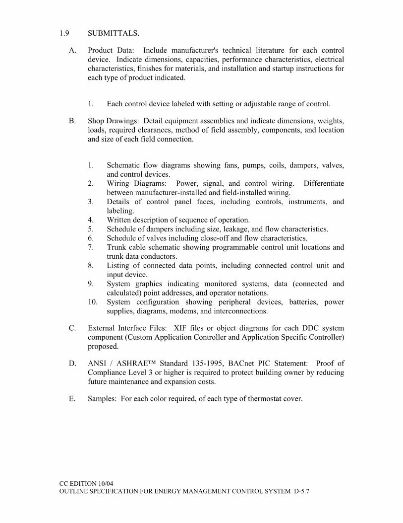
A. Product Data: Include manufacturer's technical literature for each control device. Indicate dimensions, capacities, performance characteristics, electrical characteristics, finishes for materials, and installation and startup instructions for each type of product indicated.
1. Each control device labeled with setting or adjustable range of control.
B. Shop Drawings: Detail equipment assemblies and indicate dimensions, weights, loads, required clearances, method of field assembly, components, and location and size of each field connection.
1. Schematic flow diagrams showing fans, pumps, coils, dampers, valves,
and control devices. 2. Wiring Diagrams: Power, signal, and control wiring. Differentiate
between manufacturer-installed and field-installed wiring. 3. Details of control panel faces, including controls, instruments, and
labeling. 4. Written description of sequence of operation. 5. Schedule of dampers including size, leakage, and flow characteristics. 6. Schedule of valves including close-off and flow characteristics. 7. Trunk cable schematic showing programmable control unit locations and
trunk data conductors. 8. Listing of connected data points, including connected control unit and
input device. 9. System graphics indicating monitored systems, data (connected and
calculated) point addresses, and operator notations. 10. System configuration showing peripheral devices, batteries, power
supplies, diagrams, modems, and interconnections.
C. External Interface Files: XIF files or object diagrams for each DDC system component (Custom Application Controller and Application Specific Controller) proposed.
D. ANSI / ASHRAE™ Standard 135-1995, BACnet PIC Statement: Proof of Compliance Level 3 or higher is required to protect building owner by reducing future maintenance and expansion costs.
E. Samples: For each color required, of each type of thermostat cover.

CC EDITION 10/04 OUTLINE SPECIFICATION FOR ENERGY MANAGEMENT CONTROL SYSTEM D-5.8
F. Software and Firmware Operational Documentation: Include the following:
1. Engineering, Installation, Operation and Maintenance manuals. 2. Program Software Backup: On a magnetic media or compact disc,
complete with data files. 3. Device address list. 4. Printout of software application and graphic screens. 5. Licenses, guarantee, and warranty documents for all equipment and
systems.
G. Field Test Reports: Indicate and interpret test results for compliance with performance requirements.
H. Maintenance Data: For systems to include in maintenance manuals specified in Division 1. Include the following:
I. 1. Maintenance instructions and lists of spare parts for each type of control
device and compressed air station. 2. Interconnection wiring diagrams with identified and numbered system
components and devices. 3. Keyboard illustrations and step-by-step procedures indexed for each
operator function. 4. Inspection period, cleaning methods, cleaning materials recommended,
and calibration tolerances. 5. Calibration records and list of set points.
J. Qualification Data: For firms and persons specified in "Quality Assurance" Article.
K. Project Record Documents: Record actual locations of control components, including control units, thermostats, and sensors. Revise Shop Drawings to reflect actual installation and operating sequences.
1.10 QUALITY ASSURANCE.
A. All work described in this section shall be installed, wired, circuit tested and calibrated by factory certified technicians qualified for this work and in the regular employment of the temperature control system manufacturer's local field office.
B. The Facility Management System contractor shall have a full service facility within 10 miles of the project that is staffed with engineers trained in Integrating Interoperable Systems and technicians fully capable of providing LonWorks instructions and routine emergency maintenance service on all system components.

CC EDITION 10/04 OUTLINE SPECIFICATION FOR ENERGY MANAGEMENT CONTROL SYSTEM D-5.9
C. Mechanical equipment manufacturers that are listed as approved to provide DDC type controls may submit a bid with factory mounted controls, and shall also provide a separate bid for their products less all controls, actuators, valve assemblies and sensors, which are specified to be provided by the FMS contractor.
D. Electrical Components, Devices, and Accessories: Listed and labeled as defined in NFPA 70, Article 100, by a testing agency acceptable to authorities having jurisdiction, and marked for intended use.
E. Comply with NFPA 90A, "Installation of Air Conditioning and Ventilation Systems.".
F. Comply with National Electric Code, UL-916 Energy Management Systems, LonMark™, ULC, FCC Part 15, subpart J, Class B Computing Devices.
G. Comply with EIA Standard 709.1 LonTalk™ protocol for DDC system control components.DELIVERY, STORAGE AND HANDLING.
H. Factory-Mounted Components: Where control devices specified in this Section are indicated to be factory mounted on equipment, arrange for shipping of control devices to unit manufacturer.
I. Provide factory-shipping cartons for each piece of equipment and control device. Maintain cartons through shipping, storage, and handling as required to prevent equipment damage. Store equipment and materials inside and protected from weather.
1.11 COORDINATION.
A. Coordinate location of thermostats, humidistats, and other exposed control sensors with plans and room details before installation.
B. Coordinate equipment from other divisions including "Intrusion Detection," "Lighting Controls,” "Motor Control Centers," "Panelboards," and "Fire Alarm" to achieve compatibility with equipment that interfaces with those systems.
C. Coordinate supply of conditioned electrical circuits for control units and operator workstation.
D. Coordinate location of concrete bases. Cast anchor-bolt inserts into bases. Concrete, reinforcement, and formwork requirements are specified in Division 3 Section "Cast-in-Place Concrete".
E. Coordinate with the Owner's IT department on locations for UNC's, Ethernet communication cabling and TCP/IP addresses.

CC EDITION 10/04 OUTLINE SPECIFICATION FOR ENERGY MANAGEMENT CONTROL SYSTEM D-5.10
1.12 WARRANTY AND MAINTENANCE
A. All components, system software, and parts furnished and installed by the FMS contractor shall be guaranteed against defects in materials and workmanship for 1 year of substantial completion. Labor to repair, reprogram, or replace these components shall be furnished by the FMS contractor at no charge during normal working hours during the warranty period. Materials furnished but not installed by the FMS contractor shall be covered to the extent of the product only. Installation labor shall be the responsibility of the trade contractor performing the installation. All corrective software modifications made during warranty periods shall be updated on all user documentation and on user and manufacturer archived software disks. The Contractor shall respond to the owner's request for warranty service within 24 standard working hours.
1.13 OWNERSHIP OF PROPRIETARY MATERIAL.
A. The owner shall sign a copy of the manufacturer’s standard software and firmware licensing agreement as a condition of this contract. Such license shall grant use of all programs and application software to owner as defined by the manufacturer’s license agreement, but shall protect manufacturer’s rights to disclosure of trade secrets contained within such software. All project developed software and documentation shall become the property of the owner. These include, but are not limited to project graphic images, record drawings, project database, project specific application programming code, and all other associated documentation.

CC EDITION 10/04 OUTLINE SPECIFICATION FOR ENERGY MANAGEMENT CONTROL SYSTEM D-5.11
PART 2 - PRODUCTS
2.1 GENERAL
A. The Facility Management System (FMS) shall be comprised of a network of interoperable, stand-alone digital controllers, a computer system, graphical user interface software, printers, network devices and other devices as specified herein. All systems and software within FMS shall be Year 2000 compliant and shall be supported by compliance documentation from the manufacturer.
B. The installed system shall provide secure password access to all features, functions and data contained in the overall FMS.
2.2 OPEN, INTEROPERABLE, INTEGRATED ARCHITECTURES
A. The intent of this specification is to provide a peer-to-peer networked, stand-alone, distributed control system with the capability to integrate both the ANSI/ASHRAE Standard 135-1995 BACnet, Legacy Systems and LonWorks technology communication protocols in one open, interoperable system.
B. The supplied computer software shall employ object-oriented technology (OOT) for representation of all data and control devices within the system. In addition, adherence to industry standards including ANSI / ASHRAE™ Standard 135-1995, BACnet and LonMark to assure interoperability between all system components is required. For each LonWorks device that does not have LonMark certification, the device supplier must provide an XIF file for the device. For each BACnet device, the device supplier must provide a PICS document showing the installed device’s compliance level. Minimum compliance is Level 3; with the ability to support data read and write functionality. Physical connection of BACnet devices shall be via Ethernet.
C. All components and controllers supplied under this contract shall be true “peer-to-peer” communicating devices. Components or controllers requiring “polling” by a host to pass data shall not be acceptable.
2.3 APPROVED MANUFACTURERS
A. Manufacturers: Subject to compliance with requirements, provide products by one of the following pre-qualified manufacturers:
1. Direct Digital Control Systems and Approved Installing Contractors:
a. Invensys Building Systems I/A Series installed by LONG Building Technologies.
b. Invensys Building Systems I/A Series installed by the owner’s facility construction group.

CC EDITION 10/04 OUTLINE SPECIFICATION FOR ENERGY MANAGEMENT CONTROL SYSTEM D-5.12
2.4 DDC EQUIPMENT
A. Workstation Server Hardware Station: IBM-compatible microcomputer with minimum configuration as follows:
1. Processor: 2-Intel Pentium III, 1.26 GHz., or faster. 2. Random-Access Memory: 2GB ECC SDRAM., minimum. 3. Graphics: Super video graphic adapter (SVGA), minimum 1024 x 768
pixels, 2.0-MB EDO video memory. 4. Monitor: 17 inches (17.4 viewable, minimum), non-interlaced, color, with
maximum 0.28-mm dot pitch. 5. Keyboard: QWERTY, 105 keys in ergonomic shape. 6. Floppy-Disk Drives: 1.44 MB. 7. Hard-Disk Drive: 73GB 10K RPM Ultra 160 SCSI Hard Drive ,
minimum. 8. Embedded Intel PRO/100+ Server Adapter for TCP/IP Communication 9. DVD-ROM Drive: 24X, IDE CD-ROM with software decoding. 10. Mouse: Two button. 11. Operating System: Microsoft Windows XP-Professional. 12. Provide a Printer Dot-matrix type:
a. Print Head: 24 pin, 360 x 360 dpi resolution b. Carriage: Wide, 132 characters per line of paper c. Paper Handling: Fan-fold paper, with 2 cartons containing
minimum of 2500 sheets each and two (2) printer ribbons or cartridges.
d. Print Speed: Minimum of 120 characters per second.
B. Provide Printer Color, ink-jet type:
1. Print Head: 1440 x 1440 dpi photo quality color resolution. 2. Internal Memory Buffer: 32KB. 3. Paper Handling: Minimum of 100 sheets. 4. Print Speed: Minimum of 8 ppm in black and 4 ppm in color.
C. UPS (uninterruptible power supply) shall be installed at the server. Size for 50% spare capacity with sufficient capacity to allow emergency power for a minimum of 10 minutes backup.
D. GUI Server Application Software: Include the following:
Input/output capability from operator station for monitoring and controlling all of the points listed in the input/output point list. The operator shall be able to monitor and access all points by means of clear concise English names without having to understand or reference hardware point locations or controller programs.
CC EDITION 10/04 OUTLINE SPECIFICATION FOR ENERGY MANAGEMENT CONTROL SYSTEM D-5.13
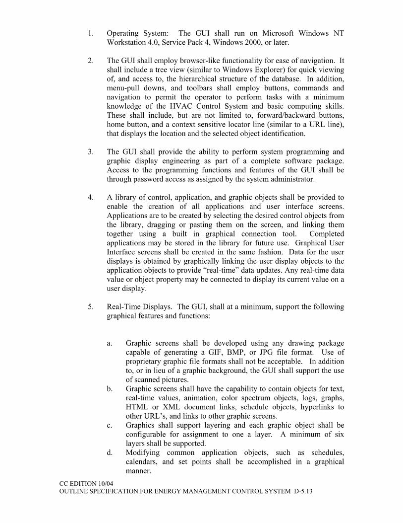
1. Operating System: The GUI shall run on Microsoft Windows NT Workstation 4.0, Service Pack 4, Windows 2000, or later.
2. The GUI shall employ browser-like functionality for ease of navigation. It
shall include a tree view (similar to Windows Explorer) for quick viewing of, and access to, the hierarchical structure of the database. In addition, menu-pull downs, and toolbars shall employ buttons, commands and navigation to permit the operator to perform tasks with a minimum knowledge of the HVAC Control System and basic computing skills. These shall include, but are not limited to, forward/backward buttons, home button, and a context sensitive locator line (similar to a URL line), that displays the location and the selected object identification.
3. The GUI shall provide the ability to perform system programming and
graphic display engineering as part of a complete software package. Access to the programming functions and features of the GUI shall be through password access as assigned by the system administrator.
4. A library of control, application, and graphic objects shall be provided to
enable the creation of all applications and user interface screens. Applications are to be created by selecting the desired control objects from the library, dragging or pasting them on the screen, and linking them together using a built in graphical connection tool. Completed applications may be stored in the library for future use. Graphical User Interface screens shall be created in the same fashion. Data for the user displays is obtained by graphically linking the user display objects to the application objects to provide “real-time” data updates. Any real-time data value or object property may be connected to display its current value on a user display.
5. Real-Time Displays. The GUI, shall at a minimum, support the following
graphical features and functions:
a. Graphic screens shall be developed using any drawing package
capable of generating a GIF, BMP, or JPG file format. Use of proprietary graphic file formats shall not be acceptable. In addition to, or in lieu of a graphic background, the GUI shall support the use of scanned pictures.
b. Graphic screens shall have the capability to contain objects for text, real-time values, animation, color spectrum objects, logs, graphs, HTML or XML document links, schedule objects, hyperlinks to other URL’s, and links to other graphic screens.
c. Graphics shall support layering and each graphic object shall be configurable for assignment to one a layer. A minimum of six layers shall be supported.
d. Modifying common application objects, such as schedules, calendars, and set points shall be accomplished in a graphical manner.
CC EDITION 10/04 OUTLINE SPECIFICATION FOR ENERGY MANAGEMENT CONTROL SYSTEM D-5.14
1) Schedule times will be adjusted using a graphical slider, without requiring any keyboard entry from the operator.
2) Holidays shall be set by using a graphical calendar, without requiring any keyboard entry from the operator.
6. Programming Methods The GUI, shall at a minimum, support the
following programming features and functions:
a. Provide the capability to copy objects from the supplied libraries, or from a user-defined library to the user’s application. Objects shall be linked by a graphical linking scheme by dragging a link from one object to another. Object links will support one-to-one, many-to-one, or one-to-many relationships. Linked objects shall maintain their connections to other objects regardless of where they are positioned on the page and shall show link identification for links to objects on other pages for easy identification. Links will vary in color depending on the type of link; i.e., internal, external, hardware, etc.
b. Configuration of each object will be done through the object’s property sheet using fill-in the blank fields, list boxes, and selection buttons. Use of custom programming, scripting language, or a manufacturer-specific procedural language for configuration will not be accepted.
c. The software shall provide the ability to view the logic in a monitor mode. When on-line, the monitor mode shall provide the ability to view the logic in real time for easy diagnosis of the logic execution. When off-line (debug), the monitor mode shall allow the user to set values to inputs and monitor the logic for diagnosing execution before it is applied to the system.
d. All programming shall be done in real-time. Systems requiring the uploading, editing, and downloading of database objects shall not be allowed.
e. The system shall support object duplication within a customer’s database. An application, once configured, can be copied and pasted for easy re-use and duplication. All links, other than to the hardware, shall be maintained during duplication.
7. Object Libraries The GUI, shall at a minimum, support the following
objects and functions:
a. A standard library of objects shall be included for development and setup of application logic, user interface displays, system services, and communication networks.
b. The objects in this library shall be capable of being copied and pasted into the user’s database and shall be organized according to their function. In addition, the user shall have the capability to group objects created in their application and store the new instances of these objects in a user-defined library.
CC EDITION 10/04 OUTLINE SPECIFICATION FOR ENERGY MANAGEMENT CONTROL SYSTEM D-5.15
c. In addition to the standard libraries specified here, the supplier of the system shall maintain an on-line accessible (over the Internet) library, available to all registered users to provide new or updated objects and applications as they are developed.
d. All control objects shall conform to the control objects specified in the BACnet specification.
e. The library shall include applications or objects for the following functions, at a minimum:
1) Scheduling Object. The schedule must conform to the
schedule object as defined in the BACnet specification, providing 7-day plus holiday & temporary scheduling features and a minimum of 10 on/off events per day. Data entry to be by graphical slider to speed creation and selection of on-off events.
2) Calendar Object. . The calendar must conform to the calendar
object as defined in the BACnet specification, providing 12-month calendar features to allow for holiday or special event data entry. Data entry to be by graphical “point-and-click” selection. This object must be “linkable” to any or all scheduling objects for effective event control
3) Duty Cycling Object. Provide a universal duty cycle object to
allow repetitive on/off time control of equipment as an energy conserving measure. Any number of these objects may be created to control equipment at varying intervals.
4) Temperature Override Object. Provide a temperature override
object that is capable of overriding equipment turned off by other energy saving programs (scheduling, duty cycling etc.) to maintain occupant comfort or for equipment freeze protection.
5) Start-Stop Time Optimization Object. Provide a start-stop
time optimization object to provide the capability of starting equipment just early enough to bring space conditions to desired conditions by the scheduled occupancy time. Also, allow equipment to be stopped before the scheduled un-occupancy time just far enough ahead to take advantage of the building’s “flywheel” effect for energy savings. Provide automatic tuning of all start / stop time object properties based on the previous day’s performance.

CC EDITION 10/04 OUTLINE SPECIFICATION FOR ENERGY MANAGEMENT CONTROL SYSTEM D-5.16
6) Demand Limiting Object. Provide a comprehensive demand-limiting object that is capable of controlling demand for any selected energy utility (electric, oil, and gas). The object shall provide the capability of monitoring a demand value and predicting (by use of a sliding window prediction algorithm) the demand at the end of the user defined interval period (1-60 minutes). This object shall also accommodate a utility meter time sync pulse for fixed interval demand control. Upon a prediction that will exceed the user defined demand limit (supply a minimum of 6 per day), the demand limiting object shall issue shed commands to either turn off user specified loads or modify equipment set points to effect the desired energy reduction. If the list of sheddable equipment is not enough to reduce the demand to below the set point, a message shall be displayed on the users screen (as an alarm) instructing the user to take manual actions to maintain the desired demand. The shed lists are specified by the user and shall be selectable to be shed in either a fixed or rotating order to control which equipment is shed the most often. Upon suitable reductions in demand, the demand-limiting object shall restore the equipment that was shed in the reverse order in which it was shed. Each sheddable object shall have a minimum and maximum shed time property to effect both equipment protection and occupant comfort.
f. The library shall include control objects for the following functions. All control objects shall conform to the objects as specified in the BACnet specification.
1) Analog Input Object - Minimum requirement is to comply
with the BACnet standard for data sharing. Allow high, low and failure limits to be assigned for alarming. Also, provide a time delay filter property to prevent nuisance alarms caused by temporary excursions above or below the user defined alarm limits.
2) Analog Output Object - Minimum requirement is to comply
with the BACnet standard for data sharing.
3) Binary Input Object - Minimum requirement is to comply with
the BACnet standard for data sharing. The user must be able to specify either input condition for alarming. This object must also include the capability to record equipment run-time by counting the amount of time the hardware input is in an “on” condition. The user must be able to specify either input condition as the “on” condition.

CC EDITION 10/04 OUTLINE SPECIFICATION FOR ENERGY MANAGEMENT CONTROL SYSTEM D-5.17
4) Binary Output Object - Minimum requirement is to comply with the BACnet standard for data sharing. Properties to enable minimum on and off times for equipment protection as well as interstart delay must be provided. The BACnet Command Prioritization priority scheme shall be incorporated to allow multiple control applications to execute commands on this object with the highest priority command being invoked. Provide sixteen levels of priority as a minimum. Systems not employing the BACnet method of contention resolution shall not be acceptable.
5) PID Control Loop Object - Minimum requirement is to
comply with the BACnet standard for data sharing. Each individual property must be adjustable as well as to be disabled to allow proportional control only, or proportional with integral control, as well as proportional, integral and derivative control.
6) Comparison Object - Allow a minimum of two analog objects
to be compared to select either the highest, lowest, or equality between the two linked inputs. Also, allow limits to be applied to the output value for alarm generation.
7) Math Object - Allow a minimum of four analog objects to be
tested for the minimum or maximum, or the sum, difference, or average of linked objects. Also, allow limits to be applied to the output value for alarm generation.
8) Custom Programming Objects - Provide a blank object
template for the creation of new custom objects to meet specific user application requirements. This object must provide a simple BASIC-like programming language that is used to define object behavior. Provide a library of functions including math and logic functions, string manipulation, and e-mail as a minimum. Also, provide a comprehensive on-line debug tool to allow complete testing of the new object. Allow new objects to be stored in the library for re-use

CC EDITION 10/04 OUTLINE SPECIFICATION FOR ENERGY MANAGEMENT CONTROL SYSTEM D-5.18
9) Interlock Object - Provide an interlock object that provides a means of coordination of objects within a piece of equipment such as an Air Handler or other similar types of equipment. An example is to link the return fan to the supply fan such that when the supply fan is started, the return fan object is also started automatically without the user having to issue separate commands or to link each object to a schedule object. In addition, the control loops, damper objects, and alarm monitoring (such as return air, supply air, and mixed air temperature objects) will be inhibited from alarming during a user-defined period after startup to allow for stabilization. When the air handler is stopped, the interlocked return fan is also stopped, the outside air damper is closed, and other related objects within the air handler unit are inhibited from alarming thereby eliminating nuisance alarms during the off period.
10) Temperature Override Object - Provide an object whose
purpose is to provide the capability of overriding a binary output to an “On” state in the event a user specified high or low limit value is exceeded. This object is to be linked to the desired binary output object as well as to an analog object for temperature monitoring, to cause the override to be enabled. This object will execute a Start command at the Temperature Override level of start/stop command priority unless changed by the user.
11) Composite Object - Provide a container object that allows a
collection of objects representing an application to be encapsulated to protect the application from tampering, or to more easily represent large applications. This object must have the ability to allow the user to select the appropriate parameters of the “contained” application that are represented on the graphical shell of this container.
g. The object library shall include objects to support the integration of
devices connected to the Universal Network Controller (UNC). At a minimum, provide the following as part of the standard library included with the programming software:
1) LonMark/LonWorks devices. These devices shall include, but
not be limited to, devices for control of HVAC, lighting, access, and metering. Provide LonMark manufacturer-specific objects to facilitate simple integration of these devices. All network variables defined in the LonMark profile shall be supported. Information (type and function) regarding network variables not defined in the LonMark profile shall be provided by the device manufacturer.

CC EDITION 10/04 OUTLINE SPECIFICATION FOR ENERGY MANAGEMENT CONTROL SYSTEM D-5.19
2) For devices not conforming to the LonMark standard, provide a dynamic object that can be assigned to the device based on network variable information provided by the device manufacturer. Device manufacturer shall provide an XIF file and documentation for the device to facilitate device integration.
3) For BACnet devices, provide the following objects at a
minimum: a) BACnet AI b) BACnet AO c) BACnet BI d) BACnet BO e) BACnet Device
4) For each BACnet object, provide the ability to assign the object a BACnet device and object instance number.
8. Commands to start and stop binary objects shall be done by right-clicking
the selected object and selecting the appropriate command from the pop-up menu. No entry of text shall be required.
9. Adjustments to analog objects, such as set points, shall be done by right-
clicking the selected object and using a graphical slider to adjust the value. No entry of text shall be required.
10. System Configuration. At a minimum, the GUI shall permit the operator to
perform the following tasks, with proper password access: a. Create, delete or modify control strategies. b. Add/delete objects to the system. c. Tune control loops through the adjustment of control loop
parameters. d. Enable or disable control strategies. e. Generate hard copy records or control strategies on a printer. f. Select points to be alarmable and define the alarm state. g. Select points to be trended over a period of time and initiate the
recording of values automatically.
11. On-Line Help. Provide a context sensitive, on-line help system to assist the operator in operation and editing of the system. On-line help shall be available for all applications and shall provide the relevant data for that particular screen. Additional help information shall be available through the use of hypertext. All system documentation and help files shall be in HTML format.

CC EDITION 10/04 OUTLINE SPECIFICATION FOR ENERGY MANAGEMENT CONTROL SYSTEM D-5.20
12. On-Line Operation & Maintenance Documentation. An electronic copy of the DDC system operation and maintenance manual and the “As-Built” control drawings in PDF format shall be installed on the Facilities Graphics Server located in the Central heating Plant. The O&M information shall be accessed through an additional menu link at the Facilities Graphics Server. The menu link for the O&M information shall be associated with the building the DDC controls have been installed at.
13. Security. Each operator shall be required to log on to that system with a
user name and password in order to view, edit, add, or delete data. System security shall be selectable for each operator. The system administrator shall have the ability to set passwords and security levels for all other operators. Each operator password shall be able to restrict the operators’ access for viewing and/or changing each system application, full screen editor, and object. Each operator shall automatically be logged off of the system if no keyboard or mouse activity is detected. This auto log-off time shall be set per operator password. All system security data shall be stored in an encrypted format.
14. System Diagnostics. The system shall automatically monitor the operation
of all workstations, printers, modems, network connections, building management panels, and controllers. The failure of any device shall be annunciated to the operator.
15. Alarm Console
a. The system will be provided with a dedicated alarm window or console. This window will notify the operator of an alarm condition, and allow the operator to view details of the alarm and acknowledge the alarm. The use of the Alarm Console can be enabled or disabled by the system administrator.
b. When the Alarm Console is enabled, a separate alarm notification window will supercede all other windows on the desktop and shall not be capable of being minimized or closed by the operator. This window will notify the operator of new alarms and un-acknowledged alarms. Alarm notification windows or banners that can be minimized or closed by the operator shall not be acceptable.
16. DDE Device Integration
a. The Universal Network Controller shall support the integration of device data via Dynamic Data Exchange (DDE), over the Ethernet Network. The Universal Network Controller shall act as a DDE client to another software application that functions as a DDE server.

CC EDITION 10/04 OUTLINE SPECIFICATION FOR ENERGY MANAGEMENT CONTROL SYSTEM D-5.21
b. Provide the required objects in the library, included with the Graphical User Interface programming software, to support the integration of these devices into the FMS. Objects provided shall include at a minimum:
1) DDE Generic AI Object 2) DDE Generic AO Object 3) DDE Generic BO Object 4) DDE Generic BI Object
17. Legacy System Integration
a. The Universal Network Controller shall support the integration of device data from the existing control system. The connection to the existing system shall be via an RS-485 connection between the Universal Network Controller and the existing control system.
b. The owner, and/or the legacy control system representative shall ensure that the existing system’s database is setup to make all data to be integrated into the FMS available at the RS-485 port. Any modifications to the existing system database to accomplish this shall be the responsibility of the owner.
c. Provide the required objects in the library, included with the Graphical User Interface programming software, to support the integration of the existing system data into the FMS. Objects provided shall include at a minimum:
1) LEGACY SYSTEM Generic AI Object 2) LEGACY SYSTEM Generic AO Object 3) LEGACY SYSTEM Generic BO Object 4) LEGACY SYSTEM Generic BI Object
d. All scheduling, alarming, logging and global supervisory control functions (demand limiting, etc.), of the existing system devices, shall be performed by the Network Area Controller. Integration of the existing system’s schedules, alarms, logs, etc. is neither required nor desired.
e. The FMS supplier shall provide a legacy system communications driver.
E. Web Browser Clients
1. The system shall be capable of supporting 64 clients using a standard Web
browser such as Internet Explorer™ or Netscape Navigator™. Systems requiring additional software (to enable a standard Web browser) to be resident on the client machine, are only acceptable if 64 licensed copies of the client machine software are provided, installed, and tested.

CC EDITION 10/04 OUTLINE SPECIFICATION FOR ENERGY MANAGEMENT CONTROL SYSTEM D-5.22
2. The Web browser software shall run on any operating system and system configuration that is supported by the Web browser. Systems that require specific machine requirements in terms of processor speed, memory, etc., in order to allow the Web browser to function with the FMCS, shall only be acceptable if 64 workstations or workstation hardware upgrades are provided.
3. The Web browser shall provide the same view of the system, in terms of
graphics, schedules, calendars, logs, etc., and provide the same interface methodology as is provided by the Graphical User Interface. Systems that require different views or that require different means of interacting with objects such as schedules, or logs, shall not be permitted.
4. The Web browser client shall support at a minimum, the following
functions: 5.
a. User log-on identification and password shall be required. If an unauthorized user attempts access, a blank web page shall be displayed. Security using Java authentication and encryption techniques to prevent unauthorized access shall be implemented.
b. Graphical screens developed for the GUI shall be the same screens used for the Web browser client. Any animated graphical objects supported by the GUI shall be supported by the Web browser interface.
c. HTML programming shall not be required to display system graphics or data on a Web page. HTML editing of the Web page shall be allowed if the user desires a specific look or format.
d. Storage of the graphical screens shall be in the Building Control Units (BC), without requiring any graphics to be stored on the client machine. Systems that require graphics storage on each client are not acceptable.
e. Real-time values displayed on a Web page shall update automatically without requiring a manual “refresh” of the Web page.
f. User’s shall have administrator-defined access privileges. Depending on the access privileges assigned, the user shall be able to perform the following:
1) Modify common application objects, such as schedules, calendars, and set points in a graphical manner. a) Schedule times will be adjusted using a graphical slider,
without requiring any keyboard entry from the operator. b) Holidays shall be set by using a graphical calendar,
without requiring any keyboard entry from the operator.
2) Commands to start and stop binary objects shall be done by right-clicking the selected object and selecting the appropriate command from the pop-up menu. No entry of text shall be required.

CC EDITION 10/04 OUTLINE SPECIFICATION FOR ENERGY MANAGEMENT CONTROL SYSTEM D-5.23
3) View logs and charts
4) View and acknowledge alarms
g. The system shall provide the capability to specify a user’s (as
determined by the log-on user identification) home page. Provide the ability to limit a specific user to just their defined home page. From the home page, links to other views, or pages in the system shall be possible, if allowed by the system administrator.
h. Graphic screens on the Web Browser client shall support hypertext links to other locations on the Internet or on Intranet sites, by specifying the Uniform Resource Locator (URL) for the desired link.
F. Portable Engineering Stations
1. Provide a Portable Engineering Station (PES) color display personal
computer, software, and interfaces to provide; uploading/downloading of Custom Application Controller and Application Specific Controllers databases, monitoring of all LonMark™ Standard Network Variables Types (SNVTs) including display of all bound SNVTs, monitoring and overrides of all controller physical input/output points, and editing of controller resident time schedules. PES connectivity shall be via digital wall sensor connected to controller.
2. The Portable Engineering Station shall use Visio and all programming shall be graphical.
3. The Portable Engineering Station shall be able to access any other controller on that segment of the LAN
4. Connection of a PES to the Custom Application Controller or Application Specific Controller shall not interfere with normal network operation in any way, prevent alarms from being transmitted or centrally initiated commands from being executed.
5. If the PES cannot be used for both the CAC’s and ASC’s, provide, in addition to the PES, the separate color display personal computer(s), software, and interfaces required to provide full PES functionality for both the CAC’s and ASC’s.
6. Hardware for the PES shall consist of the following:
a. Pentium III processor b. Large 15” UXGA active matrix (TFT) display c. 256 MB 133 MHz SDRAM memory d. 60 GB internal hard drive e. Ethernet 10/100 Mb NIC f. Integrated 56 Kbps modem g. PCMCIA LON Card
CC EDITION 10/04 OUTLINE SPECIFICATION FOR ENERGY MANAGEMENT CONTROL SYSTEM D-5.24
7. Functionality of the PES connected to any CAC or ASC shall include:
a. Uploads and downloads of CAC and ASC Controller databases. b. Uploads and downloads of CAC and ASC LonMark™ SNVT nci
values. c. Editing of LonMark™ SNVT nci values for minor equipment
operational parameters (including minimum on/off and delay times, changeover values, minimum position setpoints, etc.). All such mechanical equipment editable nci values shall contain internal CAC and ASC Controller safety range limits to prevent accidental entry of out of range or invalid values.
d. Monitoring of all LonMark™ Standard Network Variables Types (SNVTs) including display of all bound SNVTs and test overrides of nvi SNVTs.
e. Monitoring and overrides of all controller physical input/output points including timed overrides that automatically revert back to their normal value.
f. Display of digital sensor values including diagnostics and calibration.
g. Editing of controller time/date. h. Editing and overrides of resident Controller time schedules. i. LonMark™ information including program ID, Neuron ID, domain,
subnet, and node.
G. Portable Operator’s Terminal
1. Provide a Portable Operator’s Terminal (POT) color display personal
computer, software, and interfaces to provide; uploading/downloading of Custom Application Controller and Application Specific Controllers databases, monitoring of all LonMark™ Standard Network Variables Types (SNVTs) including display of all bound SNVTs, monitoring and overrides of all controller physical input/output points, and editing of controller resident time schedules. POT connectivity shall be via digital wall sensor connected to controller.
2. Connection of a POT to the Custom Application Controller or Application
Specific Controller shall not interfere with normal network operation in any way, prevent alarms from being transmitted or centrally initiated commands from being executed.
3. If the POT cannot be used for both the CAC’s and ASC’s, provide, in
addition to the POT, the separate color display personal computer(s), software, and interfaces required to provide full POT functionality for both the CAC’s and ASC’s.

CC EDITION 10/04 OUTLINE SPECIFICATION FOR ENERGY MANAGEMENT CONTROL SYSTEM D-5.25
4. Functionality of the POT connected to any CAC or ASC shall include:
a. Uploads and downloads of CAC and ASC Controller databases. b. Uploads and downloads of CAC and ASC LonMark™ SNVT nci
values. c. Editing of LonMark™ SNVT nci values for minor equipment
operational parameters (including minimum on/off and delay times, changeover values, minimum position setpoints, etc.). All such mechanical equipment editable nci values shall contain internal CAC and ASC Controller safety range limits to prevent accidental entry of out of range or invalid values.
d. Monitoring of all LonMark™ Standard Network Variables Types (SNVTs) including display of all bound SNVTs and test overrides of nvi SNVTs.
e. Monitoring and overrides of all controller physical input/output points including timed overrides that automatically revert back to their normal value.
f. Display of digital sensor values including diagnostics and calibration.
g. Editing of controller time/date. h. Editing and overrides of resident Controller time schedules. i. LonMark™ information including program ID, Neuron ID, domain,
subnet, and node.
H. Control Units General:
Provide an adequate number of control units to achieve monitoring and control of all data points specified and necessary to satisfy the sequence of operation for all mechanical systems shown on the plans. Provide a minimum of one separate controller for each AHU or other HVAC system. Multiple DDC controllers may control one system provided that all points associated with individual control loops are assigned to the same DDC controller. Points used for control loop reset such as outside air or space temperature are exempt from this requirement. Each of the following panel types shall meet the following requirements.
1. Controllers shall be suitable for the anticipated ambient conditions.
a. Controllers used outdoors and/or in wet ambient conditions shall be mounted within waterproof enclosures, and shall be rated for operation at -40°F to 140°F and 5 to 95% RH, non-condensing.
b. Controllers used in conditioned ambient space shall be mounted in dustproof enclosures, and shall be rated for operation at 32°F to 122°F and 5 to 95% RH, non-condensing.

CC EDITION 10/04 OUTLINE SPECIFICATION FOR ENERGY MANAGEMENT CONTROL SYSTEM D-5.26
2. Serviceability: Provide diagnostic LEDs for power, communication, and processor. All wiring connections shall be made to field-removable, modular terminal strips or to a termination card connected by a ribbon cable.
3. Memory: The Control Units shall maintain all BIOS and programming
information in the event of a power loss for at least 72 hours.
4. Diagnostics: The Building Controller shall continually check the status of
its processor and memory circuits. If an abnormal operation is detected, the controller shall assume a predetermined failure mode and generate an alarm notification.
5. Immunity to power and noise: Controller shall be able to operate at 90%
to 110% of nominal voltage rating and shall perform an orderly shutdown below 80% nominal voltage. Operation shall be protected against electrical noise of 5 to 120 Hz and from keyed radios up to 5 W at 3 ft.
6. Automatic staggered restart of field equipment after restoration of power
and short cycle protection.
I. Universal Network Controllers (UNC)
1. The Universal Network Controllers (UNC) shall provide the interface
between the LAN and the field control devices, and provide global supervisory control functions over the control devices connected to the UNC. It shall be capable of executing application control programs to provide:
a. Calendar functions b. Scheduling c. Trending d. Alarm monitoring and routing e. Time synchronization by means of an Atomic Clock Internet site
including automatic synchronization f. Integration of LonWorks controller data, Legacy MicroSmart
controller data and BACnet controller data g. Network Management functions for all LonWorks based devices

CC EDITION 10/04 OUTLINE SPECIFICATION FOR ENERGY MANAGEMENT CONTROL SYSTEM D-5.27
2. The Universal Network Controller (UNC) must provide the following hardware features as a minimum:
a. One Ethernet Port – 10/100 Mbps b. Two RS-232 ports c. Two RS-RS485 ports electrically isolated d. One LonWorks Interface Port – 78KB FTT-10A with Weidmuller
connector e. Power supply 24 VAC or 24 VDC f. Battery Backup g. Real-time clock h. Processor @ 200 MHz or greater i. Java Virtual Machine j. 40 Mb flash memory for long term data backup (If battery backup or
flash memory is not supplied, the controller must contain a hard disk with at least 1 gigabyte storage capacity)
k. 128 Mb Ram or greater
3. The UNC shall provide multiple user access to the system and support for ODBC or SQL. A database resident on the UNC shall be an ODBC compliant database or must provide an ODBC data access mechanism to read and write data stored within it.
4. The UNC shall support standard Web browser access via the
Intranet/Internet. It shall support a minimum of 64 simultaneous users. 5. Event Alarm Notification and actions
a. The UNC shall provide alarm recognition, storage; routing, management, and analysis to supplement distributed capabilities of equipment or application specific controllers.
b. The UNC shall be able to route any alarm condition to any defined user location whether connected to a local network or remote via dial-up telephone connection, or wide-area network.
c. Alarm generation shall be selectable for annunciation type and acknowledgement requirements including but limited to:
1) To alarm
2) Return to normal
3) To fault
d. Provide for the creation of a minimum of eight of alarm classes for
the purpose of routing types and or classes of alarms, i.e.: security, HVAC, Fire, etc.
e. Provide timed (schedule) routing of alarms by class, object, group, or node.

CC EDITION 10/04 OUTLINE SPECIFICATION FOR ENERGY MANAGEMENT CONTROL SYSTEM D-5.28
f. Provide alarm generation from binary object “runtime” and /or event counts for equipment maintenance. The user shall be able to reset runtime or event count values with appropriate password control.
g. Control equipment and network failures shall be treated as alarms and annunciated.
h. Alarms shall be annunciated in any of the following manners as
defined by the user:
1) Screen message text
2) Email of the complete alarm message to multiple recipients. Provide the ability to route and email alarms based on:
a) Day of week b) Time of day c) Recipient
3) Pagers via paging services that initiate a page on receipt of email message
4) Graphic with flashing alarm object(s)
5) Printed message, routed directly to a dedicated alarm printer
i. The following shall be recorded by the UNC for each alarm (at a
minimum):
1) Time and date
2) Location (building, floor, zone, office number, etc.)
3) Equipment (air handler #, accessway, etc.)
4) Acknowledge time, date, and user who issued acknowledgement.
5) Number of occurrences since last acknowledgement.
j. Alarm actions may be initiated by user defined programmable
objects created for that purpose. k. Defined users shall be given proper access to acknowledge any
alarm, or specific types or classes of alarms defined by the user.
l. A log of all alarms shall be maintained by the UNC and/or a server
(if configured in the system) and shall be available for review by the user.
m. Provide a “query” feature to allow review of specific alarms by user
defined parameters.

CC EDITION 10/04 OUTLINE SPECIFICATION FOR ENERGY MANAGEMENT CONTROL SYSTEM D-5.29
n. A separate log for system alerts (controller failures, network failures, etc.) shall be provided and available for review by the user.
o. An Error Log to record invalid property changes or commands shall
be provided and available for review by the user.
6. Data Collection and Storage
a. The UNC shall have the ability to collect data for any property of any object and store this data for future use.
b. The data collection shall be performed by log objects, resident in the
UNC that shall have, at a minimum, the following configurable properties:
1) Designating the log as interval or deviation.
2) For interval logs, the object shall be configured for time of day, day of week and the sample collection interval.
3) For deviation logs, the object shall be configured for the deviation of a variable to a fixed value. This value, when reached, will initiate logging of the object.
4) For all logs, provide the ability to set the maximum number of data stores for the log and to set whether the log will stop collecting when full, or rollover the data on a first-in, first-out basis.
5) Each log shall have the ability to have its data cleared on a time-based event or by a user-defined event or action.
7. All log data shall be stored in a relational database in the UNC and the
data shall be accessed from a server (if the system is so configured) or a standard Web Browser.
8. All log data, when accessed from a server, shall be capable of being
manipulated using standard SQL statements.
9. All log data shall be available to the user in the following data formats:
a. HTML b. XML c. Plain Text d. Comma or tab separated values
10. Systems that do not provide log data in HTML and XML formats at a minimum shall provide as an alternative Microsoft SQL Serverâ, Oracle 8i or Expressâ, Hyperion Solutions™ SQL Server.

CC EDITION 10/04 OUTLINE SPECIFICATION FOR ENERGY MANAGEMENT CONTROL SYSTEM D-5.30
11. The UNC shall have the ability to archive it’s log data either locally (to itself), or remotely to a server or other UNC on the network. Provide the ability to configure the following archiving properties, at a minimum:
a. Archive on time of day b. Archive on user-defined number of data stores in the log (buffer
size) c. Archive when log has reached it’s user-defined capacity of data
stores d. Provide ability to clear logs once archived
12. AUDIT LOG
a. Provide and maintain an Audit Log that tracks all activities performed on the UNC. Provide the ability to specify a buffer size for the log and the ability to archive log based on time or when the log has reached it’s user-defined buffer size. Provide the ability to archive the log locally (to the UNC), to another UNC on the network, or to a server. For each log entry, provide the following data:
1) Time and date
2) User ID
3) Change or activity: i.e., Change setpoint, add or delete objects, commands, etc.
13. DATABASE BACKUP AND STORAGE
a. The UNC shall have the ability to automatically backup its database. The database shall be backed up based on a user-defined time interval.
b. Copies of the current database and, at the most recently saved database shall be stored in the UNC. The age of the most recently saved database is dependent on the user-defined database save interval.
c. The UNC database shall be stored, at a minimum, in XML format to allow for user viewing and editing, if desired. Other formats are acceptable as well, as long as XML format is supported.
J. Custom Application Control Units:
Modular, comprising processor board with programmable, nonvolatile, RAM/EEPROM memory for custom control applications. CAC’s shall be provided for Roof Top Units, Boiler Plant, Chiller Plant and other applications as shown on drawings and shall have published Lon-Works™ application source code, device resource files and external interface definitions

CC EDITION 10/04 OUTLINE SPECIFICATION FOR ENERGY MANAGEMENT CONTROL SYSTEM D-5.31
1. Units monitor or control each input/output point; process information; and at least 50 expressions for customized HVAC control including mathematical equations, Boolean logic, PID control loops with anti-windup, sequencers, timers, interlocks, thermostats, enthalpy calculation, counters, interlocks, ramps, drivers, schedules, calendars, OSS, compare, limit, curve fit, and alarms.
2. Stand-alone mode control functions operate regardless of network status.
Functions include the following:
a. Peer to peer primary network level communications supporting at least 200 LonMark™ Standard Network Variables (SNVTs) per CAC utilizing at least 100 different SNVT types as documented by the LonMark™ Interoperability Association to assure present and future compatibility with third party LonMark™ devices. The 200 LonMark™ SNVTs, minimum, must be configurable in any combination – all inputs or all outputs or any combination of input/outputs in any combination of the 100 different, minimum, SNVT types. The XIF SNVT order shall be definable, rather than random, to provide logical and effective LonMark™ network management. With the submittal package, contractor shall provide CAC performance data that specifies the exact maximum number of SNVTs available in any combination and a list of all available SNVT types including the LonMark™ Interoperability Association SNVT number.
b. Automatic communications loss detection to maintain normal
control functionality regardless of available network communications.
c. Discrete/digital, analog, and pulse input/outputs. d. Monitoring, controlling, or addressing data points. e. Local energy management control strategies f. Incorporate internal customizable safeties and limits to prevent third
party LonMark™ tools from providing improper and unrealistic inputs to CAC‘s.
3. Local operator interface port provides for download from and connection
to portable workstation. 4. Communication: The Custom Application Controller shall communicate
via the Primary Controller Network between FMS Controllers and other LonWorks™ devices. CAC’s shall communicate with the Building Controller and ASC’s at a baud rate of not less than 78.8K baud using LonTalk™ communications protocol (EIA 709.1).

CC EDITION 10/04 OUTLINE SPECIFICATION FOR ENERGY MANAGEMENT CONTROL SYSTEM D-5.32
K. Application Specific Control Units:
Single board construction comprising processor board with programmable, nonvolatile, RAM/EEPROM memory for custom control and unitary applications. ASCs shall be provided for Unit Ventilators, Fan Coils, Heat Pumps, Rooftop Units, and other applications as shown on the drawings. To assure complete interoperability, all ASCs firmware shall support all mandatory and all optional LonMark™ Standard Network Variables (SNVTs) for their LonMark™ profile as documented by the LonMark™ Interoperability Association. Bidder shall provide proof of ASC compliance for all the mandatory and all optional LonMark™ SNVTs. ASCs shall be based on the Echelon Neuron 3150 microprocessor working with the ASCs stand alone control program.
1. Units monitor or control each input/output point; process information; and
download from the operator station. 2. Stand-alone mode control functions operate regardless of network status.
Functions include the following:
a. Peer to peer primary network level communications with automatic
communications loss detection to maintain normal control functionality regardless of available network communications.
b. Discrete/digital, analog, and pulse input/output.
c. Monitoring, controlling, or addressing data points. d. Appropriate LonMark™ profiles for specific unitary applications.
e. Support for all mandatory and optional LonMark™ Standard
Network Variable Types (SNVTs) for their LonMark™ profile as documented by the LonMark™ Interoperability Association
f. Internal customizable safeties and limits to prevent third party
LonMark™ tools from providing improper and unrealistic inputs to ASC’s.
3. Local operator interface port located on ASC and ASC sensor provides for download from or upload to portable workstation. All Lon bus devices shall be accessible from either port.

CC EDITION 10/04 OUTLINE SPECIFICATION FOR ENERGY MANAGEMENT CONTROL SYSTEM D-5.33
4. Communication: ASC’s shall communicate with the Building Controller and CAC’s at a baud rate of not less than 78.8K baud using LonTalk™ communications protocol (EIA 709.1).
5. ASC units monitor or control each input/output point; process
information; and at least 50 expressions for customized HVAC control including mathematical equations, Boolean logic, PID control loops with anti-windup, sequencers, timers, interlocks, thermostats, counters, interlocks, compare, limit, and alarms.
6. All ASC Controller setpoints shall be digital display setpoints with dual
setpoint limits (integral hard limits which the user cannot exceed above and below and independent soft limits which are hidden from the user). All digital setpoints shall be network retentive after power outages and after replacement of sensor.
L. ASC Room Sensor
1. The ASC Sensor shall provide room temperature value to the ASC. 2. The ASC Sensor shall connect directly to the ASC and shall not utilize
any of the I/O points of the controller. 3. The ASC Sensor shall provide a two-wire connection to the controller that
is polarity and wire type insensitive. 4. The ASC Sensor shall provide a communications jack for connection to
the LON communication trunk to which the ASC controller is connected. 5. The ASC Sensor, the connected controller, and all other devices on the
LON bus shall be accessible by the Portable Engineering Station. 6. The ASC Sensor shall be provided in a modular configuration that allows
for the rough in of all wiring without the presence of the electronics or esthetic covering.
7. The ASC Sensor shall allow for the customization of the color on the esthetic covering as a standard offering.
8. The ASC Sensor shall be supplied in the following manner:
a. LCD display for showing (typically) the current temperature. b. Tenant override to allow timed override of unoccupied to occupied
mode of operation. c. LED indication of override state d. Up/Down keys to allow adjustment of the current setpoint e. User interface with the ASC Sensor shall be provided as a
configurable function, and shall offer password protection for access to network variable editing.

CC EDITION 10/04 OUTLINE SPECIFICATION FOR ENERGY MANAGEMENT CONTROL SYSTEM D-5.34
f. ASHRAE 95 compliance (LCD display and sub-base functionality) g. The room sensor shall provide access to additional diagnostic data
from a sensor-user keypad request. This Diagnostic mode is displayed on the LCD screens and includes separate displays for the controllers:
1) Subnet and Node Address
2) Errors
3) Alarms
4) Temperature Offset
M. ASC – VAV Controller Functionality.
Controls shall be microprocessor based Pressure Independent Variable Air Volume Digital Controllers, as shown in the drawings. The VAV ASC shall be a single integrated package consisting of a microprocessor, power supply, damper actuator, differential pressure transducer, field terminations, and application software. An alternate model shall be offered that allows for direct connectivity to an external actuator for those applications that employ a non-butterfly style damper configuration. All input/output signals shall be directly hardwired to the VAV ASC controller. The internal actuator shall employ a manual override that allows for powered or non-powered adjustment of the damper position. In all cases, the controller shall automatically resume proper operation following the return of power to, or control by the ASC. Programming, configuring and/or troubleshooting of input/output signals shall be easily executed through the ASC sensor or GP tool connected at the wall sensor location.
1. LonMark™ VAV profiles for including support for all mandatory and
optional LonMark™ Standard Network Variable Types (SNVTs) as documented by the LonMark™ Interoperability Association
2. The VAV ASC control algorithms shall be designed to limit the frequency
of damper repositioning, to assure a minimum 10-year life from all components. The VAV ASC shall provide internal differential pressure transducer for pressure independent applications with an accuracy of ± 5 %. Flow through transducers requiring filter maintenance are not acceptable. The VAV ASC shall provide zone control accuracy equal to or better than +/- 1 degree F. Systems providing control accuracies greater than +/- 1 degree F are not acceptable. With the submittal package, contractor shall provide performance data that verifies control accuracy of the VAV ASC.

CC EDITION 10/04 OUTLINE SPECIFICATION FOR ENERGY MANAGEMENT CONTROL SYSTEM D-5.35
3. All input/output signals shall be directly hardwired to the VAV ASC. A minimum of one input point of the VAV ASC shall employ a universal configuration that allows for flexibility in application ranging from dry contact, resistive, to voltage/current sourced inputs. If a universal point is not available, a minimum of one input point (each) of the dry contact, resistive and analog voltage/current types must be provided on every controller. The outputs of the ASC shall be of the relay and universal analog form. All digital outputs shall be relay type. ASC devices utilizing non-relay outputs shall provide an interface relay for all points. All analog outputs shall be programmable for their start points and span to accommodate the control devices. Configuration of all I/O points shall be accomplished without physical hardware jumpers, switches or settings. Troubleshooting of input/output signals shall be easily executed with the Graphical Programming tool or a volt-ohm meter (VOM). All I/O points shall be utilized by the local ASC or shall be available as I/O points for other controllers throughout the network.
4. The FMCS contractor shall provide VAV ASC to the VAV box
manufacturer, for factory mounting. The VAV terminal unit supplier shall include in its price all costs for mounting of VAV ASC controller, connection of actuator to damper shaft, wiring of device power, wiring of VAV ASC to fan (fan powered terminal) and wiring to electric reheat coils or reheat valve actuator as specified on drawing.
5. The VAV terminal manufacturer shall provide a multi-point, averaging,
differential pressure sensor mounted on the inlet to each VAV box. The VAV terminal unit manufacturer shall supply a line to low voltage transformer, of sufficient capacity, to power the VAV ASC plus all reheat valves and/or contactors and fan circuits associated with the VAV terminal and actuator assemblies. The FMCS contractor shall provide all reheat control valves to the mechanical contractor for mounting and piping. The FMCS contractor shall provide and install all wiring between the valve and VAV ASC controller and between the room sensor and the VAV ASC controller.
N. VAV Box Room Sensor
1. The VAV Box Room Sensor shall provide room temperature value to the
controller. 2. The VAV Box Room Sensor shall connect directly to the controller Box
and shall not utilize any of the I/O points of the controller. 3. The VAV Box Room Sensor shall provide a two-wire connection to the
controller that is polarity and wire type insensitive. 4. The VAV Box Room Sensor shall provide a communications jack for
connection to the LON communication trunk to which the ASC controller is connected.
CC EDITION 10/04 OUTLINE SPECIFICATION FOR ENERGY MANAGEMENT CONTROL SYSTEM D-5.36
5. The VAV Box Room Sensor, the connected controller, and all other devices on the LON bus shall be accessible by the Portable Engineering Station.
6. The VAV Box Room Sensor shall be provided in a modular configuration that allows for the rough in of all wiring without the presence of the electronics or esthetic covering.
7. The VAV Box Room Sensor shall allow for the customization of the color on the esthetic covering as a standard offering.
8. The VAV Box Room Sensor shall be supplied in the following manner: a. LCD display for showing (typically) the current temperature. b. Tenant override to allow timed override of unoccupied to occupied
mode of operation. c. LED indication of override state d. Up/Down keys to allow adjustment of the current setpoint e. User interface with the VAV Box Sensor shall be provided as a
configurable function, and shall offer password protection for access to network variable editing.
f. ASHRAE 95 compliance (LCD display and sub-base functionality) g. The VAV Box Room Sensor shall provide access to additional
diagnostic data from a sensor-user keypad request. This Diagnostic mode is displayed on the LCD screens and includes separate displays for the controllers:
1) Subnet and Node Address
2) Errors
3) Alarms
4) Temperature Offset
O. ASC VAV –Air Balancing.
Through the Portable Engineering Station, the VAV ASC shall support a fully prompted Air Balance sequence. The Portable Engineering Station shall, when connected through the wall sensor, access the connected VAV ASC unit. The air balance sequence shall step the balancing contractor through the checkout and calibration of the VAV ASC. Upon completion of the balancing sequence, the flow values presented by the VAV ASC shall match those observed by the balancing contractor's measurement equipment. Additionally, upon completion of the air balance, the balance settings shall be archived for future use if the controller were to require replacement. Systems not able to provide a formatted air balance Graphical Programming Tool shall provide an individual full time during the Air-balancing process to assure full balance compliance.

CC EDITION 10/04 OUTLINE SPECIFICATION FOR ENERGY MANAGEMENT CONTROL SYSTEM D-5.37
P. ASC – Fan Coil Unit, Unit Ventilator, Heat Pump, or Packaged Rooftop Controller Functionality.
Controls shall be microprocessor based as indicated in the sequence of operations. The ASC shall be a single integrated package consisting of a microprocessor, power supply, field terminations, and application software. The units shall be started and stopped from the FMS. A low limit protection thermostat in the mixed air section of the unit shall close down the outdoor air damper, open coil valves, and alarm the FMS when a temperature below 38°F (adjustable) is sensed. All input/output signals shall be directly hardwired to the ASC controller. In all cases, the controller shall automatically resume proper operation following the return of power to, or control by the ASC.
1. All ASCs must have an operating temperature range -40°F to 140°F and 5
to 95% RH, non-condensing, because they are located in the proximity of extreme temperatures (hot water/steam pipes or the outdoor air).
2. All ASCs shall have capability for both ASHRAE Cycle II and ASHRAE Cycle III fully tested and validated. Bidder shall provide application documentation for ASC ASHRAE cycle II and III compliance including sequence of operation, controller program, and available SNVTs. The control program shall also be fully customizable in the field to accommodate any local or project specific requirements that may be required.
3. All duct averaging sensors for ASCs must be true continuous averaging units that sense the mean temperature over the complete length of the sensor end to end. Sensors that provide four or nine sensing points, which may be accurate due to air temperature stratifications, are not acceptable.
4. All ASCs shall be easily replaceable for ease of future maintenance and to minimize downtime.
5. The outputs of the ASC shall be of the relay Form C and universal analog form. All digital outputs shall be relay type Form C. ASC devices utilizing non-relay outputs shall provide an interface relay for all points. All analog outputs shall be programmable for their start points and span to accommodate the control devices.
6. A minimum of two input points of the VAV ASC shall employ a universal configuration that allows for flexibility in application ranging from dry contact, resistive, to voltage/current sourced inputs. If these universal points are not available, a minimum of two input point (each) of the dry contact, resistive and analog voltage/current types must be provided on every controller.

CC EDITION 10/04 OUTLINE SPECIFICATION FOR ENERGY MANAGEMENT CONTROL SYSTEM D-5.38
Q. LANs:
Capacity for a minimum of 64 client workstations connected to multi-user, multitasking environment with concurrent capability to access DDC network or control units.
1. Enterprise Network LAN
a. Media: Ethernet (IEEE 802.3), peer-to-peer CSMA/CD, operating at 100 Mbps, cable 100 Base-T, UTP-8 wire, category 5
2. Primary Controller Network LAN
a. Media: LonTalk™ (EIA 709.1), peer to peer, FTT-10 operating at 78.8K
3. Secondary Network LAN (If Required)
a. Media: LonTalk™ (EIA 709.1), peer to peer, FTT-10 operating at 78.8K
4. Remote Connection
a. ISDN, ADSL, T1 or dial-up connection, monthly charges paid by building owner
R. Software: 1. Controller and System HVAC Applications 2.
a. Update to latest version of software at Project completion. Include and implement the following capabilities from the control units if documented by the specified sequence of operations:
1) Load Control Programs: Demand limiting, duty cycling, automatic time scheduling, start/stop time optimization, occupied/unoccupied setback/setup, DDC with PID, and trend logging.-
2) HVAC Control Programs: Optimal run time, supply-air reset, and enthalpy/economizer switchover.
3) Chiller Control Programs: Chilled water plant optimization with condenser water reset, chilled-water reset, chiller and pump equipment selection and sequencing.
4) Boiler Control Programs: Boiler plant optimization with hot water supply reset, boiler and pump equipment selection and sequencing.

CC EDITION 10/04 OUTLINE SPECIFICATION FOR ENERGY MANAGEMENT CONTROL SYSTEM D-5.39
5) Programming Application Features: Include trend point, alarm reporting, alarm lockout, weekly scheduling, staggered start, sequencing, anti-short cycling and calculated point.
3. Controller and Network Setup Software
1) Network managements tools for LonTalk™ protocol and the ANSI / ASHRAE™ Standard 135-1995, BACnet protocol shall be provided including a network learn function, LonMark bindings, service pins, winks, and diagnostics.
2.5 CONTROL PANELS
A. Local Control Panels: Unitized NEMA 1 cabinet with suitable brackets for wall or floor mounting, located adjacent to each system under automatic control. Provide common keying for all panels.
1. Fabricate panels of 0.06-inch thick, furniture-quality steel, or extruded-
aluminum alloy, totally enclosed, with hinged doors and keyed lock and with manufacturer's standard shop-painted finish.
2. Interconnections between internal and face-mounted devices pre-wired with color-coded stranded conductors neatly installed in plastic troughs and/or tie-wrapped. Terminals for field connections shall be UL Listed for 600 volt service, individually identified per control/interlock drawings, with adequate clearance for field wiring. Control terminations for field connection shall be individually identified per control drawings.
3. Door-Mounted Equipment: Flush-mount (on hinged door) manual switches, including damper-positioning switches, changeover switches, thermometers, and gages.
4. Provide ON/OFF power switch with over-current protection for control power sources to each local panel
2.6 SENSORS
A. Electronic Temperature Sensors: Vibration and corrosion resistant; for wall, immersion, or duct mounting as required. 1. Resistance Temperature Detectors: Platinum, thermistor, or balco
a. Accuracy: Plus or minus 0.2 percent at calibration point; thermistors shall have a maximum 5 year drift of no more than .225°F maximum error of no more than .36°F
b. Wire: Twisted, shielded-pair cable c. Insertion Elements in Ducts: Single point, 6 inches long; use where
not affected by temperature stratification or where ducts are smaller than 4 sq. ft.

CC EDITION 10/04 OUTLINE SPECIFICATION FOR ENERGY MANAGEMENT CONTROL SYSTEM D-5.40
d. Averaging Elements in Ducts: 60 inches, long, flexible for use where prone to temperature stratification or where ducts are larger than 4 sq. ft.; 264 inches long, flexible for use where prone to temperature stratification or where ducts are larger than 16 sq. ft; length as required.
e. Insertion Elements for Liquids: Brass socket with minimum insertion length of 2-1/2 inches.
f. Outside-Air Sensors: Watertight inlet fitting, shielded from direct sunlight.
g. Room Security Sensors: Stainless steel cover plate with insulated back and security screws.
2. Humidity Sensors: Bulk polymer sensor element.
a. Accuracy: 2 percent at 10-90% RH with linear output. b. Room Sensors: Range of 0 to 100 percent relative humidity c. Duct and Outside-Air Sensors: With element guard and mounting
plate, range of 0 to 100 percent relative humidity.
3. Static-Pressure Transmitter: Nondirectional sensor with suitable range for expected input, and temperature compensated.
a. Accuracy: +/- 1 percent of full scale with repeatability of 0.5
percent. b. Output: 4 to 20 mA, 0-5 vDC, 0-10 vDC. c. Building Static-Pressure Range: -.1 to .1, -0.25 to 0.25, -.5 to .5, -1.0
to 1.0 IN WC., jumper selectable. d. Duct Static-Pressure Range: 0 to 1, 0 to 2.5, 0 to 5, 0 to 10 IN WC.,
jumper adjustable
4. Pressure Transmitters: Direct acting for gas, liquid, or steam service; range suitable for system; proportional output 4 to 20 mA.
B. Equipment operation sensors as follows:
1. Status Inputs for Fans: Differential-pressure switch with adjustable range
of 0 to 5 IN WC 2. Status Inputs for Pumps: Differential-pressure switch piped across pump
with adjustable pressure-differential range of 8 to 60 psig. 3. Status Inputs for Electric Motors: Current-sensing relay with current
transformers, adjustable and set to 175 percent of rated motor current.
C. Digital-to-Pneumatic Transducers: Convert plus or minus 12-V dc pulse-width-modulation outputs, or continuous proportional current or voltage to .1 to 18 psig.

CC EDITION 10/04 OUTLINE SPECIFICATION FOR ENERGY MANAGEMENT CONTROL SYSTEM D-5.41
D. Pneumatic Valve/Damper Position Indication: Potentiometer mounted in enclosure with adjustable crank-arm assembly connected to damper to transmit 0 to 100 percent valve/damper travel.
E. Electronic Valve/Damper Position Indication: Visual scale indicating percent of travel and 2- to 10-V dc, feedback signal.
F. Water-Flow Switches: Pressure-flow switches of bellows actuated mercury or snap-acting type, with appropriate scale range and differential adjustment, with stainless steel or bronze paddle. For chilled water applications, provide vapor proof type.
G. Carbon-Monoxide Detectors: Single or multi-channel, dual-level detectors, using solid-state sensors with 3-year minimum life, maximum 15-minute sensor replacement, suitable over a temperature range of 23°F to 130°F, calibrated for 50 and 100 ppm, with maximum 120-second response time to 100-ppm carbon monoxide.
H. Carbon-Dioxide Sensor and Transmitter: Single detectors, using solid-state infrared sensors, suitable over a temperature range of 23°F to 130°F, calibrated for 0 to 2 percent, with continuous or averaged reading, 4 to 20 mA output, and wall mounted.
I. Oxygen Sensor and Transmitter: Single detectors, using solid-state zircon cell sensing, suitable over a temperature range of -32°F to 1100°F, calibrated for 0 to 5 percent, with continuous or averaged reading, 4 to 20 mA output, and wall mounted.
J. Refrigerant Detectors: Dual-level detectors, using solid-state sensors, with alarm preset for 300 ppm, alarm indicator light, alarm silence light and button, alarm test light and button, and trouble light. Provide auxiliary relay preset for 150 ppm.
K. Occupancy Sensor: Passive infrared, with time delay, daylight sensor lockout, sensitivity control, and 180-degree field of view with vertical sensing adjustment, for flush mounting.
2.7 THERMOSTATS
A. Combination Thermostat and Fan Switches: Line-voltage thermostat with two-, three-, or four-position, push-button or lever-operated fan switch.
1. Label switches "FAN ON-OFF," "FAN HIGH-LOW-OFF," "FAN HIGH-
MED-LOW-OFF." Provide unit for mounting on two-gang switch box.
B. Low-Voltage, On-Off Thermostats: NEMA DC 3, 24-V, bimetal-operated, mercury-switch type, with adjustable or fixed anticipation heater.

CC EDITION 10/04 OUTLINE SPECIFICATION FOR ENERGY MANAGEMENT CONTROL SYSTEM D-5.42
C. Line-Voltage, On-Off Thermostats: Bimetal-actuated, open contact or bellows-actuated, enclosed, snap-switch type, or equivalent solid-state type, with heat anticipator, integral manual on-off-auto selector switch.
1. Equip thermostats, which control electric heating loads directly, with off
position on dial wired to break ungrounded conductors. 2. Dead Band: Maximum 2°F.
D. Remote-Bulb Thermostats: On-off or modulating type, liquid filled to compensate for changes in ambient temperature, with copper capillary and bulb, unless otherwise indicated.
1. Bulbs in water lines with separate wells of same material as bulb. 2. Bulbs in air ducts with flanges and shields. 3. Averaging Elements: Copper tubing with either single- or multiple-unit
elements, extended to cover full width of duct or unit, adequately supported.
4. Scale settings and differential settings are clearly visible and adjustable from front of instrument.
5. On-Off Thermostat: With precision snap switches, with electrical ratings required by application.
6. Modulating Thermostats: Construct so complete potentiometer coil and wiper assembly is removable for inspection or replacement without disturbing calibration of instrument.
E. Fire-Protection Thermostats: UL listed with fixed or adjustable settings to operate at not less than 75°F above normal maximum operating temperature, with the following:
1. Reset: Manual with control circuit arranged to directly shutdown
appropriate equipment and provide remote annunciation at the GUI
F. Pneumatic Room Thermostats: One, two, or three pipe(s) fully proportional with adjustable throttling range and tamperproof locking settings, direct or reverse acting as required. Factory calibrated at 2.5 psig/deg F.
1. Factory Calibration: 2.5 psig/deg F. 2. Range: 45°F to 85°F. 3. Sensitivity Adjustment Range: 1 to 4 psig/deg F. 4. Dual-Temperature Thermostats: Automatic changeover from normal
setting to lower unoccupied setting, with manual-reset lever to permit return to normal temperatures during unoccupied cycles, with automatic reset to normal during next cycle of operation.
5. Limits: Field adjustable, to limit setting cooling set point below 75°F and heating set point above 75°F

CC EDITION 10/04 OUTLINE SPECIFICATION FOR ENERGY MANAGEMENT CONTROL SYSTEM D-5.43
G. Room Thermostat Cover Construction:
1. Set-Point Adjustment: Concealed or exposed 2. Set-Point Indication: Concealed or exposed 3. Thermometer: Optional 4. Color: Neutral 5. Orientation: Vertical or horizontal
H. Room thermostat accessories include the following:
1. Insulating Bases: For thermostats located on exterior walls. 2. Thermostat Guards: As specified in tamper prone areas 3. Adjusting Key: As required for calibration and cover screws. 4. Aspirating Boxes: For flush-mounted aspirating thermostats. 5. Set-Point Adjustment: 1/2-inch diameter, adjustment knob.
I. Electric Low-Limit Duct Thermostat: Snap-acting, double-pole, manual- or automatic-reset switch that trips if temperature sensed across any 12 inches of bulb length is equal to or below set point.
1. Fan shutdown contacts - snap-acting, single-pole, single-throw. 2. Alarm contacts - snap-acting, single-pole, single-throw. 3. Bulb Length: Minimum 20 feet. 4. Quantity: One thermostat for every 20 sq. ft. of coil surface.
J. Electric High-Limit Duct Thermostat: Snap-acting, single-pole, single-throw, manual- or automatic-reset switch that trips if temperature sensed across any 12 inches of bulb length is equal to or above set point.
K. 1. Bulb Length: Minimum 20 feet. 2. Quantity: One thermostat for every 20 sq. ft. of coil surface.
L. Heating/Cooling Valve-Top Thermostats: Proportional acting for proportional flow, molded-rubber diaphragm, remote-bulb liquid-filled element, direct and reverse acting at minimum shutoff pressure of 25 psig., and cast housing with position indicator and adjusting knob.
2.8 ACTUATORS
A. Electric Motors: Size to operate with sufficient reserve power to provide smooth modulating action or two-position action under all environmental conditions (temperature, low power voltage fluctuations, tight seal damper design, maximum air and water flow forces).

CC EDITION 10/04 OUTLINE SPECIFICATION FOR ENERGY MANAGEMENT CONTROL SYSTEM D-5.44
1. Permanent Split-Capacitor or Shaded-Pole Type: Gear trains completely oil immersed and sealed. Equip spring-return motors with integral spiral-spring mechanism in housings designed for easy removal for service or adjustment of limit switches, auxiliary switches, or feedback potentiometer.
2. Nonspring-Return Motors for Valves Larger Than NPS 2-1/2”: Size for running torque of 150 in. x lbf and breakaway torque of 300 in. x lbf.
3. Spring-Return Motors for Valves Larger Than NPS 2-1/2”: Size for running and breakaway torque of 150 in. x lbf.
4. Nonspring-Return Motors for Dampers Larger Than 25 Sq. Ft.: Size for running torque of 150 in. x lbf and breakaway torque of 300 in. x lbf.
5. Spring-Return Motors for Dampers Larger Than 25 Sq. Ft.: Size for running and breakaway torque of 150 in. x lbf.
B. Electronic Damper and Valve Actuators: Direct-coupled type non-hydraulic designed for minimum 100,000 full-stroke cycles at rated torque. The actuator shall have rating of not less than twice the thrust needed for actual operation of the damper or valve
1. Coupling: V-bolt and V-shaped, toothed cradle. 2. Overload Protection: Electronic overload or digital rotation-sensing
circuitry. 3. Fail-Safe Operation: Mechanical, spring-return mechanism. Provide
external, manual gear release on non-spring-return actuators. 4. Actuators shall have the ability to be tandem mounted. 5. All spring-return actuators shall have a manual override. Complete
manual override shall take no more than 10 turns. 6. Power Requirements (Two-Position Spring Return): 24V ac or dc,
Maximum 10VA. 7. Power Requirements (Modulating): Maximum 15 VA at 24V ac. 8. Proportional Signal: 2- to 10-V dc or 4 to 20 mA, and 2- to 10-V dc
position feedback signal. 9. Temperature Rating: -22°F to 140ºF. 10. Run Time: 200 seconds open, 40 seconds closed. 11. All actuators shall have a 5 year warranty 12. Valves:
a. Size for torque required for valve close-off at maximum pump differential pressure (regardless of water loop system pressures).
b. Valve and Actuators shall come from the factory fully assembled. c. Spring Return Manual Override shall come with a 10 Degree Valve
Preload to assure tight close off

CC EDITION 10/04 OUTLINE SPECIFICATION FOR ENERGY MANAGEMENT CONTROL SYSTEM D-5.45
13. Dampers:
a. Size for running torque calculated as follows:
1) Parallel-Blade Damper with Edge Seals: 7 inch-pounds/sq. ft. of damper.
2) Opposed-Blade Damper with Edge Seals: 5 inch-pounds/sq. ft. of damper.
3) Parallel-Blade Damper without Edge Seals: 4 inch-pounds/sq. ft. damper.
4) Opposed-Blade Damper without Edge Seals: 3 inch-pounds/sq. ft. of damper.
5) Dampers with 2 to 3 Inches wg. of Pressure Drop or Face Velocities of 1000 to 2500 FPM Multiply the minimum full-stroke cycles above by 1.5.
6) Dampers with 3 to 4 Inches wg. of Pressure Drop or Face Velocities of 2500 to 3000 FPM Multiply the minimum full-stroke cycles above by 2.0.
b. Spring Return Manual Override actuators shall a factory set 5
Degree Damper Preload.
C. Pneumatic Valve Operators: Rolling-diaphragm, spring-loaded, piston type with spring range as required and start-point adjustment and positive positioners (for all critical applications susceptible to spring range shift and for all sequenced units). Operator shall maintain full shutoff at maximum pump differential pressure.
D. Pneumatic Damper Operators: Rolling-diaphragm, piston type with adjustable stops and spring return, sized to operate with sufficient reserve power to provide smooth modulating action or two-positionaction. Where actuators operate in sequence, provide pilot positioners.
1. Pilot Positioners: Start point adjustable from 2 to 12 psig., and operating
span adjustable from 5 to 13 psig.. 2. Inlet-Vane Operators: High pressure with pilot positioners.
2.9 CONTROL VALVES
A. Control Valves: Factory fabricated, of type, body material, and pressure class based on maximum pressure and temperature rating of piping system, unless otherwise indicated.

CC EDITION 10/04 OUTLINE SPECIFICATION FOR ENERGY MANAGEMENT CONTROL SYSTEM D-5.46
B. Globe Valves NPS 2” and Smaller: Bronze body, bronze trim, rising stem, renewable composition disc, and screwed ends with backseating capacity repackable under pressure. Valves shall have allowable media temperature of 20°F to 281°F to assure that the valve packing will have a long life (valves will narrower allowable media temperatures have no reserve packing capability for long term watertight seal).
C. Globe Valves NPS 2-1/2” and Larger: Iron body, bronze trim, rising stem, plug-type disc, flanged ends, and renewable seat and disc.
D. Hydronic system globe valves shall have the following characteristics:
1. Rating: Class 125 for service at 125 psig. and 250°F operating conditions. 2. Internal Construction: Replaceable plugs and seats of stainless steel or
brass.
a. Single-Seated Valves: Cage trim provides seating and guiding surfaces for plug on top and bottom of guided plugs.
b. Double-Seated Valves: Balanced plug; cage trim provides seating and guiding surfaces for plugs on top and bottom of guided plugs.
3. Sizing: 3 psig. maximum pressure drop at design flow rate. 4. Flow Characteristics: Two-way valves shall have equal percentage
characteristics; three-way valves shall have linear characteristics. Operators shall close valves against pump shutoff head.
E. Steam system globe valves shall have the following characteristics:
1. Rating: Class 125 for service at 125 psig. and 250°F operating conditions. 2. Internal Construction: Replaceable plugs and seats of stainless steel.
a. Single-Seated Valves: Cage trim provides seating and guiding surfaces for plug on top and bottom of guided plugs.
3. Double-Seated Valves: Balanced plug; cage trim provides seating and
guiding surfaces for plugs on top and bottom of guided plugs.
a. 10 psig. inlet pressure and 5 psig. pressure drop. b. Pressure drop across steam valve at a maximum flow of 80 percent
of inlet pressure for low-pressure systems and 42 percent for high-pressure systems.
4. Flow Characteristics: Modified linear characteristics.

CC EDITION 10/04 OUTLINE SPECIFICATION FOR ENERGY MANAGEMENT CONTROL SYSTEM D-5.47
F. Butterfly Valves: 200 psig. maximum pressure differential, ASTM A 126 cast-iron or ASTM A 536 ductile-iron body and bonnet, extended neck, stainless-steel stem, field-replaceable EPDM or Buna N sleeve and stem seals.
1. Body Style: Wafer, Lug, or Groove 2. Disc Type: Nickel-plated ductile iron, Aluminum bronze, Elastomer-
coated ductile iron, Epoxy-coated ductile iron. 3. Sizing: 1 psig. maximum pressure drop at design flow rate.
G. Terminal Unit Control Valves: 360 psi forged yellow brass body, nickel plated brass ball, with optimizer insert for modulating applications, blow-out resistant stem, two or three-port as indicated, and threaded ends for chilled or hot water, up to 50% glycol solutions. Actuators shall be as noted above with 5 year warranty. Spring return is required for all Unit Ventilator heating valves and other terminal equipment that has an outside air source. All non-spring return valves must have manual override ability built in to the actuator.
1. Rating: ANSI class IV, maximum static pressure of 250 psig., minimum
fluid temperature of 20ºF and maximum of 250ºF operating conditions. 2. Sizing: 4 psig. maximum pressure drop at design flow rate, to close
against pump shutoff head. 3. Flow Characteristics: Two-way and three-valves shall have equal
percentage characteristics.
2.10 DAMPERS
A. Dampers: AMCA-rated, parallel, opposed blade designs; 0.1084 inch minimum, galvanized-steel frames with holes for duct mounting; damper blades shall not be less than 0.0635 inch galvanized steel with maximum blade width of .8 inches.
1. Blades shall be secured to 1/2-inch diameter, zinc-plated axles using zinc-
plated hardware, with nylon blade bearings, blade-linkage hardware of zinc-plated steel and brass, ends sealed against spring-stainless-steel blade bearings, and thrust bearings at each end of every blade.
2. Operating Temperature Range: -40°F to 200°F 3. For standard applications, include optional closed-cell neoprene edging. 4. For low-leakage applications, use parallel- or opposed-blade design with
inflatable seal blade edging, or replaceable rubber seals, rated for leakage at less than 10 cfm per sq. ft. of damper area, at differential pressure of 4 inches wg. when the damper is being held by torque of 50 in. x lbf; when tested according to AMCA 500D.

CC EDITION 10/04 OUTLINE SPECIFICATION FOR ENERGY MANAGEMENT CONTROL SYSTEM D-5.48
2.11 AIR SUPPLY
A. Control and Instrumentation Tubing: Type K, seamless copper tubing complying with ASTM B 88 (ASTM B 88M) or Type ACR, copper tubing complying with ASTM B 280.
1. Fittings: Cast-bronze solder fittings complying with ASME B16.18; or
wrought-copper solder fittings complying with ASME B16.22, except forged-brass compression-type fittings at connections to equipment.
2. Joining Method: Soldered or brazed.
B. Control and Instrumentation Tubing: Virgin-polyethylene, flame-retardant, nonmetallic tubing complying with ASTM D 2737 with flame-retardant harness for multiple tubing.
1. Fittings: Compression or push-on polyethylene fittings.
C. Tank: ASME storage tank with drain test cock, automatic moisture removal trap, tank relief valve, and rubber-cork vibration isolation mounting pads.
D. Duplex Air Compressor: Capacity to supply compressed air to temperature-control system.
1. Adjustable electric contacts pressure control, set to start and stop both
compressors at different pressures. 2. Electrical alternation set with motor starters and disconnect to operate
compressors alternately or on time schedule.
E. Compressor Type: Reciprocating or Scroll.
F. Size compressor and tank to operate compressor not more than 20 minutes during a 60-minute period.
G. Compressor Accessories: Low-resistance intake-air filter, and belt guards
H. System Accessories: Air filter rated for 97 percent efficiency at rated airflow, and combination filter/pressure-reducing station or separate filter and pressure-reducing station.

CC EDITION 10/04 OUTLINE SPECIFICATION FOR ENERGY MANAGEMENT CONTROL SYSTEM D-5.49
I. Refrigerated Air Dryer: Self-contained, refrigerated air dryer complete with heat exchangers, moisture separator, internal wiring and piping, and with manual bypass valve.
1. Heat Exchangers: Air-to-refrigerant coils with centrifugal-type moisture
separator and automatic trap assembly 2. Refrigeration Unit: Hermetically sealed, operating to maintain dew point
of 13º F at 20 psig. housed in steel cabinet with access door and panel. 3. Accessories: Air-inlet temperature gage, air-inlet pressure gage, on-off
switch, high-temperature light, power-on light, refrigerant gage on back, air-outlet temperature gage, air-outlet pressure gage, and with contacts for remote indication of power status and high-temperature alarm.
J. Desiccant Dryer: Obtains dew point in pneumatic air piping between compressor and tank at least 15º F below inlet-air dew point at design conditions.
K. Pressure Gages: Black letters on white background, flush or surface mounted, with front calibration screw to match sensor, in appropriate units.
L. Instrument Pressure Gages: Black letters on white background, stem mounted, with suitable dial range.
M. Diaphragm Control and Instrument Valves: 1/4-inch (6-mm) forged-brass body with reinforced polytetrafluoroethylene diaphragm, stainless-steel spring, and color-coded phenolic handle.
N. Gage Cocks: Tee or level handle, bronze, rated for 125 psig. or higher.
O. Relays: For summing, reversing, amplifying, highest or lowest pressure selection, with adjustable input/output ratio.
P. Switches: With indicating plates, accessible adjustment, calibrated and marked.
Q. Pressure Regulators: Zinc or aluminum castings with elastomeric diaphragm, balanced construction to automatically prevent pressure build-up, and producing flat reduced-pressure curve.
R. Particle Filters: Zinc or aluminum castings with 97 percent filtration efficiency at rated airflow, quick-disconnect service devices, and aluminum or plastic bowl with metal guard and manual drain cock.
S. Combination Filter/Regulators: Zinc or aluminum castings with elastomeric diaphragm, balanced construction to automatically prevent pressure build-up, and producing flat reduced-pressure curve; with threaded pipe connections, quick-disconnect service devices, and aluminum or plastic bowl with metal guard and manual drain cock.
T. Airborne Oil Filter: Filtration efficiency of 99.9 percent for particles of 0.025 micrometer or larger particles of airborne lubricating oil.
CC EDITION 10/04 OUTLINE SPECIFICATION FOR ENERGY MANAGEMENT CONTROL SYSTEM D-5.50
U. Pressure Relief Valves: ASME rated and labeled.
1. High Pressure: Size for installed capacity. 2. Low Pressure: Size for installed capacity of pressure regulators and set at
20 percent above low pressure.
V. Pressure-Reducing Stations: Two parallel pressure regulators.
2.12 CONTROL CABLE
A. Electronic and Fiber-Optic Cable for Control Wiring: As specified in Division 16 Section "Control/Signal Transmission Media."
B. LON communication cable shall be category 4.

CC EDITION 10/04 OUTLINE SPECIFICATION FOR ENERGY MANAGEMENT CONTROL SYSTEM D-5.51
PART 3 - EXECUTION
3.1 EXAMINATION
A. Verify that conditioned power supply is available to control units and operator workstation.
B. Verify that duct, pipe, and equipment mounted devices and wiring and pneumatic piping are installed before proceeding with installation.
3.2 INSTALLATION
A. Install equipment level and plumb.
B. Install software in control units and operator workstation. Implement all features of programs to specified requirements and as appropriate to sequence of operation.
C. Connect and configure equipment and software to achieve sequence of operation specified.
D. Mount compressor and tank unit on spring vibration isolators with 1-inch static deflection according to Division 15 Section "Mechanical Vibration Controls and Seismic Restraints." Isolate air supply with wire-braid-reinforced rubber hose. Secure and anchor according to manufacturer's written instructions and seismic control requirements.
1. Pipe manual and automatic drains to nearest floor drain. 2. Supply instrument air from compressor units through filter, pressure-
reducing valve, and pressure relief valve, with pressure gages and shutoff and bypass valves.
E. Verify location of thermostats, humidistats, and other exposed control sensors with plans and room details before installation. Locate all 60 inches above the floor.
1. Install averaging elements in ducts and plenums in crossing or zigzag
pattern.
F. Install guards or tamper proof enclosures on thermostats in the following locations:
1. Entrances. 2. Public areas. 3. Where indicated.

CC EDITION 10/04 OUTLINE SPECIFICATION FOR ENERGY MANAGEMENT CONTROL SYSTEM D-5.52
G. Install automatic dampers according to Division 15 Section "Duct Accessories.
H. Install damper actuators on outside of duct in warm areas, not in locations exposed to outdoor temperatures.
I. Install labels and nameplates to identify control components according to Division 15 Section "Basic Mechanical Materials and Methods."
J. Install labels and nameplates to identify control components according to Division 15 Section "Mechanical Identification."
K. Install hydronic instrument wells, valves, and other accessories according to Division 15 Section "Hydronic Piping."
L. Install steam and condensate instrument wells, valves, and other accessories according to Division 15 Section "Steam and Condensate Piping."
M. Install refrigerant instrument wells, valves, and other accessories according to Division 15 Section "Refrigerant Piping."
N. Install duct volume-control dampers according to Division 15 Sections specifying air ducts.
O. Install electronic and fiber-optic cables according to Division 16 Section "Control/Signal Transmission Media."
3.3 PNEUMATIC PIPING INSTALLATION
A. Install piping in mechanical equipment rooms inside mechanical equipment enclosures, in pipe chases, or suspended ceilings with easy access.
1. Install copper tubing with maximum unsupported length of 36 inches for
tubing exposed to view. 2. Install polyethylene tubing in metallic raceways or electrical metallic
tubing. Electrical metallic tubing materials and installation requirements are specified in Division 16 Section "Raceways and Boxes."
B. Install terminal single-line connections, less than 18 inches in length, with copper or polyethylene tubing run inside flexible steel protection.
C. In concealed locations, such as pipe chases and suspended ceilings with easy access, install polyethylene bundled and sheathed tubing. Electrical metallic tubing materials and installation requirements are specified in Division 16 Section "Raceways and Boxes."

CC EDITION 10/04 OUTLINE SPECIFICATION FOR ENERGY MANAGEMENT CONTROL SYSTEM D-5.53
D. In concrete slabs, furred walls, or ceilings with no access, install copper or polyethylene tubing in electrical metallic tubing or vinyl-jacketed polyethylene tubing.
1. Protect embedded-copper and vinyl-jacketed polyethylene tubing with
electrical metallic tubing extending 6 inches above finished slab and 6 inches into slab. Pressure test tubing before and after pour for leak and pinch.
2. Install polyethylene tubing in electrical metallic tubing extending )6 inches above floor line; pull tubing into electrical metallic tubing after pour.
E. Purge tubing with dry, oil-free compressed air before connecting control instruments.
1. Bridge cabinets and doors with flexible connections fastened along hinge
side; protect against abrasion. Tie and support tubing.
F. Number-code or color-code control air piping for future identification and service of control system, except local individual room control tubing.
G. Pressure Gages or Test Plugs: Install on branch lines at each receiver controller and on signal lines at each transmitter, except individual room controllers.
3.4 ELECTRICAL WIRING AND CONNECTION INSTALLATION
A. Install raceways, boxes, and cabinets according to Division 16 Section "Raceways and Boxes."
B. Install building wire and cable according to Division 16 Section "Conductors and Cables."
C. Install signal and communication cable according to Division 16. All wiring shall be in accordance with the Project Electrical Specifications (Division 16), the National Electrical Code, applicable local codes and the manufacture’s recommendations.
1. All electrical control wiring to the UNC, computers and network
components shall be the responsibility of the FMS contractor. 2. The electrical contractor (Div. 16) shall furnish all power wiring to UNC,
computer and any networking equipment (routers, hubs, switches, etc.). 3. All FMS wiring shall be installed in the conduit types specified in the
Project Electrical Specifications (Division 16) unless otherwise allowed by the National Electrical Code or applicable local codes.

CC EDITION 10/04 OUTLINE SPECIFICATION FOR ENERGY MANAGEMENT CONTROL SYSTEM D-5.54
4. Where FMS plenum rated cable wiring is allowed it shall be run parallel to or at right angles to the structure, properly supported and installed in a neat and workmanlike manner.
5. All control cables in mechanical rooms, inaccessible areas or exposed to view shall be installed in conduit.
6. Do not run higher voltage wiring > 48VAC in the same conduit as control cables.
7. Bundle multiple cables together where several cables follow a common path.
8. Fasten flexible conductors, bridging cabinets and doors, along hinge side; protect against abrasion. Tie and support conductors.
9. Number-code conductors for future identification and service of control system, except local individual room control cables.
D. Connect manual-reset limit controls independent of manual-control switch positions. Safety interlock circuits shall be wired to shutdown equipment regardless of whether the HOA switch is the “HAND” or “AUTO” position.
E. Connect hand-off-auto selector switches to override automatic interlock controls when switch is in hand position.
3.5 CONNECTIONS
A. Piping installation requirements are specified in other Division 15 Sections. Drawings indicate general arrangement of piping, fittings, and specialties.
1. Install piping adjacent to machine to allow service and maintenance.
B. Ground equipment.
C. 1. Tighten electrical connectors and terminals according to manufacturer's
published torque-tightening values. If manufacturer's torque values are not indicated, use those specified in UL 486A and UL 486B.
3.6 FIELD QUALITY CONTROL
A. Manufacturer's Field Service: Engage a factory-authorized service representative to inspect field-assembled components and equipment installation, including piping and electrical connections. Report results in writing.

CC EDITION 10/04 OUTLINE SPECIFICATION FOR ENERGY MANAGEMENT CONTROL SYSTEM D-5.55
B. 1. Leak Test: After installation, fill system and test for leaks. Repair leaks
and retest until no leaks exist. 2. Operational Test: After electrical circuitry has been energized, start units
to confirm proper unit operation. Remove malfunctioning units, replace with new units, and retest.
3. Test and adjust controls and safeties. Replace damaged and malfunctioning controls and equipment, and retest.
4. Pressure test control for air piping:
a. Pressure test control air piping at 30 psig. or 1.5 times the operating pressure for 24 hours, with maximum 5 psig. loss.
b. Pressure test high-pressure control air piping at 150 psig. and low-pressure control air piping at 30 psig. for 2 hours, with maximum 1 psig
5. Calibration and test pneumatic and electric/electronic thermostats by
disconnecting input sensors and stimulating operation with compatible signal generator.
C. Replace damaged or malfunctioning controls and equipment.
1. Start, test, and adjust control systems. 2. Demonstrate compliance with requirements, including calibration and
testing, and control sequences. 3. Adjust, calibrate, and fine tune circuits and equipment to achieve sequence
of operation specified.
D. Verify DDC as follows:
1. All DDC hardware control points shall be checked out and the results of
the startup/checkout documented on log sheets. The log sheets shall logically group the DDC points by mechanical equipment and system.
2. All DDC control sequences of operation shall be functionally tested in accordance to a written and pre-approved functional test plan. The results of the functional test shall be recorded on the functional test document and submitted to the engineer for review.
3. Verify software including automatic restart, control sequences, scheduling, reset controls, and occupied/unoccupied cycles.
4. Verify operation of operator workstation. 5. Verify local control units including self-diagnostics.

CC EDITION 10/04 OUTLINE SPECIFICATION FOR ENERGY MANAGEMENT CONTROL SYSTEM D-5.56
3.7 DEMONSTRATION
A. Engage a factory-authorized service representative to train Owner's maintenance personnel to adjust, operate, and maintain control systems and components.
1. Train Owner's maintenance personnel on procedures and schedules for
starting and stopping, troubleshooting, servicing, and maintaining equipment and schedules.
2. Provide operator training on data display, alarm and status descriptors,
requesting data, executing commands, calibrating and adjusting devices, resetting default values, and requesting logs. Include a minimum of 24 hours dedicated instructor time on-site.
3. Review data in maintenance manuals. Refer to Division 1 Section "Contract Closeout."
4. Review data in maintenance manuals. Refer to Division 1 Section "Operation and Maintenance Data."
5. Schedule training with Owner, through Architect, with at least seven days' advance notice.
3.8 ON-SITE ASSISTANCE
A. Occupancy Adjustments: Within one year of date of Substantial Completion, provide up to three Project site visits, when requested by Owner, to adjust and calibrate components and to assist Owner's personnel in making program changes and in adjusting sensors and controls to suit actual conditions.

CC EDITION 10/04 OUTLINE SPECIFICATION FOR ENERGY MANAGEMENT CONTROL SYSTEM D-5.57
3.9 TRAINING
A. Provide a minimum of 40 hours of on-site or classroom training throughout the contract period for personnel designated by the Owner. Each session shall be a minimum of four hours in length and must be coordinated with the building Owner. Train the designated staff of Owners Representative and Owner to enable them to:
1. Proficiently operate the system 2. Understand control system architecture and configuration 3. Understand DDC system components 4. Understand system operation, including DDC system control and
optimizing routines (algorithms) 5. Operate the workstation and peripherals 6. Log on and off the system 7. Access graphics, point reports, and logs 8. Adjust and change system set points, time schedules, and holiday
schedules 9. Recognize malfunctions of the system by observation of the printed copy
and graphical visual signals 10. Understand system drawings, and Operation and Maintenance manual 11. Understand the job layout and location of control components 12. Access data from DDC controllers 13. Operate portable operators terminals
END OF SECTION 15900 - HVAC INSTRUMENTATION AND CONTROLS