Appendix D Scenario Outline Form ES-D-1 · SECURITY ACTIONS CHECKLIST. • Establish the conditions...
67
Appendix D Scenario Outline Form ES-D-1 Facility: _Byron Nuclear Station Scenario No.: __1 __ Op-Test No.: _2013301 _ Examiners: _D. McNeil __________________ Operators: _____________________________ _R. Baker ___________________ _____________________________ _D. McNeil __________________ _____________________________ Initial Conditions: __IC-22 ____________________________________________________________ _________________________________________________________________________________ _________________________________________________________________________________ Turnover: Unit 1 is at 100% power, steady state, equilibrium xenon, MOL. Unit output is 1230 MW. Boron concentration is 892 ppm. Online risk is green. A TV/GV surveillance is scheduled to be performed. The unit will be ramped to 89% power at 3MW/min for the surveillance. Event No. Malf. No. Event Type* Event Description Preload ZDI 11CS01PB(2) PTL IRF ED071G OPEN IOR ZLO1CS010B1- OFF IRF CS01 0 IRF ED063H- OPEN IRF ED063G OPEN IRF ED071C OPEN IMF RP26C IMF RP28C Trgset 3 “zdi1fw012c(1).gt.0” Trg 3 “dor zlo1fw012c1” Trgset 5 “fwv1fw012c.gt.0.9” Trg 5 “ior zlo1fw012c1 off” 1B CS pump O.O.S. 1CS007B OOS 1CS010B OOS 1CS0010B close 1CS019B OOS 1CS009B OOS 1CS001B OOS ESF relay failure of 1A RH pump ESF relay failure of 1B RH pump 1FW012C recirc valve fails open. Manual close available. 1 R (RO) (SRO) N (BOP, SRO) Ramp down for TV/GV Surveillance 2 IMF PA0253 ON IOR ZDI1MS018A CLS TS (SRO) S/G PORV 1MS018A Inop 3 IMF FW16 0 I (BOP, SRO) 1PT508 fails low 4 IMF CV10 200 180 134 C (RO, SRO) 1CV121 slowly fails open. Manual control is available. 5 IMF RX10A 0 30 I (RO, SRO) TS (SRO) 1PT 505 fails low 6 IMF ED11D TS (SRO) Loss of IB 114 due to a bus fault. Tech Spec 3.8.9 required shutdown within 8 hours 7 Ramp fwv1FW012C 1 1 1200 C (BOP, SRO) 1FW012C recirc fails open 8 MF TH04C 540000 M (all) LB LOCA terminating in transfer to Cold Leg Recic 9 Pre-load C (all) ESF relay failure of 1A & B RH pumps – manual start required * (N)ormal, (R)eactivity, (I)nstrument, (C)omponent, (M)ajor
-
Upload
hoangduong -
Category
Documents
-
view
213 -
download
0
Transcript of Appendix D Scenario Outline Form ES-D-1 · SECURITY ACTIONS CHECKLIST. • Establish the conditions...

Appendix D Scenario Outline Form ES-D-1
Facility: _Byron Nuclear Station Scenario No.: __1__ Op-Test No.: _2013301_ Examiners: _D. McNeil__________________ Operators: _____________________________
_R. Baker___________________ _____________________________ _D. McNeil__________________ _____________________________
Initial Conditions: __IC-22____________________________________________________________ _________________________________________________________________________________ _________________________________________________________________________________ Turnover: Unit 1 is at 100% power, steady state, equilibrium xenon, MOL. Unit output is 1230 MW. Boron concentration is 892 ppm. Online risk is green. A TV/GV surveillance is scheduled to be performed. The unit will be ramped to 89% power at 3MW/min for the surveillance.
Event No.
Malf. No. Event Type* Event Description
Preload ZDI 11CS01PB(2) PTL IRF ED071G OPEN IOR ZLO1CS010B1- OFF IRF CS01 0 IRF ED063H- OPEN IRF ED063G OPEN IRF ED071C OPEN IMF RP26C IMF RP28C Trgset 3 “zdi1fw012c(1).gt.0” Trg 3 “dor zlo1fw012c1” Trgset 5 “fwv1fw012c.gt.0.9” Trg 5 “ior zlo1fw012c1 off”
1B CS pump O.O.S. 1CS007B OOS 1CS010B OOS 1CS0010B close 1CS019B OOS 1CS009B OOS 1CS001B OOS ESF relay failure of 1A RH pump ESF relay failure of 1B RH pump 1FW012C recirc valve fails open. Manual close available.
1 R (RO) (SRO)
N (BOP, SRO)
Ramp down for TV/GV Surveillance
2 IMF PA0253 ON IOR ZDI1MS018A CLS TS (SRO) S/G PORV 1MS018A Inop
3 IMF FW16 0 I (BOP, SRO) 1PT508 fails low
4 IMF CV10 200 180 134 C (RO, SRO) 1CV121 slowly fails open. Manual control is available.
5 IMF RX10A 0 30 I (RO, SRO) TS (SRO) 1PT 505 fails low
6 IMF ED11D TS (SRO) Loss of IB 114 due to a bus fault. Tech Spec 3.8.9 required shutdown within 8 hours
7 Ramp fwv1FW012C 1 1 1200
C (BOP, SRO) 1FW012C recirc fails open
8 MF TH04C 540000 M (all) LB LOCA terminating in transfer to Cold Leg Recic
9 Pre-load C (all) ESF relay failure of 1A & B RH pumps – manual start required
* (N)ormal, (R)eactivity, (I)nstrument, (C)omponent, (M)ajor

Page 2
SCENARIO OVERVIEW
Unit 1 is at 100% power, steady state, equilibrium xenon, MOL. Online risk is green. CBD @ 221 steps, and boron concentration is 892 ppm. 1BOSR 3.g.4-1, Turbine Throttle and Governor Valve surveillance is scheduled later on in this shift and requires the unit to be ramped to 89% power at 3MW/min. The 1B CS pump is O.O.S. for pump impellor replacement. Grid status is green. Unit status is yellow based on the CS pump work window. After completing shift turnover and relief, the crew will ramp the unit to 89% power at 3MW/min After the ramp is in-progress, steam generator 1A atmospheric relief valve 1MS018A, will develop a hydraulic leak. The Unit Supervisor will enter Tech Spec 3.7.4, Condition A and Tech Spec 3.6.3, Condition C. The crew will dispatch an operator to close 1MS019A to comply with TS 3.6.3, condition C. 1MS018A will remain unavailable for the remainder of the scenario. On line risk remains green. After the Unit supervisor makes the TS call, 1PT 508 will fail low causing feed pump speed to rise. The BOP will respond and manual FW pp speed control will be available. AUTOMATIC operation of Feedwater pump speed control will not be available for the remainder of the scenario. After the 1PT-508 failure has been addressed, 1CV121 will slowly fail in automatic. The RO will take manual control and restore normal charging flow. AUTOMATIC operation of 1CV121 will not be available for the remainder of the scenario. After the crew has taken actions for the failure of 1CV121, turbine impulse pressure channel 1PT-505 will fail low over a 30 second period. Control rods will begin automatically inserting. After recognizing the instrument failure and checking turbine power stable, the RO will place rod control in manual to stop the inward rod motion. 1BOA INST-2, OPERATION WITH A FAILED INSTRUMENT CHANNEL, Attachment D, will be implemented. The crew will defeat the failed instrument and the RO will restore Tave – Tref deviation. Technical specification 3.3.1, conditions A and P apply. After the PT-505 failure is addressed, a loss of IB 114 will occur due to a fault on the instrument bus, This will require performance of BOA ELEC-2 to stabilize and recover the plant. The US will address Tech Spec 3.8.9, which requires a shutdown to Hot Standby within 8 hours. Several actions will be required as a result of not being able to power the Instrument Bus. These include implementation of 1BOA Instrument 1 for the failed N.I. Channel and dispatching an EO to fail open 1AF005E-H and locally controlling flow as needed or using 1AF013E-H After the Unit Supervisor has evaluated the failed Instrument Bus, 1FW-012C fails open. The BOP will take manual control and restore normal feedwater flow.
After normal feedwater flow is restored and the plant stabilized, a LB LOCA occurs in the 1C hot leg. The crew will respond utilizing 1BEP-0, 1BEP-1 and will eventually transition to 1BEP ES-1.3 Transfer to Cold Leg Recirculation. 1A and B RH pumps will fail to start on the SI signal but start if a manual start is attempted. The cause of the auto start failure is two ESF relay failures. Additionally, all B Train ESF equipment will NOT auto start due to the failed instrument bus. Containment pressure will rise to the phase B actuation setpoint requiring the RCP to be tripped.
Completion criteria is selection of and transition to 1BEP ES-1.3, Transfer to Cold Leg Recirculation and completion of the first 7 steps.

Page 3
Critical Tasks 1. Manually start at least 1 RH pump. (ERG Critical Task number – E-0--H) 2. Swap to Cold Leg Recirc. (ERG Critical Task number – ES-1.3--A)
SIMULATOR SETUP GUIDE:
• Verify/perform TQ-BY-201-0113, BYRON TRAINING DEPARTMENT SIMULATOR EXAMINATION SECURITY ACTIONS CHECKLIST.
• Establish the conditions of IC 22, 100% power, MOL, steady state, equilibrium xenon.
• Complete items on Simulator Ready for Training Checklist.
• Verify/remove any Equipment Status Tags and Danger Tags not applicable to the scenario.
• Place simulator in RUN (allow simulator to run during board walk down and turnover).
• Verify RM-11 is on grid 1. Ensure horns are turned ON. Set BA and PW controllers to Rema numbers
or 0 and reset.
• Place Turnover and ReMa, 1BGP 100-4T3 and Load Change Instruction Sheet on desk
• Ensure Rema placard is updated
• Ensure rods are in auto.
• Align U-0 CC HX to U-2 to avoid distracting alarm
• Place O.O.S. cards on 1B CS pump
• Provide candidates with 1BGP 100-4T3, Load Change Instruction Sheet and ReMa
In caep NRC 13-1.cae from thumb drive and verify the following:
• IMF RP26C • IMF RP28C
• Trgset 1 “zdi1fw012c(1).gt.0” • Trg 1 “ramp fwv1fw012c 1 0 7” • Trgset 3 “zdi1fw012c(1).gt.0” • Trg 3 “dor zlo1fw012c1” • Trgset 5 “fwv1fw012c.gt.0.9”
• Trg 5 “ior zlo1fw012c1 off

Page 4
INSTRUCTOR/SIMULATOR RUN AID GUIDE Event 1: Ramp to 89% power for TV/GV surveillance SM acknowledge start of ramp when notified. TSO acknowledge start of ramp when notified. Event 2: SG PORV 1MS018A inoperable (Tech Spec) Insert the following from the CAEP and verify the following actuate:
• IMF PA0252 ON • IMF PA0253 ON • IOR ZDI1MS018A CLS
As SM acknowledge the failure, LCO 3.6.3, condition C and LCO 3.7.4, condition A, and requests for on line risk assessment, maintenance support, and IR initiation. If dispatched as EO, report 1MS018A has a broken hydraulic line and a small puddle of hydraulic fluid is present beneath the valve. As WEC supervisor. acknowledge request for EST for 1MS018A C/S, if EST is requested. If dispatched as EO to close 1MS019A, perform the following:
• MRF MS51 0 Event 3: Feedwater header pressure 1PT508 fails low. As WEC or Extra NSO, acknowledge request to trip bistables. SM Acknowledge entry into TS SM Acknowledge request for writing IR, performing risk assessment and making appropriate notifications. SM is to prompt the crew to stop the ramp and place control systems into automatic (specifically Rod Control) if they have not done this previously. SM states his desire to “stabilize” the plant.

Page 5
Event 4: 1CV121, fails open in auto. Manual control is taken. This valve will remain in manual through out the rest of the scenario. Initiate event after load ramp down is commenced, with the lead examiners concurrence. Acknowledge info to SM, WEC, and maintenance. SDG: CV5 IMF CV10 200 180 134 If the crew decides to isolate 1CV-121 refer to: SDG: CV5 Throttle Open 1CV8387A and Close 1CV8483A Event 5: Turbine impulse pressure 1PT505 fails low NOTE: Ensure control rods are in AUTO before inserting this MF. Insert IMF RX10A 0 30 to fail 1PT-505 low over a 30 second period. If lead examiner desires the bistables tripped, participate in brief and perform the following:
• As extra NSO contact Unit 1 (X-2209) • Insert the following:
• MRF RP20 OPEN (open protection cabinet #1 door) • MRF RX143 TRIP (trip turbine power P-13 bistable PB505A) • MRF RP20 CLOSE (close protection cabinet #1 door)
If lead examiner desires the AMS bistables tripped, participate in brief and perform the following:
• As extra NSO contact Unit 1 (X-2209) • Insert the following:
• MRF RX 149 SW12 to TIP1 • MRF RP91 Test-Trip Switch to Test-Trip (place operating bypass input switch 11 to test-trip)
Acknowledge as Shift Manager the failure, LCOAR entry, on line risk assessment, EAL evaluation, request for maintenance support, and IR request. If the Lead Examiner does not desire to see bistables tripped, then inform the crew as Shift Manager when called that the bistables will be tripped when personnel are available in 2 hours.. Event 6: Event 5 Loss of Instrument Bus 114 Initiate event after event 4 actions are completed, with the lead examiners concurrence. Acknowledge info passed to SM, WEC, and maintenance. When asked, report the bus appears to be damaged and the Inverter 114 AC output breaker is tripped. SDG: ED7 IMF ED11D SDG FW13 If the crew decides to fail the B train AF005 valves open, utilize the following malfunctions: IMF FW45E, F, G, and H to 100 (to fail open) To throttle the same valves use Remote Functions FW161 (E), 162 (F), 163 (G) and 164 (H) to use the Manual Handwheel to the desired position.

Page 6
Event 7: 1C FW pump recirc valve (1FW012C) fails open in auto, manual closure will function Ramp FWV1FW012C I I 08:00:00 Have trigger ramp 1FW012C closed over 7 seconds (stroke time) when CS taken to close If dispatched as EO to investigate 1FW-012C, report valve is responding normally. SM acknowledge failure, online risk evaluation and IR initiation Event 8: Large Break LOCA with failure of ESF start relays on both RH pumps, requiring manual start, which functions IMF TH04C Large Break LOCA on 1C Hot leg. SM acknowledge procedure entry and E Plan evaluations. After entering 1BEP-1, at about step 5, the STA notifies the crew that a red path condition exists and recommends 1BFR P.1 be implemented. If requested to de-energize 1cv112D and and 1CV112E 112D - MRF ED053O to OPEN 112E - MRF ED071J to OPEN To vary SX flow to U-0 CC HX use sim dwrg SW2 and vary 0SX007 to 40% If the crew decides to fail the B train AF005 valves open, utilize the following malfunctions: IMF FW45E, F, G, and H to 100 (to fail open) To throttle the same valves use Remote Functions FW161 (E), 162 (F), 163 (G) and 164 (H) to use the Manual Handwheel to the desired position Event 9: LOCA 1A and 1B RH pump relay failure requiring manual start (In Preload) IMF RP26C and RP28C to prevent SI auto start of 1A and 1B RH pumps.

Comments: Byron NRC Scenario-1 Page 7
Scenario No: 001 Event No. 1 Event Description:
Ramp unit to 89% power
Time Position Applicant’s Actions or Behavior CUE • Provide candidates with 1BGP 100-4T2 or T3, Load Change Instruction Sheet and
ReMa US • Implement 1BGP 100-4T2 or T3 for a normal ramp
• Instruct RO and BOP to review P, P, L & A of 1BGP 100-4. • Instructs RO to conduct reactivity brief
NOTE to Evaluator: The crew should calculate about 125 total gallons of boron to add in about 20 to 40 gallon batches
RO • Conducts reactivity brief • Set up boration IAW ReMa and BOP CV-6 • Places rods to manual • Energizes PZR back-up heaters • Initiate boration using BOP CV-6 or BOP CV-6T1 checklist
• Select STOP on RMCS Makeup Control Switch • Select BORATE on RMCS Mode Select Switch • Enter desired boration amount in BA totalizer • Turn ON RMCS Makeup Control Switch • Verify 1CV110B OPEN • Verify 1CV110A MODULATING • Verify 1AB03P STARTS • Verify proper AB flow on 1FR110
• Coordinate boration with start of unit ramp by BOP BOP • Set up DEH for ramp IAW 1BGP 100-4T3
• Enter desired ramp rate (3 from ReMa) in the RATE window • Press ENTER • Enter desired MW output (from ReMa) in the REF DEMAND window (1118) • Press ENTER • Press GO/HOLD • Press GO and verify load lowers
• Initiate ramp • Coordinate ramp with boration by RO.
EVALUATOR NOTE: When reactivity ramp observation is accomplished and at evaluators cue, the second event will be inserted.

Comments: Byron NRC Scenario-1 Page 8
Scenario No: 001 Event No. 2 Event Description:
SG PORV 1MS018A inoperable
Time Position Applicant’s Actions or Behavior CUE • Annunciator S/G 1A PORV TROUBLE (1-15-A10).
• SER 0252, 1A PORV HYDRAULIC FLUID RESERVOIR LOW. • SER 0253, S/G PORV 1A ACCUMULATOR PRESSURE LOW.
BOP o Identify/report trouble alarm on 1MS018A. o Refer to BAR 1-15-A10. o Dispatch operator to 1MS018A. • Place 1MS018A C/S in close at 1PM04J to stop hydraulic pump.
ο Request Equipment Status Tag for 1MS018A.
RO • Assist BOP as requested. Refer to BARs as available. • Monitor reactivity changes • Adjust reactivity with turbine ramp
o Rods o Boron
US • Identify entry conditions for TS 3.7.4, condition A Restore to Operable in 30 days • Identify entry conditions for TS 3.6.3, condition C.: Close 1MS019A in 72 hours and
verify closed once per 31 days • Direct operator to close 1MS019A
US • Inform SM of 1MS018A status, TS Status, request IR, On Line Risk Assessment, maintenance support, and clearance order/EST for 1MS019A.
EVALUATOR NOTE: After the actions for the 1MS018A failure are complete and
with lead examiners concurrence, insert the next event.

Comments: Byron NRC Scenario-1 Page 9
Scenario No: 001 Event No. 3 Event Description:
1PT508 fails LOW
Time Position Applicant’s Actions or Behavior CUE • Annunciator SG 1_ FLOW MISMATCH FW FLOW LOW (1-15-A4/B4/C4/D4)
• FWRVs (1FW510/20/30/40) closing • 1B/1C FW turbine speed rising • 1A/B/C/D SG levels rising • Master Feed Pump Speed controller output rising
RO/ BOP
• Determine 1PT508 is failing LOW • Reference BARs as time permits
BOP • Determine all SG levels are rising • Take manual control of Feed Pump Speed
ο Master Controller ο Individual Feed Pump Speed Controllers
• Lower feed pump speed to recover S/G levels ο Uses alternate pressure indication (1PI-FW015) ο Establishes proper d/p for power level using alternate indication per placard
ο Remove controller integral by momentarily going to manual on each FWRV US • Notify SM of PT-508 failure, request IR, and maintenance. CREW • Check SG levels normal and stable NOTE: FW pp speed control will be in manual for the remainder of the scenario NOTE: Ensure ramp is stopped and rods are placed back in auto before continuing. EVALUATOR NOTE: After the actions for PT-508 are complete and with Lead
Examiner concurrence, insert event 4.

Comments: Byron NRC Scenario-1 Page 10
Scenario No: 001 Event No. 4 Event Description:
1CV121 fails open in auto.
Time Position
Applicant’s Actions or Behavior
CUES: Annunciators: • 1-9-D3 CHG LINE FLOW HIGH LOW • 1FI-121A Charging Header Flow rising o 1LI-112 VCT level lowering
RO • Place 1FK-121 in MANUAL • Lower charging flow • Balance charging flow with letdown to restore and stabilize Pzr level • Identify/report failure of 1CV-121

Comments: Byron NRC Scenario-1 Page 11
Scenario No: 001 Event No. 5 Event Description:
1PT505 fails low
Time Position Applicant’s Actions or Behavior CUE • Annunciator 1-14-D1, TAVE CONT DEV HIGH
• 1PI-505, first stage pressure, indication lowering. • Bypass Permissive C-5 Turbine Low Power annunciates • Bypass Permissive C-20 AMS Permissive annumciates • Control rod inward motion. • 1TR-0412, Auct Tave/Tref recorder, Tref indication dropping • 1SI-412, Rod Speed, indicates 72 step per minute • Steam Dump Actuated light LIT on 1PM02J
RO/BOP
• Perform the following at 1PM05J: • Determine control rods inserting. • Identify 1PT-505 is failing low. • Report failure to US • Determine turbine power stable at 1PM06J or OWS drop 210. • Place rod bank select switch to manual at 1PM05J to stop uncontrolled rod insertion.
CREW • Reference BARs 1-14-D1. • Identify entry conditions for 1BOA INST-2, OPERATION WITH A FAILED
INSTRUMENT CHANNEL. o The crew may enter 1BOA ROD-1, Uncontrolled Rod Motion, if they do, the steps they
will take are italicized below • Check turbine power stable • Check Rods in manual, if not place in manual • Check power range N.I.s operable • Check Tave instruments operable • Check Turbine first stage pressure operable
• Go to 1BOA Inst. 2 Operation with a failed Instrument Channel, Attachment D
US • Notify SM of plant status and procedure entry
• Request evaluation of Emergency Plan conditions • Implement 1BOA INST-2 "OPERATION WITH A FAILED INSTRUMENT CHANNEL",
Attachment D "TURBINE IMPULSE PRESSURE CHANNEL FAILURE" and direct operator actions of 1BOA INST -2 to establish the following conditions.
RO/BOP
• Restore steam dumps. • Check C-7 bypass permissive NOT LIT at 1PM05J. • Perform the following at 1PM02J:
• Place 1PK-507, MS header pressure controller, in manual. • Lower 1PK-507 demand to 0%. • Place steam dump mode select switch to STM PRESS mode.

Comments: Byron NRC Scenario-1 Page 12
Scenario No: 001 Event No. 5 Event Description:
1PT505 fails low
Time Position Applicant’s Actions or Behavior • Place 1PK-507 in auto.
• Check reactor power <100 % on NIs • Defeat 1PT-505 at 1PM05J
• Place 1PS505Z, turbine impulse pressure defeat C/S, to DEFEAT 505 RO • Check if rod control can be placed in auto
• Check C-5 bypass permissive LIT at 1PM05J. • Check Tave/Tref stable and within 1°F.
• 1TR-412 at 1PM05J • PPC display
o Adjust Tave – Tref within 1°F by manually withdrawing control rods at 1PM05J ο Place rod bank select switch in AUTO.
RO/ BOP
• Check P13 interlock • Turbine power > 10% • Check P-13 bypass permissive NOT LIT at 1PM05J
NOTE to Evaluator: The next 4 steps may be bypassed for tripping by bistables and then go directly to the Tech Spec. portion of the exam at the end of this page.
US
ο Direct or perform pre-job brief per HU-AA-1211 for bistable tripping.
Extra NSO/ BOP
o Locally trip bistable for PT-505/BOP verifies correct bistable operation at 1PM05J. o PB505A - C1-742 BS-1.
Extra NSO
• Check status of AMS system • Operating Bypass switch in OFF locally.
Extra NSO/ BOP
• Locally trip bistables for AMS/BOP verifies correct bistable operation at 1PM05J. • Place Operating Bypass switch to TIP-1 locally.
• Place Operating Bypass Input to TEST-TRIP locally.
US • Determine TS 3.3.1 conditions A and P are applicable: • Condition A: Enter table immediately • Condition P: Verify interlock is in required state for existing unit conditions in 1 hour or
be in MODE 2 in 7 hours. • Contact SM to perform risk assessment, initiate IR, and contact maintenance to
investigate/correct instrument failure and rod control malfunction
NOTE: After the actions for the turbine impulse pressure channel failure are complete and with Lead Examiners concurrence, insert event 6.
Comments: Byron NRC Scenario-1 Page 13
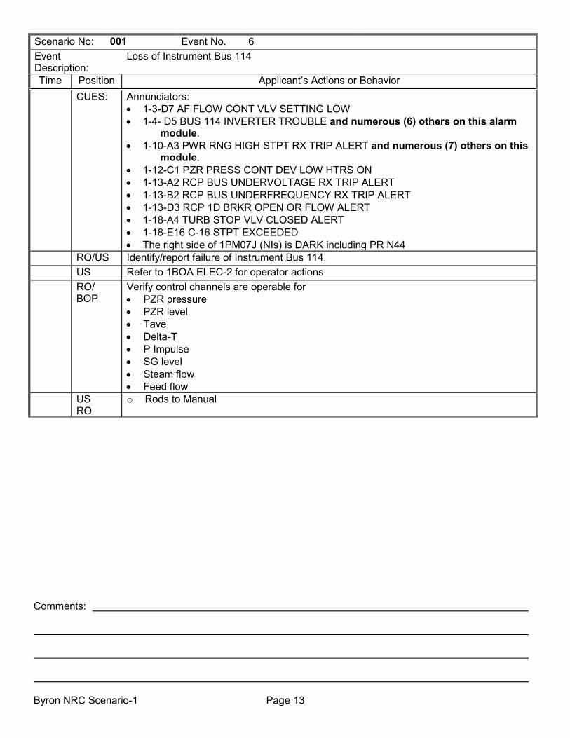
Scenario No: 001 Event No. 6 Event Description:
Loss of Instrument Bus 114
Time Position Applicant’s Actions or Behavior CUES: Annunciators:
• 1-3-D7 AF FLOW CONT VLV SETTING LOW • 1-4- D5 BUS 114 INVERTER TROUBLE and numerous (6) others on this alarm
module. • 1-10-A3 PWR RNG HIGH STPT RX TRIP ALERT and numerous (7) others on this
module. • 1-12-C1 PZR PRESS CONT DEV LOW HTRS ON • 1-13-A2 RCP BUS UNDERVOLTAGE RX TRIP ALERT • 1-13-B2 RCP BUS UNDERFREQUENCY RX TRIP ALERT • 1-13-D3 RCP 1D BRKR OPEN OR FLOW ALERT • 1-18-A4 TURB STOP VLV CLOSED ALERT • 1-18-E16 C-16 STPT EXCEEDED • The right side of 1PM07J (NIs) is DARK including PR N44
RO/US Identify/report failure of Instrument Bus 114. US Refer to 1BOA ELEC-2 for operator actions RO/
BOP Verify control channels are operable for • PZR pressure • PZR level • Tave • Delta-T • P Impulse • SG level • Steam flow • Feed flow
US RO
o Rods to Manual

Comments: Byron NRC Scenario-1 Page 14
Scenario No: 001 Event No. 6 Event Description:
Loss of Instrument Bus 114
Time Position Applicant’s Actions or Behavior RO/US • Prepare to energize Bus 114 from the CVT: (Directing EO actions in the field)
• Verify OPEN • Inverter 114 Output breaker • Bus 114 Main feed breaker
• Verify CLOSED Instr. Bus 114 CVT Feed bkr • Close Inst. Bus 114 CVT Input bkr • NOTE: EO will report BUS DAMAGE • Contact EMD to investigate damage to bus 114. • Notify Shift Manager • Perform actions associated with 1BOA INST-1 – see next step. • Refer to Tech Specs 3.8.9 Condition B for action
• Condition B: Restore I.B. in 2 hours (if not restored go to Cond. D) • Condition D: If Condition B not met, be in Mode 3 in 6 hours and Mode 5 in 36 hrs.
• Direct local Inverter 114 shutdown. ο Review Table D impacts for loss of Inst Bus 114 (Below is a portion of the list that
will be impacted at this time.) o Train B ESF loads will require manual actuation and no reset. o Rods will not withdraw in Manual o PORV 1RY455A will not open in Auto o VCT Auto makeup will not occur. o 1AF005E-H will close as soon as flow starts and cannot be controlled from the MCR. o 1SD054A-D, SD Blowdown failed closed o RCPs 1D and 1B Seal Leakoff Flow Recorders are inoperable o 1PR-403, RC WR Pressure recorder is inoperable o PR N44 is lost o SR audio counts are lost o Several TSLBs lit and 1PM05J CRTs are lost
NOTE: Actions in 1BOA INST-1 are contained on the next page (IF evaluator deems this action is necessary). These can be deferred to a request for additional NSOs to assist. With the bus damaged, this is directed action as part of this BOA action. If action is taken in 1BOA Inst-1, the first 6 steps are included on the next page. The steps to remove computer points from scan (step 7) and the bypassing or tripping of bistables associated with the failed channel have intentionally been omitted from this document

Comments: Byron NRC Scenario-1 Page 15
Scenario No: 001 Event No. 6 Event Description:
Loss of Instrument Bus 114
Time Position Applicant’s Actions or Behavior BOA INST-1 Actions
• Rod Bank Selector switch to Manual • Check for Rod Stop
• PWR RNG FLUX HIGH ROD STOP –LIT • Place Rod stop bypass switch for N-44 on 1PM07J in BYPASS
• Check Tave-Tref stable and within 1°F o Adjust rods/boron/turbine load as necessary
• SG levels NORMAL • Bypass/Defeat PR Channel Functions at 1PM07J
• Upper section and Lower section Current Comparator • Misc Control and Indication section
• Power mismatch bypass • Rod stop bypass
• Camparator and Rate Panel • Comparator Channel Defeat
• Check Flux Rate Trip Alarm • Reset N-44 at 1PM07J
The crew may fail air to the 1AF-005E-H and direct an EO to locally throttle these valves using the associated handwheels, if needed.
BOP Monitor plant for effects, address BARs, and take any actions directed by the US NOTE: When actions have been completed to respond to loss of Inst Bus 114 and
Lead Evaluator’s concurrence, Event 7 is entered.

Comments: Byron NRC Scenario-1 Page 16
Scenario No: 001 Event No. 7 Event Description:
1FW012C fails open
Time Position Applicant’s Actions or Behavior EVALUATOR NOTE: Depending on how far the crew has ramped the unit, will
determine if all actions listed below will occur. The automatic actions associated with FW pp NPSH low alarm will only occur if FW pump suction pressure reaches 400 psig
CUE • Annunciator 1-16-D2, FW PUMP DISC FLOW HIGH • Annunciator 1-16-E1, FW PUMP NPSH LOW • Annunciator 1-15-A/B/C/D4, SG 1_ FLOW MISMATCH FW FLOW LOW • Open light lit on 1FW012C • FW flow to all SG LOWERING • SG level LOWERING o FWRVs OPENING
BOP • Recognizes 1C FW pp recirc valve, 1FW12C, OPEN • Takes 1FW012C control switch to close
CREW o Review BARs • Monitor primary and secondary panels as BOP responds to FW malfunction
BOP o Reviews automatic actions for NPSH LOW annunciator o Standby Cond/Cond Bstr pump STARTS o 1CD157A/B, GS Cond. Bypass valves, OPEN o 1CD152, Cond. PPs Recirc Valve CLOSES o 1HD046A/B, Heater Drain PP Combined Disch. Valves OPEN
US • Notify SM for IR EVALUATOR NOTE: After the actions to close 1FW012C are complete and with lead
examiners concurrence, insert event 8.
EVALUATOR NOTE: If the crew trips the unit based on the FW transient the LOCA will be inserted at step 2 of 1BEP ES 0.1. The first 4 steps of 1BEP-0 along with the transition to ES 0.1 step 2 are included below.
CUE • Reactor Trip first out annunciator • Rod Bottom Lights • Automatic or manual reactor trip
CREW • Identify entry conditions for 1BEP-0, “REACTOR TRIP OR SAFETY INJECTION” US • Notify SM of plant status and procedure entry
• Request evaluation of Emergency Plan conditions • Enter/Implement 1BEP-0 and direct operator actions of 1BEP-0
RO Perform immediate operator actions of 1BEP-0: • Step 1: Verify reactor trip
• Rod bottom lights - ALL LIT • Reactor trip & Bypass breakers - OPEN

Comments: Byron NRC Scenario-1 Page 17
Scenario No: 001 Event No. 7 Event Description:
1FW012C fails open
Time Position Applicant’s Actions or Behavior • Neutron flux – DROPPING
BOP Perform immediate operator actions of 1BEP-0: • Step 2: Verify Turbine Trip
• All Turbine throttle valves - CLOSED • All Turbine governor valves - CLOSED
• Step 3: Verify power to 4KV busses • ESF Buses – BOTH ENERGIZED (141 & 142)
CREW • Check SI Status • SI First OUT annunciator –NOT LIT • SI ACTUATED Permissive Light – NOTLIT • SI Equipment – NOT ACTUATED • Check if SI is required
o Pzr Press > 1829 psig o Steam Line Press > 640 psig o Cont. Pressure < 3.4 psig
Crew • Transition to 1BEP ES-0.1 Reactor Trip Response, step 1 US • Notify SM of plant status and procedure entry
• Request evaluation of Emergency Plan conditions • Enter/Implement 1BEP ES-0.1 and direct operator actions • Request STA to monitor Status Trees
RO • Check RCS Average Temperature stable or trending to 557 degrees • Check Shutdown reactivity status
• Rod bottom lights-All Lit • RCPs- Any Running
EVALUATOR NOTE: If the crew tripped due to the feedwater transient, then initiate the next event (Large Break LOCA).

Comments: Byron NRC Scenario-1 Page 18
Scenario No: 001 Event No. 8 Event Description:
Large Break LOCA with failure of 1A and B RH pumps to automatically start
Time Position Applicant’s Actions or Behavior CUE • Pzr level is dropping
• Annunciator CNMT PRESS HIGH (0-33-D6) is LIT • Automatic reactor trip and/or safety injection actuation
CREW • Identify entry conditions for 1BEP-0, “REACTOR TRIP OR SAFETY INJECTION” US • Notify SM of plant status and procedure entry
• Request evaluation of Emergency Plan conditions • Enter/Implement 1BEP-0 and direct operator actions of 1BEP-0
RO Perform immediate operator actions of 1BEP-0: • Step 1: Verify reactor trip
• Rod bottom lights - ALL LIT • Reactor trip & Bypass breakers - OPEN • Neutron flux – DROPPING
BOP Perform immediate operator actions of 1BEP-0: • Step 2: Verify Turbine Trip
• All Turbine throttle valves - CLOSED • All Turbine governor valves - CLOSED
• Step 3: Verify power to 4KV busses • ESF Buses – BOTH ENERGIZED (141 & 142)
CREW • Check SI Status • SI First Out annunciator –LIT • SI ACTUATED Permissive Light –LIT • SI Equipment – ACTUATED
• Either SI pump – RUNNING • Either CV pump to cold leg isolation valve – OPEN – 1SI8801A
Note: examinee may open 1SI8801B at this time • Recognize SI Actuated • Manually actuate SI from 1PM05J AND 1PM06J
US • Step 5: Direct BOP to perform Attachment B of 1BEP-0 EVALUATOR NOTE: US and RO will continue in 1BEP-0 while BOP is performing
Attachment EVALUATOR NOTE: The crew may identify 1A/B RH pumps are not running and may start them before step 6. If evaluating either the SRO or RO move to step 6 on page 19
BOP Attachment B actions for the BOP are as follows: • Verify FW isolated at 1PM04J:
• FW pumps – TRIPPED. • Isolation monitor lights – LIT. • FW pumps discharge valves - CLOSED (or going closed) 1FW002A-C.

Comments: Byron NRC Scenario-1 Page 19
Scenario No: 001 Event No. 8 Event Description:
Large Break LOCA with failure of 1A and B RH pumps to automatically start
Time Position Applicant’s Actions or Behavior • Verify DGs running at 1PM01J:
• DGs – BOTH DG running • 1SX169A & B OPEN. • Dispatch operator locally to check operation
• Verify Generator Trip at 1PM01J: • OCB 3-4 and 4-5 open. • PMG output breaker open.
BOP • Verify Control Room ventilation aligned for emergency operations at 0PM02J: • VC Rad Monitors – LESS THAN HIGH ALARM SETPOINT. • Operating VC train equipment – RUNNING.
• Supply fan • Return fan • M/U fan • Chilled water pump • Chiller
• Operating VC train dampers – ALIGNED. • M/U fan outlet damper – NOT FULLY CLOSED. • VC train M/U filter light – LIT.
• Operating VC train Charcoal Absorber aligned for train B. • Bypass damper - CLOSED • Inlet damper - OPEN • Outlet damper - OPEN
• Control Room pressure greater than +0.125 inches water on 0PDI-VC038. • Verify Auxiliary Building ventilation aligned at 0PM02J:
• Two inaccessible filter plenums aligned. • Plenum A or B or C:
• Fan - RUNNING • Flow Control damper - OPEN • Bypass Isolation damper - CLOSED
• Plenum A or B or C: • Fan - RUNNING • Flow Control damper - OPEN • Bypass Isolation damper – CLOSED
• Check 1 AB exhaust fan running for every running supply fan • Verify 1 FHB ventilation aligned at 0PM02J:
• Fan - RUNNING • Inlet Isolation damper - OPEN

Comments: Byron NRC Scenario-1 Page 20
Scenario No: 001 Event No. 8 Event Description:
Large Break LOCA with failure of 1A and B RH pumps to automatically start
Time Position Applicant’s Actions or Behavior
• Flow Control damper - OPEN • Bypass Isolation damper – CLOSED
EVALUATOR NOTE: The remaining steps of Attachment B may be designated to be performed by WEC personnel or the Field Supervisor and extra operators.
o Trip all running HD Pumps o Shutdown FW pump as necessary using BOP FW-2 for a TDFP or BOP FW-8 for the
MDFP o Shutdown unnecessary CD/CB Pumps using BOP CD/CB-2 o Maintain UHS basin level greater than 80% o Align SX MDCT per BOP SX-T2
o Maintain SX Basin level > 80% o Align NDCT
o Verify CW intake bay level within band o Dispatch operator to locally verify NDCT basin level acceptable o Align NDCT per BOP CW-25
o Shutdown all unnecessary CW pumps per BOP CW-2 o Initiate periodic checking of spent fuel cooling
o Locally verify Spent fuel pool level is > 420 Elev o Locally verify SFP temperature stable o Notify STA of SFP cooling status
ο Notify US that Attachment B is complete and actions taken RO/
BOP [CT] E-0--J
• Step 6: Verify ECCS pumps running • Both CV pumps – RUNNING
• Manually start 1B CV pump due to loss of I.B. 114 • Both RH pumps – RUNNING
• Manually start 1A and 1B RH pumps prior to completion of step 6 of 1BEP-0. • Both SI pumps – RUNNING
• Manually start 1B SI pump due to loss of I.B. 114 BOP/
RO • Perform the following at 1PM06J:
• Step 7: Verify RCFCs running in Accident Mode: • Group 2 RCFC Accident Mode lights – 4 LIT. • STOP 1B RCFC is Fast Speed • CLOSE CNMT chiller inlet and outlet valves 1SX112B and 1SX114B • OPEN CNMT chiller bypass valve o OPEN RCFC inlet and outlet valves 1SX016B and 1SX027B • START B and D RCFCs in LO speed
• Step 8: Verify Phase A isolation: • Group 3 Cnmt Isol monitor lights – ALL LIT. NOTE: NOT MET

Comments: Byron NRC Scenario-1 Page 21
Scenario No: 001 Event No. 8 Event Description:
Large Break LOCA with failure of 1A and B RH pumps to automatically start
Time Position Applicant’s Actions or Behavior • Manually Actuate CNMT ISOL Phase A o Manually close valves
o Any valve outside of CNMT locally CLOSE while continuing with step 9 • Step 9: Verify Cnmt Vent isolation:
• Group 6 Cnmt Vent Isol monitor lights – ALL LIT. o Verify MSIV and Bypass Valves – CLOSED
BOP/ RO Crew
• Step 10: Verify AF system: • AF pumps – BOTH AF pumps RUNNING. Note: B pump is NOT • Start 1B AF pump • AF isolation valves – 1AF13A-H OPEN. • AF flow control valves – 1AF005A-H THROTTLED. (NOTE: unless manual
action is taken 1AF005E-H will be closed due to loss of IB 114) • Step 11: Verify CC pumps – BOTH RUNNING.
• Start 1B CC pump • Step 12: Verify SX pumps – BOTH RUNNING.
• Start 1B SX pump • Step 13: Check if Main Steamline Isolation –required:
o All S/G pressures > 640 psig (at 1PM04J). o CNMT pressure > 8.2 psig. o Verify MSIVs and Bypass valves closes o Announces containment is adverse
EVALUATOR’S NOTE: CS may have an actuation signal at this time. If it has not, the crew must return to this step to verify proper alignment when CNMT pressure exceeds 20 psig
BOP/ RO
• Step 14: Check if CS is required. • CNMT pressure has risen > 20 psig. • Group 6 CS monitor lights – ALL LIT. NOTE: B Train NOT LIT • Manually actuate CS and Phase B Isolation- 2 out of 2 switches at (at least) 1
out of 2 locations o Go to Attachment C
o Check 1CS001B OPEN o Open 1CS007B o Open 1CS019B by: o Place 1 CS pump test switch in TEST o Manually open 1CS019B o Place CS pump test switch in NORMAL o Open 1CS010B • Check one CS pump running

Comments: Byron NRC Scenario-1 Page 22
Scenario No: 001 Event No. 8 Event Description:
Large Break LOCA with failure of 1A and B RH pumps to automatically start
Time Position Applicant’s Actions or Behavior • CHECK At Least 1 CS pump running • Returns to step 14c, page 10 of 1BEP-0 • Group 6 phase B lights – ALL LIT. NOTE: B train NOT LIT o Manually actuate CS and Phase B Isolation- 2 out of 2 switches at 1 out of 2 locations o Manually CLOSE
o 1CC9413B o 1CC685 o 1CC9414
• Verify/Stop ALL RCPs (at 1PM05J). • CS eductor suction flow - > 15 gpm on 1FI-CS013. • CS eductor additive flow - > 5 gpm on 1FI-CS015.
BOP • Align SX Towers • 8 Riser valves OPEN
• OPENS 0SX163C and D • All 4 Bypass valves CLOSED • 8 fans running in HIGH speed
• Starts 0G Fan in Hi-speed BOP/
RO • Step 15: Verify Total AF flow:
• AF flow > 500 gpm • S/G NR levels – NOT rising in an uncontrolled manner and between 31 and 50%
RO/ BOP
• Step 16: Verify ECCS valve alignment • Determine Group 2 Cold Leg Injection monitor lights required for injection – NOT
All lit o Manually aligns valves as necessary
RO/
BOP • Step 17: Verify ECCS flow
• High Head SI flow >100 gpm (1FI-917) • RCS pressure < 1700 psig • SI pump Discharge flow greater than 200 gpm • RCS pressure < 325 psig • RH flow > 1000 GPM
RO • Step 18: Check PZR PORVs and SPRAY VALVES at 1PM05J: • 1RY455 & 1RY456 CLOSED • PORV isol valves – 1RY8000A & 1RY8000B BOTH ENERGIZED • PORV relief path – Both PORVs in AUTO, Both isolation valves – OPEN. (NOTE: 1RY455A will NOT operate in Auto because I.B. 114 is de-energized) • Normal PZR Spray Valves CLOSED
RO • Step 19: Maintain RCS temperature control at 1PM05J:

Comments: Byron NRC Scenario-1 Page 23
Scenario No: 001 Event No. 8 Event Description:
Large Break LOCA with failure of 1A and B RH pumps to automatically start
Time Position Applicant’s Actions or Behavior • Check RCP’s – NONE RUNNING. • Verify RCS average temperature stable at or trending to 557oF. • Throttle AF maintaining >500 GPM until SG minimum level is met • MSIVs closed
RO • Step 20: Check status of RCPs at 1PM05J: o All RCP’s – NONE RUNNING. o Any RCPs still running – TRIP All RCPs
BOP/ RO
• Step 21: Check if SG secondary pressure boundaries are intact at 1PM04J: • Check pressure in all SGs:
• None dropping in an uncontrolled manner. • None completely depressurized.
BOP/ RO
• Step 22: Check S/G tubes are intact at RM-11 console: • 1PR08J SG Blowdown. • 1PR27J SJAE/GS. • 1AR22/23A-D Main steam Lines.
CREW • Step 23: Determine RCS is NOT intact: o CNMT area rad monitors > alert alarm setpoint at RM-11 console. o CNMT pressure > 3.4 psig (1PI-CS 934-937) at 1PM06J. o CNMT floor drain sump level > 46 inches (1LI-PC002/003) at 1PM06J.
CREW Transition to 1BEP-1, ‘LOSS OF REACTOR OR SECONDARY COOLANT’ EVALUATORS NOTE: The crew will transition to 1BEP ES-1.3 when RWST Lo-2
level (<46%) is reached. May occur before step 13. 1BEP ES-1.3 actions are listed in italics below.
US • Notify SM of plant status and procedure entry • Request evaluation of Emergency Plan conditions • Enter/Implement 1BEP-1 and direct operator actions of 1BEP–1
RO • Step 1: Check Status of RCPs: • RCPs – NONE RUNNING
RO/ BOP
• Step 2: Check if SG secondary pressure boundaries are intact: • Check pressure in all SGs:
• None dropping in an uncontrolled manner • None completely depressurized
• Step 3: Check intact SG levels • SG levels maintained between 10% (31%) and 50% • SG NR levels – NOT rising in an uncontrolled manner
• Step 4: Check secondary radiation normal. • Reset Phase A
• Depress BOTH Phase A Reset Pushbuttons at 1PM06J • OPEN 1SD005A-D at 1PM11J • At RM-11 or HMI Check secondary rad trends on :

Comments: Byron NRC Scenario-1 Page 24
Scenario No: 001 Event No. 8 Event Description:
Large Break LOCA with failure of 1A and B RH pumps to automatically start
Time Position Applicant’s Actions or Behavior • 1PR08J SG Blowdown • 1PR27J SJAE/GS • 1AR22/23A-D Main steam lines • Secondary activity samples (when available)
RO • Step 5: Check at least ONE PZR PORV relief path available: • PORV isol valves – BOTH ENERGIZED • PORVs closed • PORV relief path – BOTH PORVs in AUTO, 1RY8000A & B – OPEN
EVALUATORS Prompt booth to have the STA report a RED PATH exists for 1BFR P-1.
US • When informed of the red path on 1BFR-P.1 the U.S. should • Inform the SM of the transition to P.1 and request evaluation of the Emergency Plan • Direct crew actions contained below in italic
RO • Check RCS pressure greater than 325 psig • Check RH flow Greater than 1000 GPM
US • Transitions back to 1BEP-1 Step 6 • Informs SM of procedure transition and requests evaluation of Emergency Plan. • Direct crew actions beginning at step 6
CREW
• Step 6: Check if ECCS flow should be reduced • RCS subcooling – NOT acceptable
CREW • Step 7: Check if CS should be stopped • Both CS pumps –1 RUNNING • Reset CS signal • Check Spray Add Tank Lo-2 lights – NOT lit • CS termination criteria NOT met – for LOCA, operating time at least 8 hours
CREW • Step 8: Check if RH pumps should be stopped • Reset SI
• Depress BOTH SI Reset Pushbuttons at 1PM06J • Verify SI ACTUATED BP light NOT lit at 1PM05J • Verify AUTO SI BLOCKED BP light lit at 1PM05J
• RCS pressure - NOT> 325 psig & stable CREW • Step 10: Check if DGs should be stopped
o Stop DGs and place in standby CREW • Step 11: Initiate evaluation of plant status
• Check cold leg recirc capability – BOTH trains available • Check AB rad trends normal • Obtain samples o Place H2 monitors in service per BOP PS-9

Comments: Byron NRC Scenario-1 Page 25
Scenario No: 001 Event No. 8 Event Description:
Large Break LOCA with failure of 1A and B RH pumps to automatically start
Time Position Applicant’s Actions or Behavior • Evaluate equipment for long term recovery • Shutdown chiller on non-operating VC trains o Start additional plant equipment as required
CREW • Step 12: RCS pressure – NOT > 325 PSIG • RH pump flow > 1000 GPM
CREW • Step 13: Check if transfer to 1BEP ES-1.3 required o RWST level – < 46% o ECCS – aligned in injection mode o Identify need to perform 1BEP ES-1.3
US • Transition to 1BEP ES-1.3, “Cold Leg Recirculation” • Notify SM of procedure entry and request EAL evaluation
EVALUATOR NOTE: If at any time RWST level lowers to 9% any pump taking suction on the RWST must be taken to PTL
CREW • Check/Open 1CC9473A & B • Check 2 CC Pumps – running • Open 1CC9412A & B • Check CC to RH HX flows - >5000GPM • Check CNMT floor water level – at least 13 inches
CREW [CT] ES-1.3 -- A
• Place control switches for SVAG Valve 480V busses – CLOSE • Check both RH pumps – running • Check both 1SI8811A & B – OPEN (1SI8811B is NOT) • Goes to Step 4 of Attachment A • 1SI8811B NOT fully open
o Check B RH pp running o Check 1SI8811B Energized
• Place 1B RH pump in PTL • Close 1SI8812B o Place 1B CS pp in PTL o Close 1CS001B • Open 1SI8811B • Start 1B RH pump o Reopen 1CS001B- This valve is O.O.S. o Restart 1B CS pp- The pump is O.O.S.
• Check 1 Train of Cnmt Sump recirc established • Return to main body step 4 page 8
• Check SI pump- any running • Check 1SI8801A or B open: CHG pp to Cold Leg Injection valves
CREW • Align SI and CV pumps for cold leg recirc (Step 5) • Verify closed: (CV pp mini-flows) 1CV8111, 1CV8114, 1CV8110, 1CV8116 • Close SI pump mini-flow valves 1SI8813, 1SI8814, 1SI8920

Comments: Byron NRC Scenario-1 Page 26
Scenario No: 001 Event No. 8 Event Description:
Large Break LOCA with failure of 1A and B RH pumps to automatically start
Time Position Applicant’s Actions or Behavior • Close (RH HX disc. X-tie vlvs) 1RH8716A & B • Open/verify open (SI & CV pp suct. Hdr x-tie vlvs) 1SI8807A & B, 1SI8924 • Check 1A RH Pump running • Open (RH HX to CV pps) 1CV8804A • Check 1B RH Pump running • Open (RH HX to SI pps) 1SI8804B • Start CV pumps and SI pumps as necessary
EVALUATOR NOTE: The scenario can be terminated after the first 6 steps of 1BEP ES-1.3 are completed or at lead examiner’s discretion.

Facility: _Byron Nuclear Station Scenario No.: __2__ Op-Test No.: _2013301_ Examiners: _D. McNeil__________________ Operators: _____________________________
_R. Baker___________________ _____________________________ B. Palagi
Initial Conditions: __IC-18, 75% power, steady state, MOL________________________________________ ________________________________________________________________________________ Turnover: Unit 1 is at 75% power, steady state, MOL, CB D is @ 172 steps and boron concentration is 950 ppm. Online risk is green. Crew is to switch Bus 156 from SAT to UAT following ACB 1561 maintenance. 1D CD/CB pump is OOS for maintenance.____________________________________
Event No.
Malf. No. Event Type*
Event Description
Preload
ZDI 1CD05PD PTL ZLO1CB113DOPN OFF ZLO1CB113DCLS OFF ZDI1CB113D CLS ZDI1CD05PDB PTL IMF RP02A IMF RP02B IMF TC03 ZDIHSTG010 NORM
1D CD/CB pp O.O.S. 1D CD/CB pp O.O.S. 1D CD/CB pp O.O.S. 1D CD/CB pp O.O.S. 1D CD/CB pp O.O.S. Rx trip breaker fails to open Rx trip breaker fails to open Turbine fails to AUTO trip from Rx trip Manual Turbine trip PB fails to trip turbine
1 N (BOP,SRO) Switch Bus 156 Electrical Lineup
2 None TS (SRO) Notified that 1A SI pump failed ASME surveillance
3 MF RX18A 630 I (RO, SRO) TS (SRO) 1A TCOLD RTD fail High
4 MF CV16 0 I (RO, SRO) VCT Level Channel LT-112 Fail Low
5 IMF FW22C C
(BOP,SRO) R (RO, SRO)
1C CD/CB pp Trip requiring entry to 1BOA SEC-1 and Turbine Runback
6 IMF RX04D 0 30 I (BOP,SRO) Feedwater flow channel 1FT-521 fails Low
7 MF CH08 60 120 TS (SRO) CNMT Pressure 1PT-936 Fail High
8 MF TH16C M (ALL) ATWS 1C RCP Trip with Rx Trip Breakers Fail To Open
9 Pre-load C (ALL) Failure of Main Turbine to Trip on auto signal or manual push button
*(N)ormal, (R)eactivity (I)nstrument, (C)omponent, (M)ajor Transient

Byron ILT NRC 13-2 Page 2
SCENARIO OVERVIEW
Unit 1 is at 75% power, steady state, MOL, CB D is @ 172 steps and boron concentration is 950 ppm. Online risk is green. Crew is to switch Bus 156 from SAT to UAT following ACB 1561 maintenance. 1D CD/CB is OOS for maintenance.
After completing shift turnover and relief, the crew is directed to switch Bus 156 from SAT to UAT following ACB 1561 maintenance using 1BGP 100-3, Step F.43 for reference.
During the Bus power supply swap, the Unit Supervisor will be called by Engineering stating that after reviewing the previously run ASME surveillance the 1A SI pump has failed the acceptance criteria. Entry into Tech Spec 3.5.2 Condition A will be made.
After the Unit Supvr makes the TS call, 1A Tcold RTD fails high, requiring entry to 1BOA Inst-2, Operation with a Failed Instrument Channel. This will require entry into Tech Specs by the SRO. Entry into Tech. Spec. 3.3.1 Condition A and E is made. After 1BOA Inst-2 is exited, VCT Level channel 1LT-112 fails low. RMCS auto makeup will start, and the crew will have to place the Makeup Mode Select switch to Off. Any required makeup will have to be done in Manual for the remainder of the scario.. After the level channel failure has been addressed, the 1C CB/CB pump will trip. The crew will enter 1BOA SEC-1, Secondary Pump Trip, Unit 1, attachment B. A reduction in turbine load, via runback will be required. After the run back is complete and the unit has been stabilized, the controlling feedwater flow channel on the 1B SG fails low. The BOP will take manual control of feedwater flow. 1BOA INST 2, OPERATION WITH A FAILED INSTRUMENT CHANNEL, Attachment G, will be implemented. The BOP will restore feedwater flow control to automatic when SG level is restored to normal. On line risk remains green.
After the level channel failure has been addressed, CNMT pressure channel 1PT-936 fails high. This has no immediate required actions, but the US will be responsible to evaluate Tech Specs. Crew will enter 1BOA Inst-2, Operation with a Failed Instrument Channel to address the failure. Entry into TS 3.3.2, conditions A, D & E is applicable. After the CNMT pressure channel failure has been addressed, the 1C RCP trips. When the crew attempts to trip the reactor, the trip breakers will fail to open. The manual Turbine trip P.B. will also malfunction. The turbine can be tripped via the electronic turbine trip feature associated with DEHC. The crew will enter 1BFR S.1, ATWS. At step 16, the crew will be directed to return to 1BEP-0, Reactor Trip or Safety Injection.
Completion criterion is transition to 1BEP-0, Reactor Trip or Safety Injection. The lead evaluator may end the scenario at the transition.

Byron ILT NRC 13-2 Page 3
Critical Tasks 1. Isolate the main turbine from the SGs before plant- and scenario-specific criteria are exceeded.
(ERG Critical Task number – FR-S.1--A) (K/A: EPE029EA1.13 – IR: 4.1/3.9) 2. Start AFW pumps before plant- and scenario-specific criteria are exceeded.
(ERG Critical Task number – FR-S.1 -- B) (K/A: EPE029EA1.15 – IR: 4.1/3.9)
3. Insert negative reactivity into the core by at least one of the following methods before completing the immediate-action steps of FR-S.1:
• De-energize the control rod drive MG sets • Insert RCCAs • Establish emergency boration flow to the RCS
(ERG Critical Task number – FR-S.1 -- C) (K/A: EPE029EA1.12 – IR: 4.1/4.0) SIMULATOR SETUP GUIDE:
• Verify/perform TQ-BY-201-0113, BYRON TRAINING DEPARTMENT SIMULATOR EXAMINATION SECURITY ACTIONS CHECKLIST.
• Establish the conditions of IC 18, 76% power, MOL, steady state.
• Complete items on Simulator Ready for Training Checklist.
• Verify/remove any Equipment Status Tags and Danger Tags not applicable to the scenario.
• Place simulator in RUN (allow simulator to run during board walk down and turnover).
• Verify RM-11 is on grid 1, Ensure horns are turned ON. Set BA and PW controllers to Rema numbers or 0 and reset.
• Place C/O tags on the 1D CD/CB pump C/S, its aux oil pump C/S, discharge valve C/S, and recirc valve C/S.
• Place Bus 156 on SAT.
• Ensure 1B SG FW Flow Channel is selected to F-521
• Place simulator in RUN and divert 1CV112A to get to approximately 39% VCT level.
• Open cae file: NRC 13-2.cae

Byron ILT NRC 13-2 Page 4
INSTRUCTOR/SIMULATOR RUN AID GUIDE Event 1: Switch Bus 156 Electrical Lineup Event 2: Unit Supervisor is notified that 1A SI pump has failed ASME acceptance criteria listed in 1BOSR 5.5.8.SI.5-1a SM acknowledge T/S 3.5.2 entry conditions . Event 3: 1A Tcold RTD Failed High IMF RX18A 630 As SM Acknowledge procedure entry and request for Emergency Plan evaluations. As SM Acknowledge entry into TS 3.3.1 As SM Acknowledge request for writing IR, performing risk assessment and making appropriate notifications. As SM Inform US that bistables will be tripped when personnel are available
As WEC or Extra NSO, acknowledge request to trip bistables, if Lead Examiner desires
At 1PA01J: To open protection cabinet 1, MRF RP20 OPEN To trip bistables: OPDT trip: MRF RX013 TRIP OPDT RB: MRF RX014 TRIP OTDT Trip: MRF RX135 TRIP OTDT RB: MRF RX136 TRIP Low Tave: MRF RX016 TRIP Lo-Lo Tave: MRF RX015 TRIP To close protection cabinet 1: MRF RP20 CLOSE Acknowledge as SM the 1C CD/CB pump trip, 1BOA SEC-1 entry, request for E-Plan evaluation and requests for on line risk assessment, maintenance support and IR initiation. If dispatched as EO, report that 1C CD/CB pump appears seized and the ground overcurrent flag has dropped at the breaker cubicle, Bus 159 cub 3 Acknowledge as Power Team load reduction and estimated duration of derate.

Byron ILT NRC 13-2 Page 5
Event 4: VCT Level Channel 1LT-112 Failed Low IMF CV16 0 As SM Acknowledge request for writing IR, performing risk assessment and making appropriate notifications. Event 5: Insert Malfunction FW22C to trip the C CD/CB pp Acknowledge as SM the 1C CD/CB pump trip, 1BOA SEC-1 entry, request for E-Plan evaluation and requests for on line risk assessment, maintenance support and IR initiation. If dispatched as EO, report that 1C CD/CB pump appears seized and the ground overcurrent flag has dropped at the breaker cubicle, Bus 159 cub 3 Acknowledge as Power Team load reduction and estimated duration of derate. Event 6: Feedwater flow channel 1FT-521 fails low Insert IMF RX04D 0 30 to fail 1FT-521 low over a 30 second period. As SM acknowledge the failure, on line risk assessment, request for maintenance support, and IR requests. Event 7: CNMT Pressure 1PT-936 Failed High IMF CH08C 60 120
As WEC or Extra NSO, acknowledge request to trip bistables.
As SM Acknowledge procedure entry and request for Emergency Plan evaluations. As SM Acknowledge request for writing IR, performing risk assessment and making appropriate notifications. Acknowledge entry to TS 3.3.2. Event 8: ATWS – 1C RCP trip with Rx Trip Breakers Fail to Open IMF RP02A and RP02B (in preload) IMF TH16C to trip 1C RCP As SM Acknowledge procedure entry and request for Emergency Plan evaluations. After transition to 1BFR-S.1, Acknowledge request for STA and begin monitoring BSTs. As EO, acknowledge request for local trip of Reactor Trip Breakers at 1RD05E. After crew has gone past step 7 of 1BFR S.1, DMF RP02A and RP02B, and MRF RP01 and RP02 OPEN

Byron ILT NRC 13-2 Page 6
Event 9: Main Turbine Fails to trip on auto signal or manual push button IMF TC03 ZDIHSTG010 NORM

Comments: Byron ILT NRC 13-2 Page 7
Scenario No: 002 Event No. 1 Event Description:
Switch Bus 156 Electrical Lineup
Time Position Applicant’s Actions or Behavior
CUE • (From Turnover) Realign Bus 156 to UAT following maintenance on ACB 1561 US • Refer to 1BGP 100-3 Step F. 43
• Direct BOP to switch Bus 156 to the UAT per step F.43 BOP • Switch Bus 156 Electrical Lineup
• Turn on synchroscope for Bus 156 • Close 1561 • Open 1562 • Turn off syncroscope
RO • Monitor primary and secondary panels • Control Tave with control rods or dilution as needed
EVALUATOR NOTE: When electrical swap is complete, insert the next event.

Comments: Byron ILT NRC 13-2 Page 8
Scenario No: 002 Event No. 2 Event Description:
Unit Supervisor notified of 1A SI pump ASME surveillance failure
Time Position Applicant’s Actions or Behavior NOTE: At Lead Evaluators Discretion this event may be bypassed. CUE • US called by Engineering that 1A SI pump ASME surveillance acceptance criteria has
NOT been met. US • Refers to TS 3.5.2 determines that Condition A applies:
• Condition A: Restore pump to operable w/i 7 days • Calls SM and informs same of condition. Requests, evaluation for on-line risk, IR
initiation and maintenance informed. ο May request BOP/RO to place affected pump in PTL.
EVALUATOR NOTE: After the Tech. Spec. condition has been determined and with lead examiners concurrence, insert the next event.
Comments: Byron ILT NRC 13-2 Page 9
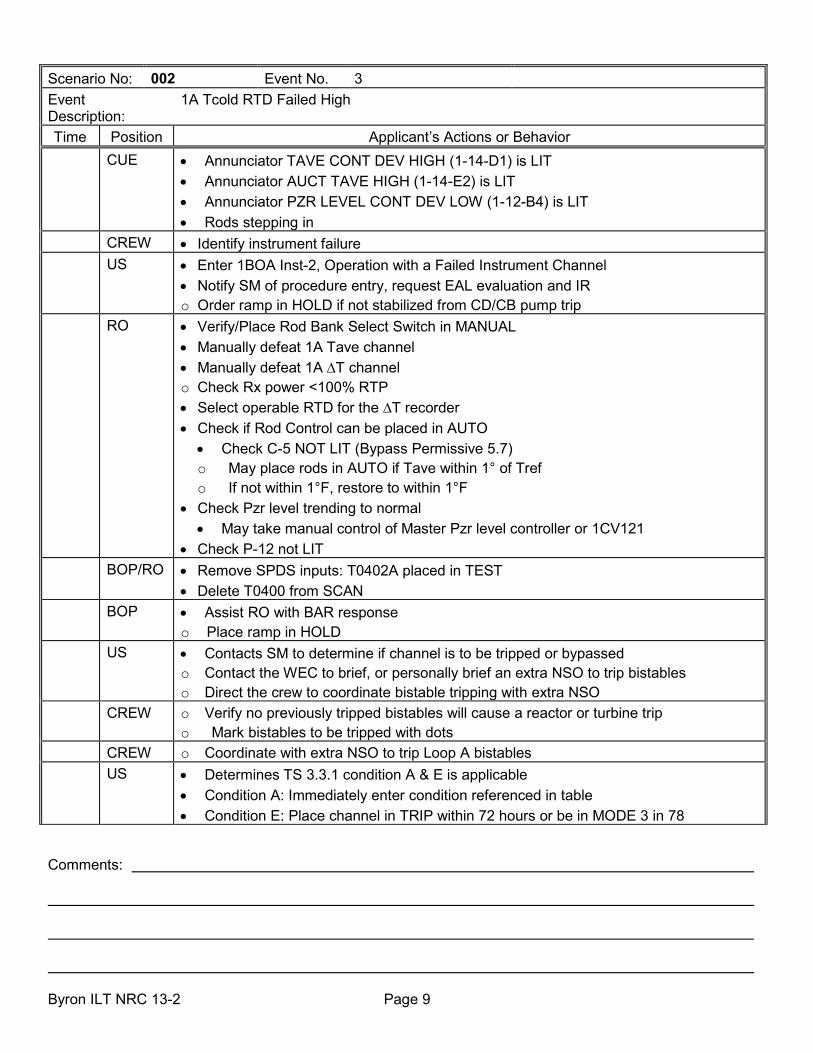
Scenario No: 002 Event No. 3 Event Description:
1A Tcold RTD Failed High
Time Position Applicant’s Actions or Behavior CUE • Annunciator TAVE CONT DEV HIGH (1-14-D1) is LIT
• Annunciator AUCT TAVE HIGH (1-14-E2) is LIT • Annunciator PZR LEVEL CONT DEV LOW (1-12-B4) is LIT • Rods stepping in
CREW • Identify instrument failure US • Enter 1BOA Inst-2, Operation with a Failed Instrument Channel
• Notify SM of procedure entry, request EAL evaluation and IR o Order ramp in HOLD if not stabilized from CD/CB pump trip
RO • Verify/Place Rod Bank Select Switch in MANUAL • Manually defeat 1A Tave channel • Manually defeat 1A ∆T channel o Check Rx power <100% RTP • Select operable RTD for the ∆T recorder • Check if Rod Control can be placed in AUTO
• Check C-5 NOT LIT (Bypass Permissive 5.7) o May place rods in AUTO if Tave within 1° of Tref o If not within 1°F, restore to within 1°F
• Check Pzr level trending to normal • May take manual control of Master Pzr level controller or 1CV121
• Check P-12 not LIT BOP/RO • Remove SPDS inputs: T0402A placed in TEST
• Delete T0400 from SCAN BOP • Assist RO with BAR response
o Place ramp in HOLD US • Contacts SM to determine if channel is to be tripped or bypassed
o Contact the WEC to brief, or personally brief an extra NSO to trip bistables o Direct the crew to coordinate bistable tripping with extra NSO
CREW o Verify no previously tripped bistables will cause a reactor or turbine trip o Mark bistables to be tripped with dots
CREW o Coordinate with extra NSO to trip Loop A bistables US • Determines TS 3.3.1 condition A & E is applicable
• Condition A: Immediately enter condition referenced in table • Condition E: Place channel in TRIP within 72 hours or be in MODE 3 in 78

Comments: Byron ILT NRC 13-2 Page 10
Scenario No: 002 Event No. 3 Event Description:
1A Tcold RTD Failed High
Time Position Applicant’s Actions or Behavior o Channel may be BYPASSED for up to 12 hours for surveillance testing o TRM 3.h: not applicable because required channels are OPERABLE (PDMS)
EVALUATOR NOTE: After the actions for the instrument failure are complete and with Lead Examiners concurrence, insert the event 4.

Comments: Byron ILT NRC 13-2 Page 11
Scenario No: 002 Event No. 4 Event Description:
VCT Level Channel 1LT-112 Failed Low
Time Position Applicant’s Actions or Behavior CUE • Annunciator VCT LEVEL HIGH-HIGH LOW is LIT
• VCT Level 1LI-112 indicates ZERO • Automatic RMCS makeup in operation
CREW • Refer to BAR 1-9-A2 • Determine 1LT-112 is failed LOW
RO • Place RMCS makeup switch in OFF • Monitor VCT level o Makeup to VCT in MANUAL if required
US • Notify SM of failure, request IR BOP • Monitor primary and secondary panels
• Assist with BAR response EVALUATOR NOTE: Only manual make-up control will be available for the
remainder of this scenario EVALUATOR NOTE: After the actions for the VCT level failure are complete and
with Lead Examiners concurrence, insert the event 5.

Comments: Byron ILT NRC 13-2 Page 12
Scenario No: 002 Event No. 5 Event Description:
1C CD/CB Pump Trip with Runback required
Time Position
Applicant’s Actions or Behavior
CUE • Annunciator CD/CB PUMP TRIP (1-17-A9) is LIT US • Enter and direct actions of 1BOA Sec-1, Secondary Pump Trip
• Notify SM of procedure entry and request EAL evaluation BOP • Check turbine load: > 700 MW
• Check a Standby CD/CB pump cannot be started • Determines 3 CD/CB pps NOT running • Initiates a CD/FW runback by push button or panel G5512 • Check Turbine Load DROPPING
RO o Monitor RCS Tave and reactivity effects caused by secondary feedflow changes. • Places Rods in AUTO • Initiates boration as necessary • Set up boration IAW ReMa and BOP CV-6 • Initiate boration using BOP CV-6 or BOP CV-6T1 checklist
• Select STOP on RMCS Makeup Control Switch • Select BORATE on RMCS Mode Select Switch • Enter desired boration amount in BA totalizer (NOTE to Evaluator: 295 gals of BA
needed to reduce power from 1200 MW to 700 MW. RO should deliver about 100 gals of BA to reduce load by approximately 150 MW from current conditions)
• Turn ON RMCS Makeup Control Switch • Verify 1CV110B OPEN • Verify 1CV110A MODULATING • Verify 1AB03P STARTS • Verify proper AB flow on 1FR110
• Coordinate boration with unit ramp by BOP • Maintain Tave-Tref within 3°F o Assist BOP with BAR response
BOP • Check FW pumps not cavitating • Close 1CB113C o Check FW pump discharge flow: NOT oscillating o Reduce FW pp flow while maintaining >50% level in SGs • Continue to monitor FW pp performance • Check Alarms NOT LIT
o CB PP DSCH Flow High (1-17-B11)

Comments: Byron ILT NRC 13-2 Page 13
Scenario No: 002 Event No. 5 Event Description:
1C CD/CB Pump Trip with Runback required
Time Position
Applicant’s Actions or Behavior
o FWpp NPSH LOW (1-16-E1) RO/BOP • Check Plant Status
o PDMS INOPERABLE alarm (1-10-D8) IS lit o 1BOL 3.h IS implemented o Control DI near target o Rod bank RIL alarm (1-10-B6) NOT lit o Turbine RB Light (OWS graphic 5501) is NOT lit o C-7 (BP 4.6) NOT lit
US o IF RCS pressure lowers to less than 2209 PSIG, evaluate DNB TS 3.4.1 CREW • Restore Plant Conditions
• Adjust RCS boron concentration as necessary • Verify controls for running equipment in - AUTO:
o TDFP o HD pump discharge o CB pump recircs o CD pumps recirc o GS condenser bypasses
• Complete shutdown of tripped CD/CB pump per BOP CD/CB-2, CONDENSATE/CONDENSATE BOOSTER SYSTEM SHUTDOWN
• Adjust SG blowdown flows and calorimetric inputs as necessary • Verify DEHC feedback loop in service • Notify Chemistry to monitor secondary chemistry o Complete applicable section(s) of 1BGP 100-4 (if runback performed) • Check Reactor power change > 15% in one hour. If so:
o Notify Chemistry and RP to perform the power change surveillances • Notify Shift Manager to perform step 8 of 1BOA SEC-1 Attachment B for CD/CB Trip EVALUATOR NOTE: After the unit has stabilized and with Lead Examiners
concurrence, insert event 6.

Comments: Byron ILT NRC 13-2 Page 14
Scenario No: 002 Event No. 6 Event Description:
Feedwater flow channel 1FT-521 fails low
Time Position
Applicant’s Actions or Behavior
CUE • Annunciator 1B SG FW FLOW MISMATCH (1-15-B4) • FW flow indicator 1FI-521A lowering • FW flow indicator 1FI-520A rising • FWRV 1FW-520 opening • SG level indicators 1LI-527, 528, 529, 557 rising
BOP • Identify 1FT-521 failed low • Report failure to US • Perform the following at 1PM04J
• Place 1FW-520 in MANUAL • Lower FW flow to match or slightly lower than steam flow • Monitor 1B SG level and control 1FW-520 in MANUAL
RO • Assist BOP as requested • Monitor reactor panel for reactivity changes
CREW o Refer to BARs • Identify entry conditions for 1BOA INST 2, OPERATION WITH A FAILED
INSTRUMENT CHANNEL, Attachment G.
US • Notify SM of plant status and procedure entry. • Request evaluation of Emergency Plan conditions. • Enter/Implement "1BOA INST-2, “OPERATION WITH A FAILED INSTRUMENT
CHANNEL", Attachment G.
BOP • Select operable SG level channel F-520 on 1FS-520C • Check 1B SG level – normal on 1LI-527, 528, 529, 557 • Place 1FW-520 in AUTOMATIC
Crew • Check reactor power <100% BOP • HD pp disc. flow control valve position – Normal Crew o Evaluate impact on calorimetric EVALUATOR NOTE: After the actions for the feedwater flow channel failure are
complete and with Lead Examiners concurrence, insert the event 7.

Comments: Byron ILT NRC 13-2 Page 15
Scenario No: 002 Event No. 7 Event Description:
CNMT Pressure 1PT-936 Failed High
Time Position Applicant’s Actions or Behavior CUE • Annunciator CNMT PRESS HI-3 (1-3-D4) is LIT
• Annunciator CNMT PRESS HI-2 (1-3-C4) is LIT • Annunciator CNMT PRESS HIGH (1-3-B4) is LIT • Indicator 1PI-CS936 indicates 60 PSIG
US • Enter 1BOA Inst-2, Operation with a Failed Instrument Channel, Att K • Notify SM of procedure entry, request E-Plan evaluation and IR • Contacts SM to determine if channel is to be tripped or bypassed o Contact the WEC to brief, or personally brief an extra NSO to trip bistables o Direct the crew to coordinate bistable tripping with extra NSO
US • Notify WEC to, or perform brief of extra NSO to trip bistables • Direct crew to coordinate tripping bistables with extra NSO
CREW o Verify no previously tripped bistables will cause a reactor or turbine trip o Mark bistables to be tripped with dots
US • Enter TS 3.3.2, conditions A, D & E • Condition A: Immediately enter condition referenced in table • Condition D: (Cont Press Hi-1) Place channel in TRIP within 72 hours or be in MODE
3 in 78 and MODE 4 in 84 • Condition E: (Cont Press Hi-3) Place channel in BYPASS within 72 hours or be in
MODE 3 in 78 and MODE 4 in 84 • One additional channel may be BYPASSED for up to 12 hours for surveillance testing
EVALUATOR NOTE: After the actions for the failed pressure channel are complete and with Lead Examiners concurrence, insert event 8.

Comments: Byron ILT NRC 13-2 Page 16
Scenario No: 002 Event No. 8 Event Description: 1C RCP Trip with ATWS Time Position Applicant’s Actions or Behavior
CUE • The following annunciators are LIT: • RCP TRIP (1-13-E3) • RCP 1C BRKR OPEN OR FLOW LOW ALERT (1-13-C3)
CREW • Identify entry conditions for 1BEP-0, “REACTOR TRIP OR SAFETY INJECTION” EVALUATOR NOTE: The crew may dispatch an operator to open the reactor trip
breakers before reaching step 6. US • Enters 1BEP-0, “REACTOR TRIP OR SAFETY INJECTION”
• Transition to 1BFR S.1, “ATWS” • Notify SM of procedure entry • Request EAL evaluation and STA to monitor BSTs
RO o Rod Bottom lights -NOT LIT o Rx Trip and Bypass Bkrs- NOT ALL OPEN • Manually TRIP the Reactor from BOTH locations • Allow rods to insert automatically until rod speed less than 48 SPM, then manually
insert rods CREW
[CT] FR-S.1--A
• Manually trip the Turbine o All Turbine throttle valves – CLOSED. o All Turbine governor valves – CLOSED. • Recognizes the Turbine did not auto trip from Reactor trip • Manually trip the turbine
o Actuate manual trip P.B. o Operate the manual trip soft key on the OWS G-5512 panel • Select turbine manual on G-5501 panel • Select RAPID • Select and hold GV lower arrow OR o Manually actuate Mainsteam Line Isolation
CREW [CT] FR-S.1--B
• Manually start both AF pumps I NEED a TIME
RO/BOP [CT] FR-S.1--C
• Verify/ensure Control Rods inserting in Manual or Auto at least 48 steps per minute
• Check at least 1 CV pump running • Initiate emergency boration by
• Open 1CV8104 • Start boric acid transfer pump

Comments: Byron ILT NRC 13-2 Page 17
Scenario No: 002 Event No. 8 Event Description: 1C RCP Trip with ATWS Time Position Applicant’s Actions or Behavior
• Check emergency boration and charging flows > 30 GPM RO/BOP
• Check Pzr pressure < 2335 PSIG • Verify Group 6 CVI monitor lights LIT
CREW • Check if Reactor Trip has occurred • Dispatch EO to locally open Rx Trip Breakers
• Check Turbine Trip occurred EVALUATOR NOTE: Depending on timeframe, the crew may go to either step 8
or step 16 at this point. Steps 8-15 are in italics. CREW • Check if Reactor is subcritical
• PR channels <5% • IR channels – negative SUR
CREW • Check SG NR levels > 1 SG >10% • Control feed flow to maintain SG NR level 10% - 50% • Check 1SD002A-H closed • Check 1CV111A & B closed • Verify BTRS MODE SELECTOR SWITCH is OFF • Dispatch operator to verify dilution paths are isolated o Check for RCS temperature NOT dropping uncontrollably o Check for any SG pressure NOT dropping uncontrollably
• EVALUATOR NOTE: If RCS is cooling down or SG are depressurizing, the crew will perform steps 11-13
CREW o Step 11: Check/close MSIVs and bypass valves closed o Step 12: Check SG pressure NOT dropping uncontrollably or depressurized o Step 13: Isolate Faulted SG
CREW • Step 14: Check CETC < 1200°F • Step 15: Verify reactor subcritical
• PR channels < 5% • IR channels – negative SUR
Crew • Return to procedure and step in effect US • Announces transition to 1BEP-0, Reactor Trip or Safety Injection EVALUATOR NOTE: The scenario can be terminated after the transition to
1BEP-0 is announced or at Lead Examiner’s discretion.

Facility: _Byron Nuclear Station Scenario No.: __3__ Op-Test No.: _2013301_ Examiners: _D. McNeil__________________ Operators: ____________________________
_R. Baker___________________ ____________________________ _D. McNeil__________________ ____________________________
Initial Conditions: __IC-16, 56% power, steady state, equilibrium xenon, BOL____________________ _________________________________________________________________________________ Turnover: Unit 1 is at 56% power, steady state, equilibrium xenon, BOL CB D is at XXX steps and boron concentration is 998 ppm. Preconditioned to 100% power at 6400 EFPH. Online risk is yellow. 1A CS pp is O.O.S. for a motor lube oil change and is scheduled to be released at the end of shift. It is expected that Power Team will call for the unit to be ramped to 880 MWe at .2MW/min._____________
Event No. Malf. No. Event
Type* Event
Description
Preload
IOR ZDI1CS01PA PTL IMF CS01A IRF CS05 OVER IMF CH01B IMF CH01C
Preload
1A CS pp O.O.S. 1A CS pp fails to start Prevents 1B CS pp from Auto start 1B RCFC fails to start in Lo Speed 1C RCFC fails to start in Lo Speed
1 None (from 10-1-5 cert)
N (BOP, SRO)
R (RO, SRO)
Ramp unit up
2 IMF RD13AK08 TS (SRO) DRPI failure (1 rod) in CB A for 1 train
3 IMF CV07A 80 60 C (RO, SRO) RCP Seal Injection Filter Clogged
4 IMF RX13A 100 I (RO,
SRO) TS (SRO)
Pzr LT-459A Fail High (controlling channel)
5 IMF FW02A C (BOP, SRO) 1B TDFP Trip
6 IMF RX01K 0-(from 10-1-1 cert)
I (BOP, SRO)
TS (SRO)
Steam Generator 1D controlling Steam Pressure channel fails low requiring Manual control of 1D SG Main Feed Reg Valve. Enter Tech Spec 3.3.2 for actions.
7 IMF MS07D 4 240 M (ALL) 1D Steam Line Break inside CNMT
8
(Preloaded) MF CS01A RF CS05 OVER IMF CH01B IMF CH01C
C (SRO, CREW)
CS Pumps Auto Start Failure, Manual Start required; 1B CS pump fail to auto start due to 1CS019B failure to auto open 1B RCFC fails to start in Lo Speed 1C RCFC fails to start in Lo Speed
*(N)ormal, (R)eactivity (I)nstrument, (C)omponent, (M)ajor Transient

Byron ILT NRC 10-1 Page 2
SCENARIO OVERVIEW
Unit 1 is at 56% power, steady state, equilibrium xenon, MOL CB D is at 149 steps and boron concentration is 999 ppm. Online risk is yellow. The crew is to ramp the unit to 880 MWe at 0.2 MW/min
After completing shift turnover and relief, the crew will commence the ramp up by dilution to 880 MWe.
Before the ramp has commenced, a DRPI failure will occur on Rod K-8 requiring the U.S. to consult Tech Spec. 3.1.7
After the ramp has commenced, the annunciator for RCP Seal Injection High DP will alarm. BOP CV-10, CV Filter Operations will be utilized to swap Seal Injection Filters. The crew may enter 1BOA RCP-2, Loss of Seal Cooling, which directs the use of BOP CV-10 to swap filters. Since the standby filter is placed in service, 1BOSR 5.5.1-1 is required to be performed IAW Tech Spec 3.5.5. This evolution is NOT included with this material.
After normal seal injection flow is restored and the plant stabilized, Pressurizer level transmitter 1LT-459A, the controlling channel, fails high. The RO will take manual control of either the Master Pzr level controller or 1CV121 to raise charging. The crew will enter 1BOA Inst-2, and there is a high level bistable to be eventually tripped. The SRO will refer to Tech. Specs 3.3.1, 3.3.4 and 3.3.3. TS 3.3.1, conditions A and K are applicable.
After the actions for the Pzr control malfunction are completed, 1B TDFP spuriously trips, causing a reduction in feedwater flow. The crew will enter 1BOA Sec-1. After taking actions for the Feedwater pump trip and the plant stabilizes, the 1D SG controlling steam pressure channel, 1PT 545A, will fail low requiring manual control of the 1D SG feedwater regulating valve. The SRO will enter 1BOA INST-2, for the failed SG Steam pressure channel and direct actions to restore the 1D feedwater regulating valve to automatic control. Tech Spec 3.3.2, Conditions A and D apply.
After the ramp has been initiated, a 4 Mlb/hour fault develops and ramps in over 240 seconds in the 1B Steam Line inside Containment. The crew will trip or verify a trip of the reactor, initiate or verify Main Steam Line isolation, and initiate or verify Safety Injection. The crew will enter 1BEP-0, Reactor Trip or Safety Injection, transition to 1BEP-2, Faulted Steam Generator Isolation, then transition to 1BEP ES-1.1, SI Termination.
The Containment Spray pumps will not automatically start, requiring the crew to manually actuate Containment Spray. Only the 1B CS pump will start. In addition, 2 RCFC will not start in low speed which will require a CS pump to function.
Completion criterion is transition to 1BEP ES-1.1, SI Termination. The lead evaluator may end the scenario at the transition, or after SI has been terminated.
Critical Tasks
1. Manually actuate at least the minimum required complement of containment cooling equipment before an
extreme (red-path) challenge develops to the containment CSF. (ERG Critical Task number – E-0--E) (K/A: 026000A4.01 – IR: 4.5/4.3) 2. Isolate the faulted SG before transition out of E-2.
(ERG Critical Task number – E-2--A) (K/A: APE040AA1.10 – IR: 4.1/4.1)

Byron ILT NRC 10-1 Page 3
SIMULATOR SETUP GUIDE:
• Verify/perform TQ-BY-201-0113, BYRON TRAINING DEPARTMENT SIMULATOR EXAMINATION SECURITY ACTIONS CHECKLIST.
• Establish the conditions of IC 16, 56% power, MOL, steady state, equilibrium xenon.
• Complete items on Simulator Ready for Training Checklist.
• Verify/remove any Equipment Status Tags and Danger Tags not applicable to the scenario.
• Place C/O tags on 1A CS pp MCB C/S
• 1A Seal Injection filter on line placard placed on 1PM05J
• Place simulator in RUN (allow simulator to run during board walk down and turnover).
• Verify RM-11 is on grid 1, Ensure horns are turned ON. Set BA and PW controllers to Rema numbers or 0 and reset.
• Ensure 1D SG STEAM FLOW channel selected to F-543
• Open Cae file: NRC 13-3.cae

Byron ILT NRC 10-1 Page 4
INSTRUCTOR/SIMULATOR RUN AID GUIDE Event 1: Ramp Unit 1 to 880 MWe at 0.2 MWe/min. Event 2: 1 Rod DRPI Failure IMF RD13AK08 As SM Acknowledge Tech Spec entry. As SM Acknowledge request for writing IR, performing risk assessment and making appropriate notifications. Event 3: RCP Seal Injection Filter clogged IMF CV07A 80 60 AS EO, report 1A Seal Injection filter DP at 35 PSID (High alarm setting is 29 PSID). When directed, swap to the 1B filter IAW BOP CV-10. Open 1CV8384B by MRF CV42 100 and close 1CV8384A by MRF CV41 0. A few minutes after filters are swapped call as the A.B. E.O. and inform U.S. of step in procedure to perform 1BOSR 5.5.1-1 As SM Acknowledge procedure entry and request for Emergency Plan evaluations. As SM Acknowledge request for writing IR, performing risk assessment and making appropriate notifications. Event 4: Respond to Pressurizer Level Channel Failure IMF RX13A 100 As SM Acknowledge procedure entry and request for Emergency Plan evaluations. As SM Acknowledge entry into Tech Spec LCOAR As SM Acknowledge request for writing IR, performing risk assessment and making appropriate notifications. As SM inform US that bistables will be tripped when personnel are available As WEC or Extra NSO, acknowledge request to trip bistables. To trip bistables, MRF RP20 OPEN to open Protection Cabinet 1, MRF RX029 TRIP for LB459A

Byron ILT NRC 10-1 Page 5
Event 5: 1B TDFP Trip IMF FW02A As EO, if asked to investigate the cause of the pump trip, report no visible cause, but there is scaffold material piled on the floor by the local control panel, and that you (the EO) will talk to the carpenters. As SM Acknowledge procedure entry and request for Emergency Plan evaluations. As SM Acknowledge request for writing IR, performing risk assessment and making appropriate notifications. Event 6: Steam Generator 1D controlling Steam Pressure channel fails low (1PT545A). Initiate event after event 5 actions completed Acknowledge all info passed to the SM, WEC, and maintenance. SDG: RX16 IMF RX01K 100 If requested to trip bistables, and Lead Examiner wants to see this action: MRF RP21 OPEN/CLOSE MRF RX 095 Trip MRF RX 096 Trip Otherwise, there are NO NSO’s available to trip bistables for 2 hours As SM Acknowledge procedure entry and request for Emergency Plan evaluation As SM Acknowledge request for writing IR, performing risk assessment and making appropriate notifications. Event 7: 1D Steam Line Break inside Containment IMF MS07D 4 240 to cause a 4 MLB/hr steam line break on the 1D Steam Line inside CNMT. As SM Acknowledge procedure entry and request for Emergency Plan evaluations. After transition to 1BEP-2, Acknowledge request for STA and begin monitoring BSTs. Event 8: CS Pump Failure to automatically start

Comments: Byron ILT NRC 10-1 Page 6
Scenario No: 003 Event No. 1 Event Description:
Raise power at 0.66 MW/min
Time Position
Applicant’s Actions or Behavior
CUE o Direction from Power Team to raise power to 880 MW at 0.4 Mw/min.
US
• Acknowledge request to raise power to 880 MW at 0.2 Mw/min. • Implement actions of 1BGP 100-3. o Perform pre-job brief per HU-AA-1211 “PRE-JOB, HEIGHTENED LEVEL OF
AWARENESS, INFREQUENT PLANT ACTIVITY, AND POST JOB BRIEFINGS” for load ramp.
US • Direct raising load to 880MW at 0.66 MW/min. • Initiate load swing instruction sheet, 1BGP 100-3T5.
CREW • Review applicable Precautions, and Limitations and Actions. NOTE: The ramp strategy will be about 130 gallons of PW about every 15 minutes and
supplement with rods to control temperature. This will result in about a 3% per hour change in Rx power.
RO • Verify rod position and boron concentration. o Perform dilution boundary calculation per 1BGP 100-3T5.
• Determine required PW volume: (approximate band: 1200 gal – 1400 gal). ο Rema
• Determine required PW flow rate. • Initiate dilution as required (BOP CV-5). • Perform the following at 1PM05J:
• Set 1FK-111 PW/Total Flow Cont POT to the desired PW flow rate. • Set 1FY-0111 PW Control Predet Counter to desired PW volume. • Place MAKE-UP CONT SWITCH to STOP position. • Set MODE SELECT to DIL/ALT DIL position. • Place MAKE-UP CONT Switch to START. ο Verify proper operation of valves and PW makeup pump (1CV111B open, 1CV111A
throttled, 1CV110B open (ALT DIL only), PW pump running, PW flow on recorder). ο Turn on PZR backup heaters.
BOP • Raise turbine load at 1PM02J or OWS drop 210 by performing the following:
• Select SETPOINT. • Enter 0.66 MW/min into the RATE window. • Select ENTER. • Enter 880 MW into REF DEMAND window. • Select ENTER. • Select EXIT.

Comments: Byron ILT NRC 10-1 Page 7
Scenario No: 003 Event No. 1 Event Description:
Raise power at 0.66 MW/min
Time Position
Applicant’s Actions or Behavior
o Notify US and RO of pending ramp. • Select GO/HOLD. • Verify GO/HOLD button illuminates. • Verify HOLD illuminated RED. • Select GO. • Verify GO illuminates RED. • Verify main turbine load begins to rise.
RO/
BOP • Monitor reactor power and load ascension:
• Monitor NI’s, Tave, ∆I, Pzr press/level at 1PM05J. • Monitor MW and DEHC system response at 1PM02J or OWS drop 210.
• During dilution, monitor the following at 1PM05J and HMI: • VCT level. • RCS Tave rising/RCS boron concentration lowering. • PW/Total flow predet counter responding correctly. • Verify dilution auto stops at preset value. • Return Reactor Makeup System to automatic.
After measurable change in power and Lead Examiner approval, initiate the event 2.

Comments: Byron ILT NRC 10-1 Page 8
Scenario No: 003 Event No. 2 Event Description:
DRPI Failure 1 rod in 1 train on CB A
Time Position Applicant’s Actions or Behavior CUE • Annunciator 1-10-D6 Rod Cont Non-Urgent Failure
• SER 2150 in alarm • Data B failure on Rod K-8
Crew
• Acknowledge annunciator. • Open BAR • Check SER alarm
RO o Place Bank Select Switch in Manual US • Notify SM and requests IR generation
• Requests an extra NSO perform BOP RD-8, DRPI System Troubleshooting • Review Tech Specs
• 3.1.7 Condition A applies: Verify the position of the rods with inoperable DRPIs once per 8 hours or reduce power to < 50% • TRM 3.1.g- Determines the TRM is not applicable

Comments: Byron ILT NRC 10-1 Page 9
Scenario No:
003 Event No.
3
Event Description:
RCP Seal Injection Filter Clogged
Time Position
Applicant’s Actions or Behavior
CUE • Annunciator RCP Seal Inj Filter High DP (1-7-A2) LIT • Annunciator RCP Seal Water Inj. Flow Low (1-7-B2) LIT • Seal injection flows lowering
RO • Adjust 1CV182 to maintain at least 8 GPM seal injection flow per RCP o Adjust 1CV121, if necessary
CREW o Dispatch EO to check 1A Seal Injection filter DP • Dispatch EO to swap seal injection filters using BOP CV-10, CV Filter Operations
Evaluator Note: The crew may enter 1BOA RCP-2 for the loss of seal cooling. This will direct swapping filters using BOP CV-10. Actions of 1BOA RCP-2 follow in italics.
US • Implement 1BOA RCP-2, Loss of Seal Cooling • Notify SM of procedure entry, requests IR and EAL evaluation
RO o Verify RCP seal cooling is met with RCP temperatures within limits • Restore Seal Injection
• Dispatch EO to swap seal injection filters using BOP CV-10, CV Filter Operations • Control seal injection flow with 1CV182 and 1CV121 to 8 – 13 GPM per RCP
BOP • Assist in monitoring primary plant while RO controls seal injection flow. • Provide assistance in diagnosis and BAR response.
US • Direct initiation of or initiate 1BOSR 5.5.1-1, RCS Seal Water Injection Flow Monthly Surveillance after standby filter is placed on line.
EVALUATOR NOTE: After the actions for the seal filter malfunction are complete and with Lead Examiners concurrence, insert event 4.

Comments: Byron ILT NRC 10-1 Page 10
Scenario No: 003 Event No. 4 Event Description:
Pressurizer level channel 1LT-459 failed high
Time Position Applicant’s Actions or Behavior CUE • Annunciator PZR LEVEL HIGH RX TRIP STPT ALERT (1-12-A3) is LIT
• Annunciator PZR LEVEL HIGH CONT DEV HTRS ON (1-12-C3) is LIT • 1LI-459A indicates 100% level • Charging flow lowering
CREW o Refer to BARs. • Identify entry conditions for 1BOA INST-2, “OPERATION WITH A FAILED
INSTRUMENT CHANNEL”. US • Notify SM of plant status and procedure entry.
• Request evaluation of Emergency Plan conditions. • Implement 1BOA INST-2 "OPERATION WITH A FAILED INSTRUMENT CHANNEL",
Attachment C "PRESSURIZER LEVEL CHANNEL FAILURE" and direct operator actions of 1BOA INST-2
RO • Perform the following at 1PM05J: • Place 1FK-121, CV pumps flow control valve, and/or 1LK-459, PZR master level
controller, in manual. • Raise demand on 1FK-121 and/or 1LK-459 in conjunction with controlling demand
on 1CV182 to raise charging flow. • Operate 1FK-121 and/or 1LK-459 in manual to minimize PZR level drop and maintain
8-13 gpm RCP seal injection flow. • Select an operable Pzr level channel for control- 461/460 • Select an operable Pzr level channel to the recorder • Place 1FK-121, CV pumps flow control valve, and/or 1LK-459, PZR master level
controller, as appropriate, in automatic. US • Contact SM or WEC for tripping bistables
o Verifies tripping bistables will NOT result in a Rx TRIP
o Perform pre-job brief per HU-AA-1211 for bistable tripping. o Complete 1BOL 3.1, Attachment B, “INSTRUMENT CONDITION TRACKING LOG”.
Extra NSO/ RO
o Locally trip bistable for 1LT-459 / RO verifies correct bistable operation
US • Determine TS 3.3.1 conditions A and K are applicable.
• Condition A- Immediately enter the table
• Condition K- Place channel in TRIP in 72 hours or reduce power to < P-7 in 78 hours • Determine TS 3.3.3 and 3.3.4 are NOT applicable – minimum channels operable
requirement is met. o May decide to make a Degraded Equipment Log Entry

Comments: Byron ILT NRC 10-1 Page 11
Scenario No: 003 Event No. 4 Event Description:
Pressurizer level channel 1LT-459 failed high
Time Position Applicant’s Actions or Behavior • Contact SM to perform risk assessment, initiate IR, and contact maintenance to
investigate/correct instrument failure. BOP • Monitor secondary systems
• Assist RO with annunciator response EVALUATOR NOTE: After the instrument failure has been addressed and with lead
examiners concurrence, insert event 5.

Comments: Byron ILT NRC 10-1 Page 12
Scenario No: 003 Event No. 5 Event Description:
1B TDFP trip
Time Position Applicant’s Actions or Behavior CUE • Annunciator FW Pump 1B Trip (1-16-B2) is LIT
• Annunciators SG 1A-D Flow Mismatch FW Flow Low (1-16-A:D4) are LIT • Annunciator FW Pump Discharge Flow High (1-16-D2) is LIT o Auto start of standby CD/CB pump with associated alarms LIT • SG levels lowering
US • Enter 1BOA Sec-1, Secondary Pump Trip, Attachment A for FW Pump trip o Direct BOP to close 1FW012B o Direct RO/BOP to monitor SG levels for Reactor Trip criteria • Notify SM of plant status, procedure entry, request IR and maintenance notification
and EAL evaluation BOP • Close 1FW012B
• Check Turbine load > 700 MW • Check at least 1 FW pump running • Restore feed flow • Check FW PUMP NPSH LOW alarm LIT • Verify CP bypass valves are open: 1CD210A and B.
US • Orders the power ascension stopped, if not already CREW • Restore Plant Conditions
• Adjust RCS boron concentration as necessary • Balance FW pump flows as necessary • Verify FW pump recirc valves on running FW pumps in - MODULATE • Verify valve controls for running equipment in - AUTO:
o HD pump discharge o CB pump recircs o CD pumps recirc o GS condenser bypasses
o Shutdown unnecessary CD/CB pump per BOP CD/CB-2, CONDENSATE/CONDENSATE BOOSTER SYSTEM SHUTDOWN
o Complete shutdown of tripped FW pump per BOP FW-2, SHUTDOWN OF A TURBINE DRIVEN MAIN FEEDWATER PUMP
o Adjust SG blowdown flows and calorimetric inputs as necessary CREW • Verify DEHC feedback loop in service
• Notify Chemistry to monitor secondary chemistry

Comments: Byron ILT NRC 10-1 Page 13
Scenario No: 003 Event No. 5 Event Description:
1B TDFP trip
Time Position Applicant’s Actions or Behavior o Complete applicable section(s) of 1BGP 100-4 (if runback performed) • Check Reactor power change > 15% in one hour. If so:
o Notify Chemistry and RP to perform the power change surveillances US • Notify SM to perform:
• Risk evaluation • Initiate IR • Evaluate for reactivity screening • Notify QNE • Notify as appropriate: WWM, SDM, SDO, NDO
EVALUATOR NOTE: After the actions for the feed pump trip are complete and with Lead Examiners concurrence, insert event 6.

Comments: Byron ILT NRC 10-1 Page 14
Scenario No.: 003 Event No.: 6 Event Description:
Steam Generator 1D controlling steam pressure channel fails low (1PT545A)
Time Position
Applicant’s Actions or Behavior
CUE: Annunciators: 1-15-D1 S/G 1D LOW PRESS STEAMLINE ISOL ALERT 1-15-E1 MS PRESS RATE STM LINE ISOL ALERT 1-15-D3 S/G 1D FLOW MISMATCH STM FLOW LOW 1-15-D4 SG 1D FLOW MSMATCH FW FLOW LOW 1-15-D9 S/G 1D LEVEL DEVIATION HIGH LOW 1D SG steam pressure indication zero on 1PT545A 1D SG steam flow low 1D SG feedwater flow dropping 1B &1C FW Pump Speed dropping 1D SG Level dropping
BOP/US • Identify/report failure of 1PT-545A, 1D steam generator steam pressure channel. o Address 1-15-D9 alarm response • Check 1D SG level, steam flow, feed flow, and determine cause. • Take Manual control feed flow to 1D SG.
US Enter and direct actions of 1BOA INST-2, “OPERATION WITH A FAILED INSTRUMENT CHANNEL” Attachment F • Notifies SM of BOA entry • Requests Emergency Plan evaluation
BOP Check affected SG level: o Determine SG level not normal • Take manual control of 1FW540 M/A station and restore SG level to normal • Take manual control of 1SK-509A M/A station to maintain MFPs speed to
maintain MFRV D/P • Select an operable steam flow channel (F-542) • Restore Automatic level control o Restore Automatic MFP speed control o Check reactor power less than 100%
ALL • Identify/flag TSLB lites associated with failed channel ο Identify/flag failed channel • Request operator to locally trip bistables for the affected channel

Comments: Byron ILT NRC 10-1 Page 15
Scenario No.: 003 Event No.: 6 Event Description:
Steam Generator 1D controlling steam pressure channel fails low (1PT545A)
Time Position
Applicant’s Actions or Behavior
US Performs administrative requirements • Determines Tech Spec for 3.3.2 ESFAS Instrumentation Condition A and D apply
• Condition A: Immediately enter Table • Condition D: Place channel in TRIP in 72 hours or being in Mode 3 in 78 hours
and in Mode 4 in 84 hours • Requests IR/WR/LCOAR ο Considers recommencing ramp
RO Monitor plant response to FW transient and take actions directed by the US NOTE: When the above actions have been initiated for the failed SG steam
pressure channel and with Lead Evaluator’s concurrence, Event 7 is entered. (Bistables may be tripped at lead examiner’s discretion)

Comments: Byron ILT NRC 10-1 Page 16
Scenario No: 003 Event No. 7 & 8 Event Description:
1D Steam Line Break inside Containment
Time Position Applicant’s Actions or Behavior
CUE • Annunciator CNMT Drain Leak Det Flow High Alarm (1-1-A2) is LIT • Annunciator CNMT Press High Alarm (0-33-D6) is LIT
EVALUATOR’S NOTE: The crew may decide to actuate Safety Injection before actuation pressures are reached. SI will automatically actuate about 90 seconds after the malfunction is inserted.
CREW • Identify entry conditions for 1BEP-0, “REACTOR TRIP OR SAFETY INJECTION”
US • Order U-1 Reactor trip • Notify SM of plant status and procedure entry • Request evaluation of Emergency Plan conditions • Enter/Implement 1BEP-0 and direct operators to perform the immediate actions of
1BEP-0
RO Perform immediate operator actions of 1BEP-0: • Step 1: Verify reactor trip
• Rod bottom lights - ALL LIT • Reactor trip & Bypass breakers - OPEN • Neutron flux – DROPPING
BOP Perform immediate operator actions of 1BEP-0:
• Step 2: Verify Turbine Trip • All Turbine throttle valves - CLOSED • All Turbine governor valves - CLOSED
• Step 3: Verify power to 4KV busses • ESF Buses – BOTH ENERGIZED (141 & 142)
EVALUATOR’S NOTE: The crew may decide to actuate Main Steam Line Isolation
after completion of Immediate Actions CREW o Manually actuate MSLI and verify MSIV and bypass valves are CLOSED CREW • Step 4: Check SI Status
o SI First OUT annunciator - LIT o SI ACTUATED Permissive Light - LIT o SI Equipment – AUTOMATICALLY ACTUATED
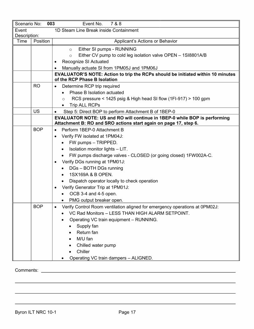
Comments: Byron ILT NRC 10-1 Page 17
Scenario No: 003 Event No. 7 & 8 Event Description:
1D Steam Line Break inside Containment
Time Position Applicant’s Actions or Behavior
o Either SI pumps - RUNNING o Either CV pump to cold leg isolation valve OPEN – 1SI8801A/B
• Recognize SI Actuated • Manually actuate SI from 1PM05J and 1PM06J
EVALUATOR’S NOTE: Action to trip the RCPs should be initiated within 10 minutes of the RCP Phase B Isolation
RO • Determine RCP trip required • Phase B Isolation actuated o RCS pressure < 1425 psig & High head SI flow (1FI-917) > 100 gpm • Trip ALL RCPs
US • Step 5: Direct BOP to perform Attachment B of 1BEP-0 EVALUATOR NOTE: US and RO will continue in 1BEP-0 while BOP is performing
Attachment B: RO and SRO actions start again on page 17, step 6. BOP • Perform 1BEP-0 Attachment B
• Verify FW isolated at 1PM04J: • FW pumps – TRIPPED. • Isolation monitor lights – LIT. • FW pumps discharge valves - CLOSED (or going closed) 1FW002A-C.
• Verify DGs running at 1PM01J: • DGs – BOTH DGs running • 1SX169A & B OPEN. • Dispatch operator locally to check operation
• Verify Generator Trip at 1PM01J: • OCB 3-4 and 4-5 open. • PMG output breaker open.
BOP • Verify Control Room ventilation aligned for emergency operations at 0PM02J: • VC Rad Monitors – LESS THAN HIGH ALARM SETPOINT. • Operating VC train equipment – RUNNING.
• Supply fan • Return fan • M/U fan • Chilled water pump • Chiller
• Operating VC train dampers – ALIGNED.

Comments: Byron ILT NRC 10-1 Page 18
Scenario No: 003 Event No. 7 & 8 Event Description:
1D Steam Line Break inside Containment
Time Position Applicant’s Actions or Behavior
• M/U fan outlet damper – NOT FULLY CLOSED. • VC train M/U filter light – LIT.
• Operating VC train Charcoal Absorber aligned • Bypass damper - CLOSED • Inlet damper - OPEN • Outlet damper - OPEN
• Control Room pressure greater than +0.125 inches water on 0PDI-VC038. • Verify Auxiliary Building ventilation aligned at 0PM02J:
• Two inaccessible filter plenums aligned. • Plenum A or B or C:
• Fan - RUNNING • Flow Control damper - OPEN • Bypass Isolation damper - CLOSED
• Plenum A or B or C: • Fan - RUNNING • Flow Control damper - OPEN • Bypass Isolation damper - CLOSED
• Verify FHB ventilation aligned at 0PM02J: • Fan - RUNNING • Inlet Isolation damper - OPEN • Flow Control damper - OPEN • Bypass Isolation damper – CLOSED
EVALUATOR NOTE: The remaining steps of Attachment B may be designated to be
performed by WEC personnel or the Field Supervisor and extra operators. o Trip all running HD Pumps
o Shutdown FW pump as necessary using BOP FW-2 for a TDFP or BOP FW-8 for the MDFP
o Shutdown unnecessary CD/CB Pumps using BOP CD/CB-2 o Align SX MDCT per BOP SX-T2
o Maintain SX Basin level > 80% o Align NDCT
o Verify CW intake bay level within band o Dispatch operator to locally verify NDCT basin level acceptable

Comments: Byron ILT NRC 10-1 Page 19
Scenario No: 003 Event No. 7 & 8 Event Description:
1D Steam Line Break inside Containment
Time Position Applicant’s Actions or Behavior
o Align NDCT per BOP CW-25 o Shutdown all unnecessary CW pumps per BOP CW-2 • Initiate periodic checking of Spent Fuel Cooling o Notify US of actions taken, equipment status, and that Attachment B is complete
RO/ BOP
• Step 6: Verify ECCS pumps running • Both CV pumps – RUNNING • Both RH pumps – RUNNING • Both SI pumps – RUNNING
BOP/ RO
• Perform the following at 1PM06J: • Step 7: Verify RCFCs running in Accident Mode:
• Group 2 RCFC Accident Mode lights – B and C RCFCs are not running in accident Mode
• Stop any RCFC running in High speed • Close CNMT chiller inlet and outlet valves 1SX112B/114B • Open CNMT chiller bypass valve 1SX147B o Open 1SX016B and 027B
o Start all RCFCs in low speed: NOTE to Evaluator: RCFC B and C will NOT start • Step 8: Verify Phase A isolation:
• Group 3 Cnmt Isol monitor lights – ALL LIT. • Step 9: Verify Cnmt Vent isolation:
• Group 6 Cnmt Vent Isol monitor lights – ALL LIT. BOP/
RO • Step 10: Verify AF system:
• AF pumps – BOTH AF pumps RUNNING. • AF isolation valves – 1AF13A-H OPEN. • AF flow control valves – 1AF005A-H THROTTLED.
• Step 11: Verify CC pumps – BOTH RUNNING. • Step 12: Verify SX pumps – BOTH RUNNING. • Step 13: Check if Main Steamline Isolation –required:
o 1D SG pressure < 640 psig (at 1PM04J) o CNMT pressure > 8.2 psig. o Verify MSIV and Bypass Valves – CLOSED
EVALUATOR’S NOTE: CS may have an actuation signal at this time. If it has not, the crew must return to this step to verify proper alignment when CNMT pressure exceeds 20 psig. CS will NOT automatically actuate and must be

Comments: Byron ILT NRC 10-1 Page 20
Scenario No: 003 Event No. 7 & 8 Event Description:
1D Steam Line Break inside Containment
Time Position Applicant’s Actions or Behavior manually actuated.
BOP/ RO [CT] E-0--E
• Step 14: Check if CS is required. • CNMT pressure has risen > 20 psig. • Group 6 CS monitor lights – NOT ALL LIT.
• Manually actuate CS and Phase B Isolation • Go to Attachment C
o Check CS001A OPEN • OPEN 1CS007A • 1CS019A is NOT OPEN
• Place 1A CS pump test switch in TEST • OPEN 1CS019A • Place 1A CS pump test switch in NORMAL • OPEN 1CS010A • Check 1A CS pump Running
• Group 6 phase B lights – LIT • Verify/Stop ALL RCPs (at 1PM05J). • CS eductor suction flows - > 15 gpm • CS eductor additive flows - > 5 gpm • Align SX Towers
• All 8 Riser valves OPEN • All 4 Bypass valves CLOSED • All 8 fans running in HIGH speed
CREW • Recognize and announce ADVERSE CNMT BOP/
RO • Step 15: Verify Total AF flow:
• AF flow > 500 gpm • S/G NR levels – NOT rising in an uncontrolled manner
RO/
BOP
• Step 16: Verify ECCS valve alignment • Determine Group 2 Cold Leg Injection monitor lights required for injection - All lit
RO/
BOP • Step 17: Verify ECCS flow
• High Head SI flow >100 gpm (1FI-917) • When RCS pressure < 1700 psig

Comments: Byron ILT NRC 10-1 Page 21
Scenario No: 003 Event No. 7 & 8 Event Description:
1D Steam Line Break inside Containment
Time Position Applicant’s Actions or Behavior
• BOTH SI pump discharge flows > 200 gpm • RCS pressure > 325 psig
RO • Step 18: Check PZR PORVs and SPRAY VALVES at 1PM05J: • 1RY455 & 1RY456 CLOSED • PORV isol valves – 1RY8000A & 1RY8000B BOTH ENERGIZED • PORV relief path – Both PORVs in AUTO, Both isolation valves – OPEN. • Normal PZR Spray Valves CLOSED
RO • Step 19: Maintain RCS temperature control at 1PM05J: • Check RCP’s – NONE RUNNING. • Verify RCS cold leg temperature stable at or trending to 557oF. • Throttle AF maintaining >500 GPM until SG minimum level is met o AF flow to 1D SG may be throttled to 0 GPM • MSIVs closed
RO • Step 20: Check status of RCPs at 1PM05J: o All RCP’s – NONE RUNNING. o Any RCPs still running – TRIP All RCPs IF Phase B isolation occurred or RCS
pressure trip criteria is met BOP/
RO • Step 21: Check if SG secondary pressure boundaries are intact at 1PM04J:
• Check pressure in all SGs: • 1D SG dropping in an uncontrolled manner.
CREW • Transition to 1BEP-2, ‘FAULTED STEAM GENERATOR ISOLATION’
US • Notify SM of plant status and procedure entry.
• Request evaluation of Emergency Plan conditions. • Request STA evaluation of status trees. • Enter/Implement 1BEP-2 and direct operator actions of 1BEP–2 to establish the
following conditions.
RO/ BOP
• Check MS isolation at 1PM06J: • All MSIVs and bypass valves – CLOSED
BOP • Check if any SG secondary pressure boundary is intact at 1PM04J: • 1A, 1B, & 1C SG pressures stable.

Comments: Byron ILT NRC 10-1 Page 22
Scenario No: 003 Event No. 7 & 8 Event Description:
1D Steam Line Break inside Containment
Time Position Applicant’s Actions or Behavior
CREW • Identify faulted SG at 1PM04J:
• 1D SG pressure decreasing in an uncontrolled manner. RO/ BOP
[CT] E-2--A
• Isolate 1D Steam Generator at completion of step 4 of 1BEP-2: • Verify/close 1AF013D & H at 1PM06J • Bottom row of FW isolation monitor lights – lit. • 1MS018D closed. • 1SD002C & D closed. • 1SD005B closed.
CREW • Monitor AF pump suction pressure. • Annunciator AF PUMP SX SUCTION VLVS ARMED (1-3-E7) – NOT LIT.
CREW • Determine 1D S/G tubes are intact: • Reset Phase A isolation • Open 1SD005A-D • Request Chemistry Dept samples all SG for activity • Check there are NO RM-11 or HMI Rad Monitor ALERT/HI RAD Alarms.
o 1PR27J SJAE/GS 1PR08J SG Blowdown. o 1PR08J SG Blowdown. o 1AR 22/23D 1D Main steam Line o Secondary activity samples normal (when available)
CREW • Check if ECCS flow should be reduced • RCS subcooling –ACCEPTABLE • Secondary heat sink-total feed flow to INTACT SGs > 500 GPM or NR level in
at least 1 SG > 10% (31% Adverse CNMT) • RCS pressure – stable or rising • Pzr level - > 12% (28% Adverse CNMT)
• Determine transition to 1BEP ES-1.1, SI TERMINATION
CREW • Transition to 1BEP ES-1.1, SI TERMINATION At lead Evaluators discretion the scenario may be terminated here. SI Termination
steps are contained in the next two pages up to securing the CS pump.

Comments: Byron ILT NRC 10-1 Page 23
Scenario No: 003 Event No. 7 & 8 Event Description:
1D Steam Line Break inside Containment
Time Position Applicant’s Actions or Behavior
US • Notify SM of plant status and procedure entry. • Request evaluation of Emergency Plan conditions. • Enter/Implement 1BEP ES-1.1 and direct operator actions of 1BEP ES-1.1
RO/ BOP
• Reset SI • Depress both SI reset PB • Verify SI Actuated light – NOT LIT • Very Auto SI Blocked light - LIT
RO/ BOP
• Reset Cnmt Isolation • Reset Phase A • Reset Phase B
BOP • Establish IA to CNMT • Check SACs – ANY Running • Open 1IA065 and 1IA066
RO/ BOP
• Realign CV Pump • Stop all but one CV pump
CREW • Check RCS pressure – Stable or rising
RO/ BOP
• Terminate High-head SI • CV pump suction aligned to RWST • Reset SI recirc sump isolation valves – 1SI8811A & B and 1CV8110 & 1CV8111 • Reset CV pump miniflow valves – 1CV8114 and 1CV8116 • Verify CV pump miniflow valves – OPEN • Close CV injection valves – 1SI8801A & B
RO/ BOP
• Establish Charging Flow • Place 1CV182 at 0% demand • Open CNMT isolation valves 1CV8105 and 1CV8106 • Set seal injection flow to 8-13 GPM per RCP
RO/ BOP
• Control Charging flow to maintain Pzr level stable
RO/ BOP
• Check if SI pumps should be stopped • RCS pressure – Stable or rising and > 1700 PSIG • Stop BOTH SI pumps and place in standby

Comments: Byron ILT NRC 10-1 Page 24
Scenario No: 003 Event No. 7 & 8 Event Description:
1D Steam Line Break inside Containment
Time Position Applicant’s Actions or Behavior • Step 10: Check if RH pumps should be stopped
• Any running with suction aligned to RWST • Stop both RH pumps and place in standby
• Verify ECCS flow not required • Subcooling acceptable • PZR level > 12% (28% adverse)
• Check if CS should be stopped • Reset CS signal • Close 1CS019B • CNMT pressure less than 15 psig • Stop 1B CS pump and place in standby • Verify 1CS019B closed • Close 1CS007B
EVALUATOR NOTE: The scenario can be terminated.