2012€¦ · engine compressor core consists of four axial compressor “blisks” (i.e.,...
16
HTF7000 Engine Design, Development and Uses David K. Winstanley Honeywell International Presented at: SAE 2013 AeroTech Congress & Exhibition Montreal, Canada September 25, 2013 2013-01-2228 CLIFF GARRETT TURBOMACHINERY ENGINEERING AWARD 2012 Downloaded from SAE International by David Winstanley, Monday, August 24, 2015
Transcript of 2012€¦ · engine compressor core consists of four axial compressor “blisks” (i.e.,...

HTF7000 Engine Design, Development and Uses
David K. Winstanley Honeywell International
Presented at:SAE 2013 AeroTech Congress & Exhibition
Montreal, CanadaSeptember 25, 2013
2013-01-2228
Cliff GarrettturbomaChinery
enGineerinG aWarD
2012
Downloaded from SAE International by David Winstanley, Monday, August 24, 2015

CliFF GarrETT TUrbomaCHinEry EnGinEErinG awarD
DescriptionThis award promotes engineering developments and the presentation of SAE papers on turbomachinery and/or developments that enable or advance the use of turbomachinery. The award honors Cliff Garrett and the inspiration he provided to engineers by his example, support, encouragement, and many contributions as an aerospace pioneer. To perpetuate recognition of Mr. Garrett’s achievements and dedication as an aerospace pioneer, SAE administers an annual lecture by a distinguished authority in the engineering of turbomachinery and/or engineering related to creating, enabling, or advancing applications of turbomachinery in power systems, on-highway, off-highway, aircraft, and/or spacecraft uses.
The awardThis award, established in 1984, is administered by the Garrett Award Selection Committee and consists of a framed certificate, a commemorative gift and an honorarium. The award is made possible by a contribution from the Garrett Corporation (now a division of Honeywell).
The lecture honors the memory of Cliff Garrett, an Aircraft pioneer and entrepreneur. Under Cliff’s leadership, Garrett was the first to build small auxiliary power gas turbines. One APU series that Cliff’s engineers started in the 1950’s is still in production today. This is the 85 series, a product that has outlived the company that bore Cliff’s name.
Although Garrett ceased to exist as a corporation in late 1987, individual Garrett divisions thrived under the AlliedSignal Aerospace banner until its acquisition by Honeywell. These divisions include the Phoenix-based Garrett Auxiliary Power Division and the Garrett Engine Division, which produce APUs and propulsion engines respectively.
Cliff had an overriding determination to see his company established as a propulsion engine supplier. This was just beginning to happen when he died in 1963. Cliff’s successor made that goal a reality. Cliff had an intensity and drive that were unequaled. He built Garrett from ground zero to a billion dollar company. Growth from within was achieved by product engineering innovation, as well as by a strong and dedicated sales team. Cliff represented a personalized, hands-on leadership style that was just right for his time and his company. We will always need leaders of his spirit and vision.
The Garrett Award Selection Committee welcomes nominations for future lectures and suggestions for subject matter related to the basic objective of the program. Nominations and suggestions may be emailed to [email protected]. For additional award information, please visit http://www.sae.org/news/awards/list/garret/.
awarD rECipiEnTs2013 David K.Winstanley2011 Bernard L. Koff2010 None2009 Dr. James W. Fuller2008 Dr. David Japikse2007 Vern E. Brooks2006 V. Ganesan2005 John J. Adamczyk2004 Dr. Ramesh Rajagopalan2003 Steven D. Arnold2002 Vincent A. Pedotto2001 Carl Schopfer2000 Barry Weinstein1999 Robert Lorimer1998 Eugene D. Jackson III
1997 J. P. (Jean-Paul) Frignac1996 None1995 Heinz F. Moellmann1994 Frank C. Gillette, Jr.1993 John Acurio1992 M. L. (Joe) Stangeland1991 John L. Mason1990 John D. Denton1989 Calvin L. Ball1988 F. Blake Wallace1987 Colin Rodgers1986 Arthur J. Wennerstrom1985 Frank E. Pickering1984 David P. Kenny
Downloaded from SAE International by David Winstanley, Monday, August 24, 2015

CliFF GarrETT TUrbomaCHinEry EnGinEErinG awarD
2012 Recipient
David K. winstanley Honeywell aerospace
David K. Winstanley is currently the Director of Mechanical Chief Engineers for Honeywell Aerospace. Mr. Winstanley is responsible for managing all Chief Engineers who provide design approval and safety review for all Honeywell mechanical products. Mr. Winstanley has previously been responsible as Senior Chief Engineer for developing and installing integrated mechanical systems for the Airbus A350 extended mechanical systems perimeter (EMSP) and JSF/F35 power and thermal management system (PTMS).
Mr. Winstanley was also, as Chief Engineer for Commercial Propulsion Engines, responsible for the design, development, certification and fielding of the HTF7000 turbofan engine.
Mr. Winstanley received BSME & MSME degrees from Purdue University. Mr. Winstanley is a proud member of SAE International.
Downloaded from SAE International by David Winstanley, Monday, August 24, 2015

Downloaded from SAE International by David Winstanley, Monday, August 24, 2015

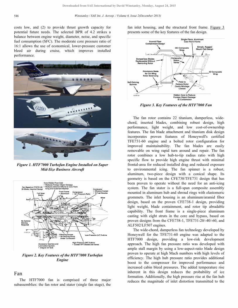
ENGINE FAMILYThe HTF7000 engine is the commercial name for a family
of engine specifically designed for the super-mid-sizedbusiness jet. The HTF 7000 powers the BombardierChallenger C300; the HTF7250 powers the Gulfstream G280;and the HTF7500 is proposed to power the Embraer Legacy450. These engines installed on their respective aircraft areshown in Figure 1.
The HTF7000 family is certified with the FAAdesignation of AS907 and produces maximum takeoff thrustin the range of 6500 to 7800 lbf. The engine certified ratingsare presented in Table 1. The HTF7500 is thermodynamicallylarger than the other two engines, but the specifics of the flatranging scheme lead to the specific certification ratings in thetable.
Table 1. HTF7000 Engine Family Type DesignComparison (Sea Level Static (SLS) Uninstalled
Conditions)
ENGINE OVERVIEWThe HTF7000 is a 4.2 BPR, two-spool, co-rotating
turbofan engine featuring a simple design (see Figure 2). It
derives its thrust from a single-stage, wide-chord, damperless,high efficiency, inserted-blade fan rotor that is driven directlyby an uncooled three-stage low pressure turbine (LPT). Theengine compressor core consists of four axial compressor“blisks” (i.e., integrally bladed disks) with two stages ofvariable and three stages of non-variable axial vanes; and asingle-stage centrifugal compressor. The axial and centrifugalcompressor rotors are driven by a two-stage, cooled high-pressure (HP) turbine (HPT). The HP and LP spools rotate inthe same direction.
The entire rotating system is supported by a bearing andseal system containing only two sump areas, both of whichare located in cool environments (i.e., no sump under thecombustor). The combustor is a through-flow, annular,effusion-cooled configuration. To reduce noise and improveefficiency, a forced mixer is used to merge the fan bypass andcore flows together prior to their exiting the engine through aconverging-diverging nozzle embedded in the thrust reverser.The engine includes the full-authority digital electroniccontrol (FADEC) system, which features dual channelelectronic control in the form of two independent electroniccontrol units (ECUs); the customer bleed system, providingtwo sources of bleed air sources to the aircraft; and theaccessory gearbox (AGB), which is designed toaccommodate airframe needs for such accessories as thegenerator and hydraulic pump.
The design approach for the HTF7000 enginesincorporated two major objectives: (1) to maintain turbinetemperatures at a level that precludes the use of exoticmaterials and thereby keeps maintenance and acquisition
2013-01-2228Published 09/17/2013
Copyright © 2013 SAE Internationaldoi:10.4271/2013-01-2228
saeaero.saejournals.org
HTF7000 Engine Design, Development and UsesDavid K. Winstanley
Honeywell Aerospace
ABSTRACTHoneywell has developed a unique turbofan engine for application to the super mid-size business aviation market, the
HTF7000. This paper will describe the design of this engine including aeromechanical design of its components. Theunique design features of this engine will be described along with the technology growth path to keep the engine current.This paper will also describe several features which have been developed for this engine in response to new regulatoryrequirements. Some aspects of the engine to aircraft integration will also be described.
CITATION: Winstanley, D., "HTF7000 Engine Design, Development and Uses," SAE Int. J. Aerosp. 6(2):2013, doi:10.4271/2013-01-2228.
____________________________________
545
Downloaded from SAE International by David Winstanley, Monday, August 24, 2015
costs low, and (2) to provide thrust growth capacity forpotential future needs. The selected BPR of 4.2 strikes abalance between engine weight, diameter, noise, and specificfuel consumption (SFC). The moderate core pressure ratio of16:1 allows the use of economical, lower-pressure customerbleed air during cruise, which improves installedperformance.
Figure 1. HTF7000 Turbofan Engine Installed on SuperMid-Size Business Aircraft
Figure 2. Key Features of the HTF7000 TurbofanEngine
FanThe HTF7000 fan is comprised of three major
subassemblies: the fan rotor and stator (single fan stage), the
fan inlet housing, and the structural front frame. Figure 3presents some of the key features of the fan design.
Figure 3. Key Features of the HTF7000 Fan
The fan rotor contains 22 titanium, damperless, wide-chord, inserted blades, combining robust design, highperformance, light weight, and low cost-of-ownershipfeatures. The fan blade attachment and titanium disk designincorporates proven features of Honeywell's certifiedTFE731-60 engine and a bolted rotor configuration forimproved maintainability. The fan blades are easilyremovable on wing rapid turn around and repair. The fanrotor combines a low hub-to-tip radius ratio with highspecific flow to provide high engine thrust with minimalfrontal-area for reduced installed drag and reduced exposureto environmental icing. The fan spinner is a robust,aluminum, two-piece design with a conical shape. Itsgeometry is based on the CFE738/TFE731 design that hasbeen proven to operate without the need for an anti-icingsystem. The fan stator is a full-span composite assemblymounted in aluminum hub and shroud rings with elastomericgrommets. The inlet housing is an aluminum/aramid fiberdesign, based on the proven CFE738-1 design, providinglight weight, blade containment, and rotor tip abradablecapability. The front frame is a single-piece aluminumcasting with eight struts in the core and bypass, based onproven designs from the CFE738-1, TFE731-20/-40/-60, andALF502/LF507 engines.
The wide-chord, damperless fan technology developed byHoneywell for the TFE731-60 engine was adapted to theHTF7000 design, providing a low-risk developmentapproach. The high fan pressure ratio was developed withample stall margin by using a low-aspect-ratio blade designproven to operate at high Mach numbers with high levels ofefficiency. The high hub pressure ratio provides additionalboost to the compressor for improved performance andincreased cabin bleed pressures. The added temperature riseinherent in this design reduces the probability of iceformation. Additionally, the high pressure rise at the fan hubreduces the magnitude of inlet distortion transmitted to the
Winstanley / SAE Int. J. Aerosp. / Volume 6, Issue 2(December 2013)546
Downloaded from SAE International by David Winstanley, Monday, August 24, 2015

core compressor, resulting in improved compression systemstability.
The HTF7000 fan blade containment system uses analuminum honeycomb material surrounded by a simplearamid fiber wrap for the optimum balance of light weightand containment capability. This configuration is used in theCFE738 engine. The structural front frame uses castaluminum technology similar to that used in Honeywell'sTFE731-20/-40/-60, CFE738, and ALF502/LF507 engines.The position of the front frame flow-path splitter relative tothe rotor trailing edge is prescribed by trajectory analysispredictions for objects (birds, ice, inclement weather, etc.)ingested by the fan. The result is a well-hidden core flow-path inlet, reducing the potential for foreign object damage(FOD) to the core, and eliminating the need for any anti-icingsystem for the engine.
The HTF7000 fan mechanical support incorporates afrangible support in the No.1 bearing region. The frangiblesupport is designed to maintain structural support andstiffness during normal operation and during a 1½- or 4-pound bird ingestion event, and to preclude excessive loadsfrom being transmitted into the front frame structure during afan blade-out event. Once a predetermined radial load isreached, the frangible link shears, permitting the fan to seek anew center of rotation without transmitting the full loadsfrom the event into the surrounding structure, inlet, or enginemounts. Fan motion is limited, radially and axially, by thebearing support structure. The frangible support effects bettercontrol over the maximum load during a severe load event,thereby achieving better structural integrity.
The unheated conical spinner is based on the TFE731 andCFE738 turbofan engines. Over 7,200 Honeywell engines arein service with unheated conical spinners, havingaccumulated over 35 million cumulative hours of operation.No reported engine damage due to ice ingestion and noknown anomalies regarding engine operation in icingconditions have been recorded for Honeywell enginesconfigured with unheated conical spinners.
The fan blades were designed to maintain sufficientfrequency margin on all critical resonances and to ensureblade strength and reliability relative to bird impactrequirements.
CompressorThe HTF7000 high-pressure compressor consists of three
major subassemblies: a four-stage axial compressor, a singlestage centrifugal compressor, and supporting structure. TheHTF7000 compressor design built on a successful advancedtechnology development and validation effort (knowncolloquially as the AS900TVT) in which the baseline designsand technologies were demonstrated in a core engine. Boththe A900TVT and the HTF7000 compressor designemphasized robustness and low parts count for improvedreliability and cost of ownership. Key features and attributesof the compressor are shown in Figure 4.
Figure 4. Key Features of the HTF7000 Compressor.
The compressor rotor assembly includes four blisk rotors,the associated spacers, and the impeller, primarily connectedvia curvic couplings. The blisks and impeller airfoils are“flank milled” for improved producibility. The axialcompressor stationary components consist of five vane rowsand the compressor cases. The first two vane rows, the inletguide vane (IGV), and the first stage stator are variable topermit the engine control system to maintain goodcompressor performance and operability margin at part speedconditions. The compressor variable geometry (CVG) islocated in a manner that shields the components from adverseenvironmental conditions and is designed for long life. Theother vane rows are integrally cast in 360-degree rings. Theaxial compressor stages have abradable blade track coating toaccommodate blade tip incursions and maintain goodcompressor performance. To maximize compressor efficiencyand stabilize the operating range, each of the four axialcompressor stators has an inner-band abradable seal toaccommodate the rotating labyrinth seal knives in restrictingreverse-flow leakage. The axial and centrifugal compressorsare mounted on the common HP spool shaft. The impellerdischarge flow passes through a radial diffuser, a 120-degreeflow-path bend, and a tandem deswirl vane assembly thatdirects the low-velocity, high-pressure airflow to thecombustor.
Materials selected for the HTF7000 compressor rotors areforged titanium for light weight and corrosion resistance. TheIGV and first stage stator are fabricated from forged stainlesssteel, and the later stage axial stators are fabricated from castnickel-base material. The IGV inner and outer, and the firststage inner, vane supports are fabricated from aluminum. Thecompressor case and shroud system incorporates the widelyused titanium and nickel-base materials; titanium is used onlyover the first stage rotor, while nickel-based material is usedover the remaining axial stages and the impeller. Abradablecoatings are applied to the axial compressor shrouds to ensureoptimum blade-tip running clearances and componentreparability.
Winstanley / SAE Int. J. Aerosp. / Volume 6, Issue 2(December 2013) 547
Downloaded from SAE International by David Winstanley, Monday, August 24, 2015

A close-coupled aero-mechanical optimization systemused for the compressor design ensured an optimum solution.The HTF7000 design has lower loadings, which translate intohigher surge margin when compared with similar Honeywelldesigns. Three-dimensional single-blade-row and multistageviscous analyses were used to determine the operabilitycharacteristics of the compressor. In addition, flutter analysiswas conducted on the rotor airfoils, verifying that the designis free of flutter. The compressor is designed in a manner thathides its inlet from most of the particles entrained in the fandischarge flow stream, minimizing exposure of the enginecore to FOD, ice, and inclement weather. The diffusionsystem consists of a radial diffuser and a tandem deswirl thattogether deliver flow to the combustor with almost noresidual swirl and at low Mach numbers.
CombustorThe HTF7000 combustor consists of a combustion
chamber (combustor), fuel nozzles, igniters, and a plenum.The combustor is effusion cooled to provide low metaltemperatures for long life. Significant effort was focused onlow cost and producibility, with the resulting featuresincorporated into the combustor design, such as machinedswirler assemblies, simplified fuel nozzles, and rapid lasereffusion drilling.
The HTF7000 combustor is sized to attain minimum cold-side pressure loss in the flow annulus, thus using the majorityof available pressure loss across the combustor for mixingfuel and air and for controlling pattern factor. Combustorairflow distribution is optimized for efficient combustion, lowpattern factor, altitude light-off, and emissions usingHoneywell's 3-D computational fluid dynamic (CFD)combustor performance flow model, which has beenvalidated on various prior combustor designs. The combustorflow-path design and the fuel nozzle and swirler combinationwere designed to uniformly mix the fuel and air. Thisuniform mixing eliminates circumferential hot streaks, whilepreventing fuel impingement on the combustor walls and anypotential carbon formation.
To achieve long time combustor lives, two major featureswere incorporated into the HTF7000 design. One of these iseffusion cooling with thermal barrier coating (TBC), selectedfor temperature control. Effusion cooling is used for all newcombustor designs at Honeywell, and is currently used on theTFE731-20/-40/-60 engines, the CTS800 engine, the RE220and 331-500 auxiliary power units (APUs), and the LT101propulsion engine. The other major feature for achieving thelife goal is the use of Haynes 230 material.
The HTF7000 fuel injection design optimizes sprayquality for ignition and uniform flow matching at alloperating conditions through the combination of 12 pureairblast fuel nozzles and 4 dual-circuit start nozzles. Thesystem was based on technology available from the TFE1042engine, and successfully demonstrated successful and reliablestarting to an altitude above 30,000 feet. The HTF7000combustor is designed for robust lean stability, with sufficient
margin to avoid the pressure fluctuations encountered when acombustor is operated too near lean blowout.
The HTF7000 engine incorporates an ecology and flowdivider valve in the fuel supply to the fuel nozzles. Duringengine shutdown, the ecology and flow divider valve pistonpulls the fuel from the fuel nozzles and holds it until the nextstart, thereby preventing the fuel nozzle coking that wouldnormally occur during engine shutdown and soakback. Thisapproach was chosen also to provide environmental value bypreventing the fuel remaining downstream of the controlvalves from evaporating into the atmosphere as was commonin older engines.
As described in reference [1], smaller engines (< 9,000lbsthrust class), and especially those designed for business jetapplications have a more difficult problem statement inachieving emissions requirements. The HTF7000 wasinitially certified to all relevant emissions requirements at thetime of certification; however, recognizing that theserequirements were changing in the near future and that engineand aircraft needed to demonstrated their environmentallyfriendly designs, Honeywell embarked on a technologydevelopment program to improve combustor emissionsspecifically minimizing and balancing nitrous oxides,unburned hydrocarbons, carbon monoxide, and smoke.
Figure 5. The Rich-Quench-Lean Combustor
Honeywell's approach to achieving these goals is calledSingle Annular comBustor for Emissions Reduction(SABER). SABER is tiered technology program designed todeliver improved combustion emissions over time while theengine grows. SABER has successfully employed the Rich-Quench-Lean (RQL) concept (illustrated in Figure 5). Thefirst tier (SABER-1) was completed and certified forincorporation into the HTF7000 engine in 2010. TheSABER-1 measured NOx emissions to be better than 27%margin to the ICAO CAEP/6 requirements, and has met allother operability and durability requirements for certification.
Winstanley / SAE Int. J. Aerosp. / Volume 6, Issue 2(December 2013)548
Downloaded from SAE International by David Winstanley, Monday, August 24, 2015

The key design features of this first tier SABER combustorare illustrated in Figure 6. The second tier SABER is wellunder way and expected shortly; in addition, Honeywell isapplying this technology to its auxiliary power units (APU) toreduce their emissions as well.
The initially certified HTF7000 combustor design madeextensive use of computational fluid dynamics (CFD), butvalidated those results with combustor rig testing. TheSABER combustor design has substantially benefitted fromadvances in modern CFD with the result being reducedtesting required. An example of the results of this CFD forthe SABER combustor is presented in Figure 7.
Figure 6. SABER-1 Geometry & Changes to AchieveEmission Targets
High Pressure TurbineThe HTF7000 high pressure turbine (HPT) is a two stage
turbine as shown in Figure 8. All four airfoils are actively andefficiently cooled. The disks are mated with seal plates thatallow cooling air to be delivered and provide positive axialretention of the blades. A tangential on-board injector (TOBI)system is used to efficiently deliver high pressure air to thefirst stage blade. The first stage and second stage HP statorsare cast and segmented. The blade tip shroud segments arecoated with TBC material on the gas-path side to reduceshroud temperatures and tolerate light blade rubs.
Materials selected for the HTF7000 HP turbine includeHoneywell's proprietary single-crystal material for the firststage blade, directionally solidified standard material for thesecond stage HP blade, specially processed Inconel 718 forthe rotor disks, and seal plates. Knife seals on the first stageseal plate and second stage HP seal-plate coupler are hard-coated for improved rub tolerance.
The turbine stators are cast equiaxed MAR-M 247 coatedwith diffused platinum aluminide. This material combinationhas been successful on the TFE731-4/-5 andTFE731-20/-40/-60 series engines. The cooling effectivenessdesigned for the HTF7000 ensures that vane and blade metaltemperatures are lower than targeted for similar materialcombinations in the TFE731 engines. The blade tip shroudsegments are made of IN738LC and HA-230, respectively,materials chosen for high-temperature creep strength andoxidation resistance. The tip shroud support structure is made
of Waspaloy, which provides the strength necessary for bladecontainment.
Figure 7. CFD predicted Temperature Contours at theFuel Injector Centerline comparing RANS and time-
averaged LES simulations
Figure 8. Key Features of the High Pressure Turbine
Cooling schemes used in the HTF7000 HP turbinemodule are those that are being successfully used on existingHoneywell production engines. Platform “bathtub” seals areused in both stages to minimize hot-gas ingestion into theattachment area, as well as to provide a vibration damping
Winstanley / SAE Int. J. Aerosp. / Volume 6, Issue 2(December 2013) 549
Downloaded from SAE International by David Winstanley, Monday, August 24, 2015

effect for the airfoil. The cooled stators for the HTF7000incorporate design and manufacturing concepts successfullyproven on the TFE1042 and TFE731-60 engines. The statorsare cast as segments to enable individual replacement.Impingement tubes fit in a core cavity of the airfoil allow foreffective cooling.
Low Pressure TurbineThe low pressure turbine is a three-stage rotor coupled
directly to the fan, designed for minimal parts count andincreased reliability. All blade stages have tip shrouds thatprovide vibration damping and tolerate light rubs without lossof performance. The turbine case configuration providesblade containment and is modeled after the proven CFE738configuration. The exit guide vane reduces losses as the hotgases leave the engine core, and also provides routing forservices required by the aft sump. There are no oil orscavenge services located between the HP turbine and the LPturbine; instead, they are supplied through the cooler exitguide vane. Key features of the HTF7000 LP turbine areshown in Figure 9.
The aft mount provisions consist of clevises that are partof the exit guide vane casting. There are four clevisesarranged for side mounting, two for the right-handinstallation and two (located on the opposite side) for the left-hand installation. The entire LP turbine can be removed orinstalled as a module. There are 17 borescope inspectionports in the turbine case for inspection of all three stages andthe trailing edges of the second stage HP blade. The entire LPturbine module can remain in place while the aft HP and LPbearings and seals are removed or installed.
Figure 9. Key Features of the Low Pressure Turbine
The material used in the LP turbine case affects overallengine cost, weight, and performance. The case functions asthe primary containment structure for the turbine, andcontrols blade-tip clearances for the first stage. IN718 waschosen as the case material for its containment capabilities,
though turbine case temperature was also a key factor in thematerial selection. Experience and low density dictated thechoice of IN100 for the HTF7000 LP turbine blades. The LPturbine disks are made of DP718. The disk forgings arefabricated using a “rolled ring” process, which yieldsproperties equal to or better than the standard “closed die”process. This rolled ring process is used for flanges on theTFE731 engines and for containment rings on APUs. Thedrive arm and rotating seal are fabricated from DP718forgings using the standard closed-die process. The statorsare cast, full-ring components fabricated from MAR-M 247(LPT1) and IN713LC (LPT2 and LPT3). The high strengthand castability of IN718 make it the best choice for the EGV.
The altitude cruise condition was selected as theaerodynamic design point for the HTF7000 LP turbine. Theengine specific-work requirement was met by designing athree-stage, moderately loaded turbine, and by selecting aturbine mean radius that would provide stage mean-workcoefficients well within Honeywell's range of experience. Thehigher mean radius allows the turbine to operate at a higherefficiency, and reduces the risk associated with a close-coupled, lower radius turbine. The turbine flow pathincorporates a long-chord EGV that results in a low airfoilcount.
Secondary Flow SystemThe HTF7000 secondary flow circuit is designed to
ensure proper cooling and purging of the turbine and sumpcavities. The system uses air from three sources-thecombustor plenum and Stages 3 and 4 axial compressordischarge to cool the HP and LP turbines.
The secondary flow system is designed to preclude thepassage of foreign matter of unacceptable quantity or size.The core inlet configuration is designed to prevent theingestion of large particles into the core by centrifugallyseparating these particles into the fan duct. Ingestion of smalldust and foreign matter is allowed due to the robust design ofthe secondary flow system. All orifices, includingimpingement and film cooling holes in the high pressureturbine blades, vanes, and insert tubes, are sized sufficientlylarge to preclude blockage by small foreign matter. Also,additional “dust holes” are designed into the high pressureturbine blade tips to prevent accumulation of dust in thecooling passages. This “particle vent” concept has beensuccessfully used on serpentine blade designs in Honeywell'sTFE1042, AGT1500, and ATF3-6 engines. The effectivenessof these features for the HTF7000 secondary flow system wasevaluated during engine endurance testing conducted inhaboob conditions at Honeywell's San Tan desert test facility.
The HP turbine is cooled using a combination of air fromaxial compressor discharge and compressor exit. Compressorexit air actively cools the first and second stage HP turbinevanes. For the first stage vanes, the air is fed through both theOD and ID walls of the vane; for the second stage HP vane,the air is fed through metering pins in the OD of the vane. Asmall quantity of the air entering the impingement tube of the
Winstanley / SAE Int. J. Aerosp. / Volume 6, Issue 2(December 2013)550
Downloaded from SAE International by David Winstanley, Monday, August 24, 2015

second stage HP vane is fed through the vane's inner end wallto purge the HPT interstage cavity. The HPT tip shrouds areimpingement cooled via holes in the shroud support using airfrom the compressor exit.
Cooling air for the first stage blade is fed through the inletinducer, which provides a preswirl for the air entering therotating feed cavity for the blade. The second stage HP bladeis cooled using air from the axial stage exit routed throughthe compressor shafting. This cooling air then passes betweenthe HPT rotors and the HP shaft to the aft end of the HPturbine. The first stage and second stage HP seal plates havepumping vanes to maximize pressure rise to the second stageHP blade.
The HPT disks and seal plates are cooled primarily by theblade cooling air, which passes radially outward between thedisks and seal plates. Additionally, the disks are cooled bycavity purge air in the interstage seal cavity. This interstagecavity purge air is supplied through the second stage HP vaneand is discharged into the first stage disk aft rim cavity. Thisaft rim cavity air is metered by machined orifices in thesecond stage HP vane feed system. After passing into the firststage rotor aft cavity, airflow is metered across the interstageknife seal, then purges and cools the forward side of thesecond stage HP disk. The cavity on the aft side of the secondstage HP seal plate is purged by LPT cooling air, which ismetered through holes in the LPT panel seal.
The low pressure turbine is cooled using air supplied fromaxial stage exit which is routed externally to the LPT case.An internal baffle mounted on the first stage LPT vaneassembly reduces heat transfer between the LPT cooling airand the hot surface of the duct outer flow path. After exitingthe LPT case plenum, the LPT cooling air passes through thefirst stage LPT vane into an annular plenum that feeds cavitypurge air to the aft face of the second stage HP seal plate andto the LPT1 rotor. An insulation blanket installed on the ID ofthe first stage LPT nozzle assembly flow path reduces heatabsorption by the LPT cooling air in this annulus.
Accessory Gearbox and Lubrication SystemThe self-contained, integral HTF7000 engine lubrication
system is based on other Honeywell production designs. Itsperformance has been enhanced by using the engine FADECsystem to monitor oil pressures and temperatures, control thechip detector debris-clearing function, and performdiagnostics through the engine condition and fault reportingsystem. The lubrication system is designed to lubricate andcool the bearings, oil seals, splines, and gears. A fine-mediaoil filter is incorporated to increase bearing and gear lives.Effective scavenging and venting of the bearing sumpsprevents oil churning and flooding of the bearings and seals.Air vented from the sumps is routed to the AGB, thenthrough a serpentine-type air/oil separator, and finally intothe nacelle drain mast. The accessory gearbox (AGB) takesadvantage of TFE731 and CFE738 accessory gearboxtechnology by using an oil tank integral with the accessorygearbox, thus keeping the number of external lines to a
minimum. The accessory pads incorporate non-contacting,lift-off face seals. A seal drain system is incorporated tocapture any oil leakage and route it to the engine nacelledrain system. The AGB is removable on wing withoutremoving the front frame or towershaft. The towershaft drivesystem transmits power from the engine HP spool to the AGBthrough the 6 o'clock strut of the engine front frame. Thetowershaft spline engagements are oil lubricated.
The oil supply system is an unregulated system with asimple, externally adjustable pressure adjusting valve. Oil istaken from the tank by a positive-displacement pump drivenoff the HP spool through the AGB, and passed through the oilfilter and into the fuel heater/oil cooler before being suppliedto the engine. A distribution network delivers oil to thevarious components via a series of metering orifices and jets.The system takes advantage of internally cored passageswherever possible to minimize the number of external pipesand fittings. Once the components have been lubricated andcooled, the oil is scavenged out by dedicated pump elements.This scavenge oil is directed through a full-flow, electronicchip detector to identify distress within the engine or AGB.The chip detector indication is transmitted via the FADEC tothe aircraft maintenance systems. The chip detectorincorporates a debris-clearing function to prevent nuisanceindications. Engine maintenance action is further isolatedtoward individual sumps via magnetic plugs (i.e., debrismonitors) installed in the respective sump scavenge passages.
The pumping elements for both the supply and scavengeoil circuits are based on gerotor configurations. Oil supply isprovided by two main elements, whereas a total of sixscavenge elements transfer oil back to the tank. A relief valveis incorporated in the oil filter module to limit elevated cold-start pressures. The oil pump drive-shaft bearings and splinesare positively lubricated by cooled, filtered oil.
The primary filter in the lubrication system is located inthe pressure pump discharge line. An aluminum filter bowlhouses both the element and the pressure differentialindicator. An impending filter bypass signal is transmitted viathe ECU. A bypass valve is incorporated to maintain oil flowto downstream components in the event the filter clogs, andto prevent contaminants from reentering the system. Duringbypass mode, the system still provides a minimum filtrationlevel by means of an accessible last chance screen. Externallyaccessible scavenge screens are also incorporated for addedsystem protection. The oil supply is routed through the fuelheater - oil cooler, which is located upstream of the fuel filterto provide effective fuel heating and preclude the need for aseparate fuel heater.
The HTF7000 AGB has pad and gear arrangements tomeet the specific customer requirements for aircraftaccessories (i.e., generator and hydraulic pump), speeds,rotations, and interfaces. The air/oil separator is common toall configurations, as are most of the bearings and seals. Theitems driven by both AGB configurations include thehydromechanical unit, permanent magnet alternator, cartridgeoil pump, aircraft generator, and aircraft hydraulic pump. The
Winstanley / SAE Int. J. Aerosp. / Volume 6, Issue 2(December 2013) 551
Downloaded from SAE International by David Winstanley, Monday, August 24, 2015

AGB incorporates quick-attach/detach connectors at the twocustomer accessory pads for ease of removing and installingthe aircraft generator and hydraulic pump. The AGB ismounted to the engine frame in a manner similar to theCFE738 AGB, with the addition of a redundant mount toprotect against the loss of a mount due to fire and astabilizing strut to reduce AGB vibration in extreme icingconditions. Lubrication of the AGB is accomplished by acombination of oil jets for the critical bearings and gears, andsplash lubrication for the other components. Baffles areinstalled around certain gears to minimize oil aeration andimprove oil scavenging. Sealing is accomplished usingnoncontacting, lift-off carbon face seals. The towershaftsystem is designed to transmit a static torque that is higherthan the actual maximum starting torque of the air turbinestarter, plus the normal running loads with all accessoriessimultaneously loaded. The towershaft system incorporatesthe conventional spiral bevel gear scheme at the compressorshaft and AGB input shaft.
Shafting and BearingsThe HTF7000 rotor dynamic system is based on the
TFE731, CFE738, and TFE1042 turbofan engines. The LPshaft system is supported by two roller bearings (Nos. 2 and5) and a thrust bearing (No. 1). The hard-mounted No. 2bearing in the LP rotor system positions the flexure criticalmode above operating speed to minimize vibration and toavoid non-synchronous excitation. The HP turbine rotorsystem is supported by the No. 3 ball bearing at the forwardend and by the No. 4 inter-shaft-mounted roller bearing at theaft end. The No. 1 and No. 5 bearings in the LP rotor systemand the No. 3 bearing in the HP rotor system have squeezefilm dampers that isolate the rotors from the supporthousings. The squeeze film dampers are optimized to providesoftness and damping for the rigid body modes below idlespeed.
There are three bearings in the engine forward sump. TheNo. 1 ball bearing supports the forward end of the LP fanshaft and provides axial thrust control. The No. 2 rollerbearing supports the forward radial load of the LP shaft. TheNo. 3 ball bearing supports the forward end of the HP rotorand the thrust load of the HP shaft. The bearing design valuesdo not exceed the bearing design experience of the CFE738and TFE1042 production engines.
The HTF7000 main-shaft seal designs are based onsuccessful CFE738, LF507, and TFE1042 engine designs. Allof the main shaft seals are buffered using interstagecompressor air to maintain a positive pressure differentialunder all engine operating conditions. Also, scavenging of thebearing compartment is configured to preclude oil buildupand prevent flooding at all attitudes within the flightenvelope. The carbon ring-to-shaft clearance is minimized athigh power levels, thereby limiting air leakage into the sump.
There are two cylindrical roller bearings in the engine aftsump. The No. 5 bearing supports the aft end of the LP shaftand the No. 4 bearing supports the aft end of the HP shaft.
The No. 4 bearing is an inter-shaft bearing, configured so thatthe inner ring mounts on the HP shaft and the outer ring fitsinto a spring cage attached to the LP shaft.
Buffering air for the seals is extracted from the interstagecompressor area and fed into the cavities outside the main-shaft seals to provide positive pressure differential across theoil seals and thereby prevent oil leakage. Buffering air isintroduced to the forward sump seals via individual corepassages inside the front frame. This buffering air purges theLP and HP shaft annulus to prevent oil leakage and coking.For the aft sump, No. 4 and No. 5 seals, a separate bufferingair line is provide externally. A feature of the HTF7000buffering system is the implementation of the double-drainlabyrinth system for the forward sump seals. This system islocated upstream of the aircraft cabin bleed ports, where anyoil leakage could result in bleed air contamination. Thedouble-drain system consists of a multiple series of labyrinthseals with a buffer air source supplied between the outerlabyrinth knives. Two oil drains are provided, one on theinboard side located in the air cavity of the carbon seal, andthe other on the outboard side located inside the bufferinglabyrinth seals. The drains purge any leaking oil into therespective cavities. The buffering system is also designed toprevent adverse pressure reversals across the seals duringengine startup, motoring, and shutdown.
Reference [2] provides insight into an interestingdevelopment issue with the HTF7000 engine - non-synchronous vibration of the rotor system. As illustrated inFigure 10 (from reference [2]), the engine experienced highlevels of vibration which did not correlate with any rotorspeed characteristic (i.e. non-synchronous) and occurred inthe high power, high speed operation regime. Theaerodynamic destabilizing force in the engine obviouslyexceeded the system damping resulting in a non-synchronouswhirl in the engine. Other contributing factors were found tobe the stiffness of inter-shaft bearing spring cage, LP and HProtor balance, inter-shaft bearing element internal clearance,No. 5 bearing squeeze film type and clearance, and No. 5bearing support stiffness. While non-synchronous vibration isa known phenomenon in the turbine engine industry, this wasHoneywell's first significant experience in resolving it. Theresolution took significant development effort and isillustrated in Figure 11. A specially designed centering springwas developed to support the No. 5 bearing. This design useda soft spring to enhance modal damping combined withanisotropic stiffness, with 2:1 stiffness split between verticaland horizontal direction to provide modal damping andsuppress instability. The anisotropy was achieved byasymmetrically arranging 6 beams. A bumper was added tolimit center spring deflection during maneuver and blade lossevents. Further, the centering spring forms the bearing outerrace to reduce internal clearance of the rollers and thecentering spring has an offset in the vertical direction tocenter the bearing under ‘1g’ load.
Winstanley / SAE Int. J. Aerosp. / Volume 6, Issue 2(December 2013)552
Downloaded from SAE International by David Winstanley, Monday, August 24, 2015

Figure 10. HTF7000 Non-synchronous VibrationMeasurements (Reference [2]).
Figure 11. Centering spring support for No. 5 bearingdesigned to eliminate non-synchronous vibration
Ducting & Thrust ReverserThe purpose of the HTF7000 ducting and exhaust system
is to control and direct engine airflow to produce thrust. Thesystem comprises an inner bypass fan duct, an outer bypassfan duct, a mixer, a centerbody, and thrust nozzleincorporated into the stowed thrust reverser. An explodedview of the ducting, along with other nacelle components,and the thrust reverser is shown in Figure 12. The fan ductsdirect the bypass fan airstream around the engine core, andthen the mixer and centerbody mix the core and bypassairstreams. The design of the forward outer and forward innerfan ducts, including airflow contours, external pass-throughs,and Zone 2 cooling scoops, is similar for all versions of theengine exhaust systems. Zone 1 is the area outboard of theouter fan duct and is the cold fire zone. Zone 2 is the areabetween the inner fan duct and the engine core, and is the hotfire zone.
The forward duct section is a single-piece aluminum casethat attaches at its forward interface to the engine front fanframe. The forward duct section incorporates removableaccess panels for maintenance of the core-mountedcompressor variable geometry actuator and surge bleedvalves, and for borescope inspection. The forward ductsection also incorporates fireproof bulkhead provisions in the6 and 12 o'clock struts for engine and aircraft services. Theaft duct section attaches to the forward outer fan duct sectionvia a flanged interface. The aft duct section comprises asupport structure and removable acoustic panels, the latterproviding noise attenuation as well as access for enginemaintenance and inspection. The aft duct section alsoincorporates provisions in the 6 o'clock strut for engine andaircraft services. The aft duct section serves as the interfaceattachment for either an airframe supplied thrust reverser orforward thrust nozzle, both designated as aircraft-certifiedcomponents. The outer fan duct is the firewall between Zones1 and 2. All duct materials are fireproof, as are the seals,where necessary. The seals protect against fluid and airleakage.
Figure 12. Exploded view of HTF7000 engine showingducting, nacelle components, and thrust reverser.
The nacelle components (inlet, fan cowl doors, Part 25engine build unit) plus the fan bypass ducting were designed,built, and tested by GKN Aerospace for the HTF7000. Thethrust reverser was designed, built, and tested by Aircelleunder contract to GKN and certified with the aircraft. Thethrust reverser is illustrated in Figure 13. It is of some interestthat Honeywell, GKN, and Aircelle completed sufficientanalysis and testing that the thrust reverser to providesufficient confidence such that the thrust reverser wasdeployed and used during landing on the first flight of theChallenger 300.
Control SystemThe engine is controlled by a dual-channel full authority
digial electronic control (FADEC) system that is mounted onthe engine (see Figure 12). There are two separately packaged
Winstanley / SAE Int. J. Aerosp. / Volume 6, Issue 2(December 2013) 553
Downloaded from SAE International by David Winstanley, Monday, August 24, 2015

ECUs, in cast aluminum housings, plus associated sensors,actuators, and igniters, and the interconnecting wireharnesses. The FADEC system controls fuel flow, variablegeometry, and surge bleed. The system also integratespowerplant monitoring and signal conditioning, and controlor monitoring of other engine systems, including operation ofthe chip detector/zapper. Control of the thrust reverser isshared by the aircraft and the FADEC system, such that thepowerplant alone cannot deploy the thrust reverser.
The FADEC system uses dual engine signals and dualactuation signals. There is a cross-channel data link betweeneach channel on each engine, and two crossengine data linksbetween the left channels of the two engines and the rightchannels of the two engines. Sensors are generally dualwound (separate inputs to each channel), and actuators arecontrolled by dual-coil torque motors. Certain sensors aresingle element with resistor and/or diode isolation. Eachchannel contains overspeed protection against control systemoverfueling failures. The overspeed protection circuits in eachchannel are independent of each other and the centralprocessing unit, and each is capable of shutting off fuel in theevent overspeed is detected. The FADEC system alsoincludes a permanent magnet alternator which powers thecontrol electrical and electronic components and systemindependent from the aircraft. A vibration sensor andmonitoring system in FADEC conditions the signal toprovide for cockpit annunciation and for ground-based fantrim balance.
Figure 13. Installed and deployed thrust reverser forHTF7000.
Certification & Flight TestThe certification test program comprised 22 engine tests,
20 rig tests, and 34 component tests, the former contributingto the total of over 19,000 hours of full-scale engine testing(development and certification) completed at the time of typecertification.
In addition to the usual exciting tests (fan blade out, 4 lbbird ingestion), the HTF7000 was the first engine to complete
multiple 1.5 lb bird ingestion testing with the (then) new runon requirements (roughly 75% thrust for 20mins withthrottles moving). Similarly, the HTF 7000 successfullypassed a severed shaft test - a first for Honeywell at the time.
As illustrated in Figure 14, Honeywell concluded thatspecialized flight testing was a preferred approach overaltitude tank testing to achieve both development andcertification altitude testing. A more detailed presentation ofthis flight test capability can be found in Reference [3].
Figure 14. Honeywell's flight test vehicles forcertification and endurance flights:B720 with HTF7000installed & B757 with HTF7500 installed [Photo Credit:
Eugene Cupps]
SUMMARY/CONCLUSIONSThe HTF7000 engine has completed 10 years in service
with more than 1.5 million hours of successful fieldoperations. The HTF7000 has an in-flight shutdown rate ofbetter than 1E-05 and a dispatch reliability of 99.9%, beatingmost industry benchmarks for business aviation aircraftengines.
REFERENCES1. Dudebout, R. and James, S., “Single Annular Combustor for Emissions
Reduction: Technology Development for Small Engines”,ISABE-2011-1119.
2. Alam, M., “Solution of the Non Synchronous Vibration in the AS900Engine,” SAE Technical Paper 2002-01-2928, 2002, doi:10.4271/2002-01-2928.
3. Aviation Week & Space Technology, May 24, 2010
ACKNOWLEDGMENTSThe author wishes to acknowledge the hard work and long
hours by literally hundreds of Honeywell (formerly Allied-Signal) employees who brought the HTF7000 from a cleansheet of paper to a highly efficient and productive engine.Without them, this paper, and the associated honor would nothave been possible.
This paper is dedicated to Bonnie Critchfield withoutwhose tireless, and accurate documentation methods, thisengine would have never been certified, nor this paperwritten.
Winstanley / SAE Int. J. Aerosp. / Volume 6, Issue 2(December 2013)554
Downloaded from SAE International by David Winstanley, Monday, August 24, 2015

Downloaded from SAE International by David Winstanley, Monday, August 24, 2015

P121366
Downloaded from SAE International by David Winstanley, Monday, August 24, 2015


![MATCHING BETWEEN METAMODEL AND …...axial flow compressor studied by NASA [4] as showed in theFigure 2. This compressor has originally 5-stages, but only the first 3-stages were evaluated](https://static.fdocuments.in/doc/165x107/5e9254369c089843fe20bfc4/matching-between-metamodel-and-axial-flow-compressor-studied-by-nasa-4-as.jpg)