Fatigue Analysis of Axial flow Compressor
11
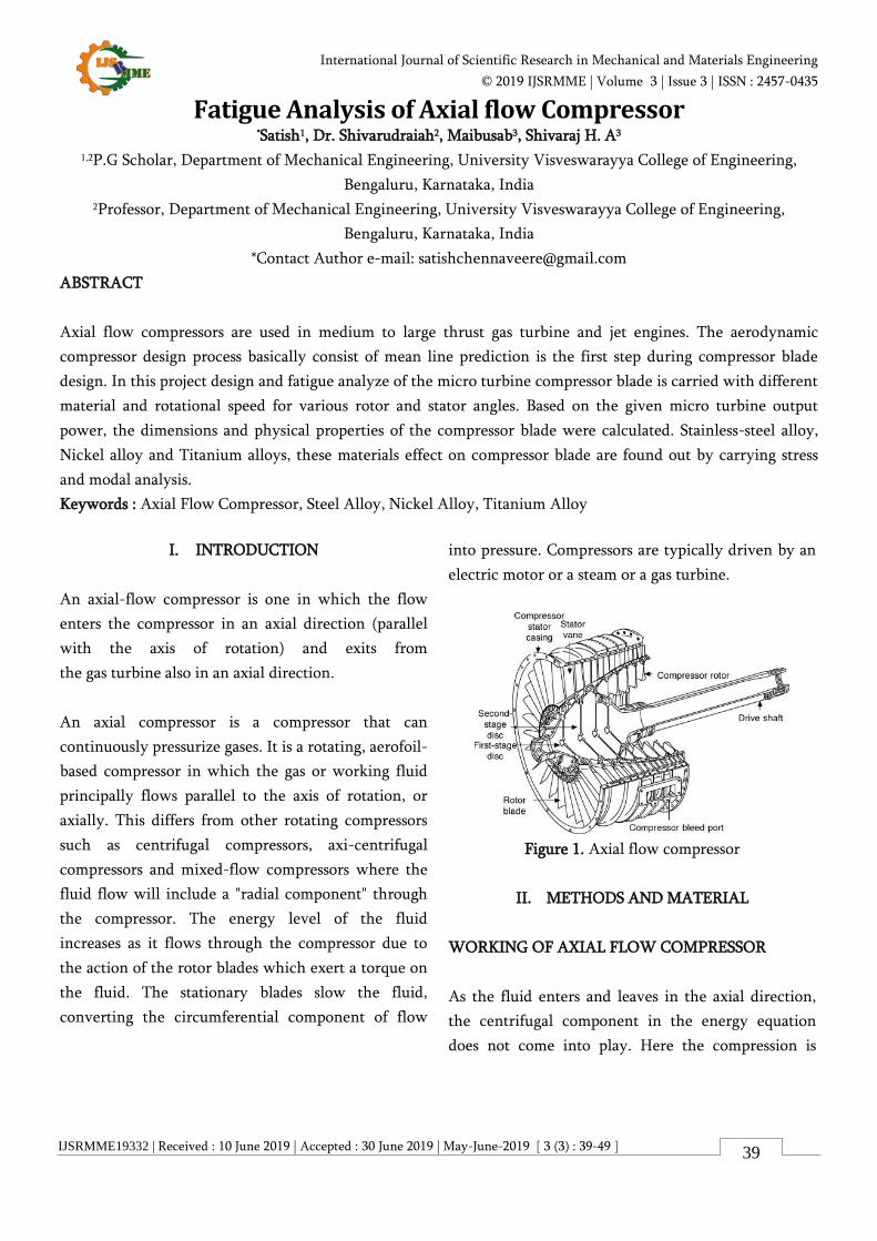
IJSRMME19332 | Received : 10 June 2019 | Accepted : 30 June 2019 | May-June-2019 [ 3 (3) : 39-49 ] International Journal of Scientific Research in Mechanical and Materials Engineering © 2019 IJSRMME | Volume 3 | Issue 3 | ISSN : 2457-0435 39 Fatigue Analysis of Axial flow Compressor * Satish 1 , Dr. Shivarudraiah 2 , Maibusab 3 , Shivaraj H. A 3 1,2 P.G Scholar, Department of Mechanical Engineering, University Visveswarayya College of Engineering, Bengaluru, Karnataka, India 2 Professor, Department of Mechanical Engineering, University Visveswarayya College of Engineering, Bengaluru, Karnataka, India *Contact Author e-mail: [email protected] ABSTRACT Axial flow compressors are used in medium to large thrust gas turbine and jet engines. The aerodynamic compressor design process basically consist of mean line prediction is the first step during compressor blade design. In this project design and fatigue analyze of the micro turbine compressor blade is carried with different material and rotational speed for various rotor and stator angles. Based on the given micro turbine output power, the dimensions and physical properties of the compressor blade were calculated. Stainless-steel alloy, Nickel alloy and Titanium alloys, these materials effect on compressor blade are found out by carrying stress and modal analysis. Keywords : Axial Flow Compressor, Steel Alloy, Nickel Alloy, Titanium Alloy I. INTRODUCTION An axial-flow compressor is one in which the flow enters the compressor in an axial direction (parallel with the axis of rotation) and exits from the gas turbine also in an axial direction. An axial compressor is a compressor that can continuously pressurize gases. It is a rotating, aerofoil- based compressor in which the gas or working fluid principally flows parallel to the axis of rotation, or axially. This differs from other rotating compressors such as centrifugal compressors, axi-centrifugal compressors and mixed-flow compressors where the fluid flow will include a "radial component" through the compressor. The energy level of the fluid increases as it flows through the compressor due to the action of the rotor blades which exert a torque on the fluid. The stationary blades slow the fluid, converting the circumferential component of flow into pressure. Compressors are typically driven by an electric motor or a steam or a gas turbine. Figure 1. Axial flow compressor II. METHODS AND MATERIAL WORKING OF AXIAL FLOW COMPRESSOR As the fluid enters and leaves in the axial direction, the centrifugal component in the energy equation does not come into play. Here the compression is
Transcript of Fatigue Analysis of Axial flow Compressor
IJSRMME19332 | Received : 10 June 2019 | Accepted : 30 June 2019 | May-June-2019 [ 3 (3) : 39-49 ]
International Journal of Scientific Research in Mechanical and Materials Engineering
© 2019 IJSRMME | Volume 3 | Issue 3 | ISSN : 2457-0435
39
Fatigue Analysis of Axial flow Compressor *Satish1, Dr. Shivarudraiah2, Maibusab3, Shivaraj H. A3
1,2P.G Scholar, Department of Mechanical Engineering, University Visveswarayya College of Engineering,
Bengaluru, Karnataka, India 2Professor, Department of Mechanical Engineering, University Visveswarayya College of Engineering,
Bengaluru, Karnataka, India
*Contact Author e-mail: [email protected]
ABSTRACT
Axial flow compressors are used in medium to large thrust gas turbine and jet engines. The aerodynamic
compressor design process basically consist of mean line prediction is the first step during compressor blade
design. In this project design and fatigue analyze of the micro turbine compressor blade is carried with different
material and rotational speed for various rotor and stator angles. Based on the given micro turbine output
power, the dimensions and physical properties of the compressor blade were calculated. Stainless-steel alloy,
Nickel alloy and Titanium alloys, these materials effect on compressor blade are found out by carrying stress
and modal analysis.
Keywords : Axial Flow Compressor, Steel Alloy, Nickel Alloy, Titanium Alloy
I. INTRODUCTION
An axial-flow compressor is one in which the flow
enters the compressor in an axial direction (parallel
with the axis of rotation) and exits from
the gas turbine also in an axial direction.
An axial compressor is a compressor that can
continuously pressurize gases. It is a rotating, aerofoil-
based compressor in which the gas or working fluid
principally flows parallel to the axis of rotation, or
axially. This differs from other rotating compressors
such as centrifugal compressors, axi-centrifugal
compressors and mixed-flow compressors where the
fluid flow will include a "radial component" through
the compressor. The energy level of the fluid
increases as it flows through the compressor due to
the action of the rotor blades which exert a torque on
the fluid. The stationary blades slow the fluid,
converting the circumferential component of flow
into pressure. Compressors are typically driven by an
electric motor or a steam or a gas turbine.
Figure 1. Axial flow compressor
II. METHODS AND MATERIAL
WORKING OF AXIAL FLOW COMPRESSOR
As the fluid enters and leaves in the axial direction,
the centrifugal component in the energy equation
does not come into play. Here the compression is
Volume 3 | Issue 3 | May-June-2019 | www.ijsrmme.com
Satish et al. Int. J. Sci. Res. Mech. Mater. Eng, May-June-2019, 3(3) : 39-49
40
fully based on diffusing action of the passages. The
diffusing action in stator converts absolute kinetic
head of the fluid into rise in pressure. The relative
kinetic head in the energy equation is a term that
exists only because of the rotation of the rotor. The
rotor reduces the relative kinetic head of the fluid and
adds it to the absolute kinetic head of the fluid i.e.,
the impact of the rotor on the fluid particles increases
its velocity (absolute) and thereby reduces the relative
velocity between the fluid and the rotor. In short, the
rotor increases the absolute velocity of the fluid and
the stator converts this into pressure rise. Designing
the rotor passage with a diffusing capability can
produce a pressure rise in addition to its normal
functioning. This produces greater pressure rise per
stage which constitutes a stator and a rotor together.
This is the reaction principle in turbomachines. If
50% of the pressure rise in a stage is obtained at the
rotor section, it is said to have a 50% reaction.
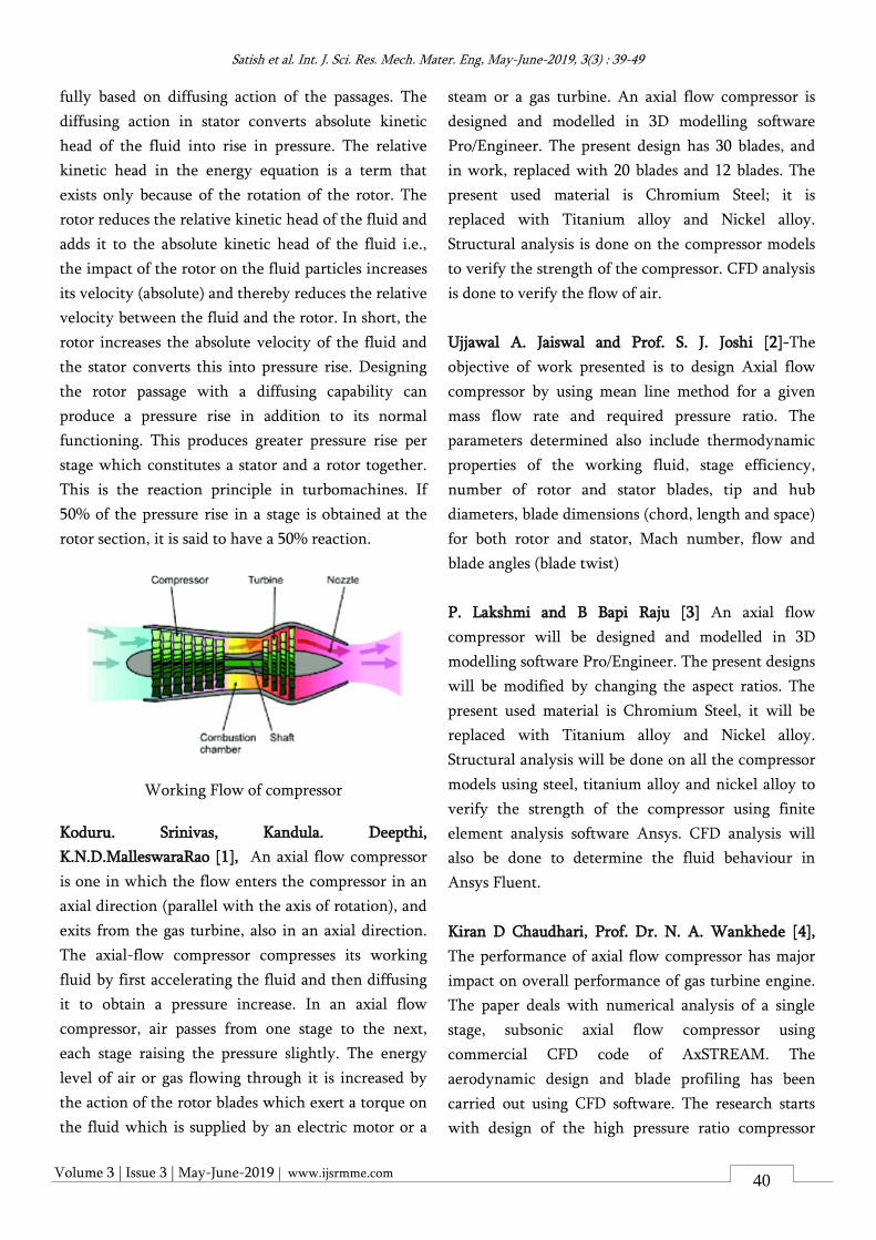
Working Flow of compressor
Koduru. Srinivas, Kandula. Deepthi,
K.N.D.MalleswaraRao [1], An axial flow compressor
is one in which the flow enters the compressor in an
axial direction (parallel with the axis of rotation), and
exits from the gas turbine, also in an axial direction.
The axial-flow compressor compresses its working
fluid by first accelerating the fluid and then diffusing
it to obtain a pressure increase. In an axial flow
compressor, air passes from one stage to the next,
each stage raising the pressure slightly. The energy
level of air or gas flowing through it is increased by
the action of the rotor blades which exert a torque on
the fluid which is supplied by an electric motor or a
steam or a gas turbine. An axial flow compressor is
designed and modelled in 3D modelling software
Pro/Engineer. The present design has 30 blades, and
in work, replaced with 20 blades and 12 blades. The
present used material is Chromium Steel; it is
replaced with Titanium alloy and Nickel alloy.
Structural analysis is done on the compressor models
to verify the strength of the compressor. CFD analysis
is done to verify the flow of air.
Ujjawal A. Jaiswal and Prof. S. J. Joshi [2]-The
objective of work presented is to design Axial flow
compressor by using mean line method for a given
mass flow rate and required pressure ratio. The
parameters determined also include thermodynamic
properties of the working fluid, stage efficiency,
number of rotor and stator blades, tip and hub
diameters, blade dimensions (chord, length and space)
for both rotor and stator, Mach number, flow and
blade angles (blade twist)
P. Lakshmi and B Bapi Raju [3] An axial flow
compressor will be designed and modelled in 3D
modelling software Pro/Engineer. The present designs
will be modified by changing the aspect ratios. The
present used material is Chromium Steel, it will be
replaced with Titanium alloy and Nickel alloy.
Structural analysis will be done on all the compressor
models using steel, titanium alloy and nickel alloy to
verify the strength of the compressor using finite
element analysis software Ansys. CFD analysis will
also be done to determine the fluid behaviour in
Ansys Fluent.
Kiran D Chaudhari, Prof. Dr. N. A. Wankhede [4],
The performance of axial flow compressor has major
impact on overall performance of gas turbine engine.
The paper deals with numerical analysis of a single
stage, subsonic axial flow compressor using
commercial CFD code of AxSTREAM. The
aerodynamic design and blade profiling has been
carried out using CFD software. The research starts
with design of the high pressure ratio compressor
Volume 3 | Issue 3 | May-June-2019 | www.ijsrmme.com
Satish et al. Int. J. Sci. Res. Mech. Mater. Eng, May-June-2019, 3(3) : 39-49
41
blade sections which yield a single stage pressure rise
up to 1.21, the constant tip diameter of the
compressor rotor blade for 15.5 kg/s, 14800 RPM,
276.5 KW power with a tip speed 167.7 m/s. Further
the design is optimized for minimum total pressure
loss. Analytical results compared with the numerical
analysis.
III. OBJECTIVE AND SCOPE
Objective
The objective of this study is to model a micro turbine
compressor blade and conduct stress analysis and
fatigue analysis based on its rotation per minute for
different stator and rotor angles.
Scope of work
The scope of study consists of following major parts
1. Problem study & input data finalization.
2. Design the dimension of the compressor based on
the given output power.
3. Mesh the model as per quality requirements.
4. Investigate the stress acting on the compressor
using structural analysis and Fatigue analysis of
the model for different rotational speed using the
finite element analysis program.
5. Project documentation with plots/sketches &
result study observation
6. ANSYS is the software used for analysis.
7. 3D model obtained from CATIA is imported to
ANSYS in STEP file format.
Geometrical Modelling
Compressor Materials
The material for the compressor blade is chosen into
three different materials.
Materials Items Paramete
r Value
Stainless
Steel
Modulus of
Elasticity E (GPa) 210
Density ρ (kgm3) 7850
Ultimate
Tensile
Strength
UTS
(MPa) 460
Yield
Strength σ (MPa) 250
Poisson Ratio N 0.3
Titanium
Alloy
Modulus of
Elasticity E (GPa) 96
Density ρ (kgm3) 7850
Ultimate
Tensile
Strength
UTS
(MPa) 1070
Yield
Strength σ (MPa) 930
Poisson Ratio N 0.36
Nickel
alloy
Modulus of
Elasticity E (GPa) 245
Density ρ (kgm3) 8650
Ultimate
Tensile
Strength
UTS
(MPa) 2300
Yield
Strength σ (MPa) 2100
Poisson Ratio N 0.325
ANALYSIS
Analysis has been carried out by using FEA software
ANSYS.
ANSYS Workbench 16 is the software used for
analysis. 3D model obtained from CATIA is imported
to ANSYS in STEP file format.
Volume 3 | Issue 3 | May-June-2019 | www.ijsrmme.com
Satish et al. Int. J. Sci. Res. Mech. Mater. Eng, May-June-2019, 3(3) : 39-49
42
Finite Element Method (FEM)
Finite Element Method (FEM) is also called as Finite
Element Analysis (FEA). Finite Element Method is a
basic analysis technique for resolving and substituting
complicated problems by simpler ones, obtaining
approximate solutions Finite element method being a
flexible tool is used in various industries to solve
several practical engineering problems. In finite
element method it is feasible to generate the relative
results.
ANSYS Software
ANSYS is an Engineering Simulation Software
(computer aided Engineering). Its tools cover Thermal,
Static, Dynamic, and Fatigue finite element analysis
along with other tools all designed to help with the
development of the product. The company was
founded in 1970 by Dr. John A. Swanson as Swanson
Analysis Systems, Inc. SASI. Its primary purpose was
to develop and market finite element analysis
software for structural physics that could simulate
static (stationary), dynamic (moving) and heat
transfer (thermal) problems. SASI developed its
business in parallel with the growth in computer
technology and engineering needs. The company
grew by 10 percent to 20 percent each year, and in
1994 it was sold. The new owners took SASI’s leading
software, called ANSYS, as their flagship product and
designated ANSYS, Inc. as the new company name.
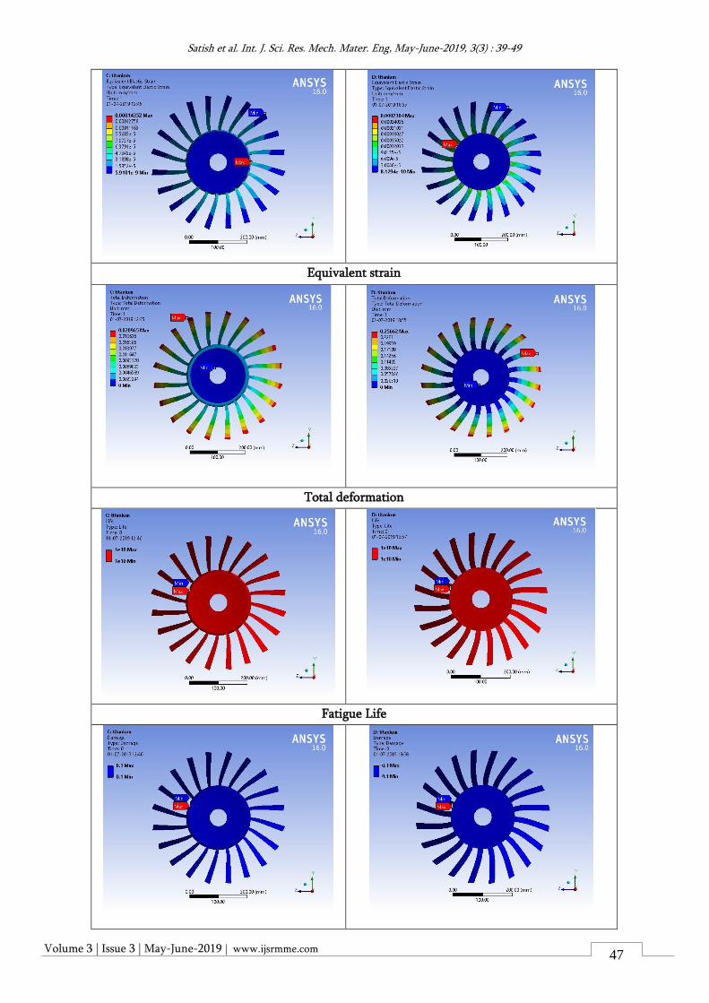
IV. RESULTS AND DISCUSSIONS
The results are analyzed for different angles of stator
and rotor with respect to materials.
1. Case 1: rotator angle 12.10 , stator angle 24.90
2. Case 2: rotator angle 26.40 , stator angle 29.00
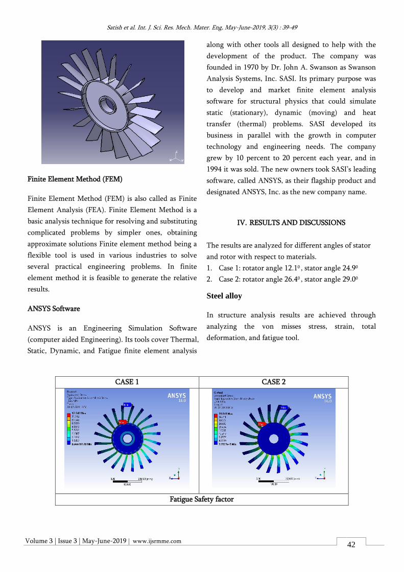
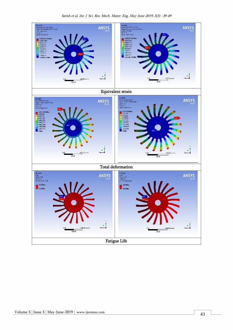
Steel alloy
In structure analysis results are achieved through
analyzing the von misses stress, strain, total
deformation, and fatigue tool.
CASE 1 CASE 2
Fatigue Safety factor
Volume 3 | Issue 3 | May-June-2019 | www.ijsrmme.com
Satish et al. Int. J. Sci. Res. Mech. Mater. Eng, May-June-2019, 3(3) : 39-49
43
Equivalent strain
Total deformation
Fatigue Life
Volume 3 | Issue 3 | May-June-2019 | www.ijsrmme.com
Satish et al. Int. J. Sci. Res. Mech. Mater. Eng, May-June-2019, 3(3) : 39-49
44
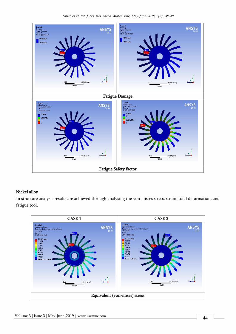
Fatigue Damage
Fatigue Safety factor
Nickel alloy
In structure analysis results are achieved through analysing the von misses stress, strain, total deformation, and
fatigue tool.
CASE 1 CASE 2
Equivalent (von-mises) stress
Volume 3 | Issue 3 | May-June-2019 | www.ijsrmme.com
Satish et al. Int. J. Sci. Res. Mech. Mater. Eng, May-June-2019, 3(3) : 39-49
45
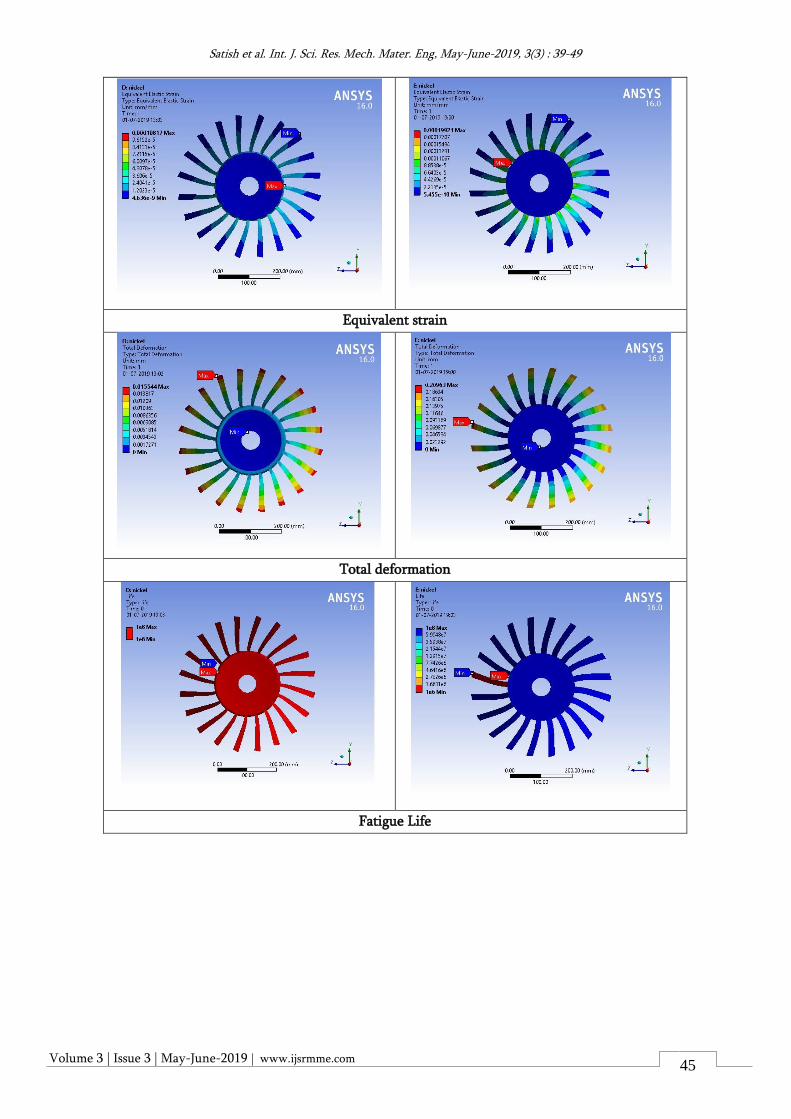
Equivalent strain
Total deformation
Fatigue Life
Volume 3 | Issue 3 | May-June-2019 | www.ijsrmme.com
Satish et al. Int. J. Sci. Res. Mech. Mater. Eng, May-June-2019, 3(3) : 39-49
46
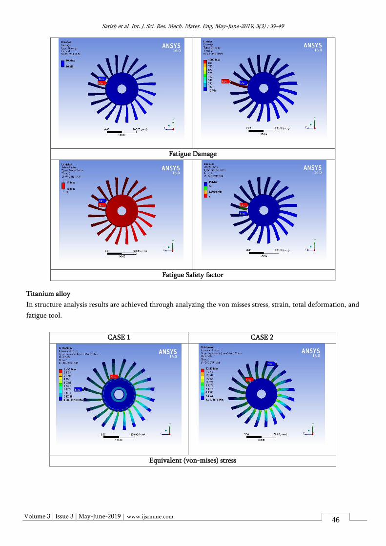
Fatigue Damage
Fatigue Safety factor
Titanium alloy
In structure analysis results are achieved through analyzing the von misses stress, strain, total deformation, and
fatigue tool.
CASE 1 CASE 2
Equivalent (von-mises) stress
Volume 3 | Issue 3 | May-June-2019 | www.ijsrmme.com
Satish et al. Int. J. Sci. Res. Mech. Mater. Eng, May-June-2019, 3(3) : 39-49
47
Equivalent strain
Total deformation
Fatigue Life
Volume 3 | Issue 3 | May-June-2019 | www.ijsrmme.com
Satish et al. Int. J. Sci. Res. Mech. Mater. Eng, May-June-2019, 3(3) : 39-49
48
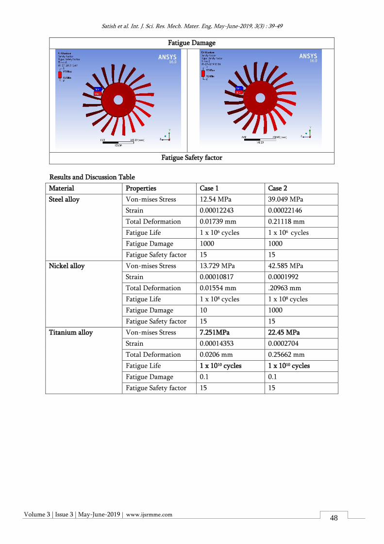
Fatigue Damage
Fatigue Safety factor
Results and Discussion Table
Material Properties Case 1 Case 2
Steel alloy Von-mises Stress 12.54 MPa 39.049 MPa
Strain 0.00012243 0.00022146
Total Deformation 0.01739 mm 0.21118 mm
Fatigue Life 1 x 10⁶ cycles 1 x 10⁶ cycles
Fatigue Damage 1000 1000
Fatigue Safety factor 15 15
Nickel alloy Von-mises Stress 13.729 MPa 42.585 MPa
Strain 0.00010817 0.0001992
Total Deformation 0.01554 mm .20963 mm
Fatigue Life 1 x 10⁸ cycles 1 x 10⁸ cycles
Fatigue Damage 10 1000
Fatigue Safety factor 15 15
Titanium alloy Von-mises Stress 7.251MPa 22.45 MPa
Strain 0.00014353 0.0002704
Total Deformation 0.0206 mm 0.25662 mm
Fatigue Life 1 x 10¹⁰ cycles 1 x 10¹⁰ cycles
Fatigue Damage 0.1 0.1
Fatigue Safety factor 15 15
Volume 3 | Issue 3 | May-June-2019 | www.ijsrmme.com
Satish et al. Int. J. Sci. Res. Mech. Mater. Eng, May-June-2019, 3(3) : 39-49
49
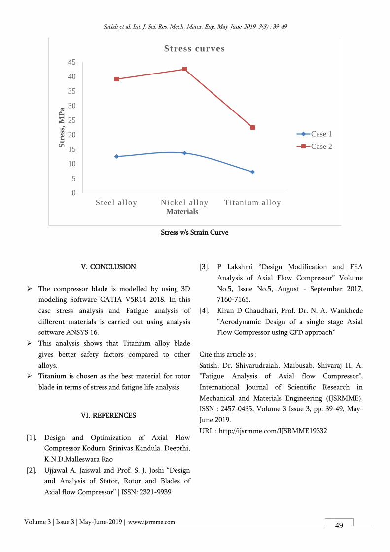
Stress v/s Strain Curve
V. CONCLUSION
➢ The compressor blade is modelled by using 3D
modeling Software CATIA V5R14 2018. In this
case stress analysis and Fatigue analysis of
different materials is carried out using analysis
software ANSYS 16.
➢ This analysis shows that Titanium alloy blade
gives better safety factors compared to other
alloys.
➢ Titanium is chosen as the best material for rotor
blade in terms of stress and fatigue life analysis
VI. REFERENCES
[1]. Design and Optimization of Axial Flow
Compressor Koduru. Srinivas Kandula. Deepthi,
K.N.D.Malleswara Rao
[2]. Ujjawal A. Jaiswal and Prof. S. J. Joshi “Design
and Analysis of Stator, Rotor and Blades of
Axial flow Compressor” | ISSN: 2321-9939
[3]. P Lakshmi “Design Modification and FEA
Analysis of Axial Flow Compressor” Volume
No.5, Issue No.5, August - September 2017,
7160-7165.
[4]. Kiran D Chaudhari, Prof. Dr. N. A. Wankhede
“Aerodynamic Design of a single stage Axial
Flow Compressor using CFD approach”
Cite this article as :
Satish, Dr. Shivarudraiah, Maibusab, Shivaraj H. A,
"Fatigue Analysis of Axial flow Compressor",
International Journal of Scientific Research in
Mechanical and Materials Engineering (IJSRMME),
ISSN : 2457-0435, Volume 3 Issue 3, pp. 39-49, May-
June 2019.
URL : http://ijsrmme.com/IJSRMME19332
0
5
10
15
20
25
30
35
40
45
Steel al loy Nickel al loy Titanium al loy
Str
ess,
MP
a
Materials
Stress curves
Case 1
Case 2


![AXIAL FATIGUE PROPERTIES OF LEAN Fe-Mo-Ni ALLOYS › ... › axial-fatigue-properties-of-lean-fe-mo-ni-alloys.pdftherefore beneficial to fatigue performance [7] [8]. It is also known](https://static.fdocuments.in/doc/165x107/5f0e5d3e7e708231d43ee330/axial-fatigue-properties-of-lean-fe-mo-ni-alloys-a-a-axial-fatigue-properties-of-lean-fe-mo-ni-.jpg)