Simulation and Optimization of an Axial Compressor...
32
THESIS FOR THE DEGREE OF LICENTIATE OF ENGINEERING IN THERMO AND FLUID DYNAMICS Simulation and Optimization of an Axial Compressor Considering Tip Clearance Flow MARCUS LEJON Department of Applied Mechanics Division of Fluid Dynamics CHALMERS UNIVERSITY OF TECHNOLOGY Gothenburg, Sweden 2016
Transcript of Simulation and Optimization of an Axial Compressor...

THESIS FOR THE DEGREE OF LICENTIATE OF ENGINEERING IN THERMOAND FLUID DYNAMICS
Simulation and Optimization of an Axial CompressorConsidering Tip Clearance Flow
MARCUS LEJON
Department of Applied MechanicsDivision of Fluid Dynamics
CHALMERS UNIVERSITY OF TECHNOLOGY
Gothenburg, Sweden 2016

Simulation and Optimization of an Axial Compressor Considering Tip Clearance FlowMARCUS LEJON
c© MARCUS LEJON, 2016
Thesis for the degree of Licentiate of Engineering 2016:06ISSN 1652-8565Department of Applied MechanicsDivision of Fluid DynamicsChalmers University of TechnologySE-412 96 GothenburgSwedenTelephone: +46 (0)31-772 1000
Chalmers ReproserviceGothenburg, Sweden 2016

Simulation and Optimization of an Axial Compressor Considering Tip Clearance FlowThesis for the degree of Licentiate of Engineering in Thermo and Fluid DynamicsMARCUS LEJONDepartment of Applied MechanicsDivision of Fluid DynamicsChalmers University of Technology
Abstract
With ever-increasing demands for high efficiency in axial compressors, it has becomeimportant to consider more geometrical features of the manufactured component in thedesign phase. Many possibilities open if the level of fidelity of the computational model canbe increased. A higher level of detail leads to enhanced performance of components, as theneed to be conservative in the design phase is reduced. Better performance is important forreducing fuel consumption and the weight of the component and, consequently, decreasingthe environmental impact.
An axial compressor consists of rotating and stationary blade rows, where a distancebetween the rotating blades and the inner casing (shroud) is called the tip gap or tipclearance and is required to avoid contact of the blades with the shroud during engineoperation. Large tip gaps in relation to the blade height can typically be found in therear stages of transonic compressors. If the size of the tip gap is large in relation to theblade height, it can affect the flow in the rotor passage significantly. Including a tip gapin the optimization process of a compressor stage can therefore be of importance even inthe early design phase to find geometries that will reach the design point at the designrotational speed.
In this thesis, different turbulence models and wall modeling approaches are used tocalculate the flow in a transonic compressor stage with a large tip clearance. The benefitsof including the tip clearance in the optimization process of a transonic compressor areshown and discussed. It is shown that considering the tip clearance in the optimizationprocess is important to be able to reach the specified design point. Furthermore, fromthe optimization results it is shown that redistribution of the flow as a result of blockagein the tip region impacts the design variables over the entire span.
Keywords: compressor, design, CFD, tip clearance, turbulence models, validation, opti-mization
i

ii

List of publications
This thesis is based on the work contained in the following publications:
I M. Lejon, L-E. Eriksson, N. Andersson and L. Ellbrant, 2015, Simulation of Tip-Clearance Effects in a Transonic Compressor, Proceedings of ASME Turbo Expo2015, June 15–19, Montreal, Canada
II M. Lejon, N. Andersson, L. Ellbrant and H. Martensson, 2015, CFD Optimizationof a Transonic Compressor Stage with a Large Tip Gap, 22nd ISABE Conference,October 25–30, Phoenix, USA
iii

iv

Acknowledgements
First, I would like to thank my supervisors at Chalmers, Niklas Andersson and Lars-ErikEriksson, for supporting me in this undertaking and always taking the time to discuss myquestions and concerns.
I would also like to thank Hans Martensson, Lars Ellbrant and Pieter Groth at GKNAerospace for all their feedback and insight in compressor aerodynamics that they haveprovided. Hans Martensson has provided great support and has shared part of his vastknowledge on different considerations related to compressor design.
Thanks go to my colleagues and friends at Chalmers and GKN Aerospace who giveme with an excellent working environment. Special thanks go to Alexandre CapitaoPatrao at Chalmers for being a good friend and roomie, with whom I’ve had manystimulating discussions on aircraft wings, propellers and matters completely unrelated towork. Thanks go to Gustav Johansson at GKN for always being cheerful and trying toget me to exercise more in terms of playing floorball.
I would like to thank my family for always supporting me. Finally, I would like tothank my wonderful girlfriend Linda for being there.
This work was funded by the Swedish National Aviation Engineering Research Programme,NFFP. The author would like to acknowledge the financial support of VINNOVA, theSwedish Defence Material Administration (FMV) and GKN Aerospace. The authorwould also like to thank the National Supercomputer Center, Linkoping, Sweden, andChalmers Centre for Computational Science and Engineering, Gothenburg, Sweden, forthe computational resources required for this work.
v

vi

The noblest pleasure is the joy of understanding- Leonardo da Vinci
vii

viii
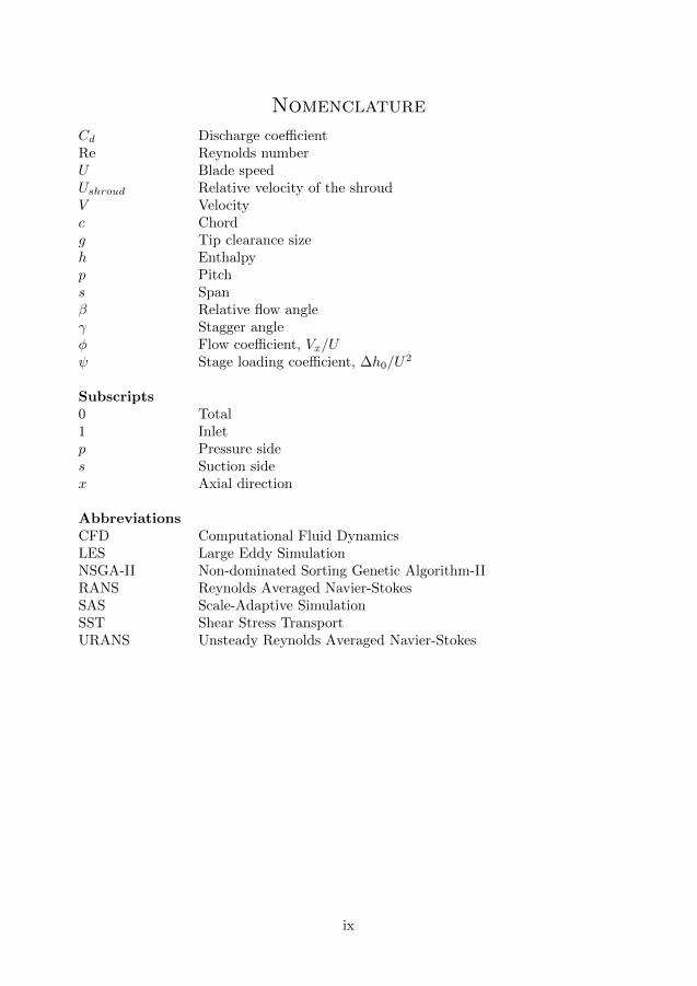
Nomenclature
Cd Discharge coefficientRe Reynolds numberU Blade speedUshroud Relative velocity of the shroudV Velocityc Chordg Tip clearance sizeh Enthalpyp Pitchs Spanβ Relative flow angleγ Stagger angleφ Flow coefficient, Vx/Uψ Stage loading coefficient, ∆h0/U
2
Subscripts0 Total1 Inletp Pressure sides Suction sidex Axial direction
AbbreviationsCFD Computational Fluid DynamicsLES Large Eddy SimulationNSGA-II Non-dominated Sorting Genetic Algorithm-IIRANS Reynolds Averaged Navier-StokesSAS Scale-Adaptive SimulationSST Shear Stress TransportURANS Unsteady Reynolds Averaged Navier-Stokes
ix

x

Contents
Abstract i
List of publications iii
Acknowledgements v
Nomenclature ix
Contents xi
1 Introduction 11.1 Problem definition . . . . . . . . . . . . . . . . . . . . . . . . . . . . . . . . . 11.2 Scope of work . . . . . . . . . . . . . . . . . . . . . . . . . . . . . . . . . . . . 2
2 Optimization approach 3
3 Tip clearance flow 43.1 Impact on stability margin . . . . . . . . . . . . . . . . . . . . . . . . . . . . 43.2 Tip clearance modeling . . . . . . . . . . . . . . . . . . . . . . . . . . . . . . 63.3 Turbulence models . . . . . . . . . . . . . . . . . . . . . . . . . . . . . . . . . 73.4 Wall modeling approach . . . . . . . . . . . . . . . . . . . . . . . . . . . . . . 83.5 Tip clearance loss . . . . . . . . . . . . . . . . . . . . . . . . . . . . . . . . . . 9
4 Concluding remarks 114.1 Meshing . . . . . . . . . . . . . . . . . . . . . . . . . . . . . . . . . . . . . . . 114.2 Turbulence model and wall treatment . . . . . . . . . . . . . . . . . . . . . . 114.3 Design . . . . . . . . . . . . . . . . . . . . . . . . . . . . . . . . . . . . . . . . 12
5 Future work 13
6 Summary of Papers 146.1 Paper I . . . . . . . . . . . . . . . . . . . . . . . . . . . . . . . . . . . . . . . 146.1.1 Division of work . . . . . . . . . . . . . . . . . . . . . . . . . . . . . . . . . 146.1.2 Summary and discussion . . . . . . . . . . . . . . . . . . . . . . . . . . . . 146.2 Paper II . . . . . . . . . . . . . . . . . . . . . . . . . . . . . . . . . . . . . . . 146.2.1 Division of work . . . . . . . . . . . . . . . . . . . . . . . . . . . . . . . . . 146.2.2 Summary and discussion . . . . . . . . . . . . . . . . . . . . . . . . . . . . 15
xi

xii

1 Introduction
The axial compressor is an essential part of a modern aircraft engine and is made up of anumber of rotating and stationary blade rows. Work is done on the air by the compressorbefore it enters the combustion chamber, and a number of considerations, aerodynamicand structural, need to be taken into account in the design phase of the component.
An axial compressor consists of rotating and stationary blade rows, where a distancebetween the rotating blades and the inner casing (shroud) is called the tip gap or tipclearance and is required to avoid contact of the blades with the shroud during engineoperation. Thermal expansion of the rotating blades and elongation of blades due tocentrifugal forces are factors that need to be taken into account when setting the tipclearance for a blade row. Furthermore, g-forces e.g. during landing can momentarilyalter the tip clearance in an aircraft engine.
At the tip of an aircraft wing, the pressure difference on the pressure and suctionsides gives rise to a tip vortex. Similarly, the pressure difference of the pressure andsuction surfaces of a compressor rotor near the tip gives rise to an air flow through thetip clearance. In an axial compressor, the proximity of the shroud and flow from nearbyblade passages adds another dimension to the complexity of the flow in this region.
The tip clearance can have a large effect on performance. As it increases in size, itsinfluence ranges from negligible (for a very small tip clearance) to substantial, where it hasa considerable adverse effect on efficiency and on the stable operating range of the entireturbo machine. Although the tip clearance size is usually on the order of millimeters orparts of a millimeter, it can be responsible for a large part of the total losses [1].
1.1 Problem definition
Accurately predicting the effects of tip clearance flow on performance poses a greatchallenge for the axial compressor engineer. At the same time it cannot be neglected if itis suspected to have a large impact.
A number of decisions must be made when doing Computational Fluid Dynamics(CFD) calculations of an axial compressor stage. The first question with respect to thetip clearance is whether the clearance should be included in the simulation model at all.If it is included, different degrees of simplification can be made to the computationaldomain in order to simplify the grid generation process, possibly at the expense of someimportant flow physics. When the computational domain has been generated, a numberof important choices remain. Should a steady or time dependant solution be computed?Which turbulence model should be used? How should the boundary layers be resolved?
The multitude of aspects to consider makes it difficult to give a clear answer as towhat choices to make, and the choices will depend largely on available computationalresources, available time and the purpose of the calculations. The present thesis aims togive a foundation on which to base such decisions, including an analysis of how the designof an axial compressor stage can be influenced by taking the tip clearance into account.
1

1.2 Scope of work
The main focus of this thesis is on modeling of tip clearance flow and its impact oncompressor design. Tip clearance flow and its impact on compressor performance isdiscussed, giving the reader an introduction to the work that has been published in thefield.
2
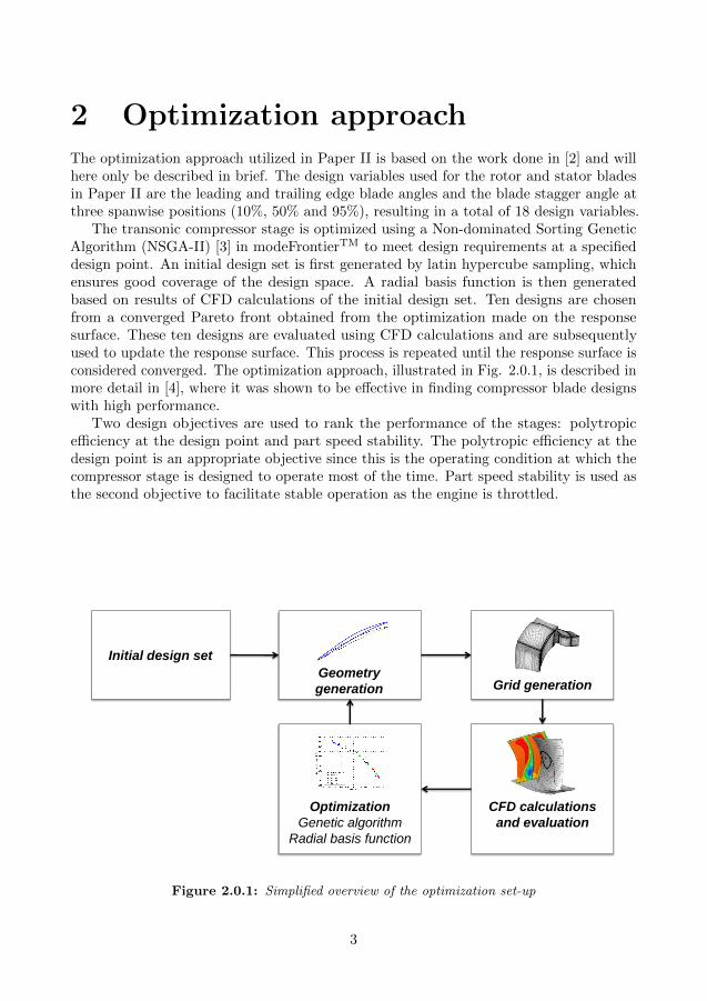
2 Optimization approachThe optimization approach utilized in Paper II is based on the work done in [2] and willhere only be described in brief. The design variables used for the rotor and stator bladesin Paper II are the leading and trailing edge blade angles and the blade stagger angle atthree spanwise positions (10%, 50% and 95%), resulting in a total of 18 design variables.
The transonic compressor stage is optimized using a Non-dominated Sorting GeneticAlgorithm (NSGA-II) [3] in modeFrontierTM to meet design requirements at a specifieddesign point. An initial design set is first generated by latin hypercube sampling, whichensures good coverage of the design space. A radial basis function is then generatedbased on results of CFD calculations of the initial design set. Ten designs are chosenfrom a converged Pareto front obtained from the optimization made on the responsesurface. These ten designs are evaluated using CFD calculations and are subsequentlyused to update the response surface. This process is repeated until the response surface isconsidered converged. The optimization approach, illustrated in Fig. 2.0.1, is described inmore detail in [4], where it was shown to be effective in finding compressor blade designswith high performance.
Two design objectives are used to rank the performance of the stages: polytropicefficiency at the design point and part speed stability. The polytropic efficiency at thedesign point is an appropriate objective since this is the operating condition at which thecompressor stage is designed to operate most of the time. Part speed stability is used asthe second objective to facilitate stable operation as the engine is throttled.
Geometry
generation Grid generation
CFD calculations
and evaluation
Optimization
Genetic algorithm
Radial basis function
Initial design set
Figure 2.0.1: Simplified overview of the optimization set-up
3

3 Tip clearance flowTip clearance flow, illustrated in Fig. 3.0.1, is mainly driven by the pressure differencebwtween the pressure and suction sides of the blade at the tip [5]. This means thataerodynamic loading has a large impact on the strength of the tip clearance flow. It isstated in [1] that the average pressure along the chord on the suction side of the rotor bladeat the tip is almost independent of the tip clearance size. Separation and re-attachmentof the flow can occur in the tip clearance as discussed in [6], which has an effect on themass flow through the clearance [7]. Part of the flow that passes through the clearancerolls up to a vortex, referred to as the tip clearance vortex. An example of a tip clearancevortex trajectory in a blade-to-blade view is illustrated in Fig. 3.0.2.
For very small tip clearances, the main contribution to losses associated with the tipclearance is caused by viscous losses generated at the shroud. As the clearance increasesin size, losses due to mixing of the tip clearance flow become dominant [8]. It wasshown experimentally in [9] that a small tip clearance can have a beneficial impact onperformance compared to a sealed tip, and it was shown in [8, 9] that an optimal tipclearance size can exist. In [8], the existence of an optimal tip clearance is explained interms of the competing loss mechanisms, viscous and mixing losses for small and largetip clearances, respectively. For some clearance, the sum of these two loss sources is at aminimum (in the range 0.1–1% of the blade height for the compressors discussed in [8]).
3.1 Impact on stability margin
An increase in tip clearance size can significantly reduce the stability margin of a compressorstage, as shown e.g. in [10]. The topic of stall associated with tip clearance flow is discussedin numerous papers, e.g. for a subsonic compressor in [11] and for a transonic compressorin [12].
The onset of stall in a transonic compressor was investigated in [12] using Large EddySimulations (LES) and experimental measurements. The stall process for the investigated
Pressureside
Suctionside
ωR
r
θx
ROTORBLADE
SHROUD
Figure 3.0.1: Tip clearance flow illustration in a relative frame of reference
4

UV∞
Figure 3.0.2: Example of a tip clearance vortex trajectory shown as a dashed line
compressor is well described and will here be summarized.Random oscillation of the tip clearance vortex and its interaction with the passage
shock is described in [12] to be the main trigger for the occurrence of a rotating stall cell.The onset of the rotating stall cell is explained by the formation of a stall cell downstreamof the sonic plane in the tip region, where the region of low momentum influences theadjacent passage. The route from a near stall operating condition to the formation of arotating stall cell is described as a step-by-step process based on LES calculation results.
1. The passage shock fully detach.
2. The tip clearance vortex trajectory moves forward to the leading edge. Reversal oftip clearance flow occurs at the trailing edge, impinging on the pressure side of theadjacent rotor blade.
3. Tip clearance flow spill over the leading edge of the adjacent blade.
The effect of tip clearance flow is not only local, as described above, but can affect theflow far away from the tip region as shown in [9] and in Paper II. In [9], a change of thetip clearance size affected a separation at the hub, effectively increasing the stall marginof the rotor. A large separation at an end-wall, such as the rotor hub, can occur whenthe flow is diffused to a level at which separation occurs, similar to separation caused bya high level of diffusion in a duct. If the tip clearance increases in size, a larger region oflow momentum fluid at the tip will limit the overall passage diffusion, thereby reducingthe separation in regions away from the tip.
5

3.2 Tip clearance modeling
The tip clearance of a compressor rotor is typically modeled in one of three ways. Thetip clearance can be set as a periodic boundary, it can be gridded using a ”pinch-tip”approach, or it can be gridded using a multi-block approach.
By applying a periodic boundary condition over the blade tip, see Fig. 3.2.1a, thetip clearance is not resolved but still allows for a mass flow from the suction side to thepressure side. Viscous losses and mixing effects over the blade tip are neglected. Flowseparation in the tip clearance, which in reality would cause blockage if the tip has afinite thickness, can be accounted for by reducing the size of the tip clearance. However,since the flow sees the blade tip with a periodic boundary as a sharp edge, there will be acontraction of the flow [7]. The relation between the size of the modeled tip clearanceand the actual geometrical tip clearance must be evaluated on a case-to-case basis. Theperiodic boundary condition approach was used for compressors in e.g. [13–15] and for atwo-stage turbine already in 1990 in [16].
(A) (B) (C)
Blade Blade Blade
Shroud Shroud Shroud
Periodic
boundary
condition
(a) Periodic boundary(A) (B) (C)
Blade Blade Blade
Shroud Shroud Shroud
Periodic
boundary
condition
(b) Pinch-tip model(A) (B) (C)
Blade Blade Blade
Shroud Shroud Shroud
Periodic
boundary
condition
(c) Multi-block approach
Figure 3.2.1: Tip clearance modeling approaches
The pinch-tip approach requires a zero blade thickness at the tip. In order to achievethis, the blade tip corners can be rounded or the tip geometry can be changed to a wedgeshape to extend the computational grid into the tip clearance as shown in Fig. 3.2.1b.This is done to avoid adding complexity, but often at the expense of quality, to thecomputational grid. The pinch-tip approach was used e.g. in [15, 17–19]. Similar issuesas for the periodic boundary can be seen, which are discussed in [7].
The multi-block approach where the tip clearance is fully resolved with a separategrid block has become more and more common as the level of fidelity of simulationshas increased. The approach is illustrated in Fig. 3.2.1c. A reason why the multi-blockapproach is attractive is that it requires no modification of the blade geometry. Themulti-block approach was used e.g. in [20–22].
The study presented in [6] compared the three approaches described above for a lowspeed compressor. The tip clearance size was reduced for the pinch-tip and periodic
6

boundary condition approaches since flow separation was suspected to occur along theblade tip. The pinch-tip model overpredicted the total losses, while using the periodicboundary condition in the tip clearance resulted in an underprediction. The best overallagreement with experimental data was obtained using the multi-block approach.
The multi-block approach was compared with a periodic boundary condition over thetip clearance in [23] for the transonic compressor rotor NASA Rotor 37, which has a tipclearance of 0.45% of the blade height. It was discussed that expansion occurs over thetip clearance. Consequently, the effect of separation on vena contracta was not consideredwhen the periodic boundary condition was used. In general, results presented in the studyfor a periodic boundary condition were in good agreement with results obtained with themulti-block approach.
The number of grid points in the radial direction in the tip clearance region variesconsiderably in the literature depending on the computational power at the time, thetip clearance size, the tip clearance modeling approach and the wall modeling approach.A periodic boundary condition and 2 grid nodes were used in [13] and [14], while themulti-block approach, which compared well with experimental data, resolved a 1% tipclearance size to blade height using 31 grid nodes in [22].
3.3 Turbulence models
The predicted performance of an axial compressor stage was shown to be largely affectedby the choice of the turbulence model in Paper I.
NASA Rotor 37 was investigated in [17] with steady state calculations using the k-ε andk-ω turbulence models, and with unsteady calculations using the k-ε turbulence model. Thetip clearance was modeled with a pinch-tip approach (see Section 3.2), and wall functionswere used for all calculations. The best agreement to one-dimensional experimentaldata was found for unsteady calculations using the k-ε turbulence model. Comparingthe steady state results, it was found that the k-ε turbulence model underpredicted thetotal pressure ratio and total temperature ratio, and slightly overpredicted the adiabaticefficiency. The k-ω turbulence model showed an overprediction of the total pressure ratio,total temperature ratio and the adiabatic efficiency.
Simulations were made of a half-scale six stage axial compressor in [22] with tipclearances around 1% of the blade span. The tip gap was resolved using a multi-blockapproach, and a y+ value of around 1 was used for the finest mesh. The k-ε and thek-ω Menter Shear-Stress Transport (SST) turbulence models were compared in the study.Furthermore, RANS and URANS simulation results obtained using the k-ω Menter SSTturbulence model were compared with experimental results. It was discussed that thek-ε turbulence model generally overpredicts the stall margin, while the k-ω Menter SSTmodel generally underpredicts it. It was also discussed and shown that the drawbackof the k-ω Menter SST turbulence model in terms of underpredicting the stall margincould be alleviated by using the re-attachment model of Menter [24]. Furthermore, it wasshown that the performance at the design point was relatively insensitive to the choice ofturbulence model, grid size and whether or not the simulation was done as steady state orunsteady. The choice became more important near stall, where the slope of the speedline
7

for the unsteady simulation was closer to the experiment.
3.4 Wall modeling approach
The choice of how to resolve the boundary layer was shown in Paper I to play an importantpart in the performance prediction of an axial compressor stage. Two approaches wereanalyzed: the k-ε turbulence model using wall functions and the k-ε turbulence modelusing Chien’s low-Reynolds formulation, where the first grid node away from the wallis placed in the viscous sub-layer to accurately resolve the boundary layer. Using wallfunctions was shown to predict a thicker boundary layer compared to the low-Reynoldsformulation. A thicker boundary layer decreases the turning over the rotor (increase thedeviation angle), which reduces the work done by the blade on the fluid. Performanceparameters such as total pressure ratio and polytropic efficiency predicted using thelow-Reynolds model show a closer agreement to the experimental measurements in PaperI compared to wall functions.
8

3.5 Tip clearance loss
Expressions for the change in efficiency caused by viscous shear at the shroud and mixingloss (using Denton’s leakage mixing model [25]) are shown in [8], here reproduced here asEq. 3.5.1 and Eq. 3.5.2.
∆ηshear ∼ Re−1(gs
)−1( cs
)2(Ushroud
V1
)2 φ2
ψ cos3 β1(3.5.1)
∆ηmixing ∼ Cd
( cp
)(gs
)(1 − Vp
Vs
)√1 −
(VpVs
)2φ2
ψ cos3 β1(3.5.2)
Where Re is the Reynolds number, g/s is the ratio of the tip clearance size to thespan, c/s is the chord to span ratio, c/p is the chord to pitch ratio, Ushroud is the relativevelocity of the shroud, V1 is the inlet velocity, β1 is the inlet relative flow angle, φ is theflow coefficient, ψ is the stage loading coefficient and Cd is a discharge coefficient. Vp/Vsis the ratio of the velocity on the pressure side to the velocity on the suction side, whichis approximated in [8] as
VpVs
≈√
1 − 2ψ
φ
( cp
)−1 cos2 β1cos γ
(3.5.3)
where γ is the stagger angle. Good agreement between the computed level of loss withthe loss calculated using Eq. 3.5.2 was found for tip clearance sizes up to 3.4% of theblade height [8]. A number of observations can be made from these expressions in termson the dependence of the tip clearance loss on other variables. To decrease the efficiencyloss due to shear stress, it would be benefitial with low values for the Reynolds number,c/s, Ushroud, β1 and φ, and high values for g/s, ψ and V1. To decrease the efficiency lossdue to mixing it would be beneficial to have low values for g/s, γ, ψ and φ, and highvalues for c/p and β1. An example of the effect of varying ψ, β1, φ and c/p one at a time(to visualize the trend) on the mixing loss is shown in Fig. 3.5.1. By decreasing the stageloading coefficient, ψ, the mass flow through the clearance would decrease and the mixinglosses would be lower.
9

0.8 0.9 1 1.1 1.20.8
0.85
0.9
0.95
1
η mix
ing [%
]
Normalized variable value [−]
c/pφψβ
1
Figure 3.5.1: Effect of indidvidual variables on mixing loss
10

4 Concluding remarksThe following subsections present conclusions and lessons learned by the author, in partfrom the literature study, but mainly from the work presented in Paper I and Paper II.
4.1 Meshing
• The tip clearance should be resolved with a separate grid block to accurately representthe geometry, to facilitate good grid quality and to avoid making assumptions aboutflow features in the clearance. As discussed in Section 3.2, using a pinch-tip approachor a periodic boundary condition at the tip can require artificially changing the sizeof the tip clearance to match experimental data in terms of mass flow through theclearance.
• If wall functions are used, it can be a good rule-of-thumb to use evenly spaced gridpoints in the radial direction in the tip clearance region. Placing the first nodeaway from the shroud and the blade tip at a distance suitable for wall functionsdetermines the radial grid spacing in the clearance.
4.2 Turbulence model and wall treatment
• The k-ε turbulence model with wall functions was shown to give overall goodagreement with experimental data in Paper I. The overall underprediction of thestage performance compared to experimental results indicates that this approachmay give a conservative performance estimate. The relatively low computationaltime needed, compared to Chien’s low-Reynolds model evaluated in the study, makesit suitable to use in an optimization set-up. Ranking of designs in terms of efficiencywas evaluated in Paper II using wall functions and the low-Reynolds model, where itwas shown that the same ranking was predicted by both wall modeling approaches.
• For detailed studies at an operating point away from stall, e.g. at the design point,it can be suitable to use the k-ε turbulence model with a low-Reynolds model toresolve the boundary layers (Chien’s low-Reynolds formulation of the k-ε turbulencemodel was compared with wall functions and experimental data in Paper I).
• Considering the ability to predict performance near stall in [22], it can be suitableto evaluate the capability of the k-ω Menter SST turbulence model with the re-attachment model of Menter [24] to predict near stall performance for other axialcompressors and other tip clearance sizes.
• The author of the present thesis has found an improved stall margin predictionwhen making unsteady calculations, e.g. the SAS-SST simulation in Paper I, whichwas closest to the experimental stall line. Unsteady calculations were recommendedin [22] to accurately predict the slope of the speedline near stall.
11

4.3 Design
• If including the tip clearance has a large effect on the results from CFD calculations,then it can be appropriate to include the tip clearance in the optimization process.As discussed in Paper II, the tip clearance flow gives rise to blockage in the tipregion causing a redistribution of the flow in the blade passage. Redistribution offlow in the blade passage was in turn shown to affect the design variables over theentire blade span.
12

5 Future workOngoing work includes evaluation of the impact of manufacturing imperfections anddeviations on a blade design. Since certain tolerances are used in manufacturing, theblades are never perfectly smooth and geometrical variations can be present that couldadversely affect the performance. Furthermore, wear and tear during engine operationwill increase the level of surface roughness over time. Investigating blade designs that arerobust to manufacturing and in-service variations would be an interesting topic of highrelevance for industry applications. Furthermore, work is currently being done on thestability criteria used to rank compressor stages in the optimization process.
The tip clearance is an important aspect to consider in the design of an axial compressorstage, and it would be interesting to further investigate means of reducing its influenceon performance. A shrouded rotor blade could have a beneficial impact, and the topicwould make an interesting research project. An interesting topic would also be to assessthe capability of different turbulence models to predict the onset of stall for a transoniccompressor stage configuration with a large tip gap, comparing predictions with detailedmeasurement data.
13
6 Summary of Papers
6.1 Paper I
M. Lejon, L-E. Eriksson, N. Andersson and L. Ellbrant, 2015, Simulation of Tip-ClearanceEffects in a Transonic Compressor, Proceedings of ASME Turbo Expo 2015, June 15–19,Montreal, Canada
6.1.1 Division of work
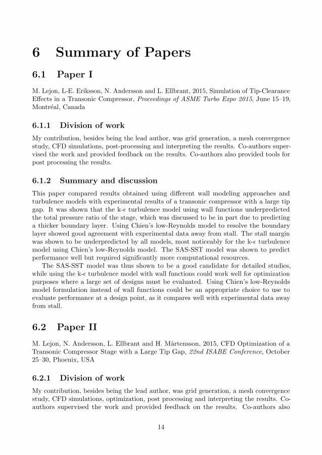
My contribution, besides being the lead author, was grid generation, a mesh convergencestudy, CFD simulations, post-processing and interpreting the results. Co-authors super-vised the work and provided feedback on the results. Co-authors also provided tools forpost processing the results.
6.1.2 Summary and discussion
This paper compared results obtained using different wall modeling approaches andturbulence models with experimental results of a transonic compressor with a large tipgap. It was shown that the k-ε turbulence model using wall functions underpredictedthe total pressure ratio of the stage, which was discussed to be in part due to predictinga thicker boundary layer. Using Chien’s low-Reynolds model to resolve the boundarylayer showed good agreement with experimental data away from stall. The stall marginwas shown to be underpredicted by all models, most noticeably for the k-ε turbulencemodel using Chien’s low-Reynolds model. The SAS-SST model was shown to predictperformance well but required significantly more computational resources.
The SAS-SST model was thus shown to be a good candidate for detailed studies,while using the k-ε turbulence model with wall functions could work well for optimizationpurposes where a large set of designs must be evaluated. Using Chien’s low-Reynoldsmodel formulation instead of wall functions could be an appropriate choice to use toevaluate performance at a design point, as it compares well with experimental data awayfrom stall.
6.2 Paper II
M. Lejon, N. Andersson, L. Ellbrant and H. Martensson, 2015, CFD Optimization of aTransonic Compressor Stage with a Large Tip Gap, 22nd ISABE Conference, October25–30, Phoenix, USA
6.2.1 Division of work
My contribution, besides being the lead author, was grid generation, a mesh convergencestudy, CFD simulations, optimization, post processing and interpreting the results. Co-authors supervised the work and provided feedback on the results. Co-authors also
14
provided the geometry for the reference stage used in the study, and assisted in settingup the optimization process.
6.2.2 Summary and discussion
Results of two optimizations of a transonic compressor stage are presented in this paper.The first approach does not consider any tip clearance during optimization, and theimpact of tip clearance flow on performance is assessed after the optimization. The secondapproach considers a tip clearance in the optimization process. The results are comparedin order to discuss the importance of including a large tip clearance in the design process.The optimization was made using the k-ε turbulence model and wall functions.
It was concluded in the paper that including the tip clearance has an influence ondesign variables at all radial positions. Redistribution of the flow in the passage has aclear influence on the incidence angle. It was shown that the rotor stagger angle wasreduced at lower spanwise positions to allow for a higher mass flow away from the tipregion, which is needed to compensate for blockage caused by the tip clearance flow. Thedesigns obtained from the optimizations must all be able to reach the specified designpoint. Designs obtained from the optimization which did not consider any tip clearanceflow fail in this respect when evaluated with a tip clearance, as the speed line is shifteddue to flow blockage and additional losses.
To ensure that wall functions were capable of predicting the performance trend interms of efficiency, three designs with tip clearances were chosen from a Pareto front andevaluated at the design point using Chien’s low-Reynolds model to resolve the boundarylayers. The ranking of the designs in terms of polytropic efficiency was compared to thatobtained using wall functions and was shown to be the same, although the efficiency wasoverall lower.
15

16
Bibliography
[1] Storer, J., and Cumpsty, N., 1994. “An Approximate Analysis and Prediction Methodfor Tip Clearance Loss in Axial Compressors”. Journal of Turbomachinery, 116(4),October, pp. 648–656.
[2] Ellbrant, L., 2014. “Multi-objective CFD-based Design Method for Axial Compres-sors”. PhD thesis, Chalmers University of Technology.
[3] Deb, K., Pratap, A., Agarwal, S., and Meyarivan, T., 2000. A Fast and Elitist Multi-Objective Genetic Algorithm: NSGA-II. Tech. rep., Indian Institute of TechnologyKanpur. KanGAL Report No. 200001.
[4] Ellbrant, L., Eriksson, L.-E., and Martensson, H., 2013. “Balancing Efficiency andStability in the Design of Transonic Compressor Stages”. In Proceedings of ASMETurbo Expo 2013, no. GT2013-94838.
[5] Storer, J., and Cumpsty, N., 1991. “Tip Leakage Flow in Axial Compressors”. Journalof Turbomachinery, 113(2), April, pp. 252–259.
[6] Glanville, J. P., 2001. “Investigation into Core Compressor Tip Leakage ModellingTechniques using a 3D Viscous Solver”. In Proceedings of ASME Turbo Expo 2001.
[7] Denton, J. D., 2010. “Some Limitations of Turbomachinery CFD”. In Proceedingsof ASME Turbo Expo 2013: Power for Land, Sea and Air, no. GT2010-22540.
[8] Sakulkaew, S., Tan, C., Donahoo, E., Cornelius, C., and Montgomery, M., 2013.“Compressor Efficiency Variation With Rotor Tip Gap From Vanishing to LargeClearance”. Journal of Turbomachinery, 135(3), May, pp. 031030-1–031030-10.
[9] McDougall, N. M., 1990. “A comparison between the design point and near-stallperformance of an axial compressor”. Journal of Turbomachinery, 112(1), January,pp. 109–115.
[10] Copenhaver, W., Mayhew, E. R., Hah, C., and Wadia, A., 1996. “The Effect of TipClearance on a Swept Transonic Compressor Rotor”. Journal of Turbomachinery,118, April, pp. 230–239.
[11] Vo, H. D., Tan, C. S., and Greitzer, E. M., 2008. “Criteria for Spike InitiatedRotating Stall”. Journal of Turbomachinery, 130(1), pp. 011023-1–011023-9.
[12] Hah, C., Bergner, J., and Schiffer, H.-P., 2006. “Short Length-Scale RotatingStall Inception in a Transonic Axial Compressor - Criteria and Mechanisms”. InProceedings of ASME Turbo Expo 2006, no. GT2006-90045.
[13] Adamczyk, J., Celestina, M. L., and Greitzer, E., 1993. “The Role of Tip Clearancein High-Speed Fan Stall”. Journal of Turbomachinery, 115(1), January, pp. 28–38.
17

[14] Suder, K. L., and Celestina, M., 1996. “Experimental and Computational Investiga-tion of the Tip Clearance Flow in a Transonic Axial Compressor Rotor”. Journal ofturbomachinery, 118, pp. 218–229.
[15] Van Zante, D. E., Strazisar, A. J., Wood, J. R., Hathaway, M. D., and Okiishi,T. H., 2000. “Recommendations for Achieving Accurate Numerical Simulation ofTip Clearance Flows in Transonic Compressor Rotors”. Journal of Turbomachinery,122(4), October, pp. 733–742.
[16] Kirtley, K. R., Beach, T. A., and Adamczyk, J., 1990. “Numerical Analysis ofSecondary Flow in a Two-Stage Turbine”. In 26th AIAA/ASME/SAE/ASEE JointPropulsion Conference, no. AIAA Paper 90-2356.
[17] Merz, L., Dailey, L., and Orwkis, P., 2004. “A CFD Study of the FlowThrough a Transonic Compressor Rotor with Large Tip Clearance”. In 40thAIAA/ASME/SAE/ASEE Joint Propulsion Conference and Exhibit, no. AIAAPaper 2004-3934.
[18] Williams, R., Gregory-Smith, D., and He, L., 2006. “A Study of Large Tip ClearanceFlows in an Axial Compressor Blade Row”. In Proceedings of ASME Turbo Expo2006: Power for Land, Sea and Air, no. GT2006-90463.
[19] Williams, R., Gregory-Smith, D., He, L., and Ingram, G., 2010. “Experiments andComputations on Large Tip Clearance Effects in a Linear Cascade”. Journal ofTurbomachinery, 132(2), January, pp. 021018-1–021018-10.
[20] Du, J., Lin, F., Chen, J., Nie, C., and Biela, C., 2013. “Flow Structures in the TipRegion for a Transonic Compressor Rotor”. Journal of Turbomachinery, 135(3),May, pp. 031012-1–031012-11.
[21] Cameron, J. D., Bennington, M. A., Ross, M. H., Morris, S. C., Du, J., Lin, F.,and Chen, J., 2013. “The Influence of Tip Clearance Momentum Flux on StallInception in a High-Speed Axial Compressor”. Journal of Turbomachinery, 135(6),September, pp. 051005-1–051005-10.
[22] Cornelius, C., Biesinger, T., Galpin, P., and Braune, A., 2014. “Experimental andComputational Analysis of a Multistage Axial Compressor Including Stall Predictionby Steady and Transient CFD Methods”. Journal of Turbomachinery, 136, June,pp. 061013-1–061013-12.
[23] Chima, R., 1998. “Calculation of Tip Clearance Effects in a Transonic CompressorRotor”. Journal of Turbomachinery, 120(1), January, pp. 131–140.
[24] Menter, F., 1994. “Two-Equation Eddy-Viscosity Turbulence Models for EngineeringApplications”. AIAA Journal, 32(8), pp. 1598–1605.
[25] Denton, J., 1993. “Loss Mechanisms in Turbomachines”. Journal of Turbomachinery,115(4), October, pp. 621–656.
18