Axial Flux PM Machines for compressor application
4
APMA-2017 The 4th International Conference on Powder Metallurgy in Asia Apr. 09-11, 2017, Hsinchu, Taiwan Axial Flux PM Machines for compressor application C. Pompermaier * , J. Washington, L. Sjöberg 1 Höganäs AB, Höganäs, 263 83, Sweden *Corresponding author: [email protected] Abstract - This paper presents the analysis of an Axial Flux Permanent Magnet (AFPM) Machine with 12 slots, 14 poles applied to a hermetic compressor. The motor is made of Soft Magnetic Composite with NdFeB permanent magnets. The simulations are calculated by 3D Finite Elements Analysis due to the 3D shape of the geometry. Motor performance results are presented including iron loss separation. Keywords - 3D machine; Axial Flux Permanent Magnet Machines (AFPM); Soft Magnetic Composites; FEM analysis. I. INTRODUCTION Soft Magnetic Composite (SMC) materials formed by the powder metallurgy process have isotropic properties in both the mechanical and electromagnetic sense. These materials are formed by coating a powdered iron mix with an electrically insulating non-magnetic material, then pressing the powder into the desired shape. This is a low waste process, allowing complex shapes to be formed that would be prohibitively difficult if a traditional laminated material were used. Some applications of SMC utilising the benefits of the complex shapes and 3D flux carrying capabilities includes Axial Flux Permanent Magnet (AFPM) Machines [1], [2], transverse flux/claw pole machines [3] and linear machines [4]. A recent publication, targets the traction solution for hybrid and full electric vehicles using axial flux permanent magnet machines [5]. When compared to traditional silicon steel laminations, SMC materials have a lower permeability. This is due to the coating and gaps between individual iron particles. This shows up in the B-H curve of the material, implying that if laminations are simply replaced with SMC, with no other design changes the machine will perform poorly by comparison. It is therefore required that the machine is redesigned in such a way as to benefit from the isotopic properties of SMC. By doing so, machines for low cost applications can be targeted [6]. II. AXIAL FLUX PERMANENT MAGNET MACHINES The AFPM machine is an attractive substitute to the radial flux machine due to its pancake shape, compact construction and high power density. Because of its short axial length, it is also called a disc-type machine [7]. This topology has the advantage of being very simple to construct by using SMC. AFPM machines may be classified as follows: single- sided, double-sided and multi-stage (multidisc) AFPM machines. Fig. 1. Basic topologies of AFPM machines: (a) single- sided slotted machine, (b) double-sided slotless machines with internal stator and twin PM rotor, (c) double-sided machine with slotted stator and internal PM rotor, (d) double-sided coreless motor with internal stator. 1 - stator core, 2 - stator winding, 3 - rotor, 4 - PM, 5 - frame, 6 - bearing, 7 - shaft from [7]. For this paper, a three-phase, single-sided AFPM machine topology (Fig. 2) was chosen due to its simplicity. To get a high power density and reduced volume, the configuration of 12 slots and 14 poles (12S14P) is preferred rather than the traditional 12S10P widely used by the industry. Presented at APMA, Taiwan on April 10, 2017
Transcript of Axial Flux PM Machines for compressor application

APMA-2017
The 4th International Conference on Powder Metallurgy in Asia
Apr. 09-11, 2017, Hsinchu, Taiwan
Axial Flux PM Machines for compressor application
C. Pompermaier*, J. Washington, L. Sjöberg 1Höganäs AB, Höganäs, 263 83, Sweden
*Corresponding author: [email protected]
Abstract - This paper presents the analysis of an
Axial Flux Permanent Magnet (AFPM) Machine
with 12 slots, 14 poles applied to a hermetic
compressor. The motor is made of Soft Magnetic
Composite with NdFeB permanent magnets. The
simulations are calculated by 3D Finite Elements
Analysis due to the 3D shape of the geometry. Motor
performance results are presented including iron
loss separation.
Keywords - 3D machine; Axial Flux Permanent
Magnet Machines (AFPM); Soft Magnetic
Composites; FEM analysis.
I. INTRODUCTION
Soft Magnetic Composite (SMC) materials
formed by the powder metallurgy process have
isotropic properties in both the mechanical and
electromagnetic sense. These materials are formed
by coating a powdered iron mix with an electrically
insulating non-magnetic material, then pressing the
powder into the desired shape. This is a low waste
process, allowing complex shapes to be formed that
would be prohibitively difficult if a traditional
laminated material were used. Some applications
of SMC utilising the benefits of the complex shapes
and 3D flux carrying capabilities includes Axial
Flux Permanent Magnet (AFPM) Machines [1],
[2], transverse flux/claw pole machines [3] and
linear machines [4]. A recent publication, targets
the traction solution for hybrid and full electric
vehicles using axial flux permanent magnet
machines [5].
When compared to traditional silicon steel
laminations, SMC materials have a lower
permeability. This is due to the coating and gaps
between individual iron particles. This shows up in
the B-H curve of the material, implying that if
laminations are simply replaced with SMC, with no
other design changes the machine will perform
poorly by comparison. It is therefore required that
the machine is redesigned in such a way as to
benefit from the isotopic properties of SMC. By
doing so, machines for low cost applications can be
targeted [6].
II. AXIAL FLUX PERMANENT MAGNET MACHINES
The AFPM machine is an attractive substitute to
the radial flux machine due to its pancake shape,
compact construction and high power density.
Because of its short axial length, it is also called a
disc-type machine [7].
This topology has the advantage of being very
simple to construct by using SMC. AFPM
machines may be classified as follows: single-
sided, double-sided and multi-stage (multidisc)
AFPM machines.
Fig. 1. Basic topologies of AFPM machines: (a) single-
sided slotted machine, (b) double-sided slotless
machines with internal stator and twin PM rotor, (c)
double-sided machine with slotted stator and internal
PM rotor, (d) double-sided coreless motor with internal
stator. 1 - stator core, 2 - stator winding, 3 - rotor, 4 -
PM, 5 - frame, 6 - bearing, 7 - shaft from [7].
For this paper, a three-phase, single-sided AFPM
machine topology (Fig. 2) was chosen due to its
simplicity. To get a high power density and reduced
volume, the configuration of 12 slots and 14 poles
(12S14P) is preferred rather than the traditional
12S10P widely used by the industry.
Presented at APMA, Taiwan on April 10, 2017
APMA-2017
The 4th International Conference on Powder Metallurgy in Asia
Apr. 09-11, 2017, Hsinchu, Taiwan
Fig. 2. Exploded view of the AFPM single-sided
machine.
III. HERMETIC COMPRESSOR FOR AIR
CONDITIONING SYSTEMS
Hermetic compressor applications demand a duty
cycle operation in the range of 50% to 100%.
Because of the utilisation factor and the strong
competition in this market, compressors demand a
high efficiency solution at a low cost.
The AFPM machine has good potential for this
application because of its short axial length and the
easiness of manufacturing and assembly. Table 1
summarises the application requirements
specification for a hermetic compressor. Thus, the
study presented in the paper focus on the analysis
of an AFPM machine, based on the load condition
Envelope point 4, which is the maximum power
output.
Table 1. Application requirements specification.
Speed
(rpm)
Torque
(Nm)
Power
(W)
Envelope point 1 1200 3.1 310
Envelope point 2 2300 4.8 1156
Envelope point 3 4500 4.9 2309
Envelope point 4 6000 4.0 2513
Rating point 1 1200 1.2 151
Rating point 2 1200 1.7 214
Rating point 3 2300 2.2 530
Rating point 4 4500 2.9 1367
Motor OD (max) 200 mm
Motor Axial length (max) 50 mm
Supply voltage 330 VDC
IV. FINITE ELEMENTS ANALYSIS
Simulations have been performed with the 3D
Finite Element (FE) software Jmag Designer®
v15.1. The chosen materials are as presented in
Table 2. SMC is used in the rotor coreback to
mitigate the joule loss, which would otherwise be
significant at high operating frequencies.
The simulations were executed at a temperature
of 20 ºC.
Table 2. Motor materials and manufacturers.
Component Material Manufacturer
Stator Somaloy 700HR 5P 800 Mpa Höganäs AB
Rotor Somaloy 700 1P 800 Mpa Höganäs AB
Magnet N35SH Arnold Magnetics
Coil Copper -
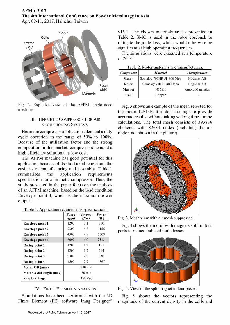
Fig. 3 shows an example of the mesh selected for
the motor 12S14P. It is dense enough to provide
accurate results, without taking so long time for the
calculations. The total mesh consists of 393886
elements with 82634 nodes (including the air
region not shown in the picture).
Fig. 3. Mesh view with air mesh suppressed.
Fig. 4 shows the motor with magnets split in four
parts to reduce induced joule losses.
Fig. 4. View of the split magnet in four pieces.
Fig. 5 shows the vectors representing the
magnitude of the current density in the coils and
Presented at APMA, Taiwan on April 10, 2017

APMA-2017
The 4th International Conference on Powder Metallurgy in Asia
Apr. 09-11, 2017, Hsinchu, Taiwan
magnets. Note that the current density is minor in
the magnets, meaning that the split method is
helping to reduce the induced current, and hence
the magnet losses.
Fig. 5. Current density in the coils and magnets.
Fig. 6 shows the magnetic flux density in the
stator. Some small regions in the upper part of the
stator teeth is saturated above 1.7 T. Most of the
volume of the stator has low flux density, helping
to keep the iron loss low.
Fig. 6. Magnetic Flux Density in the stator.
V. RESULTS
The total active mass is summarised in Table 3.
The total weight is about 1.5 kg, given the output
power is 2.6 kW, this machine has the power
density of 1.73 kW/kg. In this study, the current
density was limited to 5.0 A/mm2. If more current
density were allowed, e.g. 15.0 A/mm2, the power
density would increase to 2.62 kW/kg.
Table 3. Motor active mass summary. Per Component Total
Stator SMC (g) 616.32 616.32
Rotor SMC (g) 190.37 190.37
Coil (g) 50.18 602.17
Magnet (g) 6.89 96.42
Motor active mass (g) - 1505.29
Table 4 outlines the dimensions of the motor. The
simulations were performed at no load and rated
load condition. Table 5 shows the parameters of
the machine.
Table 4. Machine dimensions.
Outer diameter (mm) 120.00
Inner diameter (mm) 53.80
Total Axial Length (mm) 35.60
Air Gap (mm) 1.00
Magnet Span (degree) 140.00
Magnet Depth (mm) 2.60
Rotor Coreback Depth (mm) 4.00
Stator Coreback Depth (mm) 4.00
Stator Tooth Height (mm) 24.00
Coil Width (mm) 5.10
Bobbin Insulation Thickness (mm) 0.75
Table 5. Machine parameters.
Phases 3
Poles 14
Slots (coils) 12
Frequency (Hz) 700
Max Current density (A/mm2) 5.00
Coil Fill factor 0.67
Wire diameter (bare) (mm) 0.80
Number of strands in parallel 3
Number of turns 51
The results for torque and voltage are shown in
Table 6.
Table 6. Torque and voltage summary.
Parameter Value
No
loa
d RMS voltage of back EMF (V) 115.56
Peak Line-Line Back EMF Voltage (V) 299.31
Peak Cogging Torque (Nm) 0.07
Ra
ted
loa
d Average torque @ rated current (Nm) 4.12
Torque ripple @ rated current (%) 2.39
Peak line-line load voltage (V) 299.86
Table 7 shows the inductance at direct and
quadrature axis. Note that this AFPM machine has
very little saliency.
Table 7. Inductance at direct and quadrature axis.
Inductance Q-axis (mH) 1.91
Inductance D-axis (mH) 1.96
Jmag provides, in the iron loss analysis, the
hysteresis and particle losses separately. The losses
Presented at APMA, Taiwan on April 10, 2017

APMA-2017
The 4th International Conference on Powder Metallurgy in Asia
Apr. 09-11, 2017, Hsinchu, Taiwan
are presented in Table 8. Particle losses should not
be confused with the bulk joule losses that are
dependent on the resistivity of the SMC material
and the geometry of the SMC component.
Table 8. Losses at rated load.
Joule loss (W) Iron Loss (W)
Bulk Hysteresis Particle
Stator SMC 3.54 41.22 13.29
Rotor SMC 0.13 4.24 2.24
Magnets 10.80 - -
Coils 32.36 - -
TOTAL 46.82 45.45 15.53
Table 9 resumes the performance according to
the simulations. The efficiency at the Envelope
point 4 in Table 1 is significantly high, reaching
96% neglecting friction and windage losses.
Table 9. Motor performance at rated load.
Current
RMS (A)
Speed
(rpm)
Total Loss
(W)
Torque
(Nm)
Pm
(W)
Eff
(%)
7.54 6000 108 4.12 2591 96
Fig. 7 shows the back EMF at 6000 RPM for one
electric period.
Fig. 7. Back EMF waveform at 6000 RPM.
VI. CONCLUSION
This paper presented the performance analysis by
means of 3D FE of an AFPM machine. The
topology shown is suitable for compressor
applications because of its compact axial length,
high efficiency and ease of assembly in mass
production.
The power density can be substantially increased
if allowed to use higher current density, which in
this study was limited to 5.0 A/mm2.
Single-sided AFPM machines have similar
behaviour to conventional Brushless DC machines,
i.e. standard controllers and control techniques can
be used.
REFERENCES
[1] G. Cvetkovski, L. Petkovska, M. Cundev, and
S. Gair, “Improved design of a novel PM disk
motor by using soft magnetic composite
material,” IEEE Trans. Magn., vol. 38, no. 5,
pp. 3165–3167, 2002.
[2] A. G. Jack, B. C. Mecrow, G. Nord, and P. G.
Dickinso, “Axial Flux Motors Using
Compacted Insulated Iron Powder and
Laminations - Design and Test Results,” IEEE
Int. Conf. Electr. Mach. Drives, 2005., pp. 378–
385, 2005.
[3] J. G. Washington, G. J. Atkinson, N. J. Baker,
A. G. Jack, B. C. Mecrow, B. B. Jensen, L.
Pennander, G. L. Nord, and L. Sjoberg, “Three-
Phase Modulated Pole Machine Topologies
Utilizing Mutual Flux Paths,” IEEE Trans.
Energy Convers., vol. 27, no. 2, pp. 507–515,
Jun. 2012.
[4] C. Pompermaier, K. Kalluf, A. Zambonetti, M.
V. Ferreira da Luz, and I. Boldea, “Small
Linear PM Oscillatory Motor: Magnetic Circuit
Modeling Corrected by Axisymmetric 2-D
FEM and Experimental Characterization,”
IEEE Trans. Ind. Electron., vol. 59, no. 3, pp.
1389–1396, Mar. 2012.
[5] O. Maloberti, R. Figueredo, C. Marchand, Y.
Choua, D. Condamin, L. Kobylanski, and E.
Bomme, “3D-2D Dynamic Magnetic Modeling
of an Axial Flux Permanent Magnet Motor
With Soft Magnetic Composites for Hybrid
Electric Vehicles,” IEEE Trans. Magn., vol. 50,
no. 6, pp. 1–11, 2014.
[6] C. Liu, J. Zhu, Y. Wang, G. Lei, Y. Guo, and
X. Liu, “A low-cost permanent magnet
synchorous motor with SMC and ferrite PM,”
2014 17th Int. Conf. Electr. Mach. Syst. ICEMS
2014, pp. 397–400, 2015.
[7] J. F. Gieras, R.-J. Wang, and M. J. Kamper,
Axial Flux Permanent Magnet Brushless
Machines, 2nd ed. Springer, 2008.
Presented at APMA, Taiwan on April 10, 2017