Users Manual for Updated Computer Code for Axial-Flow ... · An existing computer code that...
24
NASA Contractor Report 189171 //J -G/ (9. a3 Users Manual for Updated Computer Code for Axial-Flow Compressor Conceptual Design Arthur J. Glassman University of Toledo Toledo, Ohio July 1992 = Prepared for Lewis Research Center Under Grant NAG3-1165 National Aeronautics and Space Administration (NASA-CR-189171) CnMPUT_R CODE FOk CqNCEPTUAL DESIGN Univ.) 23 p USERS MANUAL FOn UPDATED AXIAL-FLOW COMPRESSOR F_-l--Report (Toledo G]/ol N92-50207 Unclas 0111067 https://ntrs.nasa.gov/search.jsp?R=19920020964 2020-03-16T03:21:10+00:00Z
Transcript of Users Manual for Updated Computer Code for Axial-Flow ... · An existing computer code that...
NASA Contractor Report 189171
//J -G/
(9. a3
Users Manual for Updated ComputerCode for Axial-Flow Compressor
Conceptual Design
Arthur J. Glassman
University of Toledo
Toledo, Ohio
July 1992
=
Prepared forLewis Research Center
Under Grant NAG3-1165
National Aeronautics and
Space Administration
(NASA-CR-189171)CnMPUT_R CODE FOk
CqNCEPTUAL DESIGN
Univ.) 23 p
USERS MANUAL FOn UPDATED
AXIAL-FLOW COMPRESSOR
F_-l--Report (Toledo
G]/ol
N92-50207
Unclas
0111067
https://ntrs.nasa.gov/search.jsp?R=19920020964 2020-03-16T03:21:10+00:00Z

qp- _
t1
2
i_

USERS MANUAL FOR UPDATED COMPUTER CODE FOR AXIAL-FLOW
COMPRESSOR CONCEPTUAL DESIGN
Arthur J. Glassman
The UniversityofToledo
Toledo,Ohio 43606
OOt_
SUMMARY
An existing computer code that determines the flow path for an axial-flow compressor either for a
given number of stages or for a given overall pressure ratio was modified for use in air-breathing engine
conceptual design studies. This code uses a rapid approximate design methodology that is based on isen-
tropic simple radial equilibrium. Calculations are performed at constant-span-fracti0n locations from tipto hub. Energy addition per stage is controlled by specifying the maximum allowable values for several
aerodynamic design parameters.
New modeling was introduced to the code to overcome perceived limitations. Specific changes
included variable rather than constant tip radius, flow path inclination added to the continuity equation,
input of mass flow rate directly rather than indirectly as inlet axial velocity, solution for the exact value
of overall pressure ratio rather than for any value that met or exceeded it, and internal computation of
efficiency rather than the use of input values. The modified code was shown to be capable of computing
efficiencies that are compatible with those of five multistage compressors and one fan that were tested
experimentally.
This report serves as a users manual for the revised code, which is named CSPAN, an acronym for
C_ompressor s__pPanlineANalysis. The modeling modifications, including two internal loss correlations, arepresented. Program input and output are described. A sample case for a multistage compressor isincluded.
INTRODUCTION
Performing engine studies requires the capability to produce conceptual designs of the componentsin order to determine geometry, performance, and weight. One major component of alr-breathing turbine
engines is the compressor. The typical compressor "design" code enables a study of the interrelationship
of the number of stages, the flow path radii, the gas velocities, the flow angles, and the resultant varia-
tion of compressor efficiency. A computer code capable of performing this function in a rapid approximate
manner was selected as being consistent with the needs of engine conceptual design. This code (ref. 1),which is based on isentropic simple radial equilibrium, was one of four compressor analysis codes devel-
oped under NASA contract about 25 years ago. The other three codes, two design (refs. 2 and 3) and one
off-design (ref. 4), were streamline analyses accounting for full radial equilibrium.
An evaluation of the reference 1 code indicated several limitations to its usefulness for the con-
ceptual sizing of engine compressors. The design was restricted to a constant tip radius, and flowpath
inclination was not accounted for in the continuity calculation. In addition, the user was unable to
directly specify a mass flow rate or an exact overall pressure ratio. Finally, stage efficiency had to be
*Resident Research Associate--NASA Lewis Research Center, Cleveland, Ohio.
estimatedbeforehandbecauseit wasa requiredinput, and there was no provision for inlet guide vane
loss. Consequently, the code was modified to overcome these deficiencies.
This report serves as a users manual for the revised code, which is named CSPAN, an acronym for
Compressor SPanline ANalysis. The modeling changes are presented herein. Computed efficiencies arecompared with test results from five multistage compressors and one fan. Program input and output are
described. A sample case for a multistage compressor is included.
B
b
C
D
D
E
f
g
H
J
k
M
n
P
R
T
U
V
w
Z
P
ff
_d
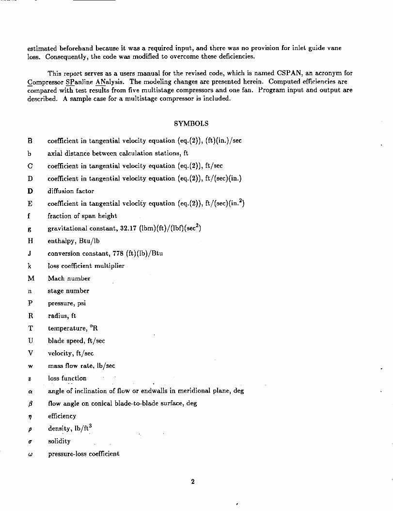
SYMBOLS
coefficient in tangential velocity equation (eq.(2)), (ft)(in.)/sec
axial distance between calculation stations, ft
coefficient in tangential velocity equation (eq.(2)), ft/sec
coefficient in tangential velocity equation (eq.(2)), ft/(sec)(in.)
diffusion factor
coefficient in tangential velocity equation (eq.(2)), ft/(sec)(in. 2)
fraction of span height
gravitational constant, 32.17 (Ibm) (ft) /(lbf) (sec 2)
enthalpy, Btu/lb
conversion constant, 778 (ft)(lb)/Btu
loss coefficient multiplier
Mach number
stage number
pressure, psi
radius, ft
temperature, OR
blade speed, ft/sec
velocity, ft/sec
mass flow rate, lb/sec
loss function
angle of inclination of flow or endwalls in meridional plane, deg
flow angle on conical blade-to-blade_surface, deg
efficiency
density, lb/ft a
solidity
pressure-loss coefficient
2
Subscripts:
avg average
cor corrected
e equivalent
ex exit
g geometric
H hub
id ideal
in inlet
inp input
ns normal shock
ov overall
p polytropic
pr profile
R rotor
S stator
s static
sh shock
stg stage
T tip
t total
z meridionalcomponent
0 tangential component
1 rotor inlet
2 rotor exit
2D two dimensional
3 stator exit
3D three dimensional
Superscripts:
' relative
* uncorrected value
3

METHOD OF ANALYSIS
The computer code of reference 1 was developed for making parametric studies of advanced multi-
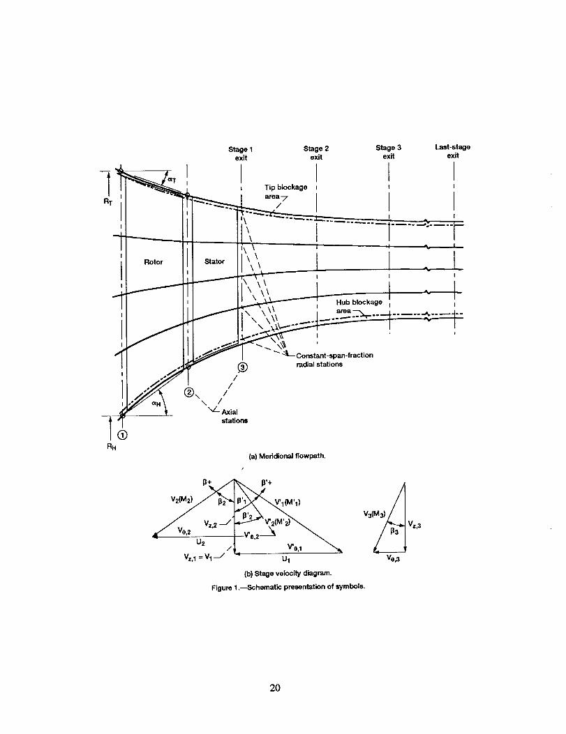
stage axial-flow compressors. This code determines the meridional flow path for given design specifica-tions of either the number of stages or the overall pressure ratio. Such a flow path is illustrated in
figure l(a), where the stage station locations and some of the geometry variables are defined. A typicalstage velocity diagram including the symbols for all velocities and angles is shown in figure l(b).
The flow-physics model and the solution procedure are described in detail in reference 1. These are
briefly summarized herein, and then the revisions made to improve the code's usefulness for air-breathing
engine conceptual design studies are described.
Flow-Physics Model
The radial equation of motion is based on isentropic simple radial equilibrium (no effects of stream-
line slope and curvature and radially constant entropy). Consequently, at each axial station
dH t V e d(RV0) dV zgj_ = _ + + Vz - (1)
dR R dR dR
where the variation of tangential velocity with radius is
V0=B
+ C + DR + ER 2 (2)R
Equations (1) and (2) along with continuity
W =27rfRR: pV_R dR (3)
and stage energy addition
gJ AH t = A(UV0)
provide the basic flow-physics model.
Stage energy addition is determined either by specifying the tangential velocities (eq. (2)) at both
the rotor inlet and exit or by specifying the tangential velocity at the rotor inlet, the axial velocity ratio
across the rotor tip, and a maximum value for the rotor tip diffusion factor,
t I I
V 2 V0,1 - VO, 2
DR, T = 1 - -- +I I
V I 2aV I
(4)
(5)

from which rotor-exit tangential velocity is obtained. In either case, the energy addition is reduced if
limit values are exceeded for stator-inlet hub Mach number, stator hub diffusion factor, or rotor-exit hub
relative flow angle. Energy addition is then related to rotor and stage pressure ratios by input values of
rotor and stage polytropic efficiencies, respectively.
Computation proceeds stage by stage until either a given number of stages is reached or a given
overall pressure ratio is met or exceeded. The flow path geometry evolves from the given inlet tip radius
and continuity and the specified limits for hub and tip ramp angles. Tip radius normally remains con-
stant and hub radius is computed. If the hub ramp angle limit is exceeded, the tip radius is reduced so
that the hub ramp angle is at its limit value.
Code Revisions
The code of reference 1 was evaluated for application to the conceptual design of compressors for
air-breathing engines. These conceptual designs serve as the basis for estimating engine weight and per-formance. It was found that the code's usefulness could be improved by revising some of its physical
modeling and solution procedures. The basic flow-physics modeling and energy-addition modeling were
retained as previously described except for the inclusion of flow path inclination in the continuity equa-
tion (eq. (3)) as discussed later in this section. All modeling changes are described in this section.
Tip radius.--With the original methodology the compressor design was executed with a constant
tip radius unless a hub ramp angle constraint was exceeded. Many advanced designs require tip radius
reductions in order to provide adequate blade height at the exit. Therefore, an input was added to the
code that allowed direct specification of the tip radius change across each blade row. The hub ramp
angle limit was kept as a constraint in order to avoid excessive wall slope and if exceeded would result in
further tip radius reduction.
Continuity.--In the original model the velocity is expressed in terms of two components
V 2 = V 2 + 2 (6)z V0
The V z term is referred to as "axial" velocity and is used as such for continuity (eq. (3)) even though
there can be significant inclination in parts of the flow path (especially in the hub region of the inlet
stages). As used in equation (6), V z is actually a meridional velocity (the resultant of axial and radial
components). Considering V z as a meridional velocity herein, the continuity equation is revised to
w = 2_ f RTRH pV z cos a R dR (7)
The streamline angle of inclination a is estimated as the slope of the constant-span-fraction line through
the previous blade row.
Mass flow rate.--The original code required as input a value for inlet tip axial velocity, which was
then used to compute a mass flow rate for the compressor. Because mass flow rate is usually specified for
an engine, it is preferable to use it rather than inlet axial velocity as the input. Therefore, the calculation
procedure was modified to enable a mass flow rate to be input and an iteration to be performed to find
the value of inlet tip axial velocity that provided the given mass flow rate.
5
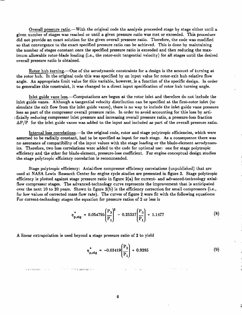
Overallpressureratio.--Withthe originalcode the analysisproceeded stageby stageeitheruntila
given number ofstageswas reached or untila given pressureratiowas met or exceeded. This procedure
did not provide an exactsolutionforthe given overallpressureratio.Therefore,the code was modified
so thatconvergenceto the exact specifiedpressureratiocan be achieved. This isdone by maintaining
the number ofstagesconstantonce the specifiedpressureratioisexceeded and then reducingthe max-
imum allowablerotor-bladeloading(i.e.,the rotor-exittangentialvelocity)forallstagesuntilthe desired
overallpressureratioisobtained.
Rotor hub turning.--One ofthe aerodynamic constraintsfora designisthe amount ofturningat
the rotorhub. In the originalcode thiswas specifiedby an input value forrotor-exithub relativeflow
angle. An appropriatelimitvalue forthisvariable,however, isa functionof the specificdesign. In order
to generalizethisconstraint,itwas changed to a directinput specificationof rotorhub turningangle.
Inletguide vane loss.--Computationsare begun at the rotorinletand thereforedo not includethe
inletguide vanes. Although a tangentialvelocitydistributioncan be specifiedat the first-rotorinlet(to
simulatethe exitflowfrom the inletguide vanes),thereisno way to includethe inletguide vane pressure
lossas partof the compressor overallpressureratio.In order to avoid accountingfor thislossby arti-
-flciallyreducingcompressor inletpressureand increasingoverallpressureratio,a pressure-lossfraction
AP/P forthe inletguide vanes was added to the input and includedas part ofthe overallpressureratio.
Internallosscorrelations.--Inthe originalcode,rotorand stagepolytropicefficiencies,which were
assumed to be radiallyconstant,had to be specifiedas input foreach stage. As a consequence therewas
no assuranceofcompatibilityof the input valueswith the stageloadingor the blade-elementaerodynam-
ics.Therefore,two losscorrelationswere added to the code foroptionaluse: one forstagepolytropic
efficiencyand the other forblade-element,pressure-losscoefficient.For engineconceptualdesignstudies
the stagepolytropicefficiencycorrelationisrecommended.
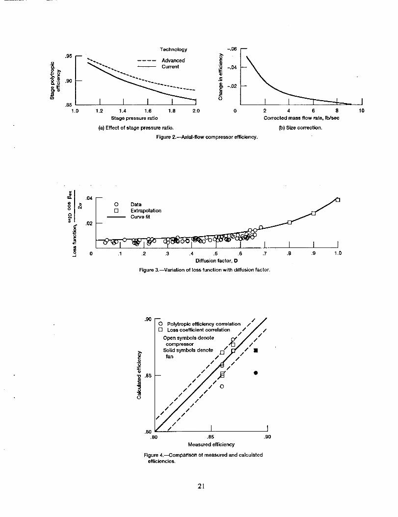
Stage polytropicefficiency:Axial-flowcompressor efficiencycorrelations(unpublished)thatare
used at NASA Lewis Research Center for enginecyclestudiesare presentedinfigure2. Stage polytropic
efficiencyisplottedagainststage pressureratioin figure2(a)forcurrent-and advanced-technologyaxial-
flow compressor stages.The advanced-technologycurve representsthe improvement that isanticipated
over the next 10 to 20 years. Shown in figure2(b)isthe efficiencycorrectionforsmall compressors (i.e.,
forlow valuesofcorrectedmass flowrate).The curvesoffigure2 were fitwith the followingequations:
For current-technologystagesthe equation forpressureratiosof 2 or lessis
. 'r/P'stg _PIJ _PlJ
(s)
A linearextrapolationisused beyond a stagepressureratioof 2 to yield
_.,stg_* = -0.03419 + 0.9285 (9)
6

For advanced-technology stages the equation for pressure ratios of 2 or less is
IF3}rlp,stg = 0.047322 - 0.21668 + 1.1241Lp1)
(10)
An extrapolation beyond a stage pressure ratio of 2 yields
* = -0.027392 + 0.93478r/p,stg
(11)
For corrected mass flow rates of less than 10 lb/sec, efficiency is reduced to account for size effects
(clearances, surface finish, etc.). The size correction for corrected mass flow rates between 1.5 and
10 lb/sec is
AsTp,stg ffi 0.56826)< 10-3 Wcor - 0.62224 x 10-30.050603
m
Wcor
(12)
and linear extrapolation for flow rates below 1.5 lb/sec yields
ATIp,stg = 0.01767 Wco r - 0.06(13)
The corrected flow rate in equations (12) and (13) is defined as
WCO r
w ITin/518.7 (14)
Pin/14.7
After correcting for size, the resultant value of stage polytropic efficiency can be adjusted by an input loss
multiplier as follows:
[ . ]_]p,stg ffi 1 - kin p 1 - (_/p,stg + A_/p,stg )(15)
Assuming that two-thirds of the stage loss occurs in the rotor, the rotor polytropic efficiency is
r]p,R-- 1 - --2( 1 -_]p,stg) (16)3
This approximation, which is based on experience, affects only the hub radius at rotor exits. Equa-
tions (8) to (16) were incorporated into the code as one optional method for computing efficiency.
7
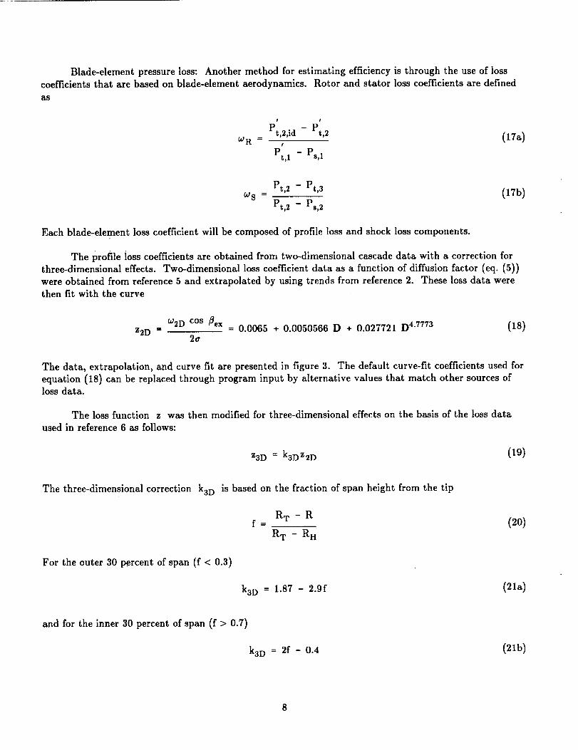
Blade-elementpressure loss: Another method for estimating efficiency is through the use of loss
coefficients that are based on blade-element aerodynamics. Rotor and stator loss coefficients are defined
as
I F
WR = Pt,2,id - Pt,2 (17a)I
Pt,1 - Ps,1
°JS = Pt,2 - Pt,3 (17b)
Pt,2 - Ps,2
Each blade-element loss coefficient will be composed of profile loss and shock loss components.
The profile ioss coefficients are obtained from two-dimensional cascade data with a correction forthree-dimensional effects. Two-dimensional loss coefficient data as a function of diffusion factor (eq. (5))
were obtained from reference 5 and extrapolated by using trends from reference 2. These loss data were
then fit with the curve
Z2D ffi
W2D cos flex
2a
= 0.0065 + 0.0050566 D + 0.027721 D 4"7773 (18)
The data, extrapolation, and curve fit are presented in figure 3. The default curve-fit coefficients used for
equation (18) can be replaced through program input by alternative values that match other sources ofloss data.
The loss function z was then modified for three-dimensional effects on the basis of the loss data
used in reference 6 as follows:
Z3D = k3DZ2D (19)
The three-dimensional correction k3D is based on the fraction of span height from the tip
R T - Rf=
R w - R H
For the outer 30 percent of span (f < 0.3)
k3D ffi 1.87 - 2.9f
(20)
(21a)
and for the inner 30 percent of span (f > 0.7)
k3D = 2f - 0.4 (21b)

There is no correction for the center 40 percent of blade span.
The profile loss function was increased by 50 percent on the basis of experimental compressor per-
formance (see next subsection) and can be arbitrarily adjusted further by an input loss multiplier.
Zpr = 1.5kinpZ3D (22)
The profile loss coefficient is then
Wpr =2aZpr
COS _ex
(23)
The shock loss coefficient is based on the methodology of reference 7, wherein the passage-shock
loss is taken as the normal-shock loss from the arithmetic average of the inlet and the estimated peaksuction-surface Mach numbers. The authors of reference 6 state that a shock loss so determined is
excessive, and they recommend that the normal-shock loss be divided by the square of the average Mach
number. Therefore, the rotor shock loss coefficient is
F F
I - Pt,ns/Pt,1 (24)i_0118 ----
t
1 - PB,1/Pt,I
and
(_nB
_sh = (25)
Although a shock also can theoretically occur in the stator, aerodynamic constraints that are imposed on
the design normally prevent this.
The blade-element overall loss coefficient is then
_gov = Wpr + Wsh(26)
and the blade-row exit total pressure is determined from this loss coefficient.
Comparison with experimental performance: In order to test the loss models, calculated perfor-mance was compared with experimental performance for five multistage compressors (refs. 8 to 12) and
one fan (ref. 13). The overall design features of these machines are presented in table I along with esti-mates of the design-point efficiencies that are based on test data.
The data reportedinreferences8 to 13 are forresearchor early-developmentcompressorsand
thereforeare not representativeof the design-pointefficiencylevelsthat are achievablein developed
engines. Consequently,forthe purposes of thiscomparison the measured design-pointefficienciesof the
9

referenced compressors were adjusted to a projected design-point value. The projected value was taken as
the maximum efficiency either at design speed or, if there appeared to be a significant mismatch at design
speed, at a somewhat lower speed. This adjustment procedure is largely subjective, but there appear to
be no published data on the performance of fully developed current- and advanced-technology compressors.
The referenced compressors were modeled for the CSPAN program, which was run using both loss
models. The design-point efficiency comparison of calculated and measured efficiencies is presented in fig-ure 4. For the polytropic efficiency correlation the calculated and measured efficiencies were within one
point of each other for all five multistage compressors and were within two points for the fan. For the
pressure-loss coefficient correlation the multiplier of 1.5 introduced into equation (22) was based on the
best overall comparison between calculated and measured values. With this value, four of the compres-sors compared to within about one point, but the calculated efficiency of the fan was more than three
points low. These loss models seem to yield reasonable estimates for multistage compressors, but some
adjustment in the input loss multiplier kin p may be needed for fans.
DESCRIPTION OF INPUT AND OUTPUT
This section presents a detailed description of input and output for program CSPAN. Included
with the input and output is a sample case for a five-stage transonic compressor.
Input
The input, which is read on unit 05, consists of a title line and one NAMELIST dataset. Input for
the sample case is presented in table II. The title, which is printed as a heading on the output file, cancontain up to 71 characters located anywhere in columns 2 through 72 on the title line. A title, even if it
is left blank, must be the first record of the input data.
The physical data and option switches are input in data sets having the NAMELIST name NAME. The
variables that compose NAME are defined herein along with units and default values. They are pre-
sented in order as general inputs, inlet inputs, rotor inputs, and stator inputs.
General:
CP
MW
GAM
RCLIM
NSLIM
N
ICV
specific heat of working fluid, Btu/(lb)(°R)
molecular weight of working fluid, Ib/(lb mol)
specific heat ratio
limit value for overall pressure ratio
limit value for number of stages
number of calculation locations from tip to hub
pressure ratio convergence switch (default : 1)
0--accepts overall pressure ratio equal to or greater than RCLIM as asolution
1--converges to overall pressure ratio equal to RCLIM
10
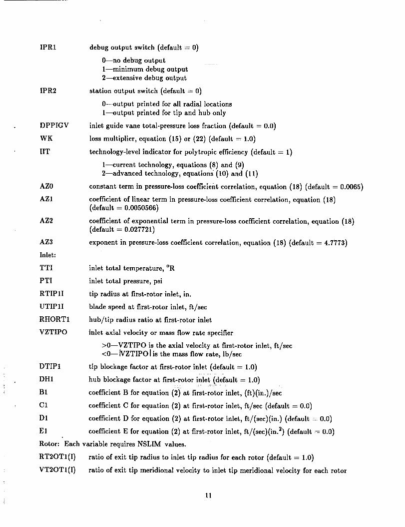
IPR1
IPR2
DPPIGV
WK
IIT
AZ0
AZ1
AZ2
AZ3
Inlet:
TTI
PTI
RTIPII
UTIPII
RHORT1
VZTIPO
debug output switch (default= 0)
O--no debug output
1--minimum debug output
2--extensivedebug output
stationoutput switch (default= 0)
0--output printedforallradiallocations
1--output printedfortipand hub only
inletguide vane total-pressurelossfraction(default= 0.0)
lossmultiplier,equation (15)or (22)(default--1.0)
technology-levelindicatorforpolytropicefficiency(default= 1)
1--currenttechnology,equations(8)and (9)
2--advanced technology,equations(10)and (11)
constant term in pressure-losscoefficientcorrelation,equation (18) (default= 0.0065)
coefficientoflinearterm in pressure-losscoefficientcorrelation,equation (18)
(default = 0.0050566)
coefficient of exponential term in pressure-loss coefficient correlation, equation (18)(default = 0.027721)
exponent in pressure-loss coefficient correlation, equation (18) (default = 4.7773)
inlet total temperature, °R
inlet total pressure, psi
tip radius at first-rotor inlet, in.
blade speed at first-rotor inlet, ft/sec
hub/tip radius ratio at first-rotor inlet
inlet axial velocity or mass flow rate specifier
>0--VZTIPO is the axial velocity at first-rotor inlet, ft/sec<0--_VZTIPO [is the mass flow rate, lb/sec
DTIP1 tip blockage factor at first-rotor inlet (default = 1.0)
DH1 hub blockage factor at first-rotor inlet (default = 1.0)
B1 coefficient B for equation (2)at first-rotor inlet, (ft)(in.)/sec
C1 coefficient C for equation (2) at first-rotor inlet, ft/sec (default -- 0.0)
D1 coefficient D for equation (2) at first-rotor inlet, ft/(sec)(in.) (default - 0.0)
E1 coefficient E for equation (2) at first-rotor inlet, ft/(sec)(in. 2) (default = 0.0)
Rotor: Each variable requires NSLIM values.
RT2OTI(I) ratio of exit tip radius to inlet tip radius for each rotor (default = 1.0)
VT2OTI(I) ratio of exit tip meridional velocity to inlet tip meridional velocity for each rotor
11

NPRI(I)
SRTIP(I)
ARO(I)
DTIP2(I)
DH2(1)
ARHD(1)
ARTD(I)
DRT(1)
BO(1)
c2(I)
D2(I)
E2(I)
BPSD(I)
efficiency specifier for each rotor
> 0.0--input value is rotor polytropic efficiency
= 0.O--polytropic efficiency correlation is used
= -1.0--pressure-loss coefficient correlation is used
rotor tip solidity
rotor aspect ratio (based on axial chord)
tip blockage factor at rotor exit (default = 1.0)
hub blockage factor at rotor exit (default = 1.0)
rotor hub ramp angle limit, deg
rotor tip ramp angle limit, deg
rotor tip diffusion factor maximum value
rotor-exit tangential velocity specifier
= 0.0--rotor tip exit tangential velocity determined from rotor tip
diffusion factor by equation (5)
> 0.0--coefficient B for equation (2) at rotor exit, (ft)(in.)/sec
coefficient C for equation (2) at rotor exit, ft/sec (default = 0.0)
coefficient D for equation (2) at rotor exit, ft/(sec)(in.) (default = 0.0)
coefficient E for equation (2) at rotor exit, ft/(sec)(in. 2) (default = 0.0)
limit value for rotor hub turning, deg
Stator:
RT3OT2(I)
VT3OT2(I)
NPSI(I)
SSH(I)
ASO(I)
DTIP3(I)
DH3(I)
ASHD(I)
ASTD(I)
DSH(I)
MSH(I)
B3(I)
C3(I)
Each variable requires NSLIM values.
ratio of exit tip radius to inlet tip radius for each stator (default = 1.0)
ratio of exit tip meridional velocity to inlet tip meridional velocity for each stator
efficiency specifier for each stage
> 0.0--input value is stage polytropic efficiency
= 0.0--polytropic efficiency correlation is used
= -1.0--pressure-loss coefficient correlation is used
stator hub solidity
stator aspect ratio (based on axial chord)
tip blockage factor at stator exit (default = 1.0)
hub blockage factor at stator exit (default = 1.0)
stator hub ramp angle limit, deg
stator tip ramp angle limit, deg
limit value for stator hub diffusion factor
limit value for stator hub inlet Mach number
coefficient B for equation (2) at stator exit, (ft)(in.)/sec
coefficient C for equation (2) at stator exit, ft/sec (default = 0.0)
12

D3(I)
E3(I)
coefficient D for equation (2) at stator exit, ft/(sec)(in.) (default = 0.0)
coefficient E for equation (2) at stator exit, ft/(sec)(in. 2) (default = 0.0)
Output
Program output consists of a main output file written to unit 06 and, if applicable, a brief
pressure-ratio convergence file written to unit 08. The main output presents either the results of a
successful design calculation or an error message indicating the nature of the failure to find a solution
that is consistent with the design specifications.
Outputs corresponding to the sample input of table II are presented in tables III and IV. The
pressure-ratio convergence output, shown in table III, is most useful when sent to the terminal so that a
convergence problem can be immediately detected and the computation halted. Convergence problems,
however, have not occurred for any of the six cases tested (table I). As shown in table III, convergence toa pressure ratio of 5 required four iterations. Shown in the output are the number of stages followed by
one line for each iteration displaying the rotor tip diffusion reduction factor (DRTK), the compressor
pressure ratio (CPR), and the compressor adiabatic efficiency (EFF).
The main output is presented in table IV. For brevity in displaying the output, calculations were
performed at only three radial locations (N = 3), and only the data for stages 1 and 5 are included along
with the overall and inlet information. The first line of output in table IV is the title; it is followed by
identification of the loss model used for this case. Then, the general inputs and the inlet inputs areprinted. The values displayed are clearly identified.
The next output line in table IV states that one of the aerodynamic limits, in this case the stator
hub Mach number, was exceeded in the next stage, which in this case is the first stage. As a result, the
rotor tip diffusion factor was reduced from its maximum allowable value until the Mach number limit
was just satisfied. The consequence of this is a reduction in stage pressure ratio.
The next block of output in table IV is the data for stage 1. This includes the rotor input, the
stator input, the stage performance and geometry, and the detailed aerodynamic results at the rotor inlet,
the rotor exit, and the stator exit. Note that the rotor and stator input sections include the rotor andstage polytropic efficiencies, respectively, which were_etermined in this case from the internal correla-
tion. Under stage output data are the overall values of pressure ratio, temperature ratio, and adiabatic
efficiency followed by the stage values, which are the _same since this is the first stage. Also displayed are
the rotor and stator tip and hub radii, the axial lengths, and the tip and hub ramp angles. Finally, at
each of the three axial stations for the stage are presented among other parameters, the temperatures and
pressures, the absolute and relative velocities, the absolute and relative flow angles, the diffusion factors,and the loss coefficients at each of the radial calculation locations.
The stage data format is identical for each stage; therefore, the "STAGE DATA" output for
stages 2, 3, and 4 were omitted from table IV. Shown next is the data for stage 5. The USTAGEOUTPUT DATA" show that the overall pressure ratio of 5 has been achieved with an overall efficiency
of 0.8775. For this constant-tip-radius (10 in.) design, the hub radius increased from 5.0 in. at the first-rotor inlet to 8.5 in. at the last-stator exit. The last line of output states that the specified overall pres-
sure ratio has been achieved. If the specified pressure ratio had not been achieved, the last-line message
would be that the maximum number of stages had been reached.
13

SUMMARY OF RESULTS
An existing computer code that determines the flow path for an axial-flow compressor either for a
given number of stages or for a given overall pressure ratio was selected for use in air-breathing engine
conceptual design studies. This code uses a rapid approximate design methodology that is based on isen-
tropic simple radial equilibrium. Calculations are performed at a number of constant-span-fraction loca-
tions from tip to hub at each blade-row inlet and exit. Energy addition per stage is controlled by amaximum allowable value for the rotor tip diffusion factor, which is reduced if limit values are exceeded
for the stator hub inlet Mach number, the stator hub diffusion factor, or the rotor hub turning angle.
This code was modified to make it easier to use for the conceptual study of engine compressors.
The rapid approximate design methodology was retained and new modeling was introduced to overcome
perceived limitations. The limitations and associated modifications were as follows:
1. Unless the given hub ramp angle limit was exceeded, the tip radius had remained constant. A
tip radius change for each blade row can now be specified through input.
2. The throughflow component of velocity had been assumed to be purely axial for the continuity
calculation. An internally computed flow path inclination angle was added to the continuity equation.
3. Mass flow rate had been computed from an input value of inlet axial velocity. A new algorithm
allows mass flow rate to be input and the proper value of inlet axial velocity to be found by iteration.
4. Any case wherein the overall pressure ratio met or exceeded the specified value had been taken
to be an acceptable solution. Convergence to the exact value of overall pressure ratio can now beachieved.
5. Rotor and stage polytropic efflciencies had to be input for each stage. Two internal loss cor-relations were added to the code as alternative ways to specify performance: One is for the stage poly-
tropic efficiency and the other is for the blade-element, pressure-loss coefficient. For engine conceptual
design studies the stage polytropic efficiency correlation is recommended.
6. There had been no provision to include inlet guide vane pressure loss as part of the overall pres-
sure ratio. An input pressure-loss fraction for the inlet guide vanes has been added.
The modified code was tested by comparison with five multistage compressors and one fan for
which experimental data were available. The computed performance was found to be compatible with thetest results.
This report serves as a users manual for the modified code, which is named CSPAN, an acronym
for Compressor SPanline ANalysis. Program input and output are described. A sample case for a multi-
stage compressor is included.
1. Bryans, A.C.; and Miller, M.L.:sors. NASA CR-54530, 1967.
REFERENCES
Computer Program for Design of Multistage Axial-Flow Compres-
14

2. Creveling, H.F.; and Carmody, R.H.: Axial-Flow Compressor Design Computer Programs Incorporat-
ing Full Radial Equilibrium. Part I--Flow Path and Radial Distribution of Energy Specified
(Program 2). NASA CR-54532, 1968.
3. Creveling, H.F.; and Carmody, R.H.: Axial-Flow Compressor Design Computer Programs Incorporat-
ing Full Radial Equilibrium. Part II--Radial Distribution of Total Pressure and Flow Path or
Axial Velocity Ratio Specified. NASA CR-54531, 1968.
4. Creveling, H.F.; and Carmody, R.H.: Axial Flow Compressor Computer Program for Calculating Off-
Design Performance. NASA CR-72427, 1968.
5. Johnsen, I.A.; and Bullock, R.O., eds. Aerodynamic Design of Axial-Flow Compressors. NASA SP-36,1965.
6. Crouse, J.F.; and Gorrell, W.T.: Computer Program for Aerodynamic and Blading Design of
Multistage Axial-Flow Compressors. NASA TP-1946, 1981.
7. Schwenk, F.C.; Lewis, G.W.; and Hartmann, M.J.: A Preliminary Analysis of the Magnitude of
Shock Losses in Transonic Compressors. NACA RM-E57A30, 1957.
8. Geye, R.P.; Budinger, R.E.; and Volt, C.H.: Investigation of a High-Pressure-Ratio Eight-Stage
Axial-Flow Research Compressor With Two Transonic Inlet Stages. II--Preliminary Analysis ofOverall Performance. NACA RM-E53J06, 1953.
9. Kovach, K.; and Sandercock, D.M.: Experimental Investigation of a Five-Stage Axial-Flow Research
Compressor With Transonic Rotors. NACA RM-E54G01, 1954.
10. Steinke, R.J.: Design of 9.271-Pressure Ratio Five-Stage Core Compressor and Overall Performance
for First Three Stages. NASA TP-2597, 1986.
11. Hosney, W.M., et al.: High Pressure Compressor (ICLS/1OC) Component Performance Report.
NASA CR-174955, 1985.
12. Marchant, R.D.; Howe, D.C.; and Williams, M.C.: High-Pressure Compressor Performance Report.
NASA CR-182219, 1989.
13. Cline, S.J., et al.: Energy Efficient Engine Fan and Quarter-Stage Component Performance Report.
NASA CR-168070, 1982.
15
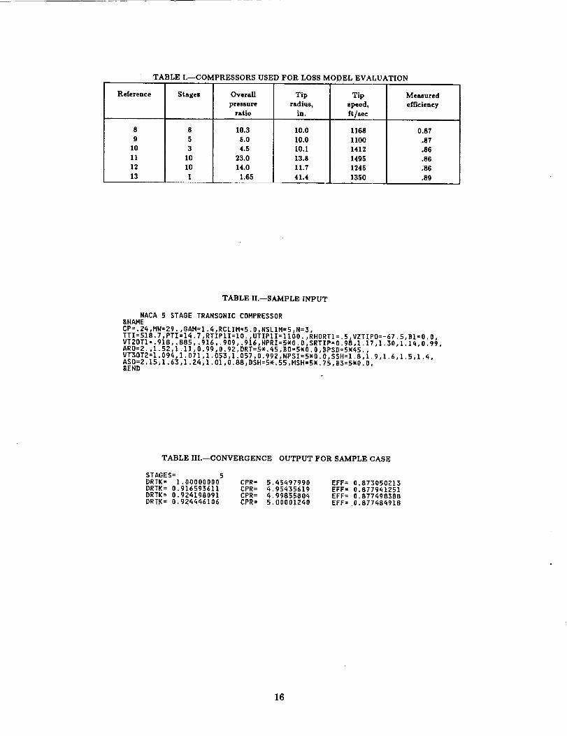
TABLE I.--COMPRESSORS USED FOR LOSS MODEL EVALUATION
Reference
8
9
10
11
12
13
Stages
8
5
3
10
10
I
Overall
pressure
Tip
radius,
ratio in.
10.3 I0.0
5.0 I0.0
4.5 10,1
23.0 13.8
14.0 11.7
1.65 41.4
Tip
speed,
ft/sec
1168
ll0O
1412
1495
1245
1350
Measured
efficiency
0.87
.87
.86
.86
.86
.89
TABLE II.--SAMPLE INPUT
NACA 5 STAGE TRANSONIC COMPRESSOR8NAME
CP=.Zq,MW=Zg.,GAM=1._,RCLIM=5.0,NSLIM=5,N=3,
TTI=518.7,PTI=14.7,RTIPlI=lO.,UTIPlI=1100.,RHORTl=.5,VZTIPO=-67.5,BI=O.O,VT20Tl=.g18,.B85,.916,.gog,.916,NPRI=5wO.O,SRTIP=O.98,1.i7,1.30,1.1_,O.99,ARO=2.,I.S2,1.11,0.gg,0.g2,DRT=S_._5,BO=5_O.O,_PSD=Sw_5.,
VTZOT2=l.094,1.071,1.053,I.057,D.g92,NPSI=5wO.O,SSH=l.8,1.9,1.6,1.5,1.q,ASO=2.15,1.63,l.2_,I.OI,O.88,DSH=5_.55,HSH=5W.75,B3=5wO.O,8ENB
TABLE IlL--CONVERGENCE OUTPUT FOR SAMPLE CASE
STAGES= 5
DRTK = 1.00000000 CPR= 5._5497990 EFF= 0.873050213DRTK= 0.916593611 CPR= _.95_35619 EFF= 0.877941251DRTK= 0.924198091 CPR= _.9985580_ EFF= 0.877_98388DRTK= 0.924_46106 CPR= 5.00001Z_0 EFF= 0.877_8_918
16

TABLE IV.--MAIN OUTPUT FOR SAMPLE CASE
NACA 5 STAGE TRANSONIC COMPRESSOR
LOSS MODEL: INTERNAL CORRELATION FOR STAGE POLYTROPIC EFFICIENCY
_ww I N L E T I H P 0 T D A T A XX:w
NO. RAD. NUMBER SP, HEAT MOL. WT. RATIO OF IN. TOT. TEMP. IN. TOT. PR. MASS AVG, TOT.STATIONS STAGES (BTU/(LB-R)) (MOLES) SP. HEAT (DEG. R) (PSI) PR. RATIO
3 5 0.2_00 29.0000 1._OOO 518.7000 1_,7000 5,0000
_R R O T 0 R I N L E T I H P U T D A T A _Ww
TIP RADIUS TIP WHEEL SPEED HUB TO TIP MASS FLOW TIP BLOCKAGE HUB BLOCKAGE(INCHES) (FT/SEC) RADIUS RATIO (LBYSEC) FACTOR FACTOR
10.0000 1100.0000 0.5000 67.5000 1.0000 1.0000
COEFFICIENTS IN TANGENTIAL VELOCITY EQUATION
B C D E
O,OOO0 O.O000 0.0000 O.O000
IGDEL
0.0
_w_ STATOR HUB MACH NO. LIMIT VIOLATED _wW
17

TABLE IV.--Continued.
w_w_ww S T A G E O A T A W_W_W_
STAGE NO. I
ww_ ROTOR INPUT DATA E_w
MERID VEL. POLYTROPIC SOLIDITYRATIO EFFICIENCY AT TIP
0.9180 0.9308 0.9800
MAX. TURNING TIPMAX ROTOR ANGLE ROTOR HUB RADIUS
DIF. FACTOR (DEGREES) RATIO
0.4160 45.0000 1.000
ASPECTRATIO
2.0000
TIP HUB MAX ANGLE MAX ANGLEBLOCKAGE BLOCKAGE HUB TAPER TIP TAPERFACTOR FACTOR (DEGREES) (DEGREES)
1.0000 1.0000 tO.BOO -20.000
COEFFICIENTS IN TANGENTIAL VELOCITY EQUATION
B C O E
0.0000 O,O000 0.0000 0.0000
HERID STAGE
VELOCITY POLYTROPIC SOLIDITYRATIO EFFICIENCY AT HUB
1.0940 0.8963 1,8000
TIPMAX. STATOR MAX HUB INLET RADIUSDIF. FACTOR HACH NUMBER RATIO
0.5500 0.7500 l,O00
_w STATOR INPUT DATA W_
TIPASPECTRATIO
2.1500
HUB MAX ANGLE MAX ANGLEBLOCKAGE _LOCKAGE HUB TAPER TIP TAPER
FACTOR FACTOR (DEGREES) (DEGREES)
1,oooo z.oooo 40.0000 -2o.0oooCOEFFICIENTS IN TANGENTIAL VELOCITY EQUATION
c D Eo.oooo O.OOO0 0.0000 0.0000
OVERALL OVERALLMASS AVE. MASS AVE.PR. RATIO TEMP. RATIO
1.4423 1.1238
ROTOR TIP ROTOR HUBRAD. I-G RAD. I-G(INCHES) (INCHES)
10.0000 5,0000
_--_-*_W S T A G E 0 U T P U T O A T A _W_--_--_w
MASS FLOW (LB/SEC) = 67.501
OVERALL MASS AVE. MASS AVE,MASS AVE. PRESSURE TEMPERATURE MASS AVE.
EFFICIENCY RATIO RATIO EFFICIENCY
0.8907 1.4423 1.1238 0.8907
ROTOR TIP ROTOR HUB STATOR TIP STATOR HUBRAD. 2_G RAO. 2-G RAD. 3-G RAD. 3-G(INCHES) (INCHES) (INCHES) (INCHES)
10.0000 5.8071 10.0000 6,4608
ROTOR TIP ROTOR HU3 STATOR TIP STATOR HUBRAHP ANGLE RAMP ANGLE RAMP AHGLE RAMP AHGLE
(DEGREES) (DEGREES) (DEGREES) (DEGREES)
0.0000 17.8924 0.0000 I8.5305
a
ROTOR STATORASPECT ASPECTRATIO RATIO
2.0000 2,1500
ROTOR PROJ. STATOR PROJ.LENGTH LENGTH
(INCHES) (INCHES)
2.5000 1.9502
OVERMASS
POLY
O.
_--_--)e_(w R O T 0 R I N L E T 0 U T P U T D A T A _ww--ww--w:_w
RADIUS WHEEL HERIO TANGENT. ABS. REL. A_S. REL. TOTAL TOTAL REL. ABS. SHOCK TOTAL ROTOSTA -E SPEED VEL. VEL. VEL. VEL. AIR ANG. AIR AND. TEMP. PRESS. MACH MACH LOSS LOSS DIF.NO. (IN) (FT/SEC) (FT/SEC) (FT/SEC) (FT/SEC) (FT/SEC) (DEG) (DEG) (DEG R) (PSI) NO. NO. COEFF COEFF FACT
1 10.000 1100.000 637.702 0.000 637.702 1271.480 0.000 59.898 518.700 14.700 1.179 0,592 0.000 O.O_B 0.3952 7.500 825.000 637.702 0.000 637.702 1042.731 0.000 52.297 518.700 14.700 0,967 0.591 0.000 0.065 0.4565 5.000 550.000 637.702 0.000 657.702 842,118 0,000 _0.777 518.700 14.700 0.781 0.591 0.000 0.090 0.472
_ww--_--w_w R 0 T 0 R E X I T 0 U T P U T O A T A _--ww--ww_
RADIUS WHEEL MERID TANGENT. ADS. REL. ADS. REL. TOTAL TOTAL SPANL REL. ASS.STA -E SPEED VEL. VEt. VEt. VEt. AIR ANG. AIR ANG. TEMP. PRESS. INCL HACH NACH LOSS STA_NO. (IN) (FT/SEC) (FT/SEC) (FT/SEC) (FT/SEC) (FT/SEC) (DED) (DEG) (DEG R) (PSI) (DEG) NO. NO. FUNC REACTT
1 10.000 IlOO.O00 505.410 350.745 68Z,44Z 950.835 30,928 51.999 582.931 21.503 O.O00 0.832 0.597 0,015 0.92:2 7.904 869.391 585.410 443.781 734.606 723.774 37.165 36.018 582,931 21.503 9.170 0.637 0.646 0.021 0.82!3 5.807 638.782 585.410 603,991 841,136 586.443 45,895 3.401 582,931 21.503 17.892 0,523 0.750 0.025 O.6I_
RADIUSSTA -ENO. (IN)
_w--w_--_w S T A T 0 R E X I T 0 U T P U T D A T A WwW--_W--ww_
MERID TANGENT. ADS. SPANL. ASS. TOTAL SHOCK TOTAL 5TATOR MERID A_S.VEL. VEL. VEL. INCL. AIR AND. PRESS LOSS LOSS DIP. MACH MACH LOSS
(FT/SEC) (FT/SEC) (FT/SEC) (BEG) (OEG) (PSI) COEFF COEFF FACTOR NO. NO. FUNC
1 10.0002 8.2303 6.461
640.438 0.000 640.438 0.000 0.000640,439 0.000 6_0.439 9,514 0,000640.439 0.000 640.439 18.530 0.000
21.201 0,000 0.065 0.294 0.558 0.558 0.05021.201 0.000 0.057 0.349 0,558 0.558 0.02121.201 0,000 0.045 0.458 0,558 0.558 0.015
18

TABLE IV.--Concluded.
w_w_w_ S T A G E D A T A w*_*w*ww
STAGE NO. 5
_w ROTOR INPUT DATA *_w
HERID VEt. POLYTROPIC SOLIDITYRATIO EFFICIENCY AT TIP
0.9160 0.9416 0.9900
MAX, TURNING TIPMAX ROTOR ANGLE ROTOR HUB RADIUSDIF. FACTOR (DEGREES) RATIO
0.4160 45.0000 1,000
ASPECTRATIO
0,9200
TIP HUB MAX ANGLE MAX ANGLEBLOCKAGE BLOCKAGE HUB TAPE_ TIP TAPERFACTOR FACTOR (DEGREES) (DEGREES)
1.0000 1.0000 40.000 -20,000
COEFFICIENTS IN TANGENTIAL VELOCITY EQUATION
B C D E
0.0000 0,0000 0,0000 O.O000
MERID STAGEVELOCITY POLYTROPIC SOLIDITYRATIO EFFICIENCY AT HUB
0.9920 0.9123 1.4000
TIP
MAX. STATOR MAX HUB INLET RADIUSDIF. FACTOR MACH NUMBER RATIO
0.5500 0.7500 1.000
w*_ STATOR INPUT DATA _
TIP HUB MAX ANGLE MAX ANGLEASPECT BLOCKAGE BLOCKAGE HUB TAPER TIP TAPERRATIO FACTOR FACTOR (DEGREES) (DEGREES)
0.8800 1.0000 1.0000 40.0000 -Z0.0000
COEFFICIENTS IN TANGENTIAL VELOCITY EQUATION
8 C D E
0.0000 0.0000 0.0000 0,0000
OVERALL OVERALLMASS AVE. MASS AVE.PR. RATIO TEMP. RATIO
5.0000 1,6653
ROTOR TIP ROTOR HUBMAD. I-G RAD. l-G(INCHES) (INCHES)
10,0000 8.3072
_**--_*--*_ S T A G E G U T P U T D A T A _w_--_--_
MASS FLOW (LB/SEC) = 67.501
OVERALL MASS AVE. MASS AVE.MASS AVE. PRESSURE TEMPERATURE MASS AVE.
EFFICIENCY RATIO RATIO EFFICIENCY
0.8775 1.2874 1.082_ 0.9091
ROTOR TIP ROTOR HUB STATOR TIP STATOR HUBRAD. 2-G RAD. 2-G RAD. 3-G RAD. 3-G(INCHES) (INCHES) (INCHES) (INCHES)
i0.0000 8.4424 I0.0000 8.4819
ROTOR TIP ROTOR HUB STATOR TIP STATOR HUBRAHP ANGLE RAMP ANGLE RAHP ANGLE RAMP ANGLE(DEGREES) (DEGREES) (DEGREES) (DEGREES)
0.0000 4,2029 0.0000 1.2772
ROTOR STATORASPECT ASPECTRATIO RATIO
0.9200 0.8800
ROTOR PROJ. STATOR PROJ.LENGTH LENGTH
(INCHES) (INCHES)
1.8400 t.7700
OVERALLMASS AVE.
POLY EFF.
0.9016
ww_--w_(--_(_ R O T O R I N L E T O U T P U T D A T A WWw--_(w--_(](_
RADIUS WHEEL MERID TANGENT. ABS. REL. ABS. REL, TOTAL TOTAL REL. ABS. SHOCK TOTAL ROTORSTA -E SPEED VEL. VEL, VEL. VEL, AIR ANG. AIR ANG, TEHP, PRESS, HACH HACH LOSS LGSS DIF.t_O. (IN) (FT/SEC) (FT/SEC) (FT/SEC) (FT/SEC) (FT/SEC) (DEG) (DEG) (DEG R) (PSI) NO. NO. COEFF COEFF FACTOR
1 10.000 lIO0.O00 562.565 0.000 562.565 1235.506 0.000 62.914 798.105 57.093 0.908 0.413 0.000 0.039 0.416Z 9.15_ 1006,897 562.562 0.000 562.562 llSS.394 0.000 60.807 798.105 57.093 0.847 0.413 0.000 0.043 0.4513 8.307 913.795 562.562 0.000 562.562 1073.077 0.000 58.382 798.105 57.093 0.788 0.413 0.000 0.048 0.400
_--_--*_* R O T 0 R E X I T D U T P U T D A T A _--_*--_
RADIUS WHEEL MERID TANGENT. ABS. NEt, ABS. REL. TOTAL TOTAL SPANL REL. ABS.STA -E SPEED VEL. VEL. VEL. VEt. AIR ANG. AIR ANG. TEMP. PRESS. INCL MACH HACH LOSS STAGENO. (IN) (FT/SEC) (FT/SEC) (FT/SEC) (FT/SEC) (FT/SEC) (DEG) (DEG) (DEG R) (PSI) (DEG) NO. NO. FUNC REACTION
1 lO.OOQ 1100.000 515.309 358.787 627.910 002.740 34.8_8 55.192 863.809 74.097 0.000 0.639 0.445 0.011 0.9012 9.221 1014.334 515.307 389.088 645.701 810.230 37.0_5 50.506 863.809 74.097 2.10_ 0.574 0.458 0.013 0.8733 8,442 928,668 515.307 424.980 667.9_4 720.585 39.5i3 44.3_7 863,809 74.097 4.203 0._12 0.474 0.015 0 836
RADIUSSTA -ENO. (IN)
_--*w--wW_ S T A T O R E X I I 0 U T P U T D A T A *W*--W_--*_*
MERID TANGENT. ABS, SPAHL. ABS. TOTAL SHOCK TOTAL STATOR MERID ABS.VEL. VEL, VEL. INCL. AIR ANG. PRESS LOSS LOSS DIF. MACH MACH LOSS
(FT/SEC) (PT/SEC) (FT/SEC) (BEG) (DEG) (PSI) COEFF COEFF FACTOR NO, NO, FUNC
t 10.0002 9.24]3 8,_82
511.187 0.000 511.187 0.000 0.000 7].500 0.000 0.064 0.427 0.360 0.360 0.027511.184 0.000 511.184 0.639 0.000 73.500 0,000 0.060 0.4_3 0.350 0.360 0.023511.18_ 0.000 511.184 1.277 0.000 73.500 0,000 0.056 0.462 0.360 0,360 0.020
_* OVERALL PRESSURE RATIO LIMIT HAS BEEN REACHED -- GO TO NEW DATA w_
19
Stage 1exit
RT _
Rotor
,'_° _ /
®,, /\ /
--_ _(_ stations
RH
Stage 2 Stage 3 Last-stageexit exit exit
Tip bk)ckage j i
! area 7
\ I ....... 1..... -_:....
• ! I I
Hub blockage
\ \ ".. I area_ _ _ ." \\_, _.---4---'" .... _-"--T':--'"
_: ....... _..\___ Const lant_span.fraction
radial stations
(a) Merldional flowpath.
U2/i
%,1=v1-j
v,.2, x "_ _,3
VO,3U1
(b) Stage velocity diagram.
Figure 1.---Schematic presentation of symbols.
2O
Xechnoogy__"_-,,,,=,, Current -.04
i, L. .90 '-
.ss I _ I1.0 1.2 1.4 1.6 1.8 2.0 0 2 4 6 8 10
Stage pressure ratio Corrected mass flow rate, Ib/sec
(a) Effect of stage pressure ratio. (b) Size correction.
Figure 2.--Axial-flow compressor efficiency.
=1¢=- .04
3 .02
gO
m
0 Data
[] Extrapolation
I I I I I.1 .2 .3 .4 .5 .6 .7 .8 .9 1.0
Diffusion factor, D
Figure 3.--Variation of loss function with diffusion factor.
.90
.85
O
o
.8O
-- /0 Polytropic efficiency correlation ///
[] Loss coefficient correlation //_ //
Open symbols denote .C_ "/_///compressor _JD / /
Solid symbols denote r-_/ I_ / •
fan /''f// --
-- ///_/_// Q
ii//1" 0
//_//"
I/ I I.80 .85
Measured efficiency
Figure 4.--Comparison of measured and calculatedefficiencies.
.90
21

Form ApprovedREPORT DOCUMENTATION PAGE OMB No. 0704-0188
Public reportingburden for this collection of information is estimated to average 1 hour per response, including the time for reviewing instructions, searching existing data sources,gathering and maintaining the data needed, and completing and reviewing the coileclion of information. Send comments regarding this burden estimate or any other aspect of thiscollection of information, including suggestions for reducing this burden, to Washington Headquarters Services, Directorate for information Operations and Reports, 1215 JeffersonDavis Highway, Suite 1204, Arlington, VA 22202-4302, and to the Office of Management and Budget, Paperwork Reduction Projecl {0704-0188), Washington, DC 20503.
1. AGENCY USE ONLY (Leave blank) 2. REPORT DATE 3. REPORT TYPE AND DATES COVERED
July 1992 Final Contractor Report
4. TITLE AND SUBTITLE 5. FUNDING NUMBERS
Users Manual for Updated Computer Code for Axial-Flow Compressor
Conceptual Design
6. AUTHOR(S)
Arthur J. Glassman
7. PERFORMING ORGANIZATION NAME(S) AND ADDRESS{ES)
University of Toledo
Toledo, Ohio 43606
9. SPONSORING/MONITORING AGENCY NAMES(S) AND ADDRESS(IES)
National Aeronautics and Space Administration
Lewis Research Center
Cleveland, Ohio 44135-3191
WU-505-69-50
8. PERFORMING ORGANIZATION
REPORT NUMBER
E-7003
10. SPONSORING/MONITORING
AGENCY REPORT NUMBER
NASA CR-189171
11. SUPPLEMENTARY NOTES
Prepared for Lewis Research Center, under Grant NAG3-I 165. Arthur J. Glassman, University of Toledo, Toledo, Ohio
43606. Responsible person, John K. Lytle, (216) 433-7019.
12a. DISTRIBUTION/AVAILABILITY STATEMENT" ' 12b. DISTRIBUTION CODE
Unclassified - Unlimited
Subject Category _ (_, /
13. ABSTRACT(Maximum 200 words)
An existing computer code that uses a rapid approximate design methodology to determine the flow path for an axial-
flow compressor was modified for use in air-breathing engine conceptual design studies. This code determines either
the overall pressure ratio achievable in a given number of stages or the number of stages required for a given pressure
ratio. The modifications make the codemore applicable to the conceptual study of engine compressors. This report
serves as the users manual for the modified code, which is named CSPAN. The changes made to the code and detailed
descriptions of the code's input and output are presented in this report.
14. SUBJECT TERMS
Axial compressor
17. SECURITY CLASSIFICATIONOF REPORT
Unclassified
NSN 7540-01-280-5500
18. SECURITY CLASSIFICATIONOF THIS PAGE
Unclassified
19. SECURITYCLASSIFICATIONOF ABSTRACT
Unclassified
15. NUMBER OF PAGES
2216. PRICE CODE
A0320. LIMITATION OF ABSTRACT
Standard Form 298 (Rev. 2-89)
Prescribed by ANSI Std. Z39-1B298-102