Wrap it up With MicroStation Select Series 3 - Squarespace · Wrap it up With MicroStation Select...
59
IBUG Spring User Group Meeting April 27 th – 29 th 2015 1 © 2014 Bentley Systems, Incorporated. Wrap it up With MicroStation Select Series 3 Presenter: Steve Rick – Senior Consultant and Training Specialist, Bentley Systems Inc. Email: [email protected]
Transcript of Wrap it up With MicroStation Select Series 3 - Squarespace · Wrap it up With MicroStation Select...

IBUG Spring User Group Meeting April 27th – 29th 2015
1 © 2014 Bentley Systems, Incorporated.
Wrap it up With MicroStation
Select Series 3
Presenter: Steve Rick – Senior Consultant and Training Specialist,
Bentley Systems Inc. Email: [email protected]

IBUG Spring User Group Meeting April 27th – 29th 2015
2 © 2014 Bentley Systems, Incorporated.
Trademarks
AccuDraw, Bentley, the “B” Bentley logo, MDL, MicroStation and SmartLine are registered
trademarks; PopSet and Raster Manager are trademarks; Bentley SELECT is a service mark of Bentley
Systems, Incorporated or Bentley Software, Inc.
Java and all Java-based trademarks and logos are trademarks or registered trademarks of Sun
Microsystems, Inc. in the U.S. and other countries.
Adobe, the Adobe logo, Acrobat, the Acrobat logo, Distiller, Exchange, and PostScript are trademarks
of Adobe Systems Incorporated.
Windows, Microsoft and Visual Basic are registered trademarks of Microsoft Corporation.
AutoCAD is a registered trademark of Autodesk, Inc.
Other brands and product names are the trademarks of their respective owners.
Patents
United States Patent Nos. 5,8.15,415 and 5,784,068 and 6,199,125.
Copyrights
©2000-2009 Bentley Systems, Incorporated.
MicroStation ©1998 Bentley Systems, Incorporated.
IGDS file formats ©1981-1988 Intergraph Corporation.
Intergraph Raster File Formats ©1993 Intergraph Corporation.
Portions ©1992 – 1994 Summit Software Company.
Portions ©1992 – 1997 Spotlight Graphics, Inc.
Portions ©1993 – 1995 Criterion Software Ltd. and its licensors.
Portions ©1992 – 1998 Sun MicroSystems, Inc.
Portions ©Unigraphics Solutions, Inc.
Icc ©1991 – 1995 by AT&T, Christopher W. Fraser, and David R. Hanson. All rights reserved.
Portions ©1997 – 1999 HMR, Inc. All rights reserved.
Portions ©1992 – 1997 STEP Tools, Inc.
Sentry Spelling-Checker Engine ©1993 Wintertree Software Inc.
Unpublished – rights reserved under the copyright laws of the United States and other countries. All
rights reserved.
IBUG Spring User Group Meeting April 27th – 29th 2015
3 © 2014 Bentley Systems, Incorporated.
Table of Contents
Preface 5
Session Description ................................................................................................... 6
Learning Objectives ......................................................................................................................... 6
What Is a Seed File? ................................................................................................... 7
Exercise: Setting up a seed file ........................................................................................................ 7
Exercise: Create the sheet model from scratch ............................................................................... 8
Exercise: Reference a border file ..................................................................................................... 9
Audience cue: ................................................................................................................................ 10 Ask the presenter for a demonstration because you don’t know what this means. .......... 10
Let’s take a look at DGNLIBS ................................................................................... 10
Advantages of Using Design Library Files ............................................................................ 10
Tour of a Typical Design Library File .............................................................................................. 11
Exercise: Exploring a design library file ......................................................................................... 13
More possible DGN library file settings ......................................................................................... 14 Project Explorer Overview ................................................................................................... 14 Link Sets ............................................................................................................................... 14 Opening links ....................................................................................................................... 15
Exercise: Creating a link set ........................................................................................................... 15
Link Types 16 Folder links ........................................................................................................................... 17
Exercise: Link to a physical folder .................................................................................................. 17 URL links ............................................................................................................................... 17 Configuration Variable links ................................................................................................. 18
Exercise: Create configuration variable links to the project’s Design and .................................... 19
Sheet views: ................................................................................................................................... 19
Audience cue: ................................................................................................................................ 19 Go ahead and ask me about custom…..I dare ya ................................................................. 19
Creating a MicroStation design file ......................................................................... 20
Exercise: Creating a new file .......................................................................................................... 20
Time to gather your Data .............................................................................................................. 21 Attaching references ............................................................................................................ 21
Exercise: Select a file to attach ...................................................................................................... 21

IBUG Spring User Group Meeting April 27th – 29th 2015
4 © 2014 Bentley Systems, Incorporated.
Attachment settings............................................................................................................. 22
Exercise: Attach the Structural Composite model ......................................................................... 22
Dynamic Views ............................................................................................................................... 23 Dynamic views overview ...................................................................................................... 23
Dynamic view workflow................................................................................................................. 25
Exercise: Exploring and Setting up dynamic views ........................................................................ 27
Create Drawing Dialog ................................................................................................................... 30 Display Styles ....................................................................................................................... 32 Saved Views dialog ............................................................................................................... 35 Understanding the Saved Views dialog ............................................................................... 35
Create Saved View .................................................................................................... 36
Exercise: Create a Saved View ....................................................................................................... 36
Audience cue: ................................................................................................................................ 37
Time for the audience to get involved ask me about the settings in this dialog box.. .................. 37
Creating Sheets for the Floor Plan, Elevations and Sections: ........................................................ 37
Exercise: Attach the Floor Plan to the sheet ................................................................................. 39 Audience Cue: You should ask why we should create the drawing model first and then put the drawing model on the sheet? ................................................................................. 40
Exercise: Change the look of the elevations on the sheet ............................................................ 43
Exercise: Placing a cross section .................................................................................................... 49 Audience cue: Ask me what else we can do with cross sections......................................... 50
Exercise: Update Sheet Names and Numbers ............................................................................... 51
Time to Setup Printing .............................................................................................. 53
Print Organizer and Project Explorer ................................................................................... 53 Composing Print Sets ........................................................................................................... 53 How to compose a new print set file using Project Explorer and Print Organizer: ............. 53 Audience cue: Ask me About some of the other settings in Print Organizer ...................... 56
Exercise: Start a new project that is Geo-Referenced ................................................................... 56
Exercise: Reference a .shp file. ...................................................................................................... 57
Assessment 58

IBUG Spring User Group Meeting April 27th – 29th 2015
5 © 2014 Bentley Systems, Incorporated.
Preface
This is a workshop that puts together a number of different technologies in MicroStation to get your drawings to the delivery stage. We will be assuming that our drawings are done and we have to gather the data and turn out some construction documents. We will approach this not only from the point of the user who has to do the physical work but also from the point of view of the CAD manager or administrator who has to set this up in a workflow to make it easy and logical for your users. We will not be setting up a workspace but we will be looking at some of the support files in the workspace like seed files and DGNLIBS. Once we setup our seed files and DGNLIBS we will start assembling our data doing two projects a 3D Project and a 2D Project. We will use Project Explorer, Annotation scale, text and dimension styles, dynamic views, sheet models, reference files and much more.

IBUG Spring User Group Meeting April 27th – 29th 2015
6 © 2014 Bentley Systems, Incorporated.
Session Description
In this hands-on workshop, designed for MicroStation users and CAD administrators, learn the best practices for optimizing drawing production workflows by properly integrating standards into those workflows. Key topics include dynamic views, sheet models, annotations, and Display Styles.
Learning Objectives
After this course you will be able to:
Understand The workflow of a project and how to set it up
Why we use seed files and DGNLIB’s and what’s the difference
What is Project Explorer and how can I use it.
How we use Design Models, Drawing Models and Sheet Models
How to use Detailing Symbols
How to compose a sheet Manually and with Dynamic Views
At the end of this training session, an assessment will be given. We will review all assessment questions and answers to see what you have learned.
IBUG Spring User Group Meeting April 27th – 29th 2015
7 © 2014 Bentley Systems, Incorporated.
Let’s start by taking a look at the setup. Seed files, DGNLIBS and project explorer.
What Is a Seed File?
In the simplest of terms, a seed file is a template used to create new design files. It can be as simple as an empty design with only the most fundamental of settings. The seed file is essentially a design file whose contents are copied into the file you create using the New File command. For example, a seed file is the perfect place to define a project’s drawing parameters such as sheet models, units, even attaching a project level cell library. Things that can be defined in a seed file include:
2D or 3D
Sheet model(s) or scaled model(s)
Cell libraries
View groups
Saved views
Units/coordinate readout
Color table
ACS
Global origin
Geographic coordinate system
Exercise: Setting up a seed file
1. Set the following in the File Open dialog:
User: BENTLEYBASH Project: BENTLEYBASH
2. Navigate to the project’s \seed folder. Click in open file. 3. Open the file CompanySeed.dgn.

IBUG Spring User Group Meeting April 27th – 29th 2015
8 © 2014 Bentley Systems, Incorporated.
The list of seed files you initially see in the Select Seed File dialog is defined by the MS_SEEDFILES configuration variable Navigate to \Desktop\BENTLEYBASH\seed\CompanySeed.dgn, which is created and setup already. We will add some things and check settings that should be in the seed file. Check working units, color table, Geographic coordinate system and sheet models. Our first project will be an Architectural Project in 3D so we will check the Working units. Format: MU:SU Master Units: Feet Label ‘ Sub Units: Inches Label “ Accuracy: 1/64” Check the geographic coordinate system Check the color table Check the models for a sheet file.
Exercise: Create the sheet model from scratch
1. Continuing in CompanySeed.dgn, select File > Models to open the Models dialog.
Only the Default Model is listed.
2. In the Models dialog, click Create a New Model:
3. Set the following in the Create Model dialog:
IBUG Spring User Group Meeting April 27th – 29th 2015
9 © 2014 Bentley Systems, Incorporated.
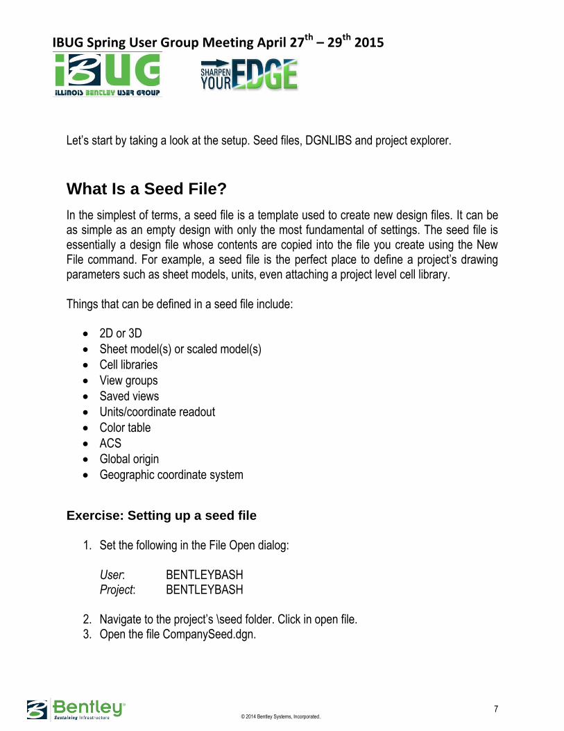
Type: Sheet Name: Master Sheet Description: 2D ANSI D Plot Annotation: Full Size 1=1 LS Scale: Global Line Style Scale Update Fields Automatically is checked on. Sheet Name: A-1 Sheet Number: 1 Display Sheet Boundary is checked on Border Attachment will be set later remind me Size: ANSI D Can be placed as cell is checked off Create a View Group is check on
4. Click OK. The Full Size Plot Sheet ANSI D sheet model opens and is listed in the Models dialog. Since we are in a 3D File the sheet model opens up 4 views. Close down all views except view 1 and maximize the view.
Exercise: Reference a border file
1. Continuing in CompanySeed.dgn, in the Reference File dialog, click Attach Reference. .
2. In attach reference File dialog, navigate to \Desktop\BENTLEYBASH\Borders\ANSI and select the file D-border.dgn.
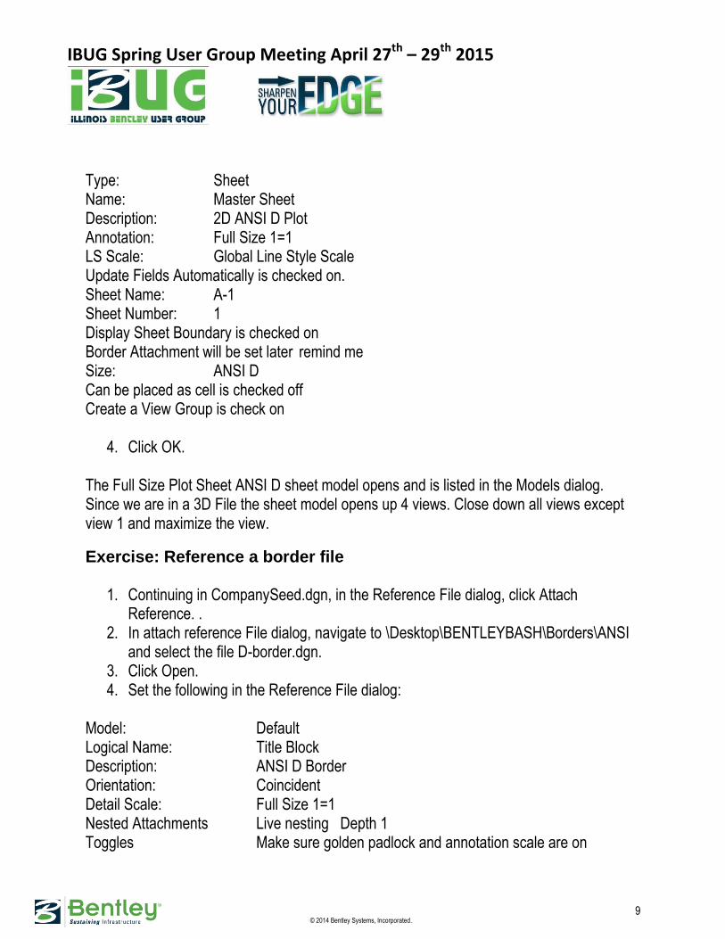
3. Click Open. 4. Set the following in the Reference File dialog:
Model: Default Logical Name: Title Block Description: ANSI D Border Orientation: Coincident Detail Scale: Full Size 1=1 Nested Attachments Live nesting Depth 1 Toggles Make sure golden padlock and annotation scale are on
IBUG Spring User Group Meeting April 27th – 29th 2015
10 © 2014 Bentley Systems, Incorporated.
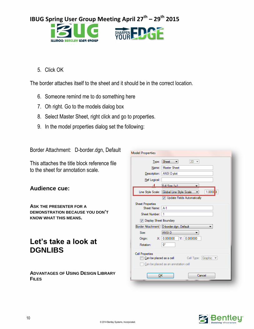
5. Click OK
The border attaches itself to the sheet and it should be in the correct location.
6. Someone remind me to do something here
7. Oh right. Go to the models dialog box
8. Select Master Sheet, right click and go to properties.
9. In the model properties dialog set the following:
Border Attachment: D-border.dgn, Default This attaches the title block reference file to the sheet for annotation scale.
Audience cue:
ASK THE PRESENTER FOR A
DEMONSTRATION BECAUSE YOU DON’T
KNOW WHAT THIS MEANS.
Let’s take a look at DGNLIBS
ADVANTAGES OF USING DESIGN LIBRARY
FILES
IBUG Spring User Group Meeting April 27th – 29th 2015
11 © 2014 Bentley Systems, Incorporated.
A design library is similar in function to a cell library. Users attach a cell library, select an active cell and place it in the design. Now the cell definition exists in two places, the cell library and in the design. It is possible for the local cell definition to change (in color, scale, etc.) from the cell library definition. To help users correct any discrepancies, there is an Update Cell tool. Like a cell library, the design library is the single source of user resources that is shared by all users. When a user chooses an active level from a DGN library and places an element on that level, then that level definition is written to the active file. With the read-only setting enabled for a DGN library, its function is also similar to a reference. You can see and use the contents, but not alter them. In addition to promoting the sharing of data and standards, DGN libraries provide other advantages. The main reason we use DGNLIBS to distribute standards rather than use the seed files is the difference between dynamic data and static data. A seed file contains static data, that means when a user creates a new file using a seed file the information in the seed file is copied to the new file and there is no link back to the seed file. If there is more information added to the seed file after the fact every new file created will get the information but all files that have already been created will not see that information. The new information will have to be physically added to the existing project files. A DGNLIB contains dynamic data, consider it a reference file. If your project files point to the DGNLIBS and more information is added to them it automatically shows in all of the project files.
Tour of a Typical Design Library File The best way to understand what the DGN library adds to the management of your operation is to inspect such a file. Following is a list of what resources you can store in a DGN library. Level Definitions and Level Filters
Text Styles
Dimension Styles
Detailing Symbol Styles

IBUG Spring User Group Meeting April 27th – 29th 2015
12 © 2014 Bentley Systems, Incorporated.
Multi-Line Styles
Display Styles
Cell definitions
User Interface customizations such as tools, menus, etc.
Project Explorer link sets
Color Books
Custom Line Styles
Standards Checker information
Element Templates
Render Setups
Clash Detection Settings
The next few exercises involve analyzing the content of an existing design library file. You will see how the level structure is set up, examine dimension and text styles and see how other definitions are handled. You can organize DGN libraries either as a single collection of all definitions or you can have several separate DGN libraries, each containing only one type of definition. MicroStation’s delivered \Examples\General project has just one DGN library that contains many types of definitions.
IBUG Spring User Group Meeting April 27th – 29th 2015
13 © 2014 Bentley Systems, Incorporated.
Exercise: Exploring a design library file
1. Set the following in the File Open dialog: User: BENTLEYBASH Project: BENTLEYBASH
2. Move up one level to the \dgnlib folder. 3. Open Architectural-Levels.dgnlib. 4. Open Level Manager by selecting Settings > Level > Manager, or click the Level
Manager tool in the Primary Tools toolbox.This design file appears empty but it contains several level definitions, each with its own unique override symbology.
5. In the Level Manager, set Symbology to Overrides. A different set of level definitions appears for each level definition.
6. Close the Level Manager. 7. Close the Level.dgnlib 8. Open the Text and Dimension Styles.dgnlib 9. Open the Dimension Settings dialog by selecting Element > Dimension Styles. You
see the styles present in this file, as well as those in any other mapped DGN libraries.
10. Select the dimension style named Notes Arrow. As its name implies, Notes Arrow is a style created for annotating details, using an arrow on the end of the leader line.
11. Select the Text tab and verify that the Text Style is Notes. 12. Close the Dimension Styles dialog. 13. Open the Text Styles dialog by selecting Element > Text Styles and note the styles
that are present. 14. Close the Text Styles dialog.
IBUG Spring User Group Meeting April 27th – 29th 2015
14 © 2014 Bentley Systems, Incorporated.
More possible DGN library file settings
PROJECT EXPLORER OVERVIEW
Project Explorer is a tool for insulating users from worrying about the location of files, models, or supporting documents. When project data is organized using Project Explorer, it does not matter to users where files, models, or supporting documents are actually located.
LINK SETS
Links to a project's data are stored in a link set. If link sets exist in the open DGN file or in the configured DGN libraries, a link set appears in the Project Explorer dialog when you open it. The default link set is the one that you were viewing most recently. If you have switched to a different DGN library, the first link set in that DGN library appears. The active link set's name appears in the drop-down list box and its links appear below its name. The links may be in folders, which you open and close by clicking the plus and minus signs to the left of the folders. Link sets come from one of three sources:
Configured Libraries: The links sets in all of the files specified by the MS_DGNLIBLIST configuration variable. If Configured Libraries is the source of your link set, you will be unable to modify the link set at this point. You will not be able to create or delete folders or links. To modify a link set from the Configured Libraries, you must open the file containing the link set. The name of the file in which the link set is stored appears in the File column in the list box.
Active File: Displays the link sets stored in the open DGN file. If this is the source of your link set, you will be able to modify the link set, but you will be unable to use the Undo button to reverse any changes you make.
Selected File: Lets you select a particular DGN file and displays the link sets contained in that DGN file. Click the Browse icon to choose a file. If this is the source of your link set, you will be able to modify the link set, but you will be unable to use the Undo button to reverse any changes you make.

IBUG Spring User Group Meeting April 27th – 29th 2015
15 © 2014 Bentley Systems, Incorporated.
The recommended way to access your link sets is through your configured libraries. If you select Configured Libraries, you will be able to choose from all link sets stored in the location to which the MS_DGNLIBLIST configuration variable points. Link sets stored here are available to all users whose configuration variable points to this location.
OPENING LINKS
Following a link to a data resource in the active link set in the Project Explorer dialog is called opening the link. There are some prerequisites for opening links:
You must have access to the location in which the file or target is stored.
You must have installed on your computer an application that is capable of opening and displaying the file.
Exercise: Creating a link set
1. Set the following in the File Open dialog: User: BENTLEYBASH Project: BENTLEYBASH
2. Open \dgnlib\Linkset.dgnlib 3. Select File > Project Explorer. 4. In the Project Explorer dialog, click the Manage Link Sets (magnifying glass) icon. 5. In the Link Sets dialog, you see that Configured Libraries (MS_DGNLIBLIST) is the
link set source selected. Link sets are being read from mapped DGN Libraries. 6. In the Project Explorer dialog, select the My Project link set and note the various
folders.

IBUG Spring User Group Meeting April 27th – 29th 2015
16 © 2014 Bentley Systems, Incorporated.
Design models reside in the Designs folder, sheet models in the Sheets folder, and so on. All the items to work on the Building project are available. The folders themselves are configuration variable links, each of which reflects the resources in any files identified by configuration variables. The links within the folders are automatically created, a process called harvesting. The Active Directory link set, which resides in ustation.dgnlib, contains configuration variable links to each of the following types of resources: design models, Drawing Models, Sheet models, plan views, elevation views, section views, and detail views. Do not modify the Active Directory link set, but consider copying it to create the link set for a new project.
7. Expand the node (plus sign) next to Designs.The resources are harvested and you
will note that there is a list of the Design Models in your current project. 8. Try the same with sheets. 9. Click Previous Model to return to the sheet model. 10. In the Link Sets dialog, change the setting to active file. You will notice the icons
become live to create linksets. Let’s look at creating linksets.
Link Types Link sets can contain the following types of links.
File — link to either a file or, for some file types, instances of types of data within the file. For example, you can create links to models and saved views within DGN files.
Folder — to a physical folder containing DGN, DWG, and other files.
Key-in — to a key-in command. This would allow you to execute that key-in command by attaching it an element or by right clicking on it and selecting Open.
URL — to a Uniform Resource Locator, such as the address of a Web page.
LinkSet —a link to another link set in the same workspace by selecting LinkSet Link from the Create Link options.
Configuration Variable — a Project Explorer folder containing links to resources pointed to by a configuration variable.

IBUG Spring User Group Meeting April 27th – 29th 2015
17 © 2014 Bentley Systems, Incorporated.
FOLDER LINKS
Folders can be dragged from Windows Explorer and dropped in the Project Explorer dialog or created via the PROJECT CREATE LINK FOLDER [folder-path] keyin. Multiple folder paths can be specified via this key-in. If you create a link to a folder, in the Project Explorer dialog, you will see the name of the folder in black, indicating you can copy or delete the folder and all the files and sub-folders within the folders. The files and sub-folders under the folder cannot be moved or deleted independently. Right click the linked folder in Project Explorer and select Open from the pop-up menu to open Windows Explorer at the location of the linked folder.
Exercise: Link to a physical folder 1. Select File > Open, move up two levels, and open \dgnlib\Linksets.dgnlib. 2. In the Project Explorer dialog, click the Manage Link Sets icon. 3. In the Link Sets dialog, set the link set option to Active File. 4. Create a new link sets named My Project 5. In the Project Explorer dialog, click New Folder 4 times. 6. Change the names to Cells, Documents, Web Sites and Project Files.. 7. Select the folder, click the arrow next to the Create Link icon, and select Folder Link
from the menu. 8. Navigate to ...\Desktop\ BENTLEYBASH\, select the \cell folder, and then click OK. 9. In the Project Explorer dialog, expand the Cells folder and then Civil.cel. You can
right click to open the models and edit their contents directly.
URL LINKS
You can create links which, when opened, send URL requests. A URL link can specify a Web page (http://), secure Web page (https://), or email address (mailto:). Select URL Link in the Create Link drop-down menu to create a URL link.

IBUG Spring User Group Meeting April 27th – 29th 2015
18 © 2014 Bentley Systems, Incorporated.
CONFIGURATION VARIABLE LINKS
You may need to create link sets containing folders that show key resources in a project. You should organize in folders by discipline, or using a relevant naming scheme to make configuration variables easier to use. One way to define the link set folders is to first set up a configuration variable to identify each discipline-specific part of the project directory structure. Any configuration variable that identifies files or directories can be used to define a configuration variable link. If the configuration variable identifies a directory, then all files in the directory and its subdirectories are searched. The configuration variable can also identify a single file or a regular expression. Create configuration variables to identify subsets of files that you want to harvest. Then create a Configuration Variable Link in the link set to reflect the resources in the files identified by each configuration variable. Each Configuration Variable Link identifies a configuration variable and specifies the type of resource to harvest from the files.
For a predefined variable, the definition of the selected variable appears in the Variable Name text box, and the default variable name appears in the Name text box. The filter expression identifies the type of resources to find within those files: {Model:Sheet} finds sheet
models or {Model:Design} finds design models.
The configuration variable identifies the set of files to be searched; $(MS_DEF) or $(MS_RFDIR).

IBUG Spring User Group Meeting April 27th – 29th 2015
19 © 2014 Bentley Systems, Incorporated.
For custom variable, key-in the variable name and definition. MicroStation generates the contents of the folder by searching for specified resources within a set of files. When resources are changed these folders can be refreshed to reflect the changes. A folder can only show one type of resource. To track more than one resource, create a separate folder for each type of resource.
Exercise: Create configuration variable links to the project’s Design and
Sheet views:
1. Returning to MicroStation and continuing in Linksets.dgnlib, with the My Project link set open in the Project Explorer dialog, highlight the Project Files folder, click Create Link and select Configuration Variable Link.
2. In the Create Configuration Variable Link dialog, set Variable to the pre-defined Design link.
3. Set the following: Name: Designs Variable Name: Designs (Model:Design)$(MS_DEF)
4. Do The same for Sheets, Views, Plans, Elevations, Sections and Details
Note: the other pre-defined variables in the list like DGNLIBS, Reference Files, Cell Library List and Custom.
Audience cue: GO AHEAD AND ASK ME ABOUT CUSTOM…..I DARE YA. Create a custom Variable name it Documents and set the variable to $(Docs) We are done with setup lets create a new drawing and start to gather our data.

IBUG Spring User Group Meeting April 27th – 29th 2015
20 © 2014 Bentley Systems, Incorporated.
Creating a MicroStation design file
To work in MicroStation you must either open an existing design file or create a new one. In the next exercise, you will create a MicroStation design file and give it a name before opening it. You will use the File Open dialog to create the file, but you can create a file from inside MicroStation by selecting File > New.
Exercise: Creating a new file
1. Click the New file icon at the top of the File Open dialog. 2. Type BSI300-9-Design Composition.dgn in the File name field of the New Design
File dialog. Do not press Enter yet. Doing so is the same as clicking OK or Save, which will finish the creation process and close the dialog you are using.
3. Observe the Save as type field. It is set to MicroStation DGN Files. This field is used to select the desired file type. The correct extension will be appended to the file name automatically.
4. Observe the Seed field, and then click the Browse button. It shows the path to the seed file that will be used. Other delivered seed files are in the folder. Select CompanySeed.dgn and click Open.
5. Click Save. The new file name, BSI300-9-Design Composition.dgn, appears in the File Open dialog.
Check to make sure that we have a Design Model and a Sheet Model. Open the model dialog box and make a copy of the Master Sheet and call it Floor Plan.
1. Right click on the Master Sheet 2. Select copy model 3. Rename it to Floor Plan 4. After you create the new sheet you can go into model properties and change the
sheet name and sheet number if you like.

IBUG Spring User Group Meeting April 27th – 29th 2015
21 © 2014 Bentley Systems, Incorporated.
Time to gather your Data
ATTACHING REFERENCES
Exercise: Select a file to attach 1. Open the model named Default. 2. Select the References tool from the Primary Tools toolbox. 3. In the References dialog, click Attach Reference. 4. In the Attach Reference dialog, select BSI300I-9-Structural.dgn.
Do not click Open yet. Examine the dialog.The default attachment method is Interactive. With this method, additional settings are set in the Reference Attachment Settings dialog. The attachment Method option menu on the right side of the dialog lets you select the method.
When you use the other attachment methods the Reference Attachment Settings dialog does not appear. The default attachment settings, or the attachment settings used for the last reference attached, are used instead. Once a method is selected, it remains in effect until it is changed.

IBUG Spring User Group Meeting April 27th – 29th 2015
22 © 2014 Bentley Systems, Incorporated.
The Save Relative Path check box in the Attach Reference dialog is important. A reference attachment that identifies the location of the file in which an attached file resides by its full, or absolute, path is not portable across directories, projects and networked systems. If the attached file is not found in that exact location, the attachment will be missing. The best way to ensure portability when attaching references is to enable Save Relative Path. This causes the relative path to the file to be saved as attachment data in the DGN file so the file can be more easily located.
ATTACHMENT SETTINGS
The first option in the Attachment Settings dialog is the model you want to attach.
Since the same model can be attached many times, the Logical Name field helps you to distinguish between them.
Orientation sets the view of the model that you will see. Coincident, the default, aligns the references with regard to design plane coordinates of the file to which you are attaching the reference. Coincident World aligns the references with the active model with regard to both Global Origin and design plane coordinates. You can also choose to attach a particular saved view or named fence if these are present.
Scale (Master:Ref) sets the ratio of the master units in the active file to the master units in the attached model. Use this if the reference elements need to be scaled. For example, 2 to 1 would make the referenced elements twice as large as elements in the master.
Exercise: Attach the Structural Composite model 1. Continuing in the Default model, set the following attachment settings in the
Reference Attachment Settings dialog: Model: Structural Composite Logical Name: Structural Orientation: Coincident Detail Scale: Full Size Nested Attach: No Nesting Depth: 0 Turn on the toggles Display, Snap, Locate, Treat Attachment as element, True Scale, Line Style Scale, Display raster, Use Lights, Plot as 3D PDF, Use annotation scale.

IBUG Spring User Group Meeting April 27th – 29th 2015
23 © 2014 Bentley Systems, Incorporated.
2. Click OK.
You now see the elements that are in the Structural Composite model. Switch your view to Isometric and do a fit view. Do the same for the other Three Architectural Drawings Starting with the drawing number BSI300. You should attach the interior, Shell and Core. Now we will use Display Styles and Dynamic Views to get the information we need out of our 3D Model.
Dynamic Views The term dynamic views refers to a method of composing drawings that is a new approach to managing projects. Dynamic views can help you to: Automate drawing creation
Keep MicroStation files up to date by:
Creating responsive drawings Connecting Saved Views to models Eliminate errors in design and documentation
Communicate design intent through models and drawings
Manage changes across MicroStation files
DYNAMIC VIEWS OVERVIEW
Dynamic views is a general name that encompasses several related technologies which share the goal of making model analysis and documentation interactive and intuitive. One of these technologies allows clipping of models and section graphics generation on the fly. Section views, detail views, and elevation views are types of dynamic views. Through the
IBUG Spring User Group Meeting April 27th – 29th 2015
24 © 2014 Bentley Systems, Incorporated.
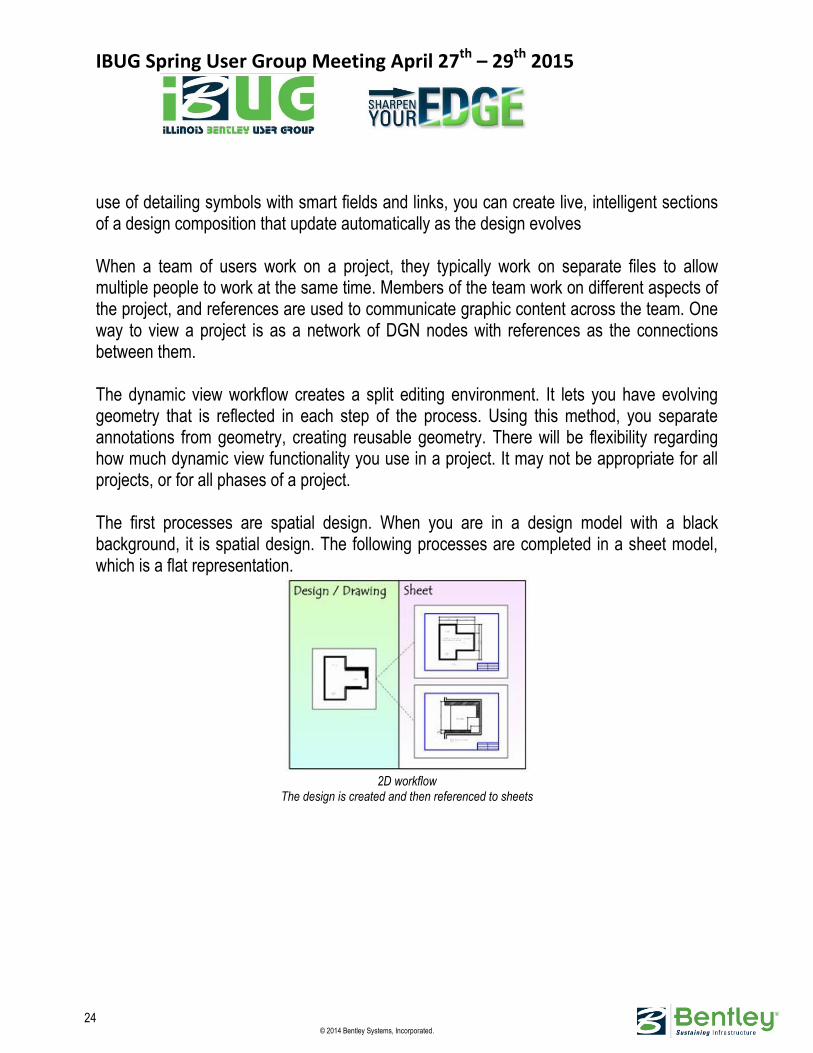
use of detailing symbols with smart fields and links, you can create live, intelligent sections of a design composition that update automatically as the design evolves When a team of users work on a project, they typically work on separate files to allow multiple people to work at the same time. Members of the team work on different aspects of the project, and references are used to communicate graphic content across the team. One way to view a project is as a network of DGN nodes with references as the connections between them. The dynamic view workflow creates a split editing environment. It lets you have evolving geometry that is reflected in each step of the process. Using this method, you separate annotations from geometry, creating reusable geometry. There will be flexibility regarding how much dynamic view functionality you use in a project. It may not be appropriate for all projects, or for all phases of a project. The first processes are spatial design. When you are in a design model with a black background, it is spatial design. The following processes are completed in a sheet model, which is a flat representation.
2D workflow
The design is created and then referenced to sheets
IBUG Spring User Group Meeting April 27th – 29th 2015
25 © 2014 Bentley Systems, Incorporated.
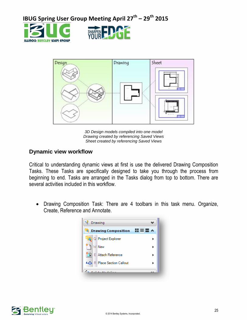
3D Design models compiled into one model Drawing created by referencing Saved Views Sheet created by referencing Saved Views
Dynamic view workflow Critical to understanding dynamic views at first is use the delivered Drawing Composition Tasks. These Tasks are specifically designed to take you through the process from beginning to end. Tasks are arranged in the Tasks dialog from top to bottom. There are several activities included in this workflow.
Drawing Composition Task: There are 4 toolbars in this task menu. Organize, Create, Reference and Annotate.
IBUG Spring User Group Meeting April 27th – 29th 2015
26 © 2014 Bentley Systems, Incorporated.
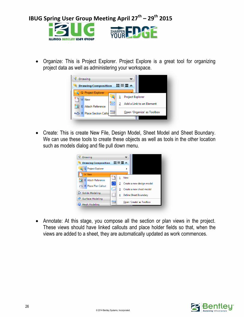
Organize: This is Project Explorer. Project Explore is a great tool for organizing project data as well as administering your workspace.
Create: This is create New File, Design Model, Sheet Model and Sheet Boundary.
We can use these tools to create these objects as well as tools in the other location such as models dialog and file pull down menu.
Annotate: At this stage, you compose all the section or plan views in the project.
These views should have linked callouts and place holder fields so that, when the views are added to a sheet, they are automatically updated as work commences.
IBUG Spring User Group Meeting April 27th – 29th 2015
27 © 2014 Bentley Systems, Incorporated.
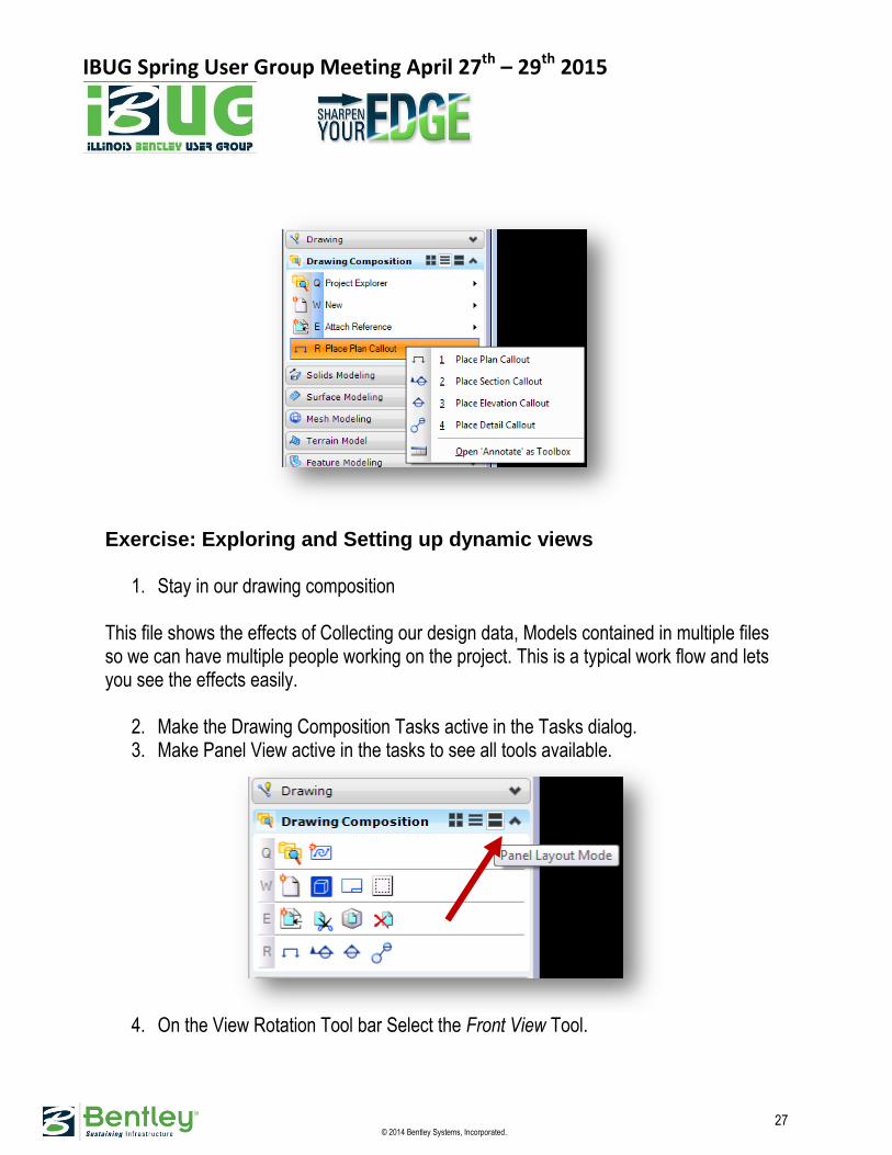
Exercise: Exploring and Setting up dynamic views
1. Stay in our drawing composition This file shows the effects of Collecting our design data, Models contained in multiple files so we can have multiple people working on the project. This is a typical work flow and lets you see the effects easily.
2. Make the Drawing Composition Tasks active in the Tasks dialog. 3. Make Panel View active in the tasks to see all tools available.
4. On the View Rotation Tool bar Select the Front View Tool.
IBUG Spring User Group Meeting April 27th – 29th 2015
28 © 2014 Bentley Systems, Incorporated.
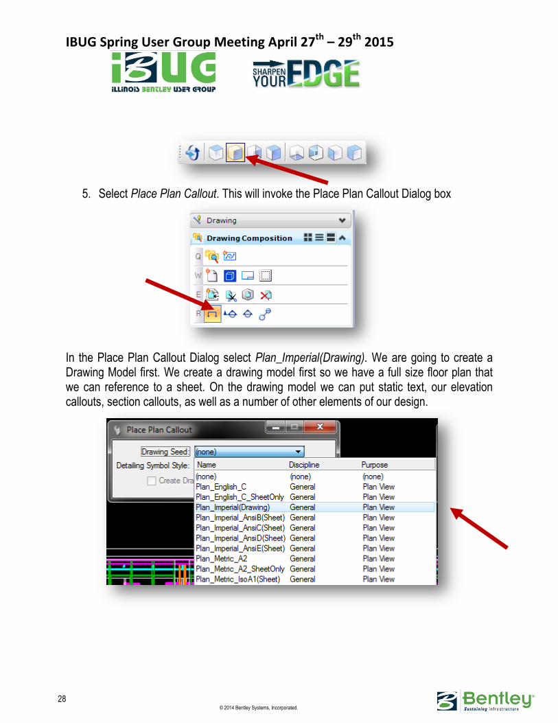
5. Select Place Plan Callout. This will invoke the Place Plan Callout Dialog box
In the Place Plan Callout Dialog select Plan_Imperial(Drawing). We are going to create a Drawing Model first. We create a drawing model first so we have a full size floor plan that we can reference to a sheet. On the drawing model we can put static text, our elevation callouts, section callouts, as well as a number of other elements of our design.

IBUG Spring User Group Meeting April 27th – 29th 2015
29 © 2014 Bentley Systems, Incorporated.
6. On the view of the front elevation place a clip line just below the door headers on the first floor and pull the clip line down to the bottom of the elevation. This box sets a clip volume depth for the floor plan and displays the Create Drawing dialog box.
NOTE: The key to cutting this floor plan and creating our documents is to get it to look just like we want it to look on the sheet.
IBUG Spring User Group Meeting April 27th – 29th 2015
30 © 2014 Bentley Systems, Incorporated.
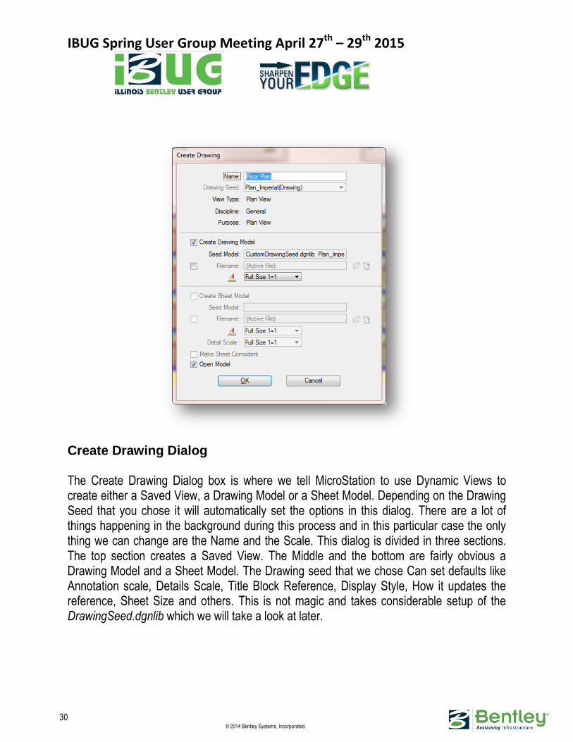
Create Drawing Dialog The Create Drawing Dialog box is where we tell MicroStation to use Dynamic Views to create either a Saved View, a Drawing Model or a Sheet Model. Depending on the Drawing Seed that you chose it will automatically set the options in this dialog. There are a lot of things happening in the background during this process and in this particular case the only thing we can change are the Name and the Scale. This dialog is divided in three sections. The top section creates a Saved View. The Middle and the bottom are fairly obvious a Drawing Model and a Sheet Model. The Drawing seed that we chose Can set defaults like Annotation scale, Details Scale, Title Block Reference, Display Style, How it updates the reference, Sheet Size and others. This is not magic and takes considerable setup of the DrawingSeed.dgnlib which we will take a look at later.

IBUG Spring User Group Meeting April 27th – 29th 2015
31 © 2014 Bentley Systems, Incorporated.
Continuing with our Project, In the Create Drawing Dialog
1. change the Name to Floor Plan 2. The Create Drawing Model box should be checked 3. The Seed Model should already be filled out for us. That is set in the dgnlib. 4. Annotation Scale set to Full Size 1=1 (Drawing Models should almost always be
1=1) 5. Create Sheet Model should be unchecked and grayed out. 6. The Open Model box should be checked. 7. Click OK
The drawing model will open with the clip volume you just set and the default display style set in the dgnlib. Also in the view you will see an Icon on the screen called a marker. If you hover over the marker with your cursor you will see a mini toolbar. You can use the mini toolbar to navigate your project or create another Dynamic View.
Just a Reminder: Remember to get this Drawing Model looking exactly how you want it to look on your sheet. It will make less work for us in the future. The look of the Floor Plan Drawing is controlled by a Display Style. This is a saved view Referenced to the drawing and it’s 2D. The display style does not exist in the Drawing or Sheet model. Since we created this floor plan from our 3D model the clip volume and display style exists in the Design Model. If you have to make adjustments you have to do it in the 3D model and update the saved view. The changes will automatically reflect in the Drawing or Sheet.
From left to right: a plan, section, elevation, and detail marker.

IBUG Spring User Group Meeting April 27th – 29th 2015
32 © 2014 Bentley Systems, Incorporated.
DISPLAY STYLES
When a Display Style is created or an existing style is modified, enabling the Clip Volume box in the Display Style window will place the style as an additional option in the Clip
Volume Settings. Clicking on the magnifying glass will open the Display Styles dialog. Exercise: Setting up a Display Style We will use display styles to make this look how we want it to look on the sheet first a brief explaination of the clip volume
settings in the view attributes dialog box.

IBUG Spring User Group Meeting April 27th – 29th 2015
33 © 2014 Bentley Systems, Incorporated.
The clip volume setting are set in relation of the clip volume element that you see when you place the clip volume. You can see the extents of the clip volume as dashed lines. The cut plane is a dashed rectangle at the tip of the green arrow. Along with the green arrow you see a number of blue push pins, these all have relevance in the clip volume settings. Forward From the tip of the green arrow forward in the direction of the arrow Back From the tip of the green arrow back in the oposite direction of the arrow Cut The cutting plane at the tip of the green arrow. The dashed outline rectangle Outside Out side the blue push pins on the edge of the clip cube
In the View Attributes dialog box click on the list box of the Forward option and you should notice that the list in the box does not match the list in the display styles dialog box. That’s because not all of the display styles are set up to view in the clip volume settings. Lets make sure that all of these display style show up in views and clip volumes by checking both boxes under usage. Change your plan view to Isometric.
1. Set your forward display style to illustrated with shadows. 2. Set your cut to Plan_Cut and notice the changes to your view. 3. Turn on the display for back and set it to Clash Background. 4. Click on the front blue push pin and move it back to the middle of the building 5. Turn on the outside clip volume setting and it should come up with the outside
display style 6. Let put everything back to the way it was and set up our Floor Plan. 7. Move the blue pin back to where it was, Turn off the display for Back and Outside. 8. Lets switch our view from Isometric to top. 9. Now we have to make this look like a floor plan change forward to wireframe.
We need to get rid of the color so we have to create a display style that is close to wireframe and another that is close to Plan_Cut.
10. Open the Display Styles dialog by clicking on the magnifying glass next to Forward 11. Highlight Wireframe and select the copy icon at the top of the dialog box. 12. Rename copy of Wireframe to Wireframe Mono Plan 13. Do the same to Cut and rename it to Cut Mono Plan 14. Highlight Wireframe Mono Plan and change the Overrides Elrments settings to:
IBUG Spring User Group Meeting April 27th – 29th 2015
34 © 2014 Bentley Systems, Incorporated.
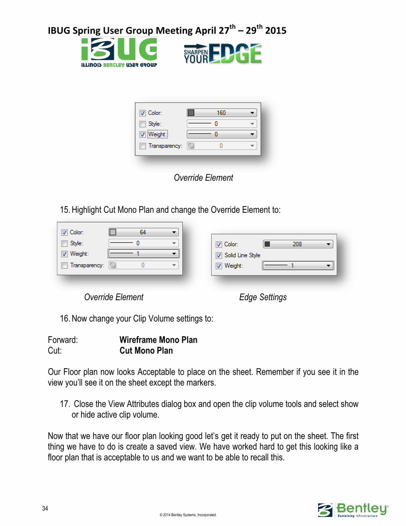
Override Element
15. Highlight Cut Mono Plan and change the Override Element to:
Override Element Edge Settings
16. Now change your Clip Volume settings to: Forward: Wireframe Mono Plan Cut: Cut Mono Plan Our Floor plan now looks Acceptable to place on the sheet. Remember if you see it in the view you’ll see it on the sheet except the markers.
17. Close the View Attributes dialog box and open the clip volume tools and select show or hide active clip volume.
Now that we have our floor plan looking good let’s get it ready to put on the sheet. The first thing we have to do is create a saved view. We have worked hard to get this looking like a floor plan that is acceptable to us and we want to be able to recall this.
IBUG Spring User Group Meeting April 27th – 29th 2015
35 © 2014 Bentley Systems, Incorporated.
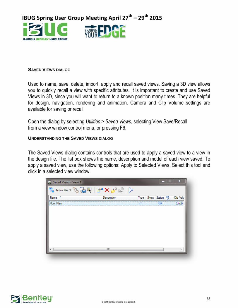
SAVED VIEWS DIALOG
Used to name, save, delete, import, apply and recall saved views. Saving a 3D view allows you to quickly recall a view with specific attributes. It is important to create and use Saved Views in 3D, since you will want to return to a known position many times. They are helpful for design, navigation, rendering and animation. Camera and Clip Volume settings are available for saving or recall. Open the dialog by selecting Utilities > Saved Views, selecting View Save/Recall from a view window control menu, or pressing F6.
UNDERSTANDING THE SAVED VIEWS DIALOG
The Saved Views dialog contains controls that are used to apply a saved view to a view in the design file. The list box shows the name, description and model of each view saved. To apply a saved view, use the following options: Apply to Selected Views. Select this tool and click in a selected view window.
IBUG Spring User Group Meeting April 27th – 29th 2015
36 © 2014 Bentley Systems, Incorporated.
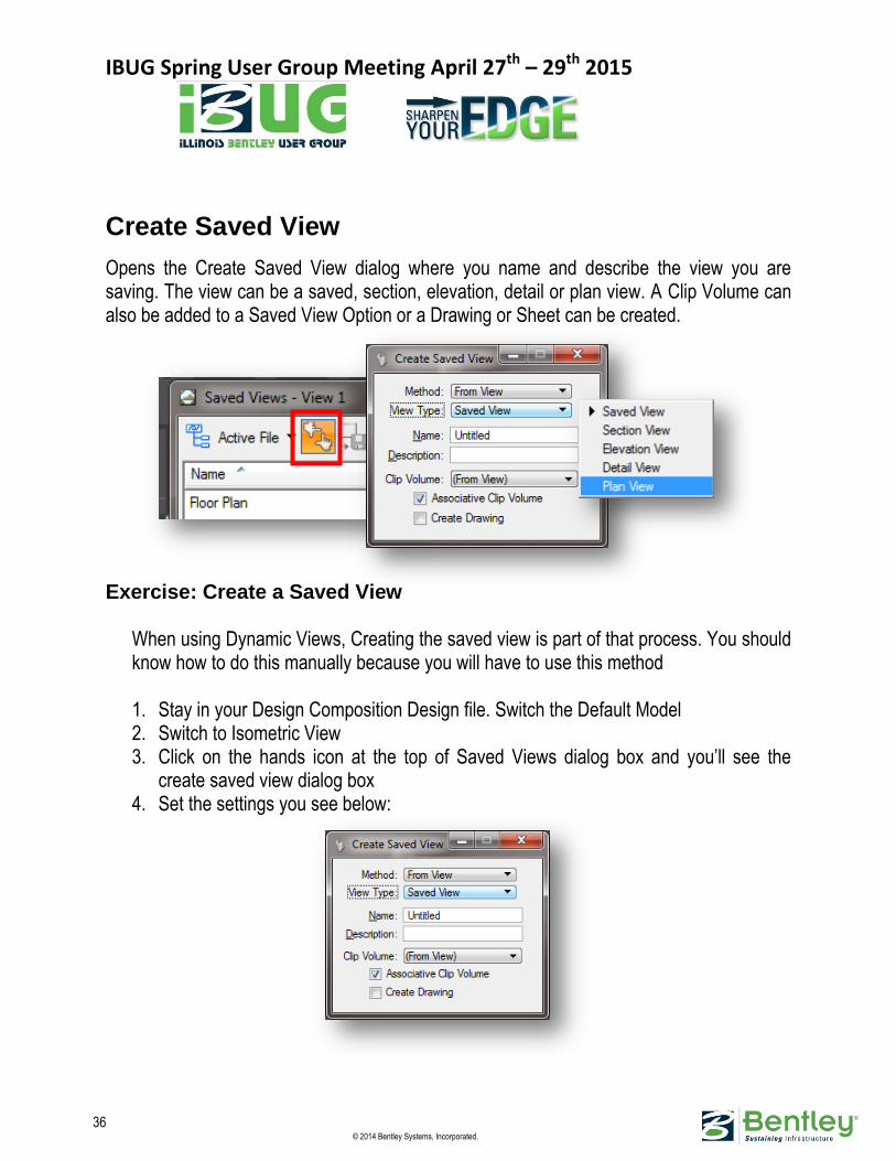
Create Saved View
Opens the Create Saved View dialog where you name and describe the view you are saving. The view can be a saved, section, elevation, detail or plan view. A Clip Volume can also be added to a Saved View Option or a Drawing or Sheet can be created.
Exercise: Create a Saved View
When using Dynamic Views, Creating the saved view is part of that process. You should know how to do this manually because you will have to use this method 1. Stay in your Design Composition Design file. Switch the Default Model 2. Switch to Isometric View 3. Click on the hands icon at the top of Saved Views dialog box and you’ll see the
create saved view dialog box 4. Set the settings you see below:
IBUG Spring User Group Meeting April 27th – 29th 2015
37 © 2014 Bentley Systems, Incorporated.
5. Click in the View to accept. You’ll see the saved view show up in the saved views dialog.
The Important settings in this dialog box are View type, Associate Clip Volume and Create Drawing.
Audience cue:
Time for the audience to get involved ask me about the settings in this dialog box.. We are going to do one more saved view right now. Let’s do a saved view of our original Isometric wireframe.
1. Click on the Clip Volume tools and select the clear active clip volume tool. Data point in the view and return your view to isometric.
2. Do a fit view and click on the hands set the following settings: View Type: Saved View Name and Discription: Isometric Turn off Associative Clip Volume and Create Drawing
3. Data point in the view. 4. You should see the Iso View come up in the saved views dialog box.
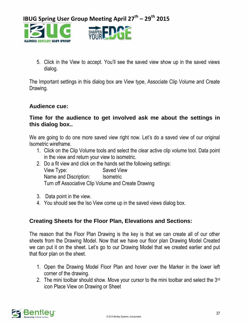
Creating Sheets for the Floor Plan, Elevations and Sections: The reason that the Floor Plan Drawing is the key is that we can create all of our other sheets from the Drawing Model. Now that we have our floor plan Drawing Model Created we can put it on the sheet. Let’s go to our Drawing Model that we created earlier and put that floor plan on the sheet.
1. Open the Drawing Model Floor Plan and hover over the Marker in the lower left corner of the drawing.
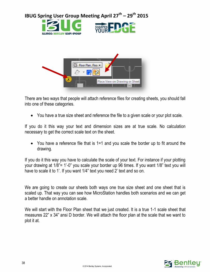
2. The mini toolbar should show. Move your cursor to the mini toolbar and select the 3rd icon Place View on Drawing or Sheet
IBUG Spring User Group Meeting April 27th – 29th 2015
38 © 2014 Bentley Systems, Incorporated.
There are two ways that people will attach reference files for creating sheets, you should fall into one of these categories.
You have a true size sheet and reference the file to a given scale or your plot scale. If you do it this way your text and dimension sizes are at true scale. No calculation necessary to get the correct scale text on the sheet.
You have a reference file that is 1=1 and you scale the border up to fit around the drawing.
If you do it this way you have to calculate the scale of your text. For instance if your plotting your drawing at 1/8”= 1’-0” you scale your border up 96 times. If you want 1/8” text you will have to scale it to 1’. If you want 1/4” text you need 2’ text and so on. We are going to create our sheets both ways one true size sheet and one sheet that is scaled up. That way you can see how MicroStation handles both scenarios and we can get a better handle on annotation scale. We will start with the Floor Plan sheet that we just created. It is a true 1-1 scale sheet that measures 22” x 34” ansi D border. We will attach the floor plan at the scale that we want to plot it at.
IBUG Spring User Group Meeting April 27th – 29th 2015
39 © 2014 Bentley Systems, Incorporated.
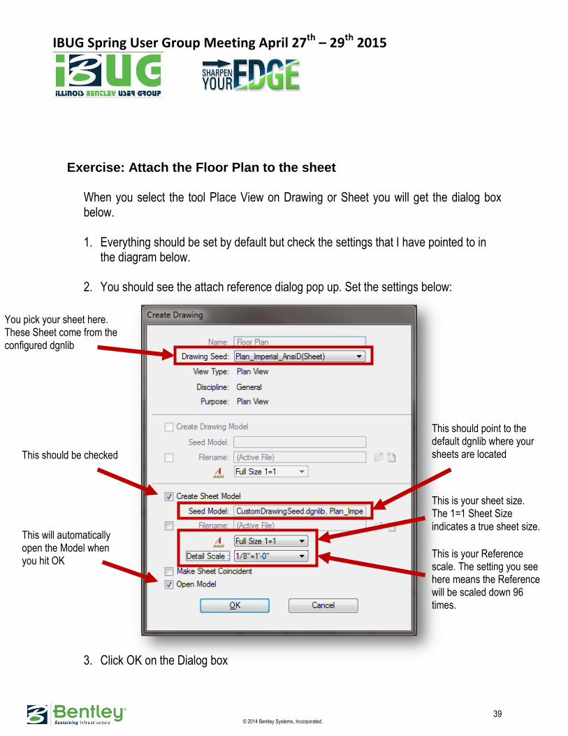
Exercise: Attach the Floor Plan to the sheet
When you select the tool Place View on Drawing or Sheet you will get the dialog box below. 1. Everything should be set by default but check the settings that I have pointed to in
the diagram below.
2. You should see the attach reference dialog pop up. Set the settings below:
3. Click OK on the Dialog box
This should point to the default dgnlib where your sheets are located
You pick your sheet here. These Sheet come from the configured dgnlib
This is your sheet size. The 1=1 Sheet Size indicates a true sheet size.
This is your Reference scale. The setting you see here means the Reference will be scaled down 96 times.
This should be checked
This will automatically open the Model when you hit OK
IBUG Spring User Group Meeting April 27th – 29th 2015
40 © 2014 Bentley Systems, Incorporated.
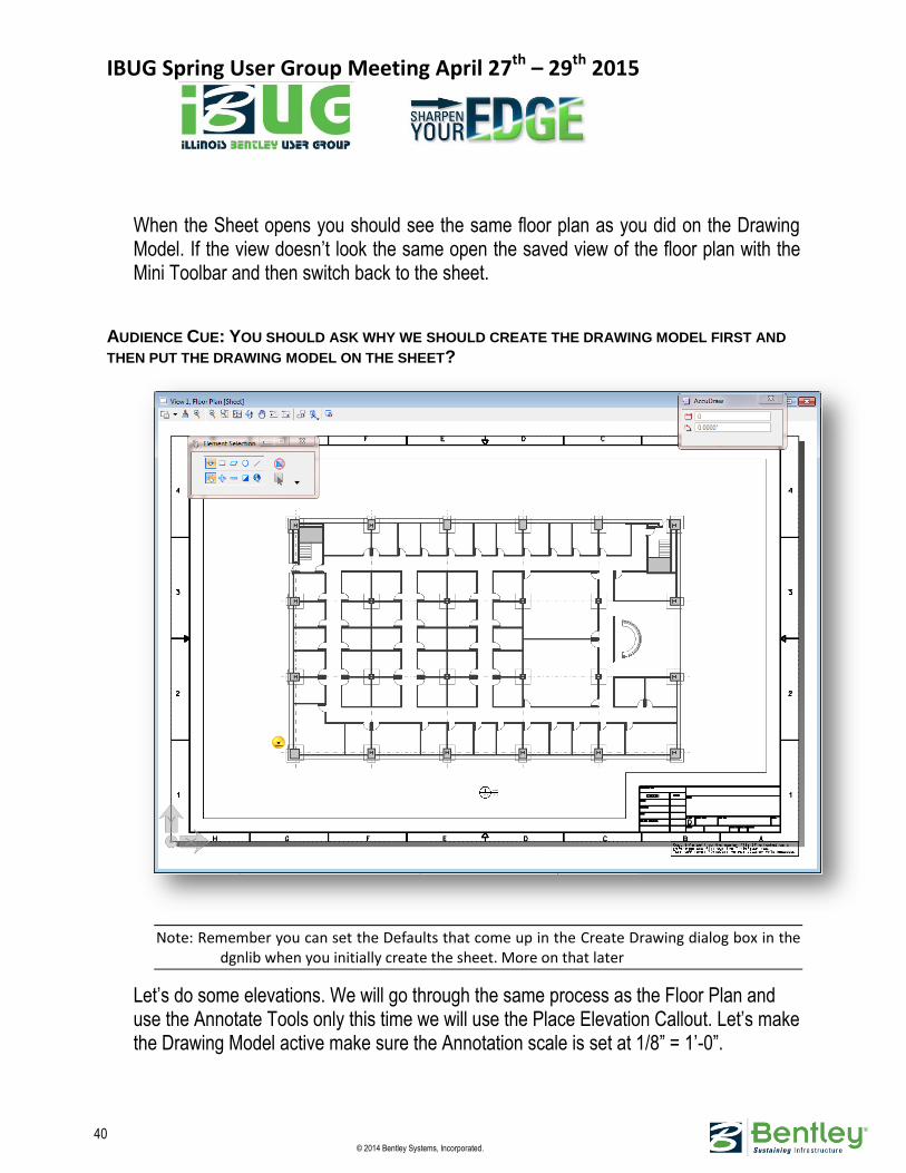
When the Sheet opens you should see the same floor plan as you did on the Drawing Model. If the view doesn’t look the same open the saved view of the floor plan with the Mini Toolbar and then switch back to the sheet.
AUDIENCE CUE: YOU SHOULD ASK WHY WE SHOULD CREATE THE DRAWING MODEL FIRST AND
THEN PUT THE DRAWING MODEL ON THE SHEET?
Note: Remember you can set the Defaults that come up in the Create Drawing dialog box in the dgnlib when you initially create the sheet. More on that later
Let’s do some elevations. We will go through the same process as the Floor Plan and use the Annotate Tools only this time we will use the Place Elevation Callout. Let’s make the Drawing Model active make sure the Annotation scale is set at 1/8” = 1’-0”.

IBUG Spring User Group Meeting April 27th – 29th 2015
41 © 2014 Bentley Systems, Incorporated.
1. You can place the Elevation Callout on the Drawing or the Sheet. I like to place them on the Drawing. Since the Drawing is referenced to the sheet the callouts will also show up on the sheet. Lets Place the Elevation callout in the front of the floor plan.
2. Enter a datapoint in front of the floor plan you will see the callout at your cursor. Move your cursor straight up making sure the callout is exactly perpendicular to the floor plan.
Notice the Sheet is automatically selected. It knows that you are creating an Elevation
Make sure you select height from Model not from View.
IBUG Spring User Group Meeting April 27th – 29th 2015
42 © 2014 Bentley Systems, Incorporated.
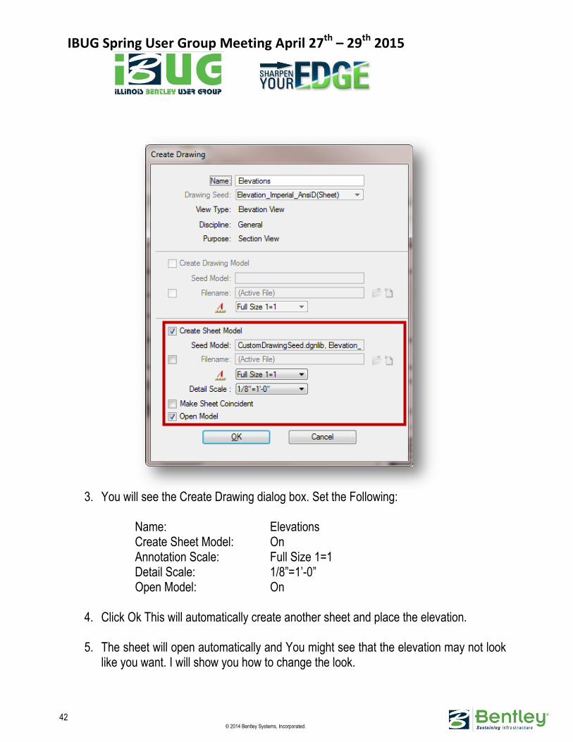
3. You will see the Create Drawing dialog box. Set the Following:
Name: Elevations Create Sheet Model: On Annotation Scale: Full Size 1=1 Detail Scale: 1/8”=1’-0” Open Model: On
4. Click Ok This will automatically create another sheet and place the elevation.
5. The sheet will open automatically and You might see that the elevation may not look
like you want. I will show you how to change the look.
IBUG Spring User Group Meeting April 27th – 29th 2015
43 © 2014 Bentley Systems, Incorporated.
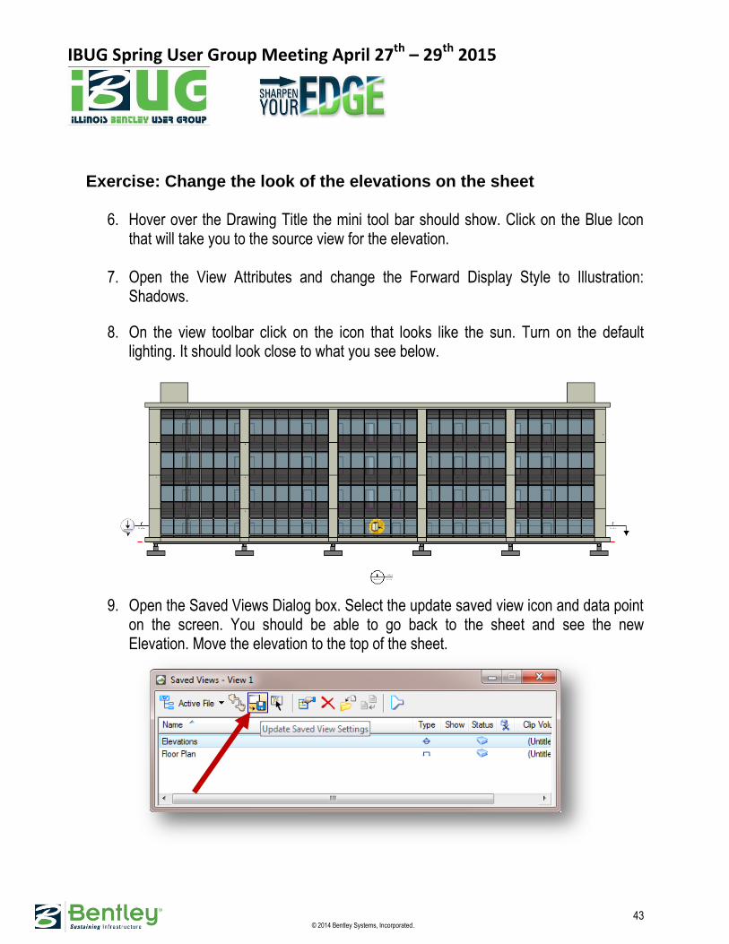
Exercise: Change the look of the elevations on the sheet 6. Hover over the Drawing Title the mini tool bar should show. Click on the Blue Icon
that will take you to the source view for the elevation.
7. Open the View Attributes and change the Forward Display Style to Illustration: Shadows.
8. On the view toolbar click on the icon that looks like the sun. Turn on the default lighting. It should look close to what you see below.
9. Open the Saved Views Dialog box. Select the update saved view icon and data point
on the screen. You should be able to go back to the sheet and see the new Elevation. Move the elevation to the top of the sheet.
IBUG Spring User Group Meeting April 27th – 29th 2015
44 © 2014 Bentley Systems, Incorporated.
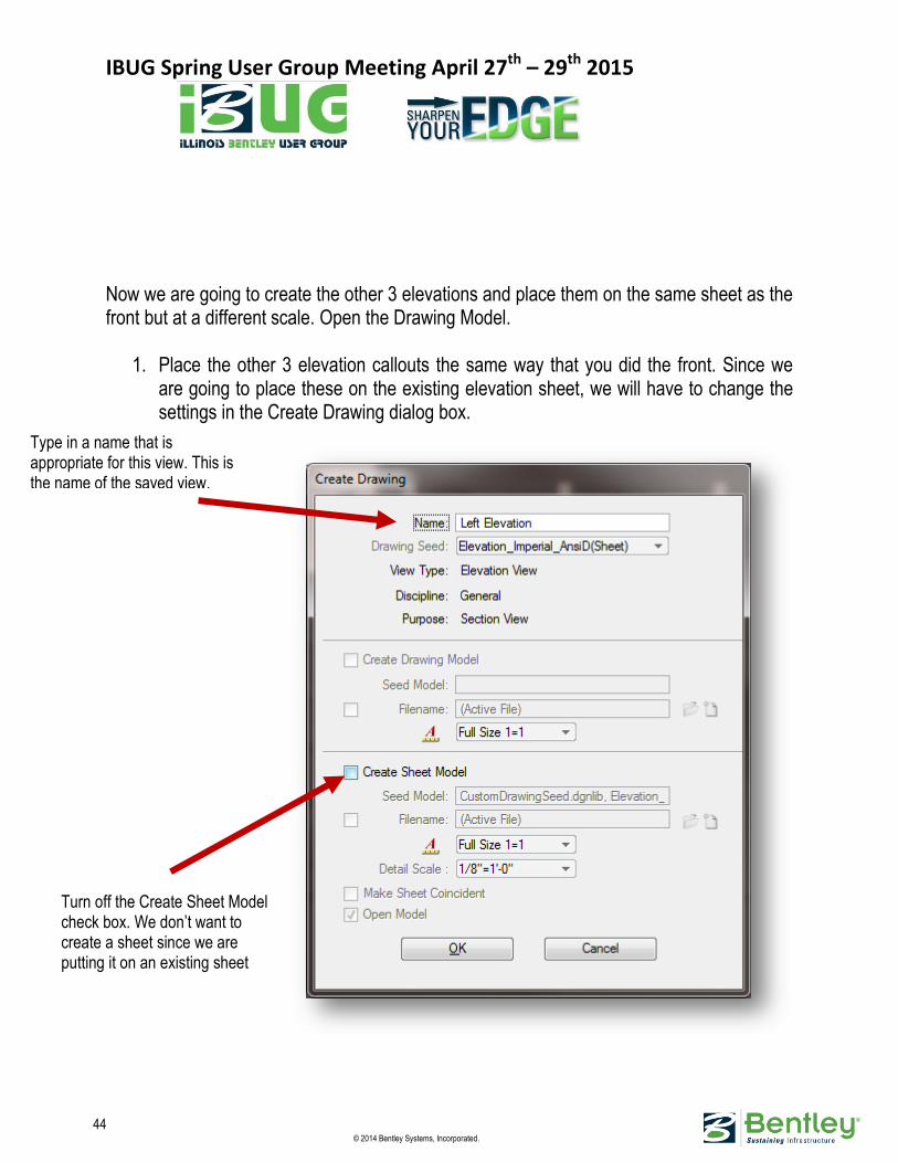
Now we are going to create the other 3 elevations and place them on the same sheet as the front but at a different scale. Open the Drawing Model.
1. Place the other 3 elevation callouts the same way that you did the front. Since we are going to place these on the existing elevation sheet, we will have to change the settings in the Create Drawing dialog box.
Type in a name that is appropriate for this view. This is the name of the saved view.
Turn off the Create Sheet Model check box. We don’t want to create a sheet since we are putting it on an existing sheet

IBUG Spring User Group Meeting April 27th – 29th 2015
45 © 2014 Bentley Systems, Incorporated.
2. Open the Elevations Sheet. 3. We can use the saved views Dialog and just drag and drop. The Saved View onto
the sheet. 4. Starting with the Left Elevation Highlight the View and drag and drop it on the sheet.
5. Attachment Method should be Interactive

IBUG Spring User Group Meeting April 27th – 29th 2015
46 © 2014 Bentley Systems, Incorporated.
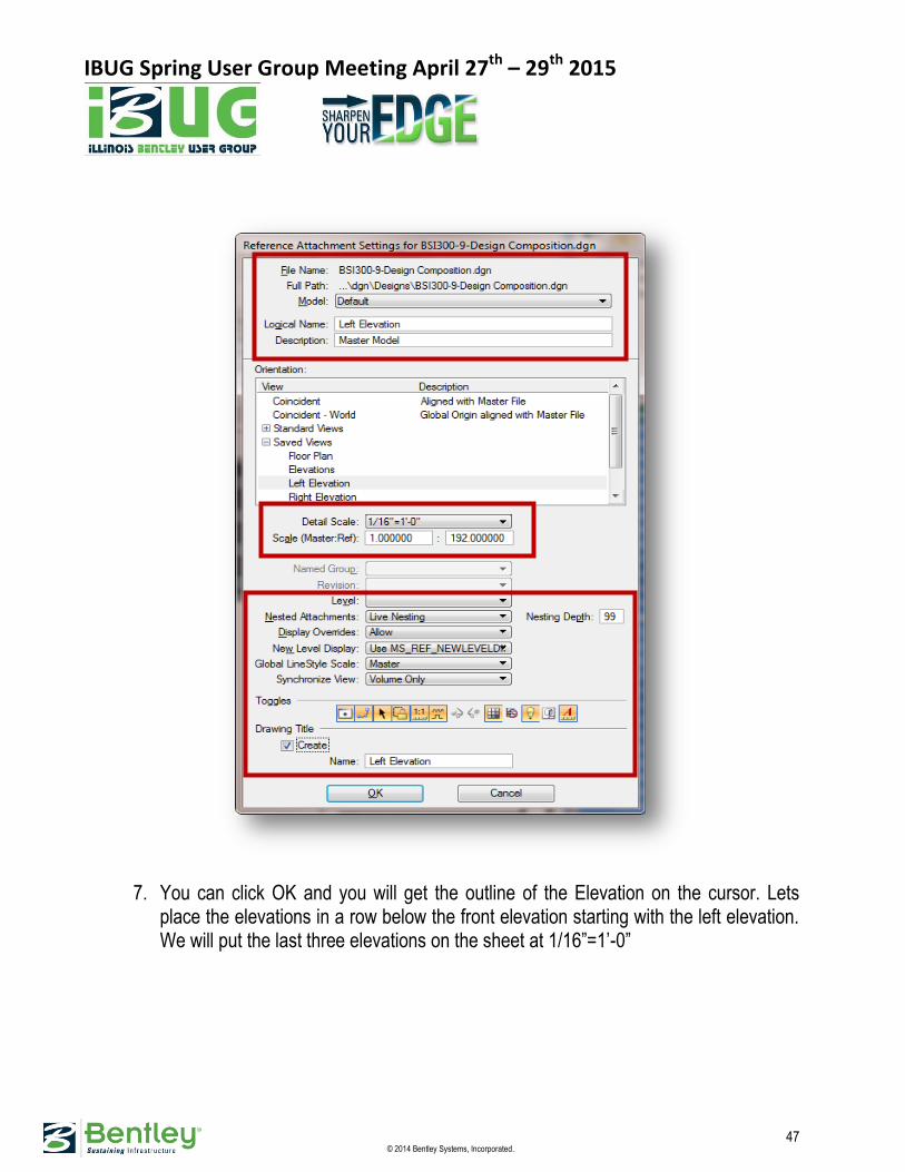
6. Check the Settings for attachment of the elevation
IBUG Spring User Group Meeting April 27th – 29th 2015
47 © 2014 Bentley Systems, Incorporated.
7. You can click OK and you will get the outline of the Elevation on the cursor. Lets place the elevations in a row below the front elevation starting with the left elevation. We will put the last three elevations on the sheet at 1/16”=1’-0”
IBUG Spring User Group Meeting April 27th – 29th 2015
48 © 2014 Bentley Systems, Incorporated.
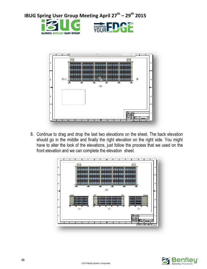
8. Continue to drag and drop the last two elevations on the sheet. The back elevation
should go in the middle and finally the right elevation on the right side. You might have to alter the look of the elevations, just follow the process that we used on the front elevation and we can complete the elevation sheet.
IBUG Spring User Group Meeting April 27th – 29th 2015
49 © 2014 Bentley Systems, Incorporated.
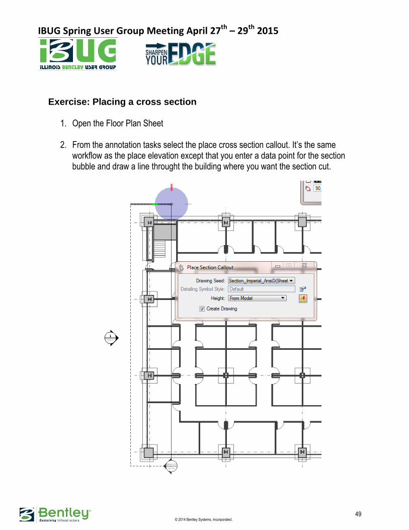
Exercise: Placing a cross section
1. Open the Floor Plan Sheet
2. From the annotation tasks select the place cross section callout. It’s the same workflow as the place elevation except that you enter a data point for the section bubble and draw a line throught the building where you want the section cut.

IBUG Spring User Group Meeting April 27th – 29th 2015
50 © 2014 Bentley Systems, Incorporated.
3. In the Create Drawing dialog, set the following settings:
4. Select OK and the section sheet will open. 5. I don’t like the look of this section so I want to change it just like we changed the
elevations.
AUDIENCE CUE: ASK ME WHAT ELSE WE CAN DO WITH CROSS SECTIONS
If we have some time we can create a detail sheet but right now let move on to printing the sheets we already have created. There is a cover sheet that is already in the project which is a separate file. You can go to Project Explorer and see the sheets we have created in the list. Again this information is automatically harvested through a configuration variable. You
IBUG Spring User Group Meeting April 27th – 29th 2015
51 © 2014 Bentley Systems, Incorporated.
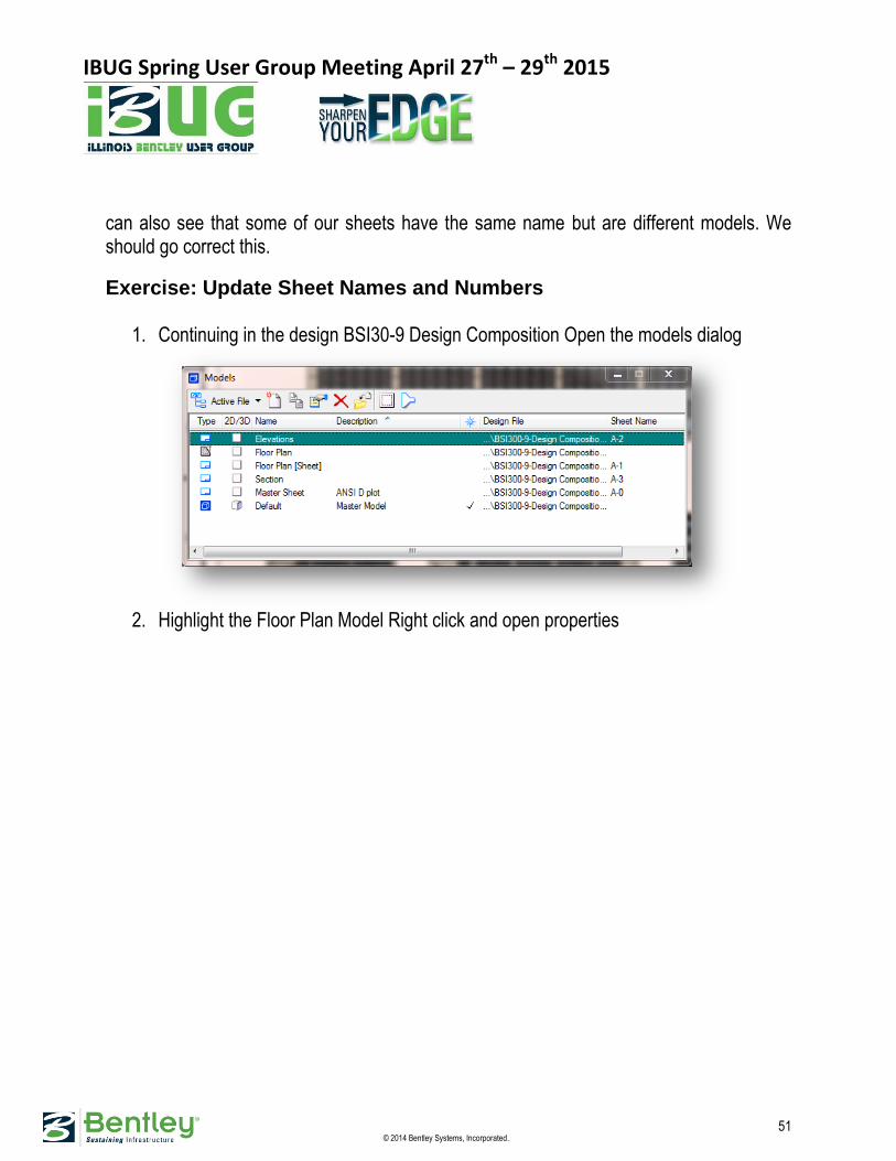
can also see that some of our sheets have the same name but are different models. We should go correct this.
Exercise: Update Sheet Names and Numbers
1. Continuing in the design BSI30-9 Design Composition Open the models dialog
2. Highlight the Floor Plan Model Right click and open properties
IBUG Spring User Group Meeting April 27th – 29th 2015
52 © 2014 Bentley Systems, Incorporated.
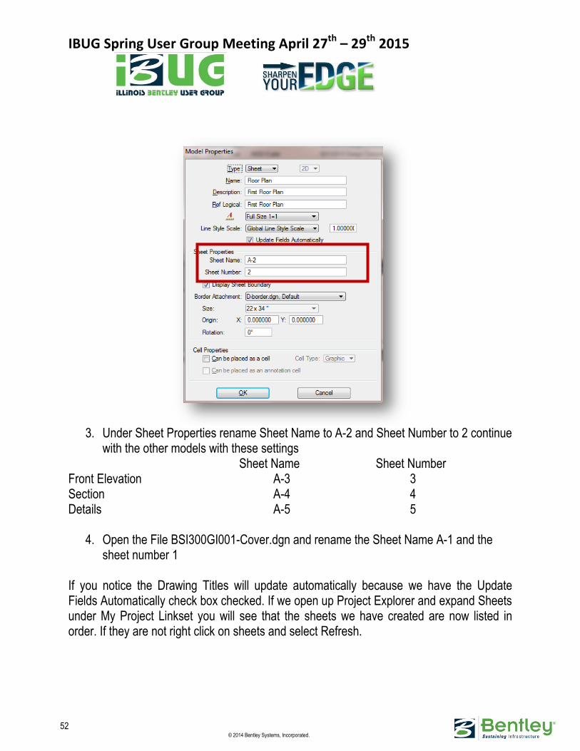
3. Under Sheet Properties rename Sheet Name to A-2 and Sheet Number to 2 continue
with the other models with these settings Sheet Name Sheet Number
Front Elevation A-3 3 Section A-4 4 Details A-5 5
4. Open the File BSI300GI001-Cover.dgn and rename the Sheet Name A-1 and the sheet number 1
If you notice the Drawing Titles will update automatically because we have the Update Fields Automatically check box checked. If we open up Project Explorer and expand Sheets under My Project Linkset you will see that the sheets we have created are now listed in order. If they are not right click on sheets and select Refresh.
IBUG Spring User Group Meeting April 27th – 29th 2015
53 © 2014 Bentley Systems, Incorporated.
Time to Setup Printing
PRINT ORGANIZER AND PROJECT EXPLORER
You can drag and drop DGN file, model, or saved view links from Project Explorer into Print Organizer. You can also right click these type items and select Print Organizer to create a new print set.
COMPOSING PRINT SETS
You can compose a print set file using Project Explorer and Print Organizer. File, model, or saved view links in Project Explorer can be added to a new or existing print set file. To compose a new print set file, right click a file, model, or saved view link and select Print Organizer from the pop-up menu. If Print Organizer already has a print set file open, you will be asked to save the changes for the existing print set file; otherwise, the Create Print Definitions dialog opens with the selected links displayed in the Input files list box. The Input files list box displays various objects using the following format: DGN file name, model name, saved view name. The Create Print Definitions dialog lets you specify print definition creation options to the objects in the Input files list box. You can specify a Print Style to apply a collection of print definition creation options, or you can click Manually Specified Options to open the Print Definition Creation Options dialog to specify print definition creation options.
Note: If the object in the Input files list box is a model name, the model selection method in a Print Style or in the Manually Specified Options is ignored. Also, if the object in the Input files list box is a saved view name, the model selection method and the view name in a Print Style or in the Manually Specified Options is ignored.
You can also drag and drop file, model, and saved view links into an existing print set file. You can create a link to a print set, or individual print definitions.
HOW TO COMPOSE A NEW PRINT SET FILE USING PROJECT EXPLORER AND PRINT ORGANIZER:
1. You should have Project Explorer open and the Sheets should be displayed.
Highlight all the sheet, Right click on the highlighted files and select Print Organizer.
IBUG Spring User Group Meeting April 27th – 29th 2015
54 © 2014 Bentley Systems, Incorporated.
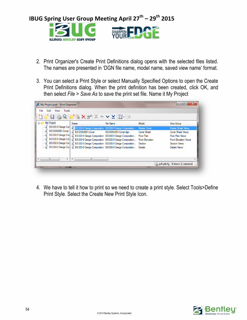
2. Print Organizer's Create Print Definitions dialog opens with the selected files listed. The names are presented in ‘DGN file name, model name, saved view name’ format.
3. You can select a Print Style or select Manually Specified Options to open the Create
Print Definitions dialog. When the print definition has been created, click OK, and then select File > Save As to save the print set file. Name it My Project
4. We have to tell it how to print so we need to create a print style. Select Tools>Define Print Style. Select the Create New Print Style Icon.

IBUG Spring User Group Meeting April 27th – 29th 2015
55 © 2014 Bentley Systems, Incorporated.
5. Select the printer tab first. Click on the magnifying glass and chose pdf.pltcfg 6. Select the Main tab and set the following settings
Print Area: Sheet Size and Scale Maximize Paper Size: ANSI D
7. Click on the disc to save your settings and rename the new print style ANSI D pdf 8. Select the copy button rename the copy to ANSI B pdf and change the sheet size to
ANSI B. Click on the disc to save the settings and close the dialog box.
9. The master sheet is blank so let’s delete that sheet. 10. We have to apply the print style and we want to print the cover sheet on ansi B but
all the others we want on ansi D
IBUG Spring User Group Meeting April 27th – 29th 2015
56 © 2014 Bentley Systems, Incorporated.
11. Highlight the cover sheet, select tools and apply print style. Select ansi B 12. Highlight all the other files and apply the print style ansi D 13. We can scroll over and check the sheet sizes on each sheet
Since we put all of our plots on a sheet at a specific scale, if we maximize the plot the scale will be perfect. No calculation will be needed.
AUDIENCE CUE: ASK ME ABOUT SOME OF THE OTHER SETTINGS IN PRINT ORGANIZER
The only thing left is to highlight all the files and hit Print. We have selected the PDF driver so it will prompt us for a file name and whether we want multiple pdf’s or a single pdf with multiple sheets. Choose the single file option. Our next project will be a 2D Mapping project. I’m going to ask for a little more audience participation in this exercise. The Idea is the same as the 3D project we just finished. Create a file, Gather the data we need to use, Place them on the sheets. I already have a seed file created for us called GeoCompanySeed.dgn so let’s start there.
Exercise: Start a new project that is Geo-Referenced Start by creating the new composition file using the seed GeoCompanySeed.dgn
1. Select New File, Select the seed file GeoCompanySeed.dgn 2. Name the file BSI200-R05-Composition.dgn
Go the Default Design model and take a look at the Coordinate system that we are on.
3. We want to reference 3 files that have multiple models in them The files are Files Models
BSI200-R01-Environmental Hydrography,Trails,Bikeway BSI200-R02-Land Acquisition Parks, Wards BSI200-R03-Public Works Bridges Reference these files by Coincident World

IBUG Spring User Group Meeting April 27th – 29th 2015
57 © 2014 Bentley Systems, Incorporated.
The streets are going to be pulled in from another file called a shape file. Lets reference our shape file.
Exercise: Reference a .shp file.
1. Go to the reference file dialog box and select Attach Reference. 2. We want to move up two folders, go to the Data folder and then the Shp folder 3. Make sure your filter is on *.* or all files. and select ORN_Peterborough.shp 4. Notice that no streets showed up so do a fit view and zoom in on the little dot in the
bottom center of the screen.. These are our streets. Not only the wrong place but the file looks out of proportion. We have to correct this but it’s a simple fix. Any guesses why it showed up like this.
5. In the reference file dialog box highlight the .shp file and at the bottom of the dialog select the Georeferenced list box and click reproject. The streets should be reprojected into the correct location.
After we reference in the files we can see that some of the references are hiding other references. Someone ask how we can fix this. Figure out the order we want to use for the reference files and adjust transparency and priority. The object here is just like out floor plan, get the design Model looking just how we want to on the sheet. We want to turn on all the information do a fit view and select the Saved View icon
6. Lets attach this same file two different ways. Drag and drop our saved view on to the sheet with the scale 1:50,000. Now lets attach the file by selecting attach reference, navigate to the file, select the default model and the standard view top. Data point on the sheet and see where the file is located. We have to move the file to the border.
I want to show you how the different attachments methods react to different view commands. We’ll discuss Levels on/off References on/off. Printing is exactly the same as the first exercise.

IBUG Spring User Group Meeting April 27th – 29th 2015
58 © 2014 Bentley Systems, Incorporated.
Assessment
Name 3 Things that should be defined in a seed file
2D or 3D Sheet model(s) or scaled model(s) Cell libraries View groups Saved views Units/coordinate readout Color table ACS Global origin Geographic coordinate system
Name 3 things that should be defined in a DGNLIB
Level Definitions and Level Filters Text Styles Dimension Styles Detailing Symbol Styles Multi-Line Styles Display Styles Cell definitions User Interface customizations such as tools, menus, etc. Project Explorer link sets Color Books Custom Line Styles Standards Checker information Element Templates Render Setups Clash Detection Settings
What is Project Explorer Used For
Project Explorer is a tool for insulating users from worrying about the location of files, models, or supporting documents.
When attaching a reference file, What attachment method should be used if you need to see the reference settings dialog box
Interactive

IBUG Spring User Group Meeting April 27th – 29th 2015
59 © 2014 Bentley Systems, Incorporated.
MAIN POINTS: NOTES: