1 Starting MicroStation V8 Training Materials... · BEN MicroStation Drafting (Metric Edition)...
36
BEN MicroStation Drafting (Metric Edition) Bentley Education Network 1-1 1 Starting MicroStation V8 MicroStation V8 is a Microsoft Windows® based application, therefore many of the operating techniques will be similar to other common Windows applications. The V8 Graphical User Interface (“GUI”) has a very similar “look and feel” to Microsoft Office® applications. Help is always at hand. MicroStation uses Microsoft HTML Help ® , the standard on-line help system for the Windows platform. When we have a query, we can quickly display the help topics in a standard window. Unless specifically stated otherwise, we will only use the primary mouse button (usually the Left button) to work through the exercises in this particular chapter. It will be referred to in MicroStation parlance as the Data button. The other mouse button(s) will be introduced in the following chapter and we will be making full use of them from then on. When you have completed this chapter, you will be able to: • Start MicroStation V8 • Identify the components of the MicroStation Application Window • Recognize and Manipulate Tool Boxes, Tool Frames and Menu Bars • Open and close Tool Boxes and Tool Frames • Describe the relationship between Design Files, Design and Sheet Models • Use the windowing controls to view an existing model • Arrange and control multiple Views.
Transcript of 1 Starting MicroStation V8 Training Materials... · BEN MicroStation Drafting (Metric Edition)...

BEN MicroStation Drafting (Metric Edition) Bentley Education Network 1-1
1 Starting MicroStation V8
MicroStation V8 is a Microsoft Windows® based application, therefore many of the operating techniques will be similar to other common Windows applications. The V8 Graphical User Interface (“GUI”) has a very similar “look and feel” to Microsoft Office® applications.
Help is always at hand. MicroStation uses Microsoft HTML Help®, the standard on-line help system for the Windows platform. When we have a query, we can quickly display the help topics in a standard window.
Unless specifically stated otherwise, we will only use the primary mouse button (usually the Left button) to work through the exercises in this particular chapter. It will be referred to in MicroStation parlance as the Data button. The other mouse button(s) will be introduced in the following chapter and we will be making full use of them from then on.
When you have completed this chapter, you will be able to:
• Start MicroStation V8
• Identify the components of the MicroStation Application Window
• Recognize and Manipulate Tool Boxes, Tool Frames and Menu Bars
• Open and close Tool Boxes and Tool Frames
• Describe the relationship between Design Files, Design and Sheet Models
• Use the windowing controls to view an existing model
• Arrange and control multiple Views.
1
1-2 Bentley Education Network BEN MicroStation Drafting (Metric Edition)
Starting MicroStation V8Starting MicroStation
Starting MicroStationThis guide does not cover the installation of MicroStation V8; it is assumed that it is already installed on your computer, with default configurations. It is also assumed that the Tutorials were installed with the application.
In common with other Windows applications, we can start MicroStation and open a design file from the Windows Explorer application or its equivalent. We can double-click on a name in the Explorer, or highlight it and choose File > Open etc. However, if we want to start a new design, or need to select some options for our MicroStation working environment (“Workspace”), we usually start the program without initially opening a file.
Before we start, a note about the illustrations throughout this course guide. The actual appearance on your screen may be slightly different, especially if you are working with lower resolution graphics. Technically speaking, the illustrations were made using a resolution of 1048 X 768. Now, let’s do it!
Start MicroStation
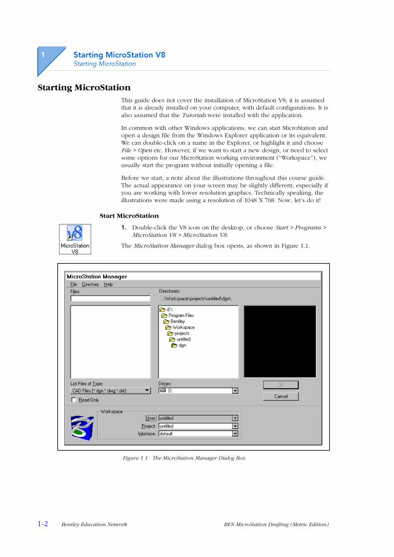
1. Double-click the V8 icon on the desktop, or choose Start > Programs > MicroStation V8 > MicroStation V8.
The MicroStation Manager dialog box opens, as shown in Figure 1.1.
Figure 1.1 The MicroStation Manager Dialog Box

Starting MicroStation V8MicroStation Manager
BEN MicroStation Drafting (Metric Edition) Bentley Education Network 1-3
MicroStation ManagerThe dialog box illustrated in Figure 1.1 provides us with the facilities to manage our files and directories, somewhat like those supplied with Windows Explorer®, but optimized for MicroStation. When working with directories, we can:
• Select drives and directories
• Create new directories
• Backup entire directories
• Compress all files (remove deleted elements) in a directory.
With files, we can:
• Open, copy, rename, move, backup and delete existing files
• Create new files
• Compress individual files.
MicroStation Manager has a “History” menu for both files and directories. It also has combo boxes for the selection of Workspace components.
Selecting Workspace ComponentsWhen we select a Workspace, we are selecting a configuration for MicroStation (a MicroStation “environment”) customized for a specific discipline, project, or task. Workspaces are responsible for personalizing defaults and pointing to locations for the files we need to use.
In the following example, we will select the User Name we were allocated by the course administrator. The files we need will be made available, and the interface will display a relevant selection of tools from the huge selection. Excess tools are removed from the default display to avoid clutter and confusion. We can create, name and save our own workspaces, but we will use the one provided for this course.
Telling MicroStation who we are
1. In the Workspace (lower) panel of the MicroStation Manager dialog, open the User combo box.
Figure 1.2 Changing the User Workspace Component
2. Choose your own user name.
The Project workspace component will automatically change to your own project, the Interface component will remain as Default and the directory and file displays will update to reflect the change.

1
1-4 Bentley Education Network BEN MicroStation Drafting (Metric Edition)
Starting MicroStation V8MicroStation Manager
Backing Up a Design FileWe are often required to keep backup copies of design files. The most obvious reason is for data security which is especially important in the learning environment. Backup copies allow us to experiment on designs without affecting the original data.
In common with most applications, it is conventional to create a backup by copying the original to a file with the same filename, but changing the extension to “.bak”. It may be renamed later as necessary, but in practice MicroStation will open a design file with the “.bak” extension if required. We will now backup the design file that we will be using for our first exercises.
Copying “office.dgn” as a backup
1. Scroll down the list of files and highlight (single-click) “office.dgn”.
2. From the MicroStation Manager Menu bar, choose File > Copy.
The Copy File dialog box opens, with the filename “office.bak” in the To field by default.
If we need to copy a file to another filename and extension, it is simply a matter of editing the To field contents. For this exercise, we will accept “office.bak”.
3. Click the OK button to complete the process.
.
Figure 1.3 Copying to a Backup Design File
The “.bak” file will not appear in the Files panel with this Files of Type selection. To see it we would need to change to “All Files [*.*]”.

Starting MicroStation V8Selecting Workspace Components
BEN MicroStation Drafting (Metric Edition) Bentley Education Network 1-5
Opening a Design FileWe have a selection of existing designs available from the Files panel of MicroStation Manager. We will now open one of those files, “office.dgn”.
Opening “office.dgn”
1. Ensure that the User and Project Workspace components are set to the ones we have been allocated (see page1-3).
2. Highlight (click once only) office.dgn.The Preview panel on the right will display a view of a model,with the information that it is a two-dimensional design in the V8file format.
Figure 1.4 Previewing office.dgn
3. Click OK to open the design file.
The MicroStation V8 application window will open, with a view of the office 2D model displayed in a View window, as shown in Fig. 1.5.
Alternatively, we could have double-clicked the file name without first highlighting it, then it would have opened immediately. However, this way we would have missed out on the preview. A white view background has been used here (and throughout this course guide) for printing purposes.
. . . displays a preview image hereHighlighting a file here . . .
1
1-6 Bentley Education Network BEN MicroStation Drafting (Metric Edition)
Starting MicroStation V8The V8 Application Window
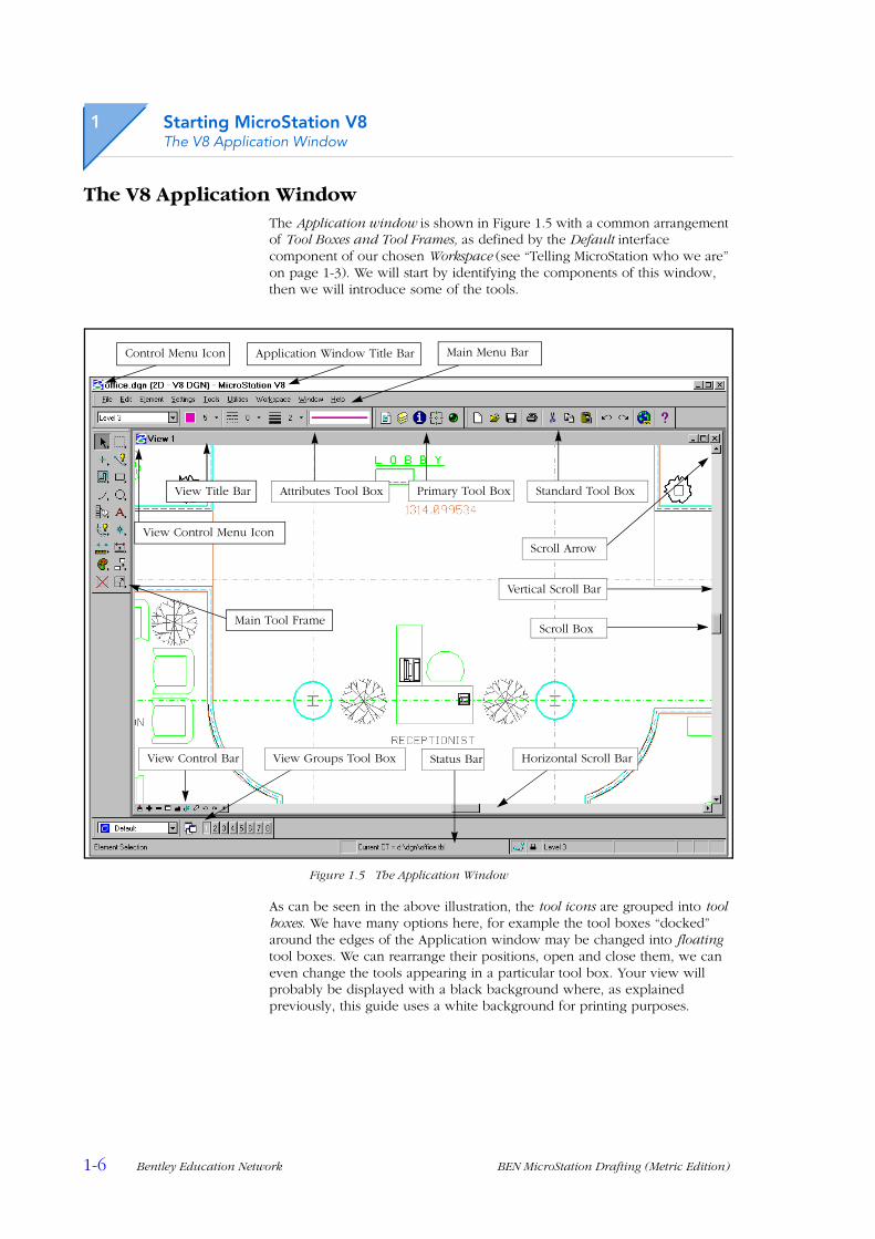
The V8 Application WindowThe Application window is shown in Figure 1.5 with a common arrangement of Tool Boxes and Tool Frames, as defined by the Default interface component of our chosen Workspace (see “Telling MicroStation who we are” on page 1-3). We will start by identifying the components of this window, then we will introduce some of the tools.
Figure 1.5 The Application Window
As can be seen in the above illustration, the tool icons are grouped into tool boxes. We have many options here, for example the tool boxes “docked” around the edges of the Application window may be changed into floating tool boxes. We can rearrange their positions, open and close them, we can even change the tools appearing in a particular tool box. Your view will probably be displayed with a black background where, as explained previously, this guide uses a white background for printing purposes.
View Control Menu Icon
Attributes Tool Box
Scroll Arrow
Status Bar Horizontal Scroll Bar
Scroll Box
Vertical Scroll Bar
Main Menu BarControl Menu Icon Application Window Title Bar
Primary Tool Box Standard Tool Box
Main Tool Frame
View Control Bar View Groups Tool Box
View Title Bar
Starting MicroStation V8Tool Boxes, Tool Frames and Main Menu
BEN MicroStation Drafting (Metric Edition) Bentley Education Network 1-7
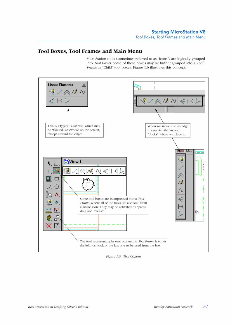
Tool Boxes, Tool Frames and Main MenuMicroStation tools (sometimes referred to as “icons”) are logically grouped into Tool Boxes. Some of these boxes may be further grouped into a Tool Frame as “Child” tool boxes. Figure 1.6 illustrates this concept.
Figure 1.6 Tool Options
Some tool boxes are incorporated into a Tool Frame, where all of the tools are accessed from a single icon. They may be activated by “press, drag and release”.
This is a typical Tool Box, which may be “floated” anywhere on the screen, except around the edges.
When we move it to an edge, it loses its title bar and “docks” where we place it.
The tool representing its tool box on the Tool Frame is either the leftmost tool, or the last one to be used from the box.

1
1-8 Bentley Education Network BEN MicroStation Drafting (Metric Edition)
Starting MicroStation V8Tool Boxes, Tool Frames and Main Menu
Manipulating Tool BoxesAs introduced in Figure 1.6, tool boxes may be “Floated” and “Docked”. The procedure for floating and docking tool boxes is very simple, just “drag and drop”. We are able to have any number of tool boxes open at any time.
Floating and Docking Tool Boxes
The default Application window arrangement in Figure 1.5 has a neat and tidy arrangement of tool boxes around three edges of the window. However, there are occasions when we need to have more tool boxes than this open and there may not be enough space around the edges. The answer to this is to Float tool boxes over parts of the design. Once floating, the tool boxes can be moved or re-docked by “dragging” them by their title bar.
Floating Docked Tool Boxes
1. Position the pointer over the border of the tool box (not on a tool icon) that we wish to float.
2. Press and hold down the data (primary) mouse button, drag out well clear of the tool frame, into the view area.
3. Release the mouse button when we have the outline of the tool box where we want it. The tool box now has a title bar.
Figure 1.7 Floating a Tool Box From its Docked Position
. . . not by a tool icon.
Once the tool box is dragged away from the edge, it gains its own Title Bar. We can move the box later on by dragging this.
The docked tool box needs to be dragged by its border . . .
The new position for the tools is indicated by a rectangle.
Starting MicroStation V8Tool Boxes, Tool Frames and Main Menu
BEN MicroStation Drafting (Metric Edition) Bentley Education Network 1-9
Docking a floating tool box is simply a matter of dragging it by its title bar to the edge where we want it to dock. If there are already tool bars docked at that edge, we can position it where we want it to reside alongside them.
Child tool boxes (see “Tool Boxes, Tool Frames and Main Menu” on page 1-7) are often floated away from their tool frame to allow easier access to the tools. This also displays the range of tools available from that box, which can be a help to new users.
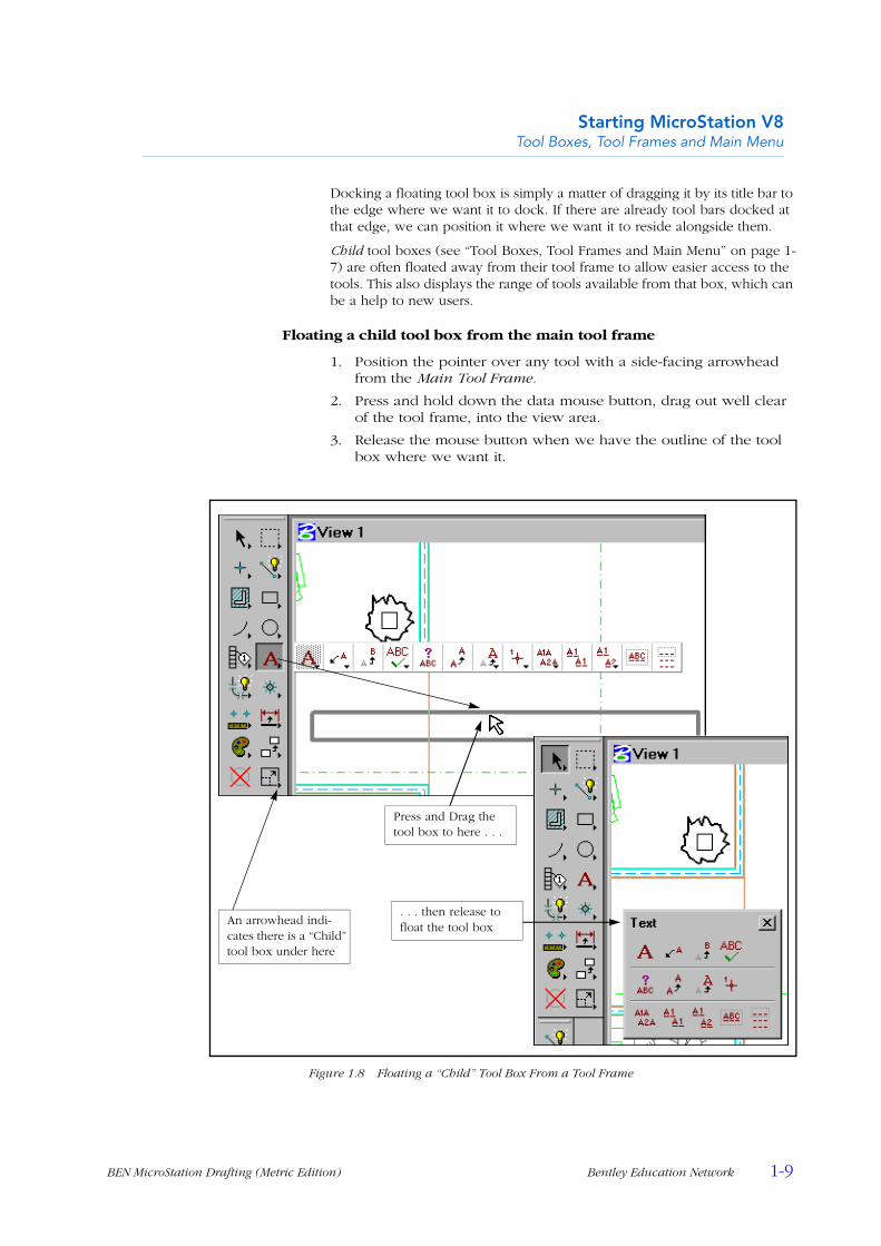
Floating a child tool box from the main tool frame
1. Position the pointer over any tool with a side-facing arrowhead from the Main Tool Frame.
2. Press and hold down the data mouse button, drag out well clear of the tool frame, into the view area.
3. Release the mouse button when we have the outline of the tool box where we want it.
Figure 1.8 Floating a “Child” Tool Box From a Tool Frame
An arrowhead indi-cates there is a “Child” tool box under here
Press and Drag the tool box to here . . .
. . . then release to float the tool box
1
1-10 Bentley Education Network BEN MicroStation Drafting (Metric Edition)
Starting MicroStation V8Tool Boxes, Tool Frames and Main Menu
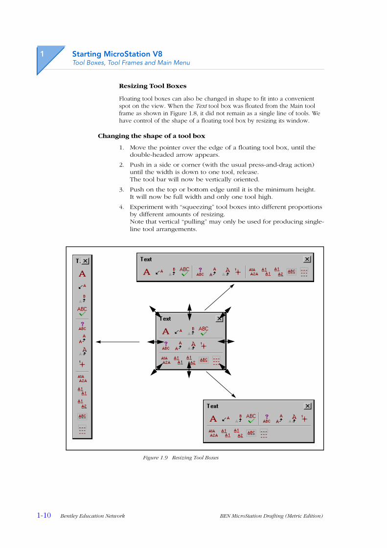
Resizing Tool Boxes
Floating tool boxes can also be changed in shape to fit into a convenient spot on the view. When the Text tool box was floated from the Main tool frame as shown in Figure 1.8, it did not remain as a single line of tools. We have control of the shape of a floating tool box by resizing its window.
Changing the shape of a tool box
1. Move the pointer over the edge of a floating tool box, until the double-headed arrow appears.
2. Push in a side or corner (with the usual press-and-drag action) until the width is down to one tool, release.The tool bar will now be vertically oriented.
3. Push on the top or bottom edge until it is the minimum height.It will now be full width and only one tool high.
4. Experiment with “squeezing” tool boxes into different proportions by different amounts of resizing.Note that vertical “pulling” may only be used for producing single-line tool arrangements.
Figure 1.9 Resizing Tool Boxes

Starting MicroStation V8Tool Boxes, Tool Frames and Main Menu
BEN MicroStation Drafting (Metric Edition) Bentley Education Network 1-11
Main Menu BarThis bar may also be floated like a tool box, or docked at either the top (default) or bottom edge of the Application window. The individual menus will be introduced as we need them; we will not try them all now. However, perhaps one of the most useful of the menus found here is Help, so we shall investigate this one.
Working with the Main menu bar
1. Float and Dock the Main menu bar, using a similar technique to that used in “Floating Docked Tool Boxes” on pages 1-8 and 1-9.
2. Open the Help menu; choose Tool Index as an example.Both the MicroStation Help front page and the Tool Index windows open. The Index option lists all tools and allows us to display help for them. Online Help is an important aid to both learning and using MicroStation. We will be re-introduced to it in more detail at the end of this chapter.
3. Use the dismiss buttons [X] to close both windows.
4. Return the Main menu bar to its correct location.
Figure 1.10 Floating and Using the Main Menu Bar
The Main menu bar must be dragged by the blank area to float it, not by any of the menus.

1
1-12 Bentley Education Network BEN MicroStation Drafting (Metric Edition)
Starting MicroStation V8Tool Boxes, Tool Frames and Main Menu
Closing Tool BoxesWe normally keep the number of tools displayed as low as is practicable, as having too many open reduces the area available on the screen for us to view and create our designs. Large, high resolution screens and multiple screens allow more space for tools. Small screens call for very careful “housekeeping”, closing any tool boxes that we do not currently need.
Closing Tool Boxes With the Dismiss Button
In common with all standard Windows applications, MicroStation tool boxes may be closed by clicking their “dismiss” [X] button. If it is a tool box “torn off” (floated) from a tool frame, closing it will not remove it from the frame. Its tools will still be available using “press-drag-release” (see “Tool Options” on page 1-7). Tool boxes that have been floated from a docked position will be removed, however.
Using the Dismiss button
1. If necessary, float a selection of tool boxes, both “child” tool boxes from the main tool frame and others from the edges of the Application window.See “Floating a child tool box from the main tool frame” on page 1-9 and “Floating Docked Tool Boxes” on page 1-8.
2. Close some of them by clicking their “Dismiss” [X] buttons.Make sure that some of each type remain open.
3. Note that the “child” tool boxes are still available from the Main tool frame (with their “representative” tool still displayed), and that the other tool boxes are nowhere to be seen.
Figure 1.11 Closing Tool Boxes
Another method of closing the tool boxes is via the Tools menu from the Main menu bar.
. . . but other tool boxes just close.
Closing a tool box that was floated from a tool frame does not prevent it from being accessed from the frame . . ..

Starting MicroStation V8Tool Boxes, Tool Frames and Main Menu
BEN MicroStation Drafting (Metric Edition) Bentley Education Network 1-13
Closing tool boxes from the Tools menu
1. Choose (single click) Tools from the Main menu bar.Note that some tool boxes have a checkmark (if not, skip to “Opening Tool Boxes and Tool Frames” on page 1-15, open one or two, then return to here).
2. Click on one of the checked tool box menu items.The menu will close and the chosen tool box will no longer appear.
3. Open the Tools menu again; this time choose Main and an open (checked) child tool box.The child tool box will close, along with the menu.
Figure 1.12 Closing Tool Boxes From the Main Menu
Clicking this item will close the tool box and close the menu at the same time.
To close individual “child” tool boxes, we need to use a tool frame sub-menu, in this case the Main.
The top menu item is the Tool Frame, the others are its included child tool boxes.
1
1-14 Bentley Education Network BEN MicroStation Drafting (Metric Edition)
Starting MicroStation V8Tool Boxes, Tool Frames and Main Menu
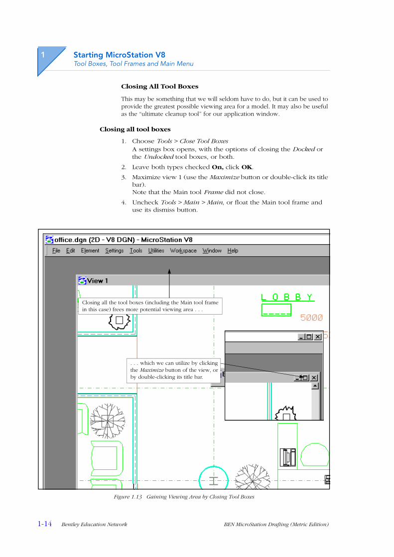
Closing All Tool Boxes
This may be something that we will seldom have to do, but it can be used to provide the greatest possible viewing area for a model. It may also be useful as the “ultimate cleanup tool” for our application window.
Closing all tool boxes
1. Choose Tools > Close Tool BoxesA settings box opens, with the options of closing the Docked or the Undocked tool boxes, or both.
2. Leave both types checked On, click OK.
3. Maximize view 1 (use the Maximize button or double-click its title bar).Note that the Main tool Frame did not close.
4. Uncheck Tools > Main > Main, or float the Main tool frame and use its dismiss button.
Figure 1.13 Gaining Viewing Area by Closing Tool Boxes
Closing all the tool boxes (including the Main tool frame in this case) frees more potential viewing area . . .
. . . which we can utilize by clicking the Maximize button of the view, or by double-clicking its title bar.
Starting MicroStation V8Tool Boxes, Tool Frames and Main Menu
BEN MicroStation Drafting (Metric Edition) Bentley Education Network 1-15
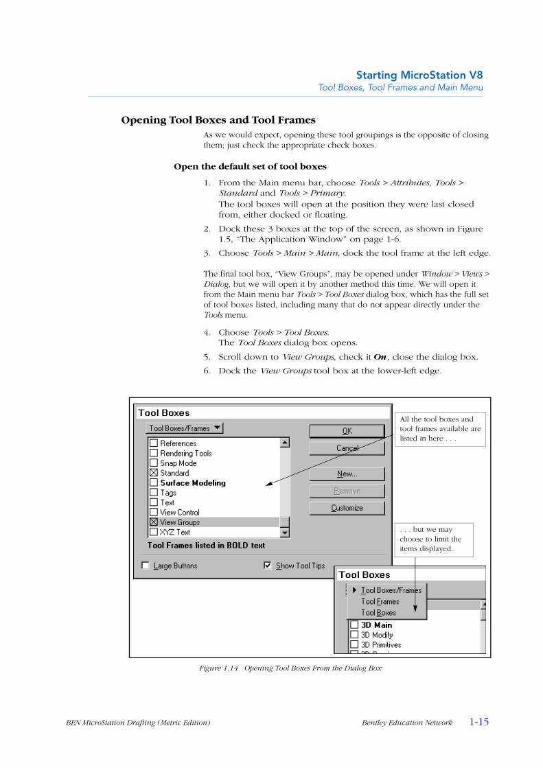
Opening Tool Boxes and Tool FramesAs we would expect, opening these tool groupings is the opposite of closing them; just check the appropriate check boxes.
Open the default set of tool boxes
1. From the Main menu bar, choose Tools > Attributes, Tools > Standard and Tools > Primary.The tool boxes will open at the position they were last closed from, either docked or floating.
2. Dock these 3 boxes at the top of the screen, as shown in Figure 1.5, “The Application Window” on page 1-6.
3. Choose Tools > Main > Main, dock the tool frame at the left edge.
The final tool box, “View Groups”, may be opened under Window > Views > Dialog, but we will open it by another method this time. We will open it from the Main menu bar Tools > Tool Boxes dialog box, which has the full set of tool boxes listed, including many that do not appear directly under the Tools menu.
4. Choose Tools > Tool Boxes.The Tool Boxes dialog box opens.
5. Scroll down to View Groups, check it On, close the dialog box.
6. Dock the View Groups tool box at the lower-left edge.
Figure 1.14 Opening Tool Boxes From the Dialog Box
All the tool boxes and tool frames available are listed in here . . .
. . . but we may choose to limit the items displayed.
1
1-16 Bentley Education Network BEN MicroStation Drafting (Metric Edition)
Starting MicroStation V8Tool Boxes, Tool Frames and Main Menu
Selecting the Tools Displayed in a Tool BoxWe have already seen how to close unwanted tool boxes to make more room on our screen. We will now find out how to keep a tool box open, but reduce the number of tools displayed in it. This may allow a tool box to dock alongside an existing row or column of other tool boxes, rather than wasting valuable “screen real estate” by starting a row or column of its own.
As an example, we will downsize the Standard tool box. This is a tool box that we will need open most of the time, as it has some of the fundamental tools such as Open (to open an existing file) and Print to create a paper document. However, by default it displays some tools we may be able to do without most of the time.
For example, in the default configuration, MicroStation automatically saves all design changes to disk. That means that we do not need the Save Design tool, which is only used when we have MicroStation configured to require manual saves.
The following example will require us to use an alternate mouse button for the first and only time in this chapter. This will be the button on the opposite side to the Data (primary) button, which is conventionally referred to as the Right Button (even though the mouse is configured with the buttons reversed on some occasions, e.g. for left-handed operation).
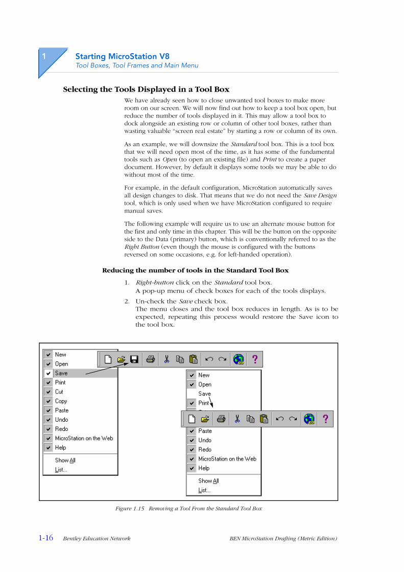
Reducing the number of tools in the Standard Tool Box
1. Right-button click on the Standard tool box.A pop-up menu of check boxes for each of the tools displays.
2. Un-check the Save check box.The menu closes and the tool box reduces in length. As is to beexpected, repeating this process would restore the Save icon tothe tool box.
Figure 1.15 Removing a Tool From the Standard Tool Box
Starting MicroStation V8Design Files, Models and Views
BEN MicroStation Drafting (Metric Edition) Bentley Education Network 1-17
Design Files, Models and Views
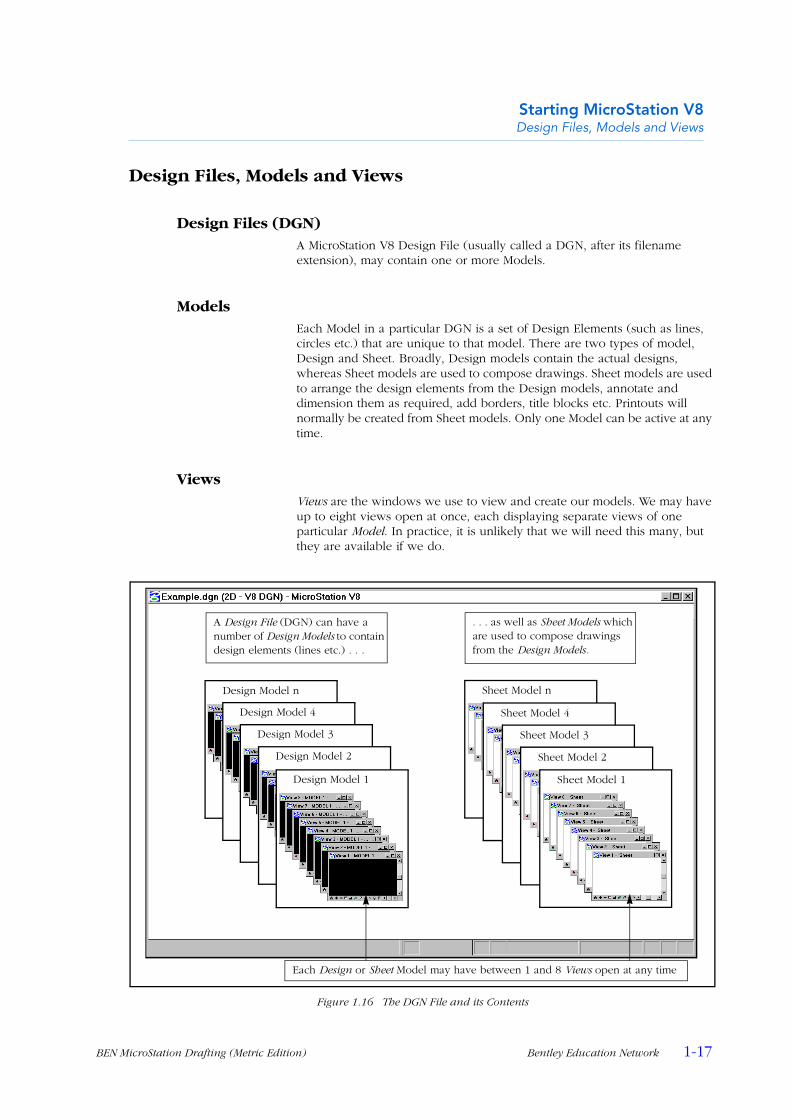
Design Files (DGN)A MicroStation V8 Design File (usually called a DGN, after its filename extension), may contain one or more Models.
ModelsEach Model in a particular DGN is a set of Design Elements (such as lines, circles etc.) that are unique to that model. There are two types of model, Design and Sheet. Broadly, Design models contain the actual designs, whereas Sheet models are used to compose drawings. Sheet models are used to arrange the design elements from the Design models, annotate and dimension them as required, add borders, title blocks etc. Printouts will normally be created from Sheet models. Only one Model can be active at any time.
ViewsViews are the windows we use to view and create our models. We may have up to eight views open at once, each displaying separate views of one particular Model. In practice, it is unlikely that we will need this many, but they are available if we do.
Figure 1.16 The DGN File and its Contents
Design Model n
Design Model 4
Design Model 3
Design Model 2
Design Model 1
Sheet Model n
Sheet Model 4
Sheet Model 3
Sheet Model 2
Sheet Model 1
Each Design or Sheet Model may have between 1 and 8 Views open at any time
A Design File (DGN) can have a number of Design Models to contain design elements (lines etc.) . . .
. . . as well as Sheet Models which are used to compose drawings from the Design Models.
1
1-18 Bentley Education Network BEN MicroStation Drafting (Metric Edition)
Starting MicroStation V8Tools and Tool Settings
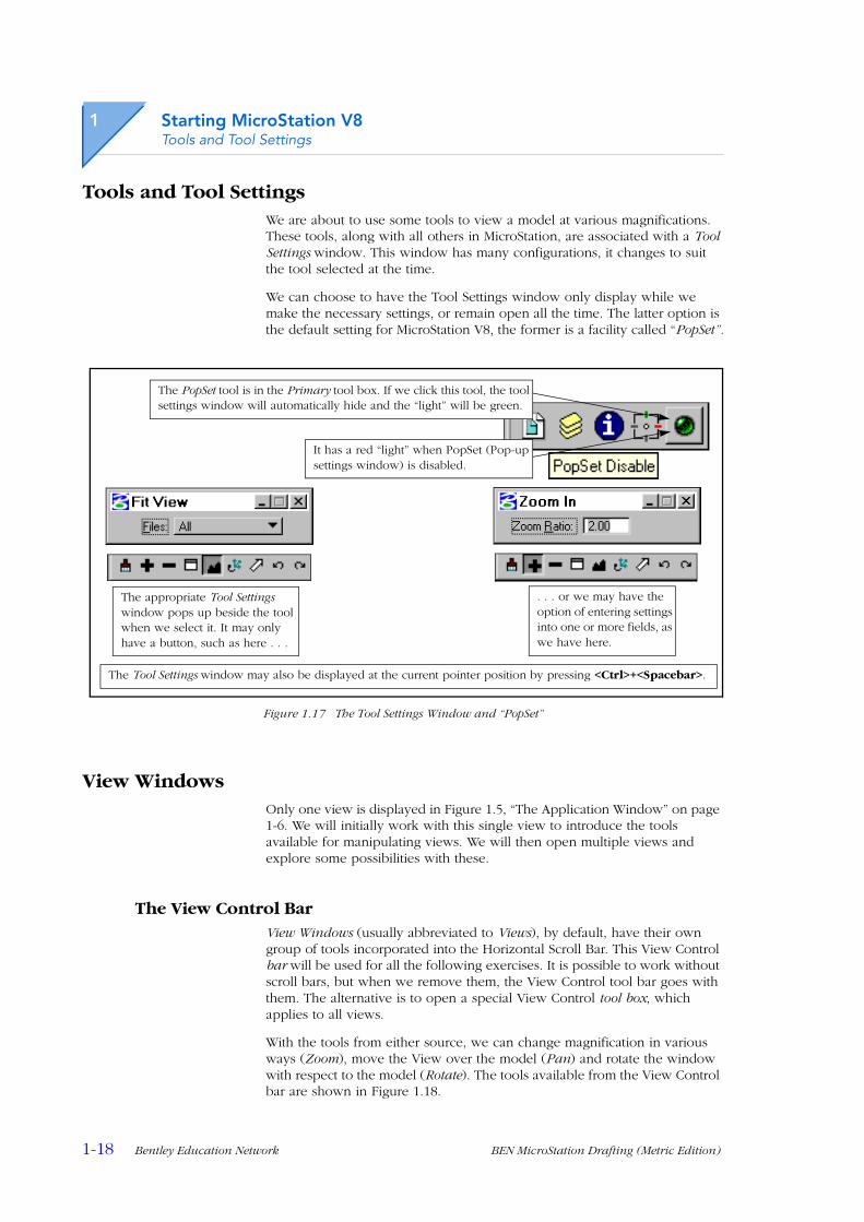
Tools and Tool SettingsWe are about to use some tools to view a model at various magnifications. These tools, along with all others in MicroStation, are associated with a Tool Settings window. This window has many configurations, it changes to suit the tool selected at the time.
We can choose to have the Tool Settings window only display while we make the necessary settings, or remain open all the time. The latter option is the default setting for MicroStation V8, the former is a facility called “PopSet”.
Figure 1.17 The Tool Settings Window and “PopSet”
View WindowsOnly one view is displayed in Figure 1.5, “The Application Window” on page 1-6. We will initially work with this single view to introduce the tools available for manipulating views. We will then open multiple views and explore some possibilities with these.
The View Control BarView Windows (usually abbreviated to Views), by default, have their own group of tools incorporated into the Horizontal Scroll Bar. This View Control bar will be used for all the following exercises. It is possible to work without scroll bars, but when we remove them, the View Control tool bar goes with them. The alternative is to open a special View Control tool box, which applies to all views.
With the tools from either source, we can change magnification in various ways (Zoom), move the View over the model (Pan) and rotate the window with respect to the model (Rotate). The tools available from the View Control bar are shown in Figure 1.18.
The appropriate Tool Settings window pops up beside the tool when we select it. It may only have a button, such as here . . .
. . . or we may have the option of entering settings into one or more fields, as we have here.
It has a red “light” when PopSet (Pop-up settings window) is disabled.
The PopSet tool is in the Primary tool box. If we click this tool, the tool settings window will automatically hide and the “light” will be green.
The Tool Settings window may also be displayed at the current pointer position by pressing <Ctrl>+<Spacebar>.

Starting MicroStation V8The View Control Bar
BEN MicroStation Drafting (Metric Edition) Bentley Education Network 1-19
Figure 1.18 Tools in the View Control Bar
The Update View Tool
This tool is used to “refresh” a view after some of the graphics have been removed by an element manipulation.
Figure 1.19 Updating a View
Update
View
Zoom
In
Zoom
Out
Win
dow Are
a
Fit V
iew
Rotate
Vie
w
Pan
View
View P
revio
us
View N
ext
A line passing through this word was deleted, leaving a gap in the remaining graphics.
The Update View tool refreshes the screen and the missing pixels are restored.
Positioning the pointer over an icon displays its name as a ‘Tool Tip’.
1
1-20 Bentley Education Network BEN MicroStation Drafting (Metric Edition)
Starting MicroStation V8View Windows
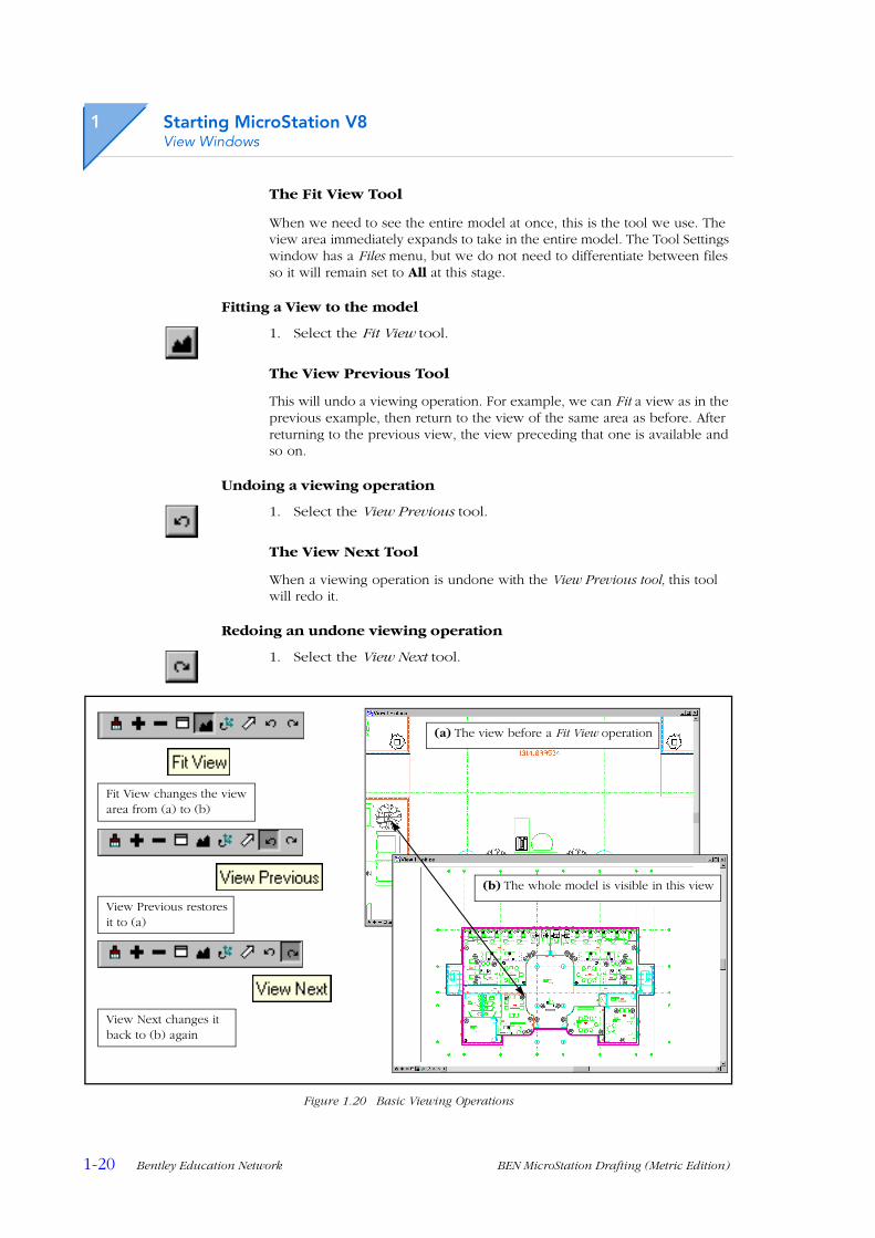
The Fit View Tool
When we need to see the entire model at once, this is the tool we use. The view area immediately expands to take in the entire model. The Tool Settings window has a Files menu, but we do not need to differentiate between files so it will remain set to All at this stage.
Fitting a View to the model
1. Select the Fit View tool.
The View Previous Tool
This will undo a viewing operation. For example, we can Fit a view as in the previous example, then return to the view of the same area as before. After returning to the previous view, the view preceding that one is available and so on.
Undoing a viewing operation
1. Select the View Previous tool.
The View Next Tool
When a viewing operation is undone with the View Previous tool, this tool will redo it.
Redoing an undone viewing operation
1. Select the View Next tool.
Figure 1.20 Basic Viewing Operations
(b) The whole model is visible in this view
(a) The view before a Fit View operation
Fit View changes the view area from (a) to (b)
View Previous restores it to (a)
View Next changes it back to (b) again
Starting MicroStation V8The View Control Bar
BEN MicroStation Drafting (Metric Edition) Bentley Education Network 1-21
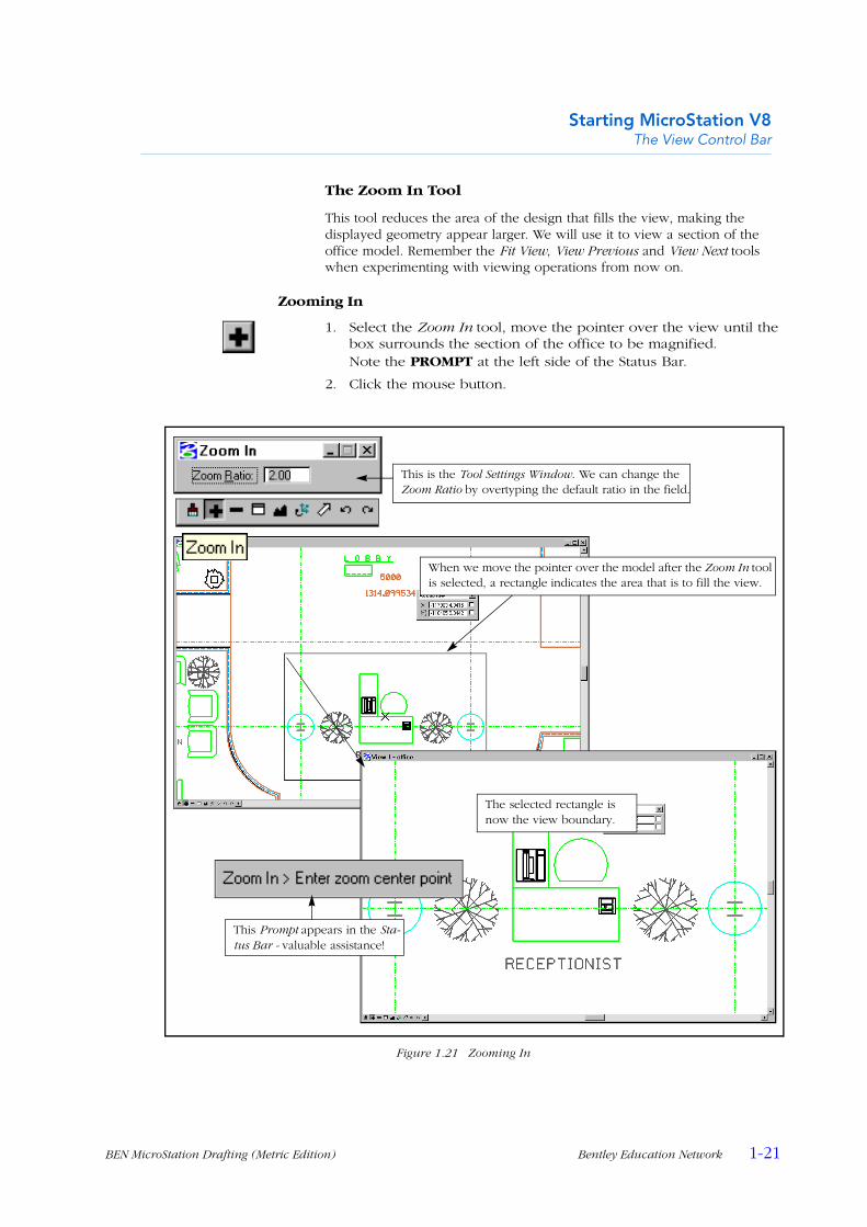
The Zoom In Tool
This tool reduces the area of the design that fills the view, making the displayed geometry appear larger. We will use it to view a section of the office model. Remember the Fit View, View Previous and View Next tools when experimenting with viewing operations from now on.
Zooming In
1. Select the Zoom In tool, move the pointer over the view until the box surrounds the section of the office to be magnified.Note the PROMPT at the left side of the Status Bar.
2. Click the mouse button.
Figure 1.21 Zooming In
The selected rectangle is now the view boundary.
This is the Tool Settings Window. We can change the Zoom Ratio by overtyping the default ratio in the field.
This Prompt appears in the Sta-tus Bar - valuable assistance!
When we move the pointer over the model after the Zoom In tool is selected, a rectangle indicates the area that is to fill the view.

1
1-22 Bentley Education Network BEN MicroStation Drafting (Metric Edition)
Starting MicroStation V8View Windows
The Zoom Out Tool
As is to be expected, this tool decreases a view's magnification, making elements appear smaller.
Zooming Out
1. Select the Zoom Out tool.The View immediately decreases in magnification by the same factor as our Zoom In ratio setting (2 by default). Where Zoom In allows us to set a zoom ratio before zooming, Zoom Out does not because it acts immediately. However, if we select the Zoom In tool first, we can overcome this.
2. Select the Zoom In tool, change the Zoom Ratio by keying in another number (any number between 1 and 50 is valid, but use a small number, say 1.5).
3. Select the Zoom Out tool.The magnification reduces by the ratio as set. The Prompt at the left of the Status Bar invites us to “Enter zoom center point”.
4. Move the pointer into the view area and click.After the first Zoom Out, we are able to select the point tobecome the new center of the view and to change the ZoomRatio.
Figure 1.22 Zooming Out
The Zoom Ratio can be set before zoom-ing out by selecting the Zoom In tool first.
Note the prompt.
When we click the Zoom Out tool the first time, the magnification reduces immediately, then. . .
. . . the ratio can be changed and the center point for the subsequent zoom picked if we leave the tool selected.
Starting MicroStation V8The View Control Bar
BEN MicroStation Drafting (Metric Edition) Bentley Education Network 1-23
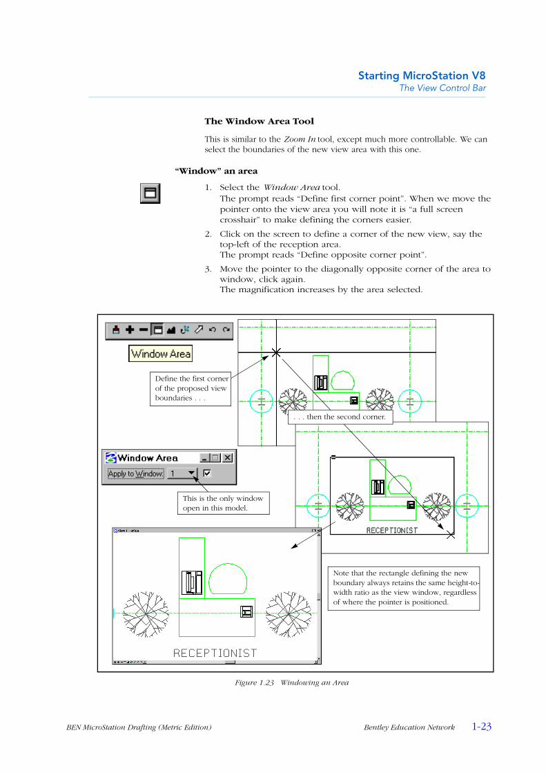
The Window Area Tool
This is similar to the Zoom In tool, except much more controllable. We can select the boundaries of the new view area with this one.
“Window” an area
1. Select the Window Area tool.The prompt reads “Define first corner point”. When we move the pointer onto the view area you will note it is “a full screen crosshair” to make defining the corners easier.
2. Click on the screen to define a corner of the new view, say the top-left of the reception area.The prompt reads “Define opposite corner point”.
3. Move the pointer to the diagonally opposite corner of the area to window, click again.The magnification increases by the area selected.
Figure 1.23 Windowing an Area
Define the first corner of the proposed view boundaries . . .
. . . then the second corner.
Note that the rectangle defining the new boundary always retains the same height-to-width ratio as the view window, regardless of where the pointer is positioned.
This is the only window open in this model.

1
1-24 Bentley Education Network BEN MicroStation Drafting (Metric Edition)
Starting MicroStation V8View Windows
The Pan View Tools
The Scroll Bars on a view window allow us to move the viewing area over a model. This technique is good for large movements, but less so when we need to move a small amount. We can also move the viewing area using the Shift key and Mouse technique. This involves positioning the pointer in the view, holding down the <Shift> key and the data button, then dragging the view over the model.
The most controllable technique of all is to use the Pan View tool. This tool permits precise movements of the window to position a particular point on the model to be exactly where we want it to appear in the view.
Panning the View window with the Scroll Bars
1. Fit the model into the view (“The Fit View Tool” on page 1-20), then window a small area of the office model (“The Window Area Tool” on page 1-23).
2. Use the horizontal and vertical scroll bar handles to move the view window over the model.We tend to be “flying blind” with this technique, as no movement occurs until the mouse button is released.
3. Click in the areas of the scroll bars between the handles and the arrow buttons.The view “pages” through the model, without any overlaps.
4. Click the arrow buttons, then press and hold them down for short periods.The view area moves in discrete steps.
Figure 1.24 Using the Scroll Bars
These buttons pan the view in discrete steps, part of a page at a time.
The handle is only used for large degrees of movement.
Clicking any-where in this area pans a view (page) at a time.

Starting MicroStation V8The View Control Bar
BEN MicroStation Drafting (Metric Edition) Bentley Education Network 1-25
Panning the view window with the Shift key and mouse
1. Position the pointer in the view, hold down the <Shift> key, press the data button and drag the view horizontally and vertically.The speed of the pan will vary with the distance of the pointeraway from its position when we first pressed the mouse button.
Using the Pan View tool
1. Select the Pan View tool, make sure that the Dynamic Display check box is Off in the Tool Settings window.
2. Click on a recognizable element in the model.The prompt reads “Define amount of panning”.
3. Move the pointer to a corner of the view (an arrow “rubber bands” with the pointer), click again.The element selected in step 2 is now positioned in the selected view corner.
4. With the tool still selected, check the Dynamic Display check box On in the Tool Settings window, repeat steps 2 and 3.This time the view window moves with our mouse pointer.
Figure 1.25 Panning with the Pan View Tool
With Dynamic Display unchecked, the arrow represents the From and To points of the pan.
Checking Dynamic Display On enables the view to continu-ously update, so the arrow is not displayed.
This is the point in the view that we panned to.

1
1-26 Bentley Education Network BEN MicroStation Drafting (Metric Edition)
Starting MicroStation V8View Windows
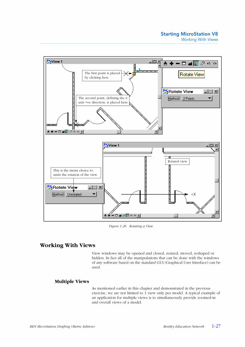
The Rotate View Tool
View rotations can simplify the drafting process when the model needs to be drawn at an angle to the usual Model Axes, where by default the x axis is horizontal on the screen and the y axis is vertical.
For example, assume we need to draw the floor plan of a house in the correct orientation with relation to true North. It is very unlikely for the walls to be exactly North-South and East-West, so by default they will not be parallel with the sides of the view. The Rotate View tool will allow us to rotate the view axis to suit the predominant directions of the lines we are working on. When we rotate a View in MicroStation, we need to keep in mind we are rotating the View Window that we are observing the model through, not rotating the model.
Rotating a view
1. If we still have “office.dgn” open, choose the File > Close option from the Main menu bar, or;Start MicroStation (if necessary) and have the MicroStation Manager dialog box open, with the workspace and directories set as in “Previewing office.dgn” on page 1-5.
2. Highlight “Floor-m.dgn”, create a backup copy (see “Backing Up a Design File” on page 1-4), then open the original.This model will open with four views displayed; we will use View 1.
3. Pan View 1 to show all of the angled wall as in the top image in Figure 1.26 (see “Panning with the Pan View Tool” on page 1-25).It may be necessary to Zoom Out to see the entire wall.
4. Select the Rotate View tool from View 1’s Control bar; if necessary choose 2 Points as the Method from the Tool Settings window.
5. Move the pointer directly over the top corner of the angled wall in View 1, as indicated in Fig. 1.26, then click the data button.The prompt is now “Define X axis of view”.
6. Move the pointer down and to the left, until it is over the other end of the angled wall, click again here.The view window will appear to stay still and the model rotate, but as we learned above, technically this is not the case.
7. Pan the view to see the outside wall etc., then click the Rotate View tool again, choosing Unrotated from the Tool Settings window, then identify View 1 by clicking the data button in it.The identified view will rotate back to its original orientation.
The x axis, as in the mathematical convention, runs horizontally from left to right. When we defined it in steps 5 and 6, we selected the top of the angled wall, then the bottom. This resulted in the model appearing in the view with what was formerly its bottom at the right of the screen.
The points defining this rotation were placed precisely with the help of a facility called AccuSnap. This attracted the pointer to the ends of linework and displayed a special indicator. We will learn more about this facility a little later in the course.
Starting MicroStation V8Working With Views
BEN MicroStation Drafting (Metric Edition) Bentley Education Network 1-27
Figure 1.26 Rotating a View
Working With ViewsView windows may be opened and closed, resized, moved, reshaped or hidden. In fact all of the manipulations that can be done with the windows of any software based on the standard GUI (Graphical User Interface) can be used.
Multiple ViewsAs mentioned earlier in this chapter and demonstrated in the previous exercise, we are not limited to 1 view only per model. A typical example of an application for multiple views is to simultaneously provide zoomed-in and overall views of a model.
+X
This is the menu choice to undo the rotation of the view
Rotated view
The second point, defining the x axis +ve direction, is placed here
The first point is placed by clicking here
1
1-28 Bentley Education Network BEN MicroStation Drafting (Metric Edition)
Starting MicroStation V8Working With Views
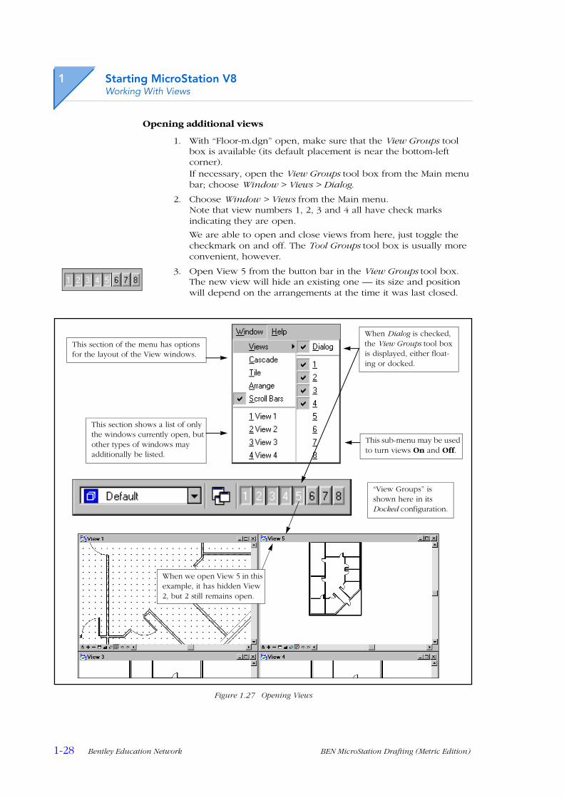
Opening additional views
1. With “Floor-m.dgn” open, make sure that the View Groups tool box is available (its default placement is near the bottom-left corner). If necessary, open the View Groups tool box from the Main menu bar; choose Window > Views > Dialog.
2. Choose Window > Views from the Main menu.Note that view numbers 1, 2, 3 and 4 all have check marks indicating they are open.
We are able to open and close views from here, just toggle the checkmark on and off. The Tool Groups tool box is usually more convenient, however.
3. Open View 5 from the button bar in the View Groups tool box.The new view will hide an existing one — its size and position will depend on the arrangements at the time it was last closed.
Figure 1.27 Opening Views
This section of the menu has options for the layout of the View windows.
This section shows a list of only the windows currently open, but other types of windows may additionally be listed.
When Dialog is checked, the View Groups tool box is displayed, either float-ing or docked.
“View Groups” is shown here in its Docked configuration.
When we open View 5 in this example, it has hidden View 2, but 2 still remains open.
This sub-menu may be used to turn views On and Off.

Starting MicroStation V8Multiple Views
BEN MicroStation Drafting (Metric Edition) Bentley Education Network 1-29
Automatic View ArrangementsWe may organize our multiple views as we need by resizing and moving them within the Application window. MicroStation will also arrange them automatically for us if this suits our requirements.
Standard View Arrangements
1. Have “Floor-m.dgn” open, with all 5 views remaining open from the last example.
2. Choose Window > Cascade from the Main menu.All 5 windows are partly visible, with only the front one useful for viewing and drawing.
3. Practice bringing other views to the front by clicking on any visible part of their borders or title bars.
4. Practice bringing other views to the front by choosing them from the Window menu.
Figure 1.28 Cascading Views
A view may be brought to the front by clicking on any visible part of its border or title bar . . .
. . . or by choosing it from the Window menu
1
1-30 Bentley Education Network BEN MicroStation Drafting (Metric Edition)
Starting MicroStation V8Working With Views
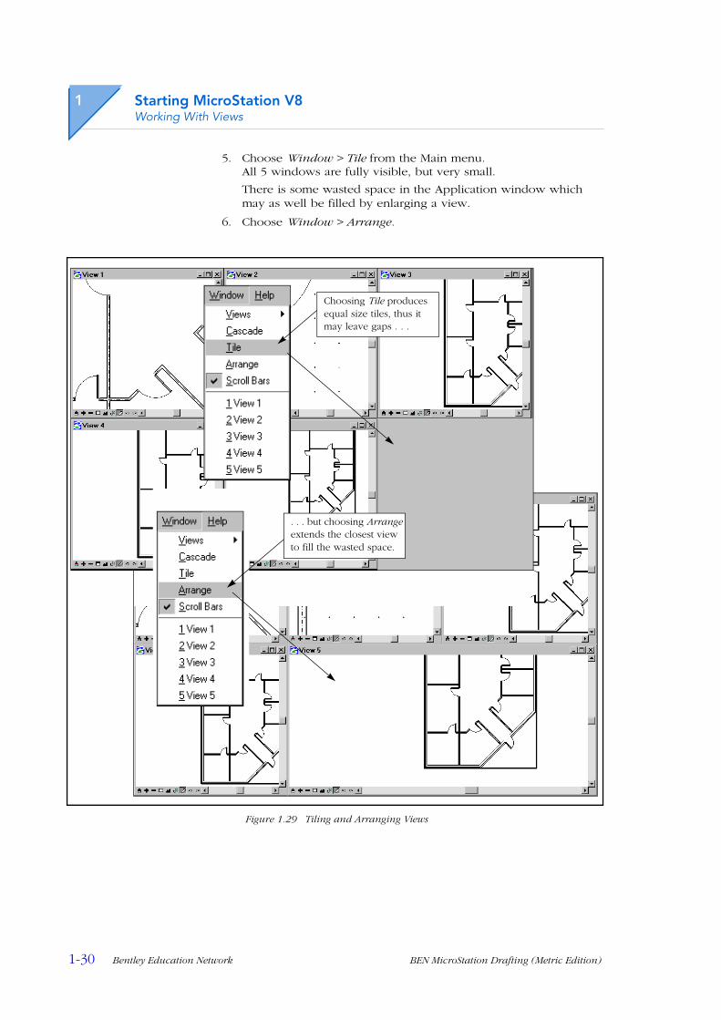
5. Choose Window > Tile from the Main menu.All 5 windows are fully visible, but very small.
There is some wasted space in the Application window which may as well be filled by enlarging a view.
6. Choose Window > Arrange.
Figure 1.29 Tiling and Arranging Views
. . . but choosing Arrange extends the closest view to fill the wasted space.
Choosing Tile produces equal size tiles, thus it may leave gaps . . .
Starting MicroStation V8Multiple Views
BEN MicroStation Drafting (Metric Edition) Bentley Education Network 1-31
Saving a View GroupWe are able to Name and Save groups of views that suit a particular operation, so that we can repeat the arrangement as needed later on. It is likely that we will use a variety of view groups during the life of a design exercise.
When we restore a saved View Group, it will be arranged exactly as it was the last time we used it. The usual process for saving a view group is to create the group name first, then arrange the views. We will name the group in the next exercise, then arrange the views in the following one.
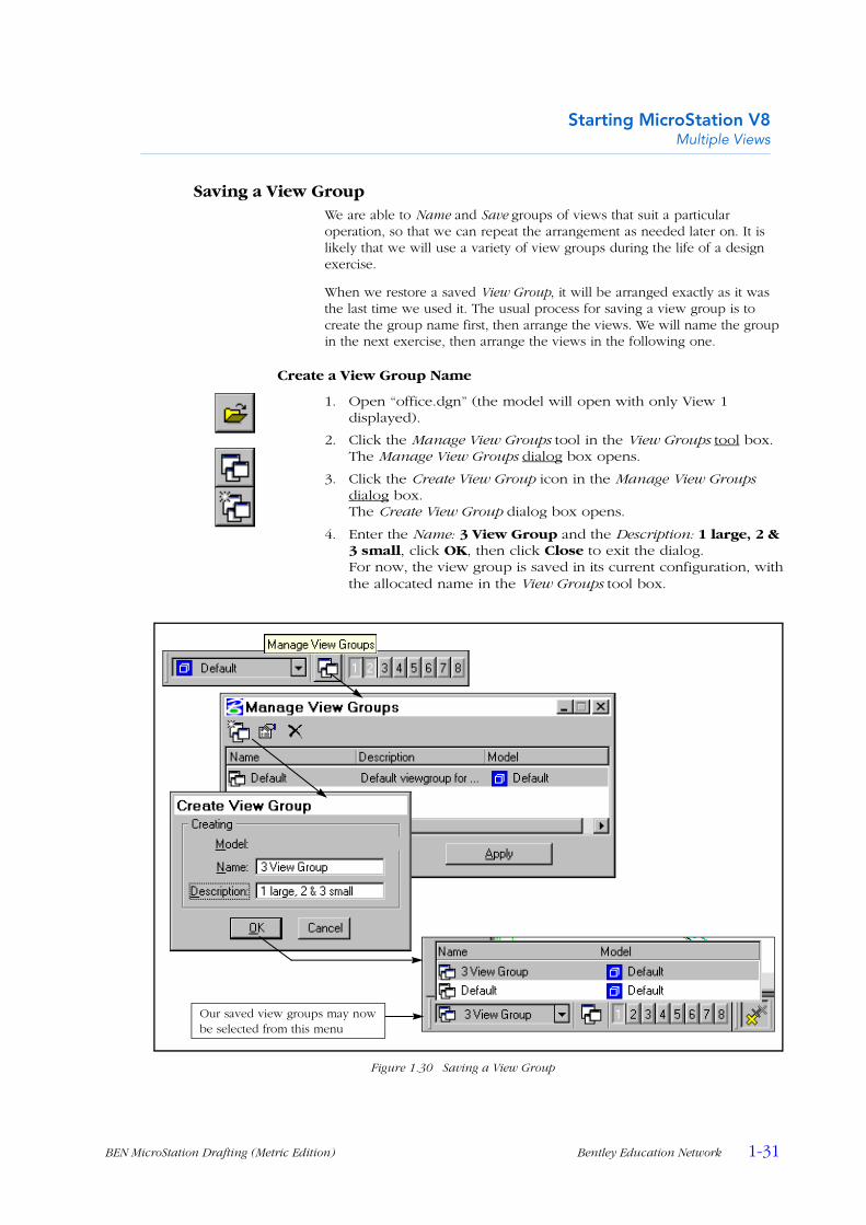
Create a View Group Name
1. Open “office.dgn” (the model will open with only View 1 displayed).
2. Click the Manage View Groups tool in the View Groups tool box.The Manage View Groups dialog box opens.
3. Click the Create View Group icon in the Manage View Groups dialog box.The Create View Group dialog box opens.
4. Enter the Name: 3 View Group and the Description: 1 large, 2 & 3 small, click OK, then click Close to exit the dialog.For now, the view group is saved in its current configuration, withthe allocated name in the View Groups tool box.
Figure 1.30 Saving a View Group
Our saved view groups may now be selected from this menu

1
1-32 Bentley Education Network BEN MicroStation Drafting (Metric Edition)
Starting MicroStation V8Working With Views
Customizing Groups of ViewsThe techniques for moving and resizing view windows are identical to those used in all standard Windows applications. We have already been introduced to these in MicroStation when we were working with Tool Boxes, see “Floating and Docking Tool Boxes” on page 1-8 and “Resizing Tool Boxes” on page 1-10. In the following example, we will create a group of views of the “office” model.
We will arrange a group of views under the name created in the previous exercise.
Creating a group of 3 views
1. With “office.dgn” open, ensure that “3 View Group” is the named group chosen in the View Groups tool box.
2. Open Views 2 and 3 from the button bar, also in the View Groups tool box.
3. Reduce the width of Views 2 & 3 to approximately one third of the Application window. Adjust their heights if necessary for them to fit above one another without overlap.
4. Bring View 1 to the front by clicking it under the Window menu.
5. Reduce the width of View 1 to fit beside views 3 & 4, without any overlap.This is now the view arrangement saved as “3 View Group”, it has updated the previous definition.
6. Swap back and forward between “3 View Group” and “Default”, note how the definition remains as it was the last time the named group was in use.
7. Try changing the view arrangement while “Default” is chosen, then swap between the groups again.
Figure 1.31 A Typical 3 View Group

Starting MicroStation V8Multiple Views
BEN MicroStation Drafting (Metric Edition) Bentley Education Network 1-33
Saved ViewsEarlier in this chapter we used the various tools from the View Control bar to “window” a particular area of a model. It will be necessary to change view definitions frequently as we progress through the design process, but we also need to return to a particular definition from time to time. To provide for this, we have the Saved View facility to name and save view definitions for later recall.
So far, we have saved view groups. Now we will save the particular area of the model as it appears in one view. Apart from the area of the model displayed, some other information may be saved with the view (Levels, View Attributes etc.). These topics will be introduced later in the course.
Saving a View Definition
1. With “office.dgn” open and the 3 View Group displayed, use any of the View Control tools (p1-19) to change the displayed area of the model in View 1.
2. Click View 1’s View Control Menu Icon (the “B” on the left end of the View title bar), choose View Save/Recall.The Saved Views dialog box opens.
This dialog may also be opened from the Main menu by choosing Utilities > Saved Views.
3. If necessary, check the Camera Position, View Attributes and Levels check boxes On, the remainder Off.
Figure 1.32 Preparing to Save a View Definition
When we open this box from the View menu icon, the View number defaults to that of the one we opened it from.
The Camera Position refers to the “virtual cam-era” focussed on the view. This must be checked On to save the “windowing” of the view.
1
1-34 Bentley Education Network BEN MicroStation Drafting (Metric Edition)
Starting MicroStation V8Working With Views
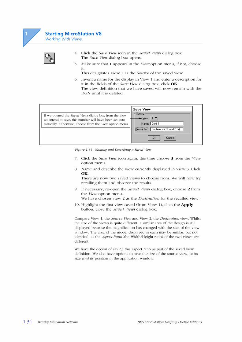
4. Click the Save View icon in the Saved Views dialog box.The Save View dialog box opens.
5. Make sure that 1 appears in the View option menu, if not, choose it.This designates View 1 as the Source of the saved view.
6. Invent a name for the display in View 1 and enter a description for it in the fields of the Save View dialog box, click OK.The view definition that we have saved will now remain with the DGN until it is deleted.
Figure 1.33 Naming and Describing a Saved View
7. Click the Save View icon again, this time choose 3 from the View option menu.
8. Name and describe the view currently displayed in View 3. Click OK.There are now two saved views to choose from. We will now try recalling them and observe the results.
9. If necessary, re-open the Saved Views dialog box, choose 2 from the View option menu.We have chosen view 2 as the Destination for the recalled view.
10. Highlight the first view saved (from View 1), click the Apply button, close the Saved Views dialog box.
Compare View 1, the Source View and View 2, the Destination view. Whilst the size of the views is quite different, a similar area of the design is still displayed because the magnification has changed with the size of the view window. The area of the model displayed in each may be similar, but not identical, as the Aspect Ratio (the Width/Height ratio) of the two views are different.
We have the option of saving this aspect ratio as part of the saved view definition. We also have options to save the size of the source view, or its size and its position in the application window.
If we opened the Saved Views dialog box from the view we intend to save, this number will have been set auto-matically. Otherwise, choose from the View option menu.
Starting MicroStation V8Multiple Views
BEN MicroStation Drafting (Metric Edition) Bentley Education Network 1-35
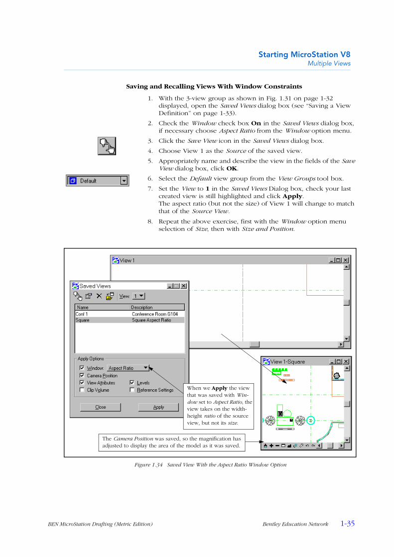
Saving and Recalling Views With Window Constraints
1. With the 3-view group as shown in Fig. 1.31 on page 1-32 displayed, open the Saved Views dialog box (see “Saving a View Definition” on page 1-33).
2. Check the Window check box On in the Saved Views dialog box, if necessary choose Aspect Ratio from the Window option menu.
3. Click the Save View icon in the Saved Views dialog box.
4. Choose View 1 as the Source of the saved view.
5. Appropriately name and describe the view in the fields of the Save View dialog box, click OK.
6. Select the Default view group from the View Groups tool box.
7. Set the View to 1 in the Saved Views Dialog box, check your last created view is still highlighted and click Apply.The aspect ratio (but not the size) of View 1 will change to match that of the Source View.
8. Repeat the above exercise, first with the Window option menu selection of Size, then with Size and Position.
Figure 1.34 Saved View With the Aspect Ratio Window Option
The Camera Position was saved, so the magnification has adjusted to display the area of the model as it was saved.
When we Apply the view that was saved with Win-dow set to Aspect Ratio, the view takes on the width-height ratio of the source view, but not its size.
1
1-36 Bentley Education Network BEN MicroStation Drafting (Metric Edition)
Starting MicroStation V8Help
HelpWe had a very brief look at the Help menu from the Main menu bar on page 1-11, where we viewed the Tool Index. We can also access Help Contents, Search etc. from the Standard tool box (see “The V8 Application Window” on page 1-6). Using Help frequently does not use time, it saves time. We do not only obtain answers to the questions that cause us to open Help initially, we often pick up valuable extra information on the way. Use help frequently during this course, as there are many more pages of information available from this facility than could ever practicably be included in a course guide.
The primary level of help for tools is to pause the pointer over the tool, waiting for its Tool Tip to appear. As well as the Tool Tip a brief description of the tool appears in the Status Bar. However, because we often need more complex assistance than this, we can use Tracking Help.
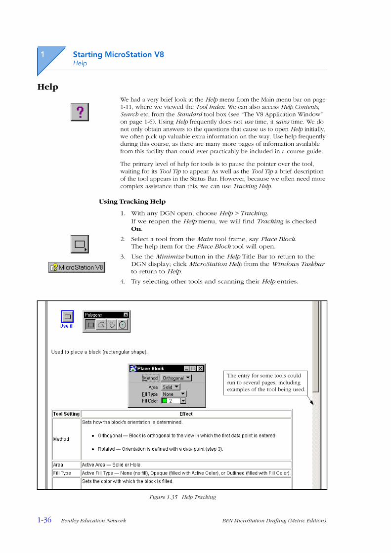
Using Tracking Help
1. With any DGN open, choose Help > Tracking.If we reopen the Help menu, we will find Tracking is checked On.
2. Select a tool from the Main tool frame, say Place Block.The help item for the Place Block tool will open.
3. Use the Minimize button in the Help Title Bar to return to the DGN display; click MicroStation Help from the Windows Taskbar to return to Help.
4. Try selecting other tools and scanning their Help entries.
Figure 1.35 Help Tracking
The entry for some tools could run to several pages, including examples of the tool being used.