Valve terminal type 03/05 with field bus connection … · Valve terminal type 03/05 with field bus...
211
Valve terminal type 03/05 with field bus connection FB11 Electronics Manual Field bus protocol: Allen-Bradley DeviceNet Philips DIOS Selectron SELECAN 163 956 GB 9902d
Transcript of Valve terminal type 03/05 with field bus connection … · Valve terminal type 03/05 with field bus...

Valve terminal type 03/05with field bus connection FB11
Electronics Manual
Field bus protocol:Allen-Bradley DeviceNet
Philips DIOSSelectron SELECAN
163
956
GB
9902d

Author: S. Breuer, H. Hohner, E. Klotz
Editor: H.-J. Drung, M. Holder
Translation: Douglas Smith
Layout: Festo, Dept. KI-TD
Type setting: S. Breuer, DUCOM
9902d
1999 Festo AG & Co., D-73726 Esslingen,Federal Republic of Germany
The copying, distribution and utilization of thisdocument as well as the communication of itscontents to others without expressed authori-zation is prohibited. Offenders will be heldliable for the payment of damages. All rightsreserved, in particular the right to carry outpatent, utility model or ornamental designregistrations.pr
inte
d on
10
0% r
ecy
cled
pap
erVIFB11 - 03/05
9902d I

Part no.: 163 956
Titel: MANUAL
Designation: P.BE-VIFB11-03/05-GB
VIFB11 - 03/05
II 9902d
Contents
GENERAL SAFETY INSTRUCTIONS IXDesignated use IXTarget group X
IMPORTANT USER INSTRUCTIONS XIDanger categories XIPictograms XIIManuals for valve terminals types 03/05 XIIINotes on this manual XIVService XVI
Chapter 1 SYSTEM SUMMARY
1.1 SYSTEM SUMMARY 1-3System structure 1-3Type 03: Description of components 1-5Type 05: Description of components 1-9
Chapter 2 FITTING
2.1 FITTING THE COMPONENTS 2-3Input/output modules 2-4End plates 2-6Hat rail clamping unit (type 03) 2-8
2.2 TYPE 03: FITTING THE VALVE TERMINAL 2-9Fitting onto a wall (type 03) 2-9Fitting onto a hat rail (type 03) 2-10
2.3 TYPE 05: FITTING THE VALVE TERMINAL 2-12Fitting onto a wall (type 05) 2-12
VIFB11 - 03/05
9902d III

Chapter 3 INSTALLATION
3.1 GENERAL CONNECTION TECHNIQUES 3-3Selecting the field bus cable 3-4Selecting the operating voltage cable 3-5Connecting the cables to the plugs/sockets 3-6
3.2 FIELD BUS NODE 3-8Opening and closing the node 3-8Configuring the valve terminal 3-10Setting the station number 3-11Possible station numbers 3-12Setting the field bus baud rate 3-14Setting the field bus protocol 3-15Setting the compatibility (DeviceNet configuration) 3-16
3.2.1 Type 03: Connecting the operating voltages 3-18Calculating the current consumption for type 03 3-21Connection example (type 03) 3-23
3.2.2 Type 05: Connecting the operating voltages 3-25Calculating the current consumption for type 05 3-28Connection example (type 05) 3-30
3.2.3 Connecting the field bus 3-32Connection instructions for Philips DIOS 3-36Connection instr. for Selectron SELECAN 3-37Connection instr. for Allen-Bradley DeviceNet 3-38Connection instructions for Festo DeviceNet (SF 60) 3-38Terminating resistor 3-39
VIFB11 - 03/05
IV 9902d

Chapter 4 COMMISSIONING
4.1 BASIC PRINCIPLES OF CONFIGURATION AND ADDRESSING 4-5General 4-5Switching on the operating voltage 4-6Calculating the configuration data 4-7Calculating the number of inputs/outputs 4-9Address assignment of the valve terminal 4-11General information on type 03 and type 05 4-11Basic rule 1 4-12Basic rule 2 4-15Basic rule 3 4-15Address assignment after extension/conversion 4-16
4.2 BASIC PRINCIPLES OF COMMISSIONING AND DIAGNOSIS 4-18
4.2.1 Philips Dios 4-18General 4-18Configuration 4-20Example 4-21Addressing the inputs/outputs 4-22Program example 4-24Diagnosis 4-25Diagnosis via DLC 100/200 4-25Diagnosis via the user program 4-26Diagnostic objects of the system 4-26Status bits 4-27
VIFB11 - 03/05
9902d V

4.2.2 SELECTRON SELECAN 4-29General 4-29Configuration 4-31Addressing the inputs/outputs 4-32Program example 4-34Diagnosis 4-35Diagnosis via the PMC 40 4-35Diagnosis via the user program 4-35System flags SM11.01 - SM11.29 4-35System flags SM12.01 - SM12.29 4-36Status bits 4-36
4.2.3 Allen-Bradley DeviceNet 4-39General 4-39Festo SF 60 as DeviceNet master 4-41CD ROM "Utilities" 4-41Extending the EDS library 4-42Installing the EDS file (recommended variant) 4-43Extending the network with a valve terminal 4-44Configuring the scanner 4-47Entering the number of I/Os 4-48Assignment and transmission mode 4-51Scanner 1771-SDN (PLC 5 series) 4-55Scanner 1747-SDN (SF 60 and SLC 500 series) 4-56Example 1: Scanner 1771-SDN (PLC 5 series) 4-57Example 2: Scanner 1747-SDN(SLC 500 series) 4-59Explicit message 4-61Diagnosis 4-62Diagnosis via DeviceNet scanner 4-62Diagnosis via user program 4-62Device failure table 4-62Status bits 4-63
VIFB11 - 03/05
VI 9902d

Chapter 5 DIAGNOSIS AND ERROR TREATMENT
5.1 SUMMARY OF DIAGNOSTIC POSSIBILITIES 5-3
5.2 ON-THE-SPOT DIAGNOSIS 5-4LED display (node) 5-4Valves 5-7Input/output modules 5-9Testing the valves 5-10
5.3 STATUS BITS 5-12
5.4 ERROR TREATMENT 5-15Reaction to faults in the control system 5-15Short circuit/overload at an output module 5-16
Appendix A DEVICENET SPECIFICATIONS
A.1 OVERVIEW DEVICENET-SPECIFICATIONS A-3General DeviceNet Information A-3DeviceNet - Message Types A-4DeviceNet - Class and Instance Services A-4DeviceNet - Object Classes A-4
A.2 DETAILS ON DEVICENET OBJECTS A-5
A.2.1 Identity Object: Class Code 01 (0x01) A-5
A.2.2 Router Object: Class Code 02 (0x02) A-7
A.2.3 DeviceNet Object: Class Code 03 (0x03) A-8
A.2.4 Assembly Object: Class Code 04 (0x04) A-10
A.2.5 Connection Object: Class Code 05 (0x05) A-13
VIFB11 - 03/05
9902d VII

Appendix B TECHNICAL APPENDIX
B.1 TECHNICAL SPECIFICATIONS B-3
B.2 CABLE LENGTH AND CROSS-SECTIONAL AREA B-7Calculating with a graph B-8Calculating with a formula B-10
B.3 EXAMPLES OF CIRCUITRY B-12Operating voltage connection type 03 B-12Operating voltage connection type 05 B-13
B.4 ACCESSORIES B-14Bus connection B-14
B.5 DEVICENET COMPATIBILITY - CONFIGURATION OF SOFTWARE VERSION V1.3/1.4 B-17EDS library: Entering slaves manually B-18
Appendix C INDEX
VIFB11 - 03/05
VIII 9902d

GENERAL SAFETY INSTRUCTIONS
Designated use
The valve terminals types 03/05 described inthis manual are designated exclusively for useas follows:
• for controlling pneumatic and electricalactuators (valves and output modules)
• for interrogating electrical sensor signals bymeans of the input modules.
Use the valve terminals only as follows:
• as designated in the instructions
• in technically faultless condition
• without any modifications.
The specified limit values for pressures, tem-peratures, electrical data, torques, etc. must beobserved when additional commercially-avail-able components such as sensors and actua-tors are connected.
Please comply also with national and localsafety laws and regulations.
VIFB11 - 03/05 General safety instructions
9902d IX

Target group
This manual is directed exclusively at techni-cians who are trained in control and automat-ion technology and who have experience ininstalling, commissioning, programming anddiagnosing programmable logic controllers(PLC) and field bus systems.
VIFB11 - 03/05 General safety instructions
X 9902d

IMPORTANT USER INSTRUCTIONS
Danger categories
This manual contains instructions on thepossible dangers which can occur when thevalve terminals types 03/05 are used.
A distinction is made between the followinginstructions:
WARNINGThis means that injury to human beings aswell as material damage can occur if these in-structions are not observed.
CAUTIONThis means that material damage can occur ifthese instructions are not observed.
PLEASE NOTEThis means that this instruction must also beobserved.
VIFB11 - 03/05 General safety instructions
9902d XI

Pictog rams
Pictograms and symbols supplement thedanger instructions and draw attention to theconsequences of dangers. The following picto-grams are used:
Uncontrolled movements of loose tubing.
Uncontrolled movement of the connected actu-ators.
High electric voltage or undefined switchingstates of the electronic components whichaffect the connected circuits.
Electrostatically vulnerable components whichwill be destroyed if their contact surfaces aretouched.
The ISO valve terminal type 05 is very heavy.Please ensure that it is fastened correctly andsee that all operating personnel wear safetyshoes.
VIFB11 - 03/05 General safety instructions
XII 9902d

Manuals for valve terminals types 03/05
The following Festo manuals are required tocomplete the documentation for the valveterminal, depending on the terminal you haveordered and on the equipment fitted on yoursystem:
Festo order no.
Title
Valve terminals 03/05
152 771 Pneumatics manual• Valve terminal type 03 MIDI/MAXI
163 941 Pneumatics manual• Valve terminal type 04-B, ISO 5599-2
152 773 Pneumatics manual• Valve terminal type 05, ISO 5599-1
371 190 Supplementary manuals for I/O modules(digital I/O modules 4E, 8E, 4A, high-current output modules, multi I/O modules)
163 956 Electronics manual • Field bus connection FB11
(this manual)
Fig. 0/1: Manuals for valve terminals types 03/05
VIFB11 - 03/05 General safety instructions
9902d XIII
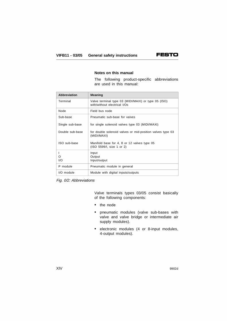
Notes on this manual
The following product-specific abbreviationsare used in this manual:
Valve terminals types 03/05 consist basicallyof the following components:
• the node
• pneumatic modules (valve sub-bases withvalve and valve bridge or intermediate airsupply modules).
• electronic modules (4 or 8-input modules,4-output modules).
Abbreviation Meaning
Terminal Valve terminal type 03 (MIDI/MAXI) or type 05 (ISO)with/without electrical I/Os
Node Field bus node
Sub-base
Single sub-base
Double sub-base
ISO sub-base
Pneumatic sub-base for valves
for single solenoid valves type 03 (MIDI/MAXI)
for double solenoid valves or mid-position valves type 03(MIDI/MAXI)
Manifold base for 4, 8 or 12 valves type 05(ISO 5599/I, size 1 or 2)
IOI/O
InputOutputInput/output
P module Pneumatic module in general
I/O module Module with digital inputs/outputs
Fig. 0/2: Abbreviations
VIFB11 - 03/05 General safety instructions
XIV 9902d

This electronics manual describes node FB11.
PLEASE NOTEA valve terminal with four pneumatic valvesub-bases and four input/output modules isused for the diagrams in this manual.
Fig. 0/3: Standard fitting for the drawings
VIFB11 - 03/05 General safety instructions
9902d XV

The valve terminals can be connected to thecontrol systems of various manufacturers. Thismanual deals with the configuration of the PLCand the addressing of the terminals for thefollowing controllers:
DeviceNet field bus protocol
PLEASE NOTEThis manual refers to valve terminals withfield bus connection FB11 as from softwarestatus 26.02.99 (see type plate) or to softwareversion 2.0 (see sticker on operating systemEPROM) or later.As from this software status the configurationof the valve terminal is supported by two EDSfiles. This manual describes commissioningwith the DeviceNet manager V3.005.
Service
If you have any technical problems, pleaseconsult your local Festo Service.
Controllermanufacturer
Controller (PLC) Field bus module/interface
Field bus
Allen-Bradley PLC 5/xxSLC 500PC/IPC
1771-SDN1747-SDN1170-KFD DeviceNet
Festo SF 60 1747-SDN
Philips P8 Compact line DLC 100/200 DIOS
Selectron PMC 40MASPC / IPC
CPU 42CPU 751/752PCI 701
RDCSELECANSELECAN
Siemens S5-115U ... 155U CAN-CSC515 from ESD DeviceNet
Fig. 0/4: Summary of possible controllers/field bus protocols (extract)
VIFB11 - 03/05 General safety instructions
XVI 9902d

1. SYSTEM SUMMARY
VIFB11 - 03/05 1. System summary
9902d 1-1
Contents
1.1 SYSTEM SUMMARY 1-3System structure 1-3Type 03: Description of components 1-5Type 05: Description of components 1-9
VIFB11 - 03/05 1. System summary
1-2 9902d

1.1 SYSTEM SUMMARY
System structure
Festo offers a solution to automation problemsat machine level with valve terminals. Valveterminals of types 03 and 05 are constructedon a modular basis and permit combinations ofpneumatic and electronic modules such as thefollowing:
AAAAAAAA
AAAAAAAA
AAAAAAAA
AAAAAAAAAAAAAAAAAAAAAAAAAAAA
AAAAAAAAAAAAAAAAAAAAAAAAAAAAAAAA
AAAAAAAAAAAAAAAA
AAAAAAAAAAAAAAAA
AAAAAAAAAAAAAAAA
AAAAAAAAAAAAAAAA
AAAAAAAA
AAAAAAAAAAAAAAAA
AAAAAAAAAAAA
AAAAAAAAAAAA
AAAAAAAAAAAA
AAAAAAAAAAAA
AAAAAAAAAAAA
AAAAAAAAAAAA
AAAAAAAAAAAA
AAA
AAAAAAAAAAAAAAAAAAAAAAAAAA
AAAAAAAA
AAAAAA
AAAAAAAAAAAAAAAAAAAAAAAAAAAAAAAAAAAAAAA
AAAAAAAAAAAAAAAAAAAAAAAAAAAAAAAAAAAAAAA
AAAAAAAA
AAAAAA
AAAAAAAAAAAAAAAAAAAAAAAAAAAAAAAAAAAAAAA
AAAAAAAAAAAAAAAAAAAAAAAAAA
AAAAAAAA
AAAAAA
AAAAAAAAAAAAAAAAAAAAAAAAAAAAAAAAAAAAAAA
AAAAAAAAAAAAAAAAAAAAAAAAAAAAAAAAAAAAAAA
AAAAAAAAAAAAAAAAAAAAAAAAAAAAAAAAAAAAAAA
AAAAAAAAAAAAAAAAAAAAAAAAAA
AAAAAAAAAAAAAAAAAAAAAAAAAAAAAAAAAAAAAAA
AAAAAAAA
AAAAAA
AAAAAAAAAAAAAAAAAAAAAAAAAAAAAAAAAAAAAAA
AAAAAAAAAAAA
AAAAAAAAA
AAAAAAAAAAAAAAAAAAAAAAAAAA
AAAAAAAA
AAAAAA
AAAAAAAAAAAAAAAAAAAAAAAAAAAAAAAAAAAAAAA
AAAAAAAA
AAAAAA
AAAAAAAAAAAAAAAAAAAAAAAAAAAAAAAAAAAAAAA
AAAAAAAAAAAA
AAAAAA
Further field bus slaves
Valve terminal type05: ISO valves andelectronic modules
Valve terminal type03: only MAXIvalves
Valve terminal type 03:MIDI/MAXI valves andelectronic modules
Industrial PC/controller
Field bus
Fig. 1/1: System summary and possible variants of the valve terminals
VIFB11 - 03/05 1. System summary
9902d 1-3

The valve terminal with field bus connectionoffers the following advantages:• can be fitted with digital I/Os and pneumatic
valves• subsequent extension/conversion possible• small-scale valves• can be connected to various control systems• less wiring due to two-core cables• clarity in system structure due to physical
separation of controller and machine• valves already fitted• pre-wired (pilot) valve solenoid coils• central compressed air supply• central exhust• device already tested
A field bus system also offers the followingadvantages:• fewer output modules in the controller • economic data transfer over long distances• high baud rate • a large number of slaves can be connected• error diagnosis is made easier
VIFB11 - 03/05 1. System summary
1-4 9902d

Type 03: Description of components
Valve terminal type 03 consists of individualmodules. Each module is assigned with differ-ent functions as well as different connecting,display and operating elements. These aresummarized in the diagram below.
3 2 1 4 654
Figure Module
1 Node FB11
2 Electronic modules (input/output modules), fitted with • digital inputs (modules with 4 or 8 inputs)• digital outputs (modules with 4 outputs)
3 End plate left with opening for additional earth/ground connection
4 Pneumatic MIDI, MAXI modules (sub-bases) fitted with S-valves:• 5/2-way solenoid valves• 5/2-way double solenoid valves• 5/3-way mid-position valves (exhausted, pressurized, blocked)• blanking plates S = auxiliary pilot air
5 Pneumatic MIDI, MAXI modules:• pressure supply with integrated exhaust (MIDI)• intermediate pressure supply with integrated exhaust (MIDI)• pressure supply adapter with/without regulator (MIDI – MAXI)• additional pressure supply (MAXI)
6 End plate right, depending on size of last sub-base with either:• common pneumatic tubing and integrated
regulator for 5 bar auxiliary pilot air (non-regulated auxiliary pilot air is not permitted)
• common pneumatic tubing connections, but without regulator• without common tubing connections (only MAXI)
Fig. 1/2: Modules of the valve terminal type 03
VIFB11 - 03/05 1. System summary
9902d 1-5

The following connecting, display and oper-ating elements are to be found on theelectronic modules:
Figure Meaning
1 2 3 4 5 6 7 8
9101112
Output socket for electrical outputYellow LED (status display per output)Red LED (error display per output)Input socket for one electrical inputGreen LED (per input)Input socket for two electrical inputsTwo green LEDs (one LED per input)Node with LEDs and field bus connectiondetailed description in chapter "Installation"End plate rightFuse for inputs/sensorsOperating voltage connectionSupplementary I/O modules– Additional power supply 24 V/25 A– High corrent outputs (PNP or NPN)– Multi-I/O modules 12 inputs/8 outputs (PNP or NPN)
Fig. 1/3: Display and operating elements on the electronic modules
101112
2 3 4 5 6 7 8
9
O4 I4 I8
1
O4
VIFB11 - 03/05 1. System summary
1-6 9902d

The connecting, display and operating elementsshown below are to be found on the pneumaticMIDI modules type 03.
Figure Meaning
1
2 3 4 5 6 7 8 9
Node with LEDs and field bus connection,detailed description in chapter "Installation"Yellow LEDsManual override for valve solenoid coils Valve location inscription fieldUnused valve location with blanking plateCommon tubing connectionsWork connections (per valve)Fuse for inputs/sensorsOperating voltage connection
Fig. 1/4: Operating, display and connecting elements
2 3 4
6
9 8 7
51
VIFB11 - 03/05 1. System summary
9902d 1-7

The following connecting, display and operatingelements are to be found on the pneumaticMAXI modules type 03.
Figure Meaning
1
2 3 4 5 6 7 8 910
Node with LEDs and field bus connection, detailed description in the chapter "Installation" Yellow LEDs (per valve solenoid coil)Manual override (per valve solenoid coil)Valve location inscription field (designation labels)Unused valve location with blanking plateCommon tubing connectionsWork connections (2 per valve, one above the other)Regulator for limiting the pressure of the auxiliary pilot airCommon tubing connectionExhaust connections
Fig. 1/5: Operating, display and connecting elementsof the MAXI modules type 03
31 2 4
6
10
5
789
VIFB11 - 03/05 1. System summary
1-8 9902d

Type 05: Description of components
Valve terminal type 05 consists of individualmodules. Each module is assigned with differentfunctions as well as different connecting, displayand operating elements. These are summarizedin the diagram below.
Figure M odule
1 Node FB11
2 Electronic modules (input/output modules), fitted with • digital inputs (modules with 4 or 8 inputs)• digital outputs (modules with 4 outputs)
3 End plate left with opening for additional earthing connection
4 Pneumatic modules (manifold sub-bases) fitted with: • Pneumatic valves with hole pattern as per ISO 5599/I
- Pneumatic single solenoid valves- Pneumatic double solenoid valves- Pneumatic mid-position valves
• Components for vertical linking(pressure regulator intermediate plate, throttle plate, etc.)
• Blanking plates
5 Adapter plate for ISO sub-base (manifold sub-bases) as per ISO5599/I sizes 1 and 2
6 End plate right with fitting holes and thread for M8 ring screws (for transport)
Fig. 1/6: Modules of valve terminal type 05
3 2 41 5 6
VIFB11 - 03/05 1. System summary
9902d 1-9

The connecting, display and operating el-ements shown below are to be found on thepneumatic ISO modules type 05.
The electronic modules have already been de-scribed in the section "Description of compo-nents type 03."
Figure M odule
1 Node with LEDs and field bus connection, detailed description in thechapter "Installation"
2 Fuse for inputs/sensors
3 Adapter plate
4 Operating voltage connection for terminal type 05
5 Fuses for valves
6 Valve location inscription field
7 Yellow LEDs (per pilot solenoid coil)
8 Manual override (per pilot solenoid coil, either locking or automatic reset)
9 External control connection
10 Common pneumatic tubing connections
11 Work connections (per valve)
12 Adapter cable for operating voltage supply to node and I/O modules
Fig. 1/7: Operating, display and connecting elementsof ISO modules type 05
1012
9 11
9
10
86 74 52 31
VIFB11 - 03/05 1. System summary
1-10 9902d

The node controls the following functions:
• connection of the terminal to the field busmodule of your control system and tofurther field bus slaves via the field businterface
• adaption of the field bus baud rate andprotocol to the control system
• control of data transfer to/from the field busmodule of your control system
• internal control of the terminal
1
42 ,
42
1
AAAAAA
AAAAAA
Incoming field bus Continuing field bus
= Compressed air
= Work air
Electricalsignal flow
Fig. 1/8: Function summery of valve terminals types 03/05
Node
VIFB11 - 03/05 1. System summary
9902d 1-11
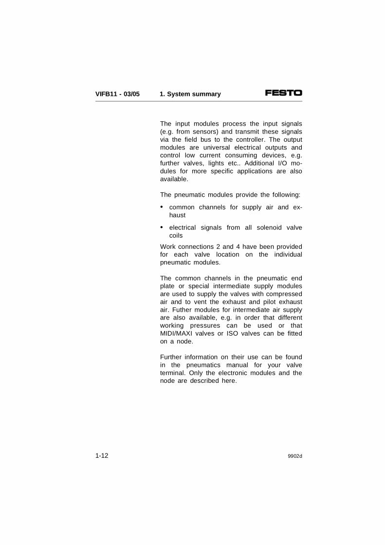
The input modules process the input signals(e.g. from sensors) and transmit these signalsvia the field bus to the controller. The outputmodules are universal electrical outputs andcontrol low current consuming devices, e.g.further valves, lights etc.. Additional I/O mo-dules for more specific applications are alsoavailable.
The pneumatic modules provide the following:
• common channels for supply air and ex-haust
• electrical signals from all solenoid valvecoils
Work connections 2 and 4 have been providedfor each valve location on the individualpneumatic modules.
The common channels in the pneumatic endplate or special intermediate supply modulesare used to supply the valves with compressedair and to vent the exhaust and pilot exhaustair. Futher modules for intermediate air supplyare also available, e.g. in order that differentworking pressures can be used or thatMIDI/MAXI valves or ISO valves can be fittedon a node.
Further information on their use can be foundin the pneumatics manual for your valveterminal. Only the electronic modules and thenode are described here.
VIFB11 - 03/05 1. System summary
1-12 9902d

2. FITTING
VIFB11 - 03/05 2. Fitting
9902d 2-1

Contents
2.1 FITTING THE COMPONENTS 2-3Input/output modules 2-4End plates 2-6Hat rail clamping unit (type 03) 2-8
2.2 TYPE 03: FITTING THE VALVE TERMINAL 2-9Fitting onto a wall (type 03) 2-9Fitting onto a hat rail (type 03) 2-10
2.3 TYPE 05: FITTING THE VALVE TERMINAL 2-12Fitting onto a wall (type 05) 2-12
VIFB11 - 03/05 2. Fitting
2-2 9902d

2.1 FITTING THE COMPONENTS
WARNINGBefore fitting the components, switch off thefollowing:• the compressed air supply• the power supply for the outputs (pin 2)• the power supply for the electronic
components (pin 1)
You can thereby avoid:
• uncontrolled movements of loose tubing
• undesired movements of the connectedactuators
• undefined switching states of the electroniccomponents
CAUTIONThe valve terminal components contain elec-trostatically vulnerable elements.• Do not therefore touch any contact surfaces
on the side plug connectors of the components.
• Please observe the instructions for handling elements liable to damage by electrostaticcharges.
You thereby avoid damaging the valve terminalcomponents.
VIFB11 - 03/05 2. Fitting
9902d 2-3

PLEASE NOTETreat all the modules and valve terminal com-ponents with great care. Pay special attention to the following:• Screw connections must not be distorted or
subjected to mechanical stress.• The screws must fit exactly (otherwise the
threads will be damaged). • The specified torques must be observed.• The modules must be aligned correctly
(IP 65).• The contact surfaces must be clean (avoid
leaks and faulty connections).• The contacts of type 03-MIDI valve solenoid
coils must not be bent (they are not resistant to bending in alternate directions, i.e. theywill break off if bent backwards).
Please observe also the fitting instructions en-closed with modules and components orderedat a later date.
Input/output modules
Before the valve terminal can be extended orconverted, it must first be dismantled.
Dismantling (see also following diagram)
• Remove completely the screws of therelevant modules. The modules are nowheld together only by the plug connectors.
• Pull the modules carefully and without tiltingaway from the plug connectors.
• Replace any seals which are damaged.
VIFB11 - 03/05 2. Fitting
2-4 9902d

Fitting (see also following diagram)
PLEASE NOTE• Modules ordered at a later date should be
placed, where possible, after the lastmodule before the end plate.
• Do not fit more than 12 electronic modules.
Fit the modules as follows:
• Fit a (new) seal on the right-hand contactsurface facing the node.
• Then fit the module as shown in thediagram below.
Seal
Fastening screws max.1 Nm
Fig. 2/1: Fitting the electronic I/O modules
VIFB11 - 03/05 2. Fitting
9902d 2-5

End plates
A left-hand and a right-hand end plate arerequired as a mechanical termination of thevalve terminal. These end plates fulfil thefollowing functions:
• They comply with protection class IP 65.
• They contain contacts for the earth connec-tion.
• They contain openings for fitting onto wallsand onto the hat rail clamping unit.
The right-hand end plate of the ISO terminal isconnected conductively via screw connectorsand ready fitted spring contacts to the manifoldsub-base. It is therefore sufficently earthed.
There are different designs of right-hand endplate for terminal type 03 (MIDI/MAXI). Eachdesign has a ready fitted earth cable.
CAUTIONBefore operating terminal type 03, you mustearth the right-hand end plate by means of theearth cable. This is to avoid interference dueto electromagnetic influences.
VIFB11 - 03/05 2. Fitting
2-6 9902d
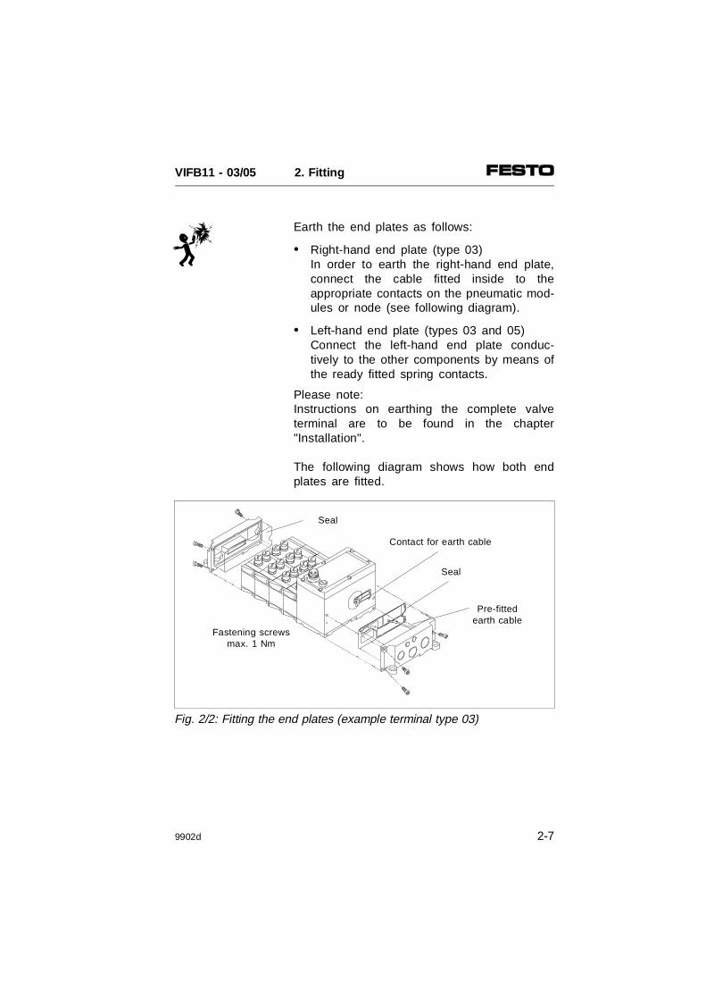
Earth the end plates as follows:
• Right-hand end plate (type 03)In order to earth the right-hand end plate,connect the cable fitted inside to theappropriate contacts on the pneumatic mod-ules or node (see following diagram).
• Left-hand end plate (types 03 and 05) Connect the left-hand end plate conduc-tively to the other components by means ofthe ready fitted spring contacts.
Please note:Instructions on earthing the complete valveterminal are to be found in the chapter"Installation".
The following diagram shows how both endplates are fitted.
Seal
Fastening screwsmax. 1 Nm
Pre-fittedearth cable
Contact for earth cable
Seal
Fig. 2/2: Fitting the end plates (example terminal type 03)
VIFB11 - 03/05 2. Fitting
9902d 2-7

Hat rail clamping unit (type 03)
If the valve terminal is to be fitted onto a hatrail (support rail as per EN 50022), you willrequire a hat rail clamping unit. The hat railclamping unit is fastened to the back of theend plates as shown in the diagram below.
Before fitting ensure that:
• the fastening surfaces are clean (clean with spirit);
• the flat head screws are tightened (6).
After fitting ensure that:
• the levers are secured with a locking screw(7).
1 Self adhesive rubber foot2 Clamping elements3 Left-hand lever *)4 Right-hand lever *)5 O-ring 6 Flat head screw 7 Retaining screw
*) Different lever lengths with MIDI and MAXI
Fig. 2/3: Fitting the hat rail clamping unit
VIFB11 - 03/05 2. Fitting
2-8 9902d

2.2 TYPE 03: FITTING THE VALVE TERMINAL
Fitting onto a wall (type 03)
WARNING In the case of long terminals, use additionalsupport brackets approximately every 200mm. You thereby avoid: • overloading the fastening eyes on the end
plates• the terminal sagging• natural resonances
Proceed as follows: • Calculate the weight of the terminal (weigh or
estimate). General rule:
• Make sure that the fastening surface cansupport this weight.
• Fasten the terminal with four M6 screws asshown below (fitting position as desired). Usespacers if necessary.
MIDI MAXI
Per pneumatic module 800 g 1200 g
per node 1000 g 1000 g
Per electronic module 400 g 400 g
7.6 mm
M6
Fig. 2/4: Fitting terminal type 03 on a wall
VIFB11 - 03/05 2. Fitting
9902d 2-9

Fitting onto a hat rail (type 03)
The terminal is suitable for fitting onto a hatrail (support rail as per EN 50022). For thispurpose there is a guide groove on the rear ofall modules for hanging the terminal on the hatrail.
CAUTION• Fitting onto the hat rail without the hat rail
clamping unit is not permitted.• If the terminal is fitted in a sloping position
or is subjected to vibration, protect it againstslipping and use the screws supplied (7) toprotect it against unintentional loosening/opening.
PLEASE NOTE• If the terminal is fitted in a horizontal position
and is not subjected to vibration, the fasten-ing of the hat rail clamping unit will be suf-ficient without the screws (7).
• If your terminal does not have a hat rail clamping unit, this can be ordered and fittedat a later date.
• Whether MIDI or MAXI clamping units are to be used depends on the end plates(MIDI/MAXI).
Proceed as follows:• Calculate the weight of the terminal (weigh
or estimate). General rule:
MIDI MAXI
Per pneumatic module 800 g 1200 g
Per node 1000 g 1000 g
Per electronic module 400 g 400 g
VIFB11 - 03/05 2. Fitting
2-10 9902d

• Make sure that the fastening surface cansupport this weight.
• Fit a hat rail (support rail as per EN 50022- 35x15; width 35 mm, height 15 mm).
• Fasten the hat rail to the fastening surfaceat least every 100 mm.
• Hang the terminal onto the hat rail. Securethe terminal on both sides against tilting orslipping with the hat rail clamping unit (seediagram below).
• If the terminal is fitted in a sloping positionor is subjected to vibration, use two screws(7) to protect the hat rail clamping unitagainst unintentional loosening/opening.
Hat rail clamping unit Locking screw (7)
Valve terminal type03
Fig. 2/5: Fitting terminal type 03 onto a hat rail
VIFB11 - 03/05 2. Fitting
9902d 2-11
2.3 TYPE 05: FITTING THE VALVE TERMINAL
Fitting onto a wall (type 05)
WARNING In the case of long terminals with several I/Omodules, use additional support brackets ap-proximately every 200 mm.You thereby avoid: • overloading the fastening eyes on the
left-hand end plate• the terminal sagging (I/O side)• natural resonances
• Proceed as follows:
• Calculate the weight of the terminal (weigh orestimate). General rule:
• Make sure that the fastening surface cansupport this weight.
ISOSize 1
ISOSize 2
Sub-base *)- 4 valve locations with
valves- 8 valve locations with
valves- 12 valve locations with
valves
8 kg
14 kg
20 kg
12 kg
20 kg
28 kg
Per node 1 kg 1 kg
Per electronic module 0.4 kg 0.4 kg
*) Components for vertical linking:For weight see Pneumatics Manual P.BE-ISO-05-GB.
VIFB11 - 03/05 2. Fitting
2-12 9902d
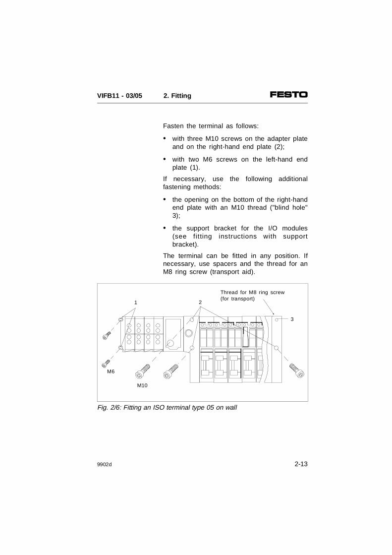
Fasten the terminal as follows:
• with three M10 screws on the adapter plateand on the right-hand end plate (2);
• with two M6 screws on the left-hand endplate (1).
If necessary, use the following additionalfastening methods:
• the opening on the bottom of the right-handend plate with an M10 thread ("blind hole"3);
• the support bracket for the I/O modules(see fitting instructions with supportbracket).
The terminal can be fitted in any position. Ifnecessary, use spacers and the thread for anM8 ring screw (transport aid).
Thread for M8 ring screw(for transport)
M10
3
21
M6
Fig. 2/6: Fitting an ISO terminal type 05 on wall
VIFB11 - 03/05 2. Fitting
9902d 2-13

VIFB11 - 03/05 2. Fitting
2-14 9902d

3. INSTALLATION
VIFB11 - 03/05 3. Installation
9902d 3-1

Contents
3.1 GENERAL CONNECTION TECHNIQUES 3-3Selecting the field bus cable 3-4Selecting the operating voltage cable 3-5Connecting the cables to the plugs/sockets 3-6
3.2 FIELD BUS NODE 3-8Opening and closing the node 3-8Configuring the valve terminal 3-10Setting the station number 3-11Possible station numbers 3-12Setting the field bus baud rate 3-14Setting the field bus protocol 3-15Setting the compatibility (DeviceNet configuration) 3-16
3.2.1 Type 03: Connecting the operating voltages 3-18Calculating the current consumption for type 03 3-21Connection example (type 03) 3-23
3.2.2 Type 05: Connecting the operating voltages 3-25Calculating the current consumption for type 05 3-28Connection example (type 05) 3-30
3.2.3 Connecting the field bus 3-32Connection instructions for Philips DIOS 3-36Connection instr. for Selectron SELECAN 3-37Connection instr. for Allen-Bradley DeviceNet 3-38Connection instructions for Festo DeviceNet (SF 60) 3-38Terminating resistor 3-39
VIFB11 - 03/05 3. Installation
3-2 9902d

3.1 GENERAL CONNECTION TECHNIQUES
WARNINGBefore installation or maintenance work is car-ried out, the following must be switched off: • the compressed air supply• the power supply to the electronic
components (pin 1)• the power supply to the outputs/valves
(pin 2).
You thereby avoid:
• uncontrolled movements of loose tubing
• undesired movements of the connectedactuators
• undefined switching states of the electroniccomponents
VIFB11 - 03/05 3. Installation
9902d 3-3
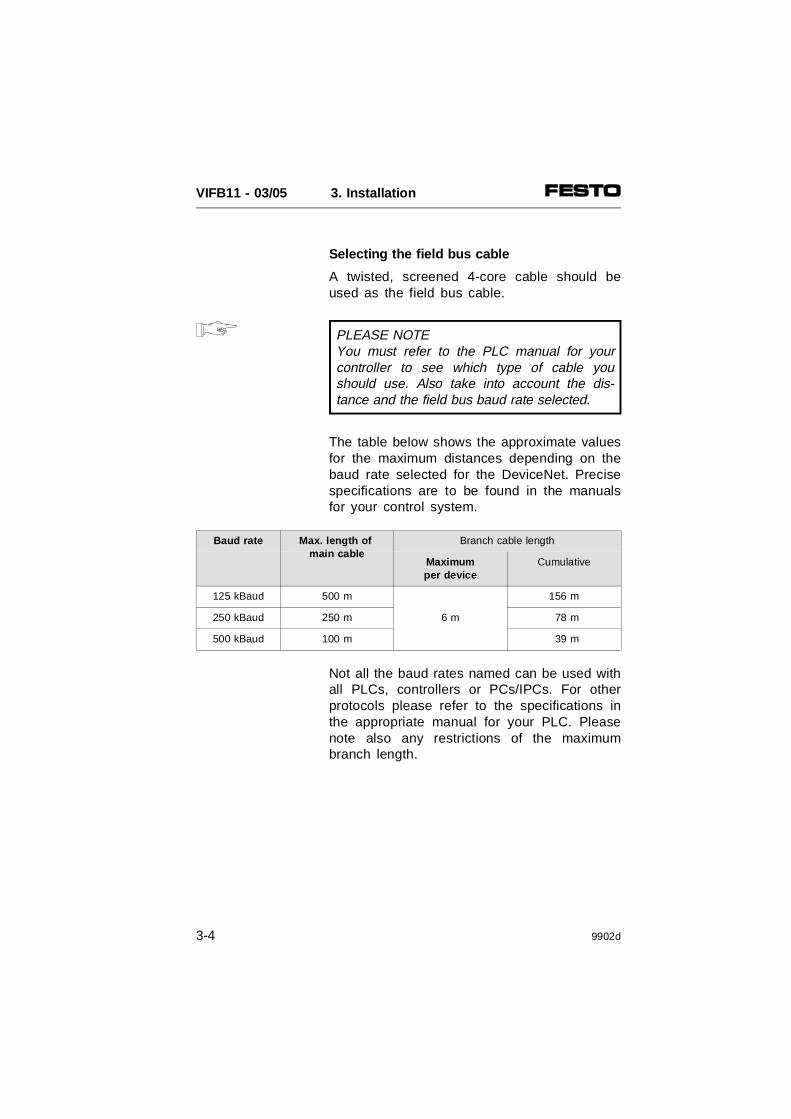
Selecting the field bus cable
A twisted, screened 4-core cable should beused as the field bus cable.
PLEASE NOTEYou must refer to the PLC manual for yourcontroller to see which type of cable youshould use. Also take into account the dis-tance and the field bus baud rate selected.
The table below shows the approximate valuesfor the maximum distances depending on thebaud rate selected for the DeviceNet. Precisespecifications are to be found in the manualsfor your control system.
Baud rate Max. length of main cable
Branch cable length
Maximumper device
Cumulative
125 kBaud 500 m 156 m
250 kBaud 250 m 6 m 78 m
500 kBaud 100 m 39 m
Not all the baud rates named can be used withall PLCs, controllers or PCs/IPCs. For otherprotocols please refer to the specifications inthe appropriate manual for your PLC. Pleasenote also any restrictions of the maximumbranch length.
VIFB11 - 03/05 3. Installation
3-4 9902d
Selecting the operating voltage cable
Several parameters must be taken into con-sideration when the operating voltages areconnected. Further information can be found insubsequent chapters.
• Chapter 3: InstallationSection: "Connecting the
operating voltages"- Calculating the current consumption- Type of power unit- Cable length and cross section
• Chapter 3: InstallationSection: "Connecting the field bus"
- Calculating the current consumption bus interfaces- Cable length and cross section
• Appendix A: Cable length and cross section- Calculating the length and cross section with a table- Calculating with a graph
VIFB11 - 03/05 3. Installation
9902d 3-5
Connecting the cables to the plugs/sockets
CAUTIONThe position of the pins on the plugs is differ-ent from that on the sockets.• The connections of the input and output
modules are in the form of sockets.• The connections of the field bus interface
and those of the operating voltageconnections are in the form of plugs.
The pin assignment can be found in the chapters which follow.
When you have selected suitable cables,connect them according to steps 1...7.
1. Open the plugs/sockets as follows (see diagram):
• Power supply socketInsert the power supply socket intothe operating voltage connection on thevalve terminal. Unscrew the housing of thesocket and remove it. The socket remainsinserted in the operating voltage connection.
• Sensor plug and field bus socketUnscrew the centre knurled nut.
VIFB11 - 03/05 3. Installation
3-6 9902d
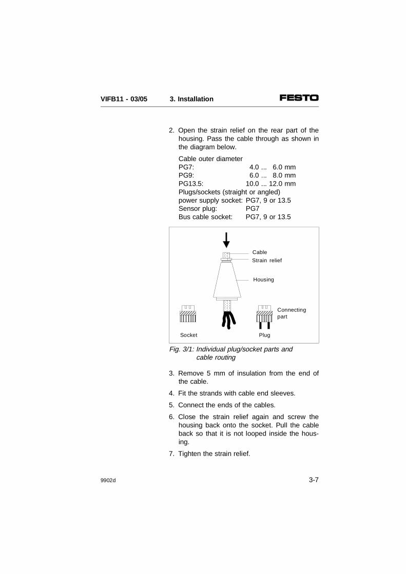
2. Open the strain relief on the rear part of thehousing. Pass the cable through as shown inthe diagram below.
Cable outer diameterPG7: 4.0 ... 6.0 mmPG9: 6.0 ... 8.0 mmPG13.5: 10.0 ... 12.0 mmPlugs/sockets (straight or angled)power supply socket: PG7, 9 or 13.5Sensor plug: PG7Bus cable socket: PG7, 9 or 13.5
3. Remove 5 mm of insulation from the end ofthe cable.
4. Fit the strands with cable end sleeves.
5. Connect the ends of the cables.
6. Close the strain relief again and screw thehousing back onto the socket. Pull the cableback so that it is not looped inside the hous-ing.
7. Tighten the strain relief.
AAAAAAAAAAAAAAA
AAAAAAAAAAAA
AAAAAAAAAAAA
AAAAAAAAAAAAA
AAAAAAAA
AAAAAAAAA
AAAAAAAAAAAA
AAAAAAAAAAAAA
AAAAAAAA
AAAAAAAAA Connecting
part
Cable
Housing
Strain relief
PlugSocket
Fig. 3/1: Individual plug/socket parts andcable routing
VIFB11 - 03/05 3. Installation
9902d 3-7
3.2 FIELD BUS NODE
Opening and closing the node
WARNINGBefore installation or maintenance work is car-ried out, the following must be switched off: • the compressed air supply• the operating voltage supply to the
electronic components (pin 1).• the operating voltage supply to the
outputs/valves (pin 2).
You thereby avoid:
• uncontrolled movements of loose tubing
• undesired movements of the connectedactuators
• undefined switching states of the electroniccomponents.
CAUTIONThe valve terminal node contains electrostati-cally vulnerable components.• Do not therefore touch any components.• Observe the regulations for dealing with
electrostatically vulnerable components.
In this way the electronic components of thenode will not be damaged.
VIFB11 - 03/05 3. Installation
3-8 9902d

The following connecting and display elementsare to be found on the cover of the node.
PLEASE NOTEThe cover is connected to the internal printedcircuit boards by means of the operating volt-age cable. It cannot, therefore, be removedcompletely.
• OpeningUnscrew and remove the 6 Philips screwsin the cover. Carefully lift up the cover. Donot damage the cable through mechanicalstress.
• ClosingReplace the cover. Place the operatingvoltage cables back into the housing so thatthey are not clamped. Tighten the Philipsscrews in the cover in diagonally oppositesequence.
AAAAAAAAA
POWER
AAAAAAAAA
ERRORAAAAAAAAAMOD/NET
AAAAAAAAA
BUS
BUS
POWER
STATUS
Red LED
Plug forfield buscable
Fuse foroperating voltage ofinputs
Operating voltageconnection
Green LED Green LEDGreen LED
Fig. 3/2: Cover of node
VIFB11 - 03/05 3. Installation
9902d 3-9

Configuring the valve terminal
There are four printed circuit boards in thenode. Board 2 contains two LEDs and a plugfor the field bus cable; board 3 contains twoLEDs and switches for setting the configura-tion.
0
891234
67
5
AAAAAA
1234
0
891234
67
5
AAAAAA
AAAAAA
AAAA
AAAA
AAAAAAAAAAAAAAAAAAAAAAAAA
AAAAAAAA
AAAAAAAA
AAAAAAAAAAAA
AAAAA
AAAA
AAAAAA
AAAAAAAAAA
Red LED
Plug forfield buscables
Addressselector switch(station number)
Screening
Board 2 Board 3
Flat plug foroperating voltageconnection
Board 1
Board 4
Baud rateProtocol Compatibility withDN configuration
Green LEDGreen LEDGreen LED
Fig. 3/3: Connecting, display and operating elements of the node
VIFB11 - 03/05 3. Installation
3-10 9902d
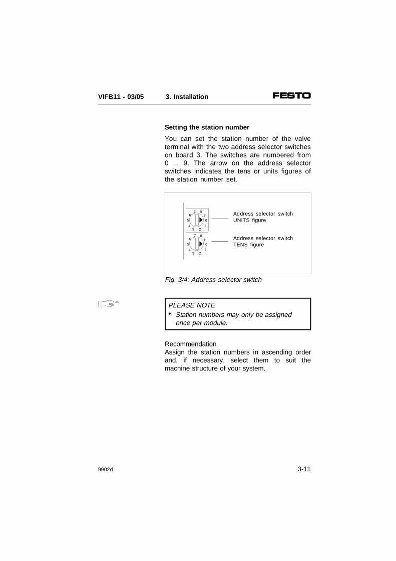
Setting the station number
You can set the station number of the valveterminal with the two address selector switcheson board 3. The switches are numbered from0 ... 9. The arrow on the address selectorswitches indicates the tens or units figures ofthe station number set.
PLEASE NOTE• Station numbers may only be assigned
once per module.
RecommendationAssign the station numbers in ascending orderand, if necessary, select them to suit themachine structure of your system.
6
5
2
7 8
0
13
4
9
6
5
2
7 8
0
13
4
9 Address selector switchTENS figure
Address selector switchUNITS figure
Fig. 3/4: Address selector switch
VIFB11 - 03/05 3. Installation
9902d 3-11

Possible station numbers
Proceed as follows:
1. Switch off the operating voltage.
2. Assign an unused station number to the valveterminal.
3. Use a screwdriver to set the arrow of therelevant address selector switch to the unitsor tens figure of the desired station number.
Example
PLC Address designation Station numbers
Allen-Bradley andFesto DeviceNet
Node 0; ...; 63
Philips DIOS Node no./network module 1; ...; 29
Selectron SELECAN Node module 1; ...; 29
Fig. 3/5: Station numbers
65
2
7 8
01
34
9
65
2
7 8
01
34
9
65
2
7 8
01
34
9
65
2
7 8
01
34
9
Setting with field bus address: 05
Setting with field bus address: 38
UNITS
TENS
UNITS
TENS
Fig. 3/6: Function of the address selector switch
VIFB11 - 03/05 3. Installation
3-12 9902d

Besides the address selector switch there isalso a DIL switch in the node. The followingfunctions can be set on this DIL switch:
• the field bus baud rate
• the field bus protocol
• compatibility with DN configuration.
The DIL switch consists of four switch el-ements. These are numbered from 1 to 4. Theposition ON is marked.
0
891234
67
5
AAAA
0
891234
67
5
AAAA
AAAAAAAAAAAAAAAAAAAA
AAAAAA
AAAAAA
AAAAAAAAAAAA
AA
AAAA
AAAAAA
1234ON
1234ON
Field bus baud rate
Compatibility with DN configuration
Field bus protocol
Fig. 3/7: Position of the DIL switch
VIFB11 - 03/05 3. Installation
9902d 3-13

Setting the field bus baud rate
PLEASE NOTESet the field bus baud rate of the valve termi-nal so that it corresponds to that set on thefield bus module/interface of the master.Please note that the same DIL switch setting(1,2) results in different baud rates for the dif-ferent protocols.
WARNINGSelecan protocol.If you use the PMC 40 as master, set thebaud rate higher than 20 kBaud. In this wayyou will avoid the values being switched onand off in an uncontrolled manner.
Manufac-turer
Protocol Field bus baud rate [kBaud]
Allen-Bradleyand Festo
DeviceNet 125 kBaud 250 kBaud 500 kBaud ---------------
Philips DIOS 20 kBaud 100 kBaud 500 kBaud 1000 kBaud
Selectron Selecan 20 kBaudnot withPMC 40
100 kBaud 500 kBaud 1000 kBaud
DIL switchsettings
Fig. 3/8: Setting the field bus baud rate
12
34
1234
12
34
1234
1234
ON
VIFB11 - 03/05 3. Installation
3-14 9902d
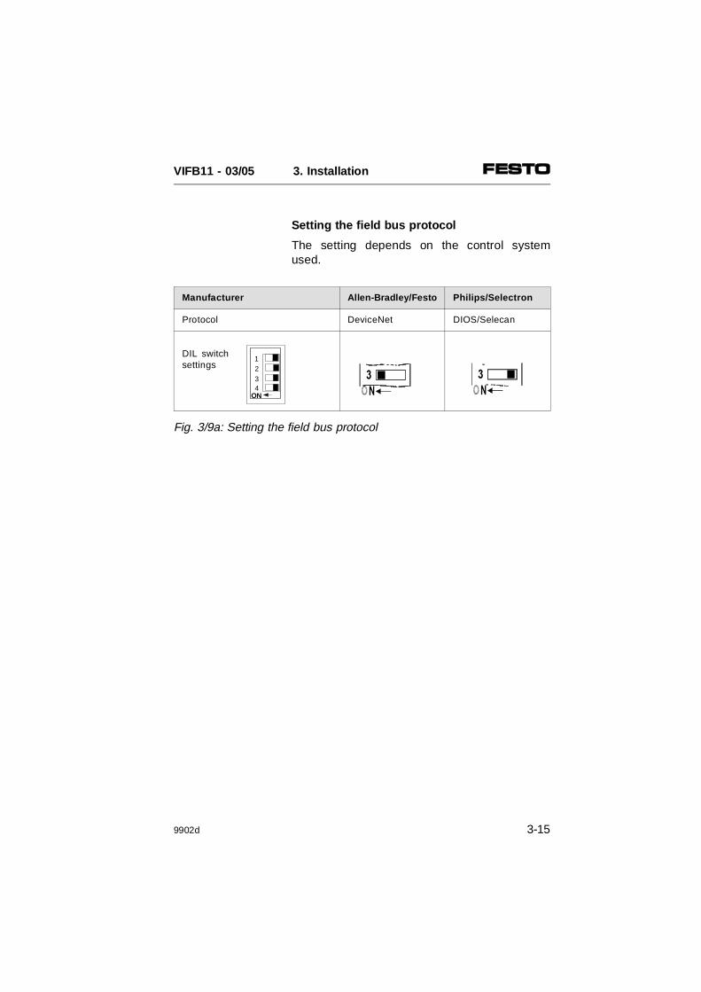
Setting the field bus protocol
The setting depends on the control systemused.
Manufacturer Allen-Bradley/Festo P hilips/Selectron
Protocol DeviceNet DIOS/Selecan
DIL switchsettings
Fig. 3/9a: Setting the field bus protocol
1234
ON
VIFB11 - 03/05 3. Installation
9902d 3-15
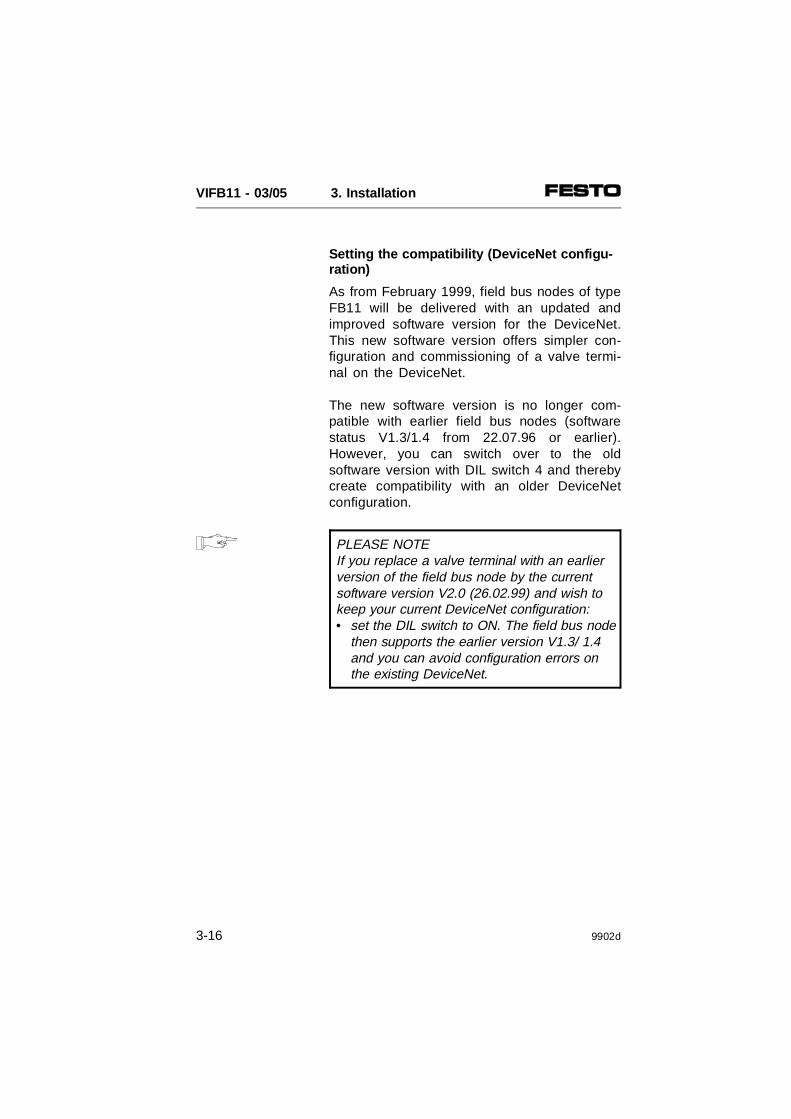
Setting the compatibility (DeviceNet configu-ration)
As from February 1999, field bus nodes of typeFB11 will be delivered with an updated andimproved software version for the DeviceNet.This new software version offers simpler con-figuration and commissioning of a valve termi-nal on the DeviceNet.
The new software version is no longer com-patible with earlier field bus nodes (softwarestatus V1.3/1.4 from 22.07.96 or earlier).However, you can switch over to the oldsoftware version with DIL switch 4 and therebycreate compatibility with an older DeviceNetconfiguration.
PLEASE NOTE If you replace a valve terminal with an earlierversion of the field bus node by the currentsoftware version V2.0 (26.02.99) and wish tokeep your current DeviceNet configuration:• set the DIL switch to ON. The field bus node
then supports the earlier version V1.3/ 1.4and you can avoid configuration errors on the existing DeviceNet.
VIFB11 - 03/05 3. Installation
3-16 9902d
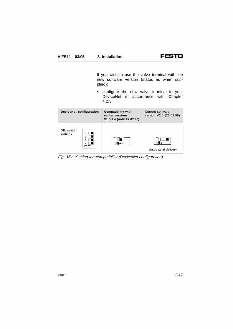
If you wish to use the valve terminal with thenew software version (status as when sup-plied):
• configure the new valve terminal in yourDeviceNet in accordance with Chapter4.2.3.
DeviceNet configuration Compatibility withearlier versionsV1.3/1.4 (until 22.07.96)
Current softwareversion V2.0 (26.02.99)
DIL switchsettings
status as at delivery
Fig. 3/9b: Setting the compatibility (DeviceNet configuration)
1234
ON
VIFB11 - 03/05 3. Installation
9902d 3-17

3.2.1 Type 03: Connecting the operating voltages
WARNING Use only power units which guarantee reliableisolation of the operating voltages as per IEC742/EN 60742/VDE 0551 with at least 4 kVisolation resistance (protected extra low volt-age, PELV). Switch power packs are permittedif they guarantee reliable isolation in accord-ance with EN 60950/VDE 0805.
Remark:Protection against electric shock (protectionagainst direct and indirect contact) is guaran-teed on Festo valve terminals by the use ofPELV power units in accordance with EN60204-1/IEC 204. Safety transformers with theadjacent designation must be used for sup-plying PELV networks. The valve terminalsmust be earthed in order to ensure theirfunction (e.g. EMC).
CAUTION The power supply to the outputs/valves (pin 2)must be separately fused externally with max.10 A. The external fuse prevents the valve ter-minal from being damaged in the event of ashort circuit.
VIFB11 - 03/05 3. Installation
3-18 9902d
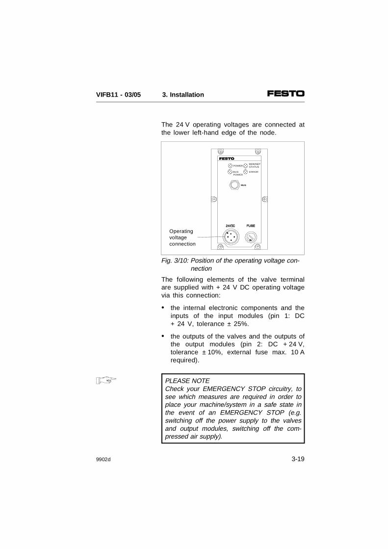
The 24 V operating voltages are connected atthe lower left-hand edge of the node.
The following elements of the valve terminalare supplied with + 24 V DC operating voltagevia this connection:
• the internal electronic components and theinputs of the input modules (pin 1: DC+ 24 V, tolerance ± 25%.
• the outputs of the valves and the outputs ofthe output modules (pin 2: DC + 24 V,tolerance ± 10%, external fuse max. 10 Arequired).
PLEASE NOTECheck your EMERGENCY STOP circuitry, tosee which measures are required in order toplace your machine/system in a safe state inthe event of an EMERGENCY STOP (e.g.switching off the power supply to the valvesand output modules, switching off the com-pressed air supply).
AAAAAAPOWER
AAAAAAAAA
ERROR
AAAAAAMOD/NET
AAAAAAAAA
BUS
BUS
POWER
STATUS
Operatingvoltageconnection
Fig. 3/10: Position of the operating voltage con- nection
VIFB11 - 03/05 3. Installation
9902d 3-19

Power unit
PLEASE NOTEIf there is a common voltage supply for pin 1(electronic components and inputs) and pin 2(outputs/valves) the lower tolerance of ±10%for both circuits must be observed.
Check the 24 V operating voltage for theoutputs whilst your system is operating. Pleaseensure that this voltage lies within the per-mitted tolerances even during full operation.
Recommendation
• Use a closed loop power unit.
• Calculate the complete current consumptionin accordance with the following table andthen select a suitable power unit and cablecross section.
• Avoid long distances between the powerunit and the terminal. Calculate the per-mitted distance in accordance with Appen-dix A.The following general rule applies to type03:
Supply voltage Cable crosssection
Distance
Pin 1 = 2.2 APin 2 = 10 A
VO = 24 V
1.5 mm2 ≤ 8 m
2.5 mm2 ≤ 14 m
VIFB11 - 03/05 3. Installation
3-20 9902d

Calculating the current consumption fortype 03
The table below shows how to calculate the totalcurrent consumption for terminal type 03. Thevalues quoted have been rounded up. If othervalves or modules are used, you should consultthe appropriate technical specifications for theircurrent consumption.
Current consumption of electronic compo-nents on node type 03 and inputs(pin 1, 24 V ± 25 %)
Node
Number of simultaneously occupied sensor inputs: ____x0.010 A
Sensor supplies: ____x_____ A(see manufacturer specifications)
+
+
Current consumption of electroniccomponents on the nodeand inputs (pin 1) max. 2.2 A
=
Current consumption of outputs type 03(pin 2, 24 V ± 10 %)
Number of MIDI valve coils (simultaneously under power): ____ x 0.055 A
Number of MAXI valve coils (simultaneously under power): ____ x 0.100 A
Number of simultaneously activated electrical outputs: _____x 0.010 A
Load current of simultaneously activated electrical outputs: _____x_____ A
+
+
+
+
Current consumption outputs (pin 2) max. 10 A = +
Total current consumption ofvalve terminal type 03 =
∑ A
∑ A
∑ A
∑ A
∑ A
∑ A
∑ A
∑ A
0.200 A
∑ A
A
∑ A
Fig. 3/11: Calculating the total current consumption type 03
VIFB11 - 03/05 3. Installation
9902d 3-21

The following diagram shows the pin assign-ment of the operating voltage connection.
Potential equalization
The valve terminal has two earth connectionsfor potential equalization:
• on the operating voltage connection (pin 4incoming contact)
• on the left-hand end plate (M4 thread)
PLEASE NOTE• Always connect the earth potential to pin 4
of the operating voltage connection.• Connect the earth cable of the left-hand end
plate to the earth potential with low im-pedance (short cable with large sectionalarea).
• By means of low impedance connections,make sure that the housing of the valve terminal and the earth connection at pin 4have the same potential and that there are no equalizing currents.
You can thereby avoid interference due toelectromagnetic influences.
24 Vsupply to valves andoutputs
0 VEarth connection
24 Vsupply toelectroniccomponents and inputs
Fig. 3/12: Pin assignment of the operatingvoltage connection (type 03)
VIFB11 - 03/05 3. Installation
3-22 9902d
Connection example (type 03)
The following diagram shows the connection ofa common 24V supply for pins 1 and 2. Pleasenote that:
• the supply to the outputs/valves must beprotected against short circuit/overload withan external fuse max. 10 A;
• the supply to the electronic components andinputs must be protected against shortcircuit/overload with an external 3.15 A fuse(recommendation);
• the common tolerance of 24 V DC ± 10%must be observed;
• both pins for potential equalization must beconnected and compensating currents mustbe prevented;
• the operating voltage can be switched offseparately at pin 2 (valves/electrical out-puts).
VIFB11 - 03/05 3. Installation
9902d 3-23

10 A
external fuses
DC 24V± 10%
AC 24 V 3,15 A
Fuse forinputs/sensors (2 A)
0 V
Potential equalization
Earth cableconnection pin 4designed for 12 A
Load voltagecan beswitched offseparately
Bild 3/13: Example – connecting a common 24 V supply and potentilal compensation (type 03)
VIFB11 - 03/05 3. Installation
3-24 9902d

3.2.2 Type 05: Connecting the operating voltages
WARNING Use only power units which guarantee reliableisolation of the operating voltages as per IEC742/EN 60742/VDE 0551 with at least 4 kVisolation resistance (protected extra low volt-age, PELV). Switch power packs are permittedif they guarantee reliable isolation in accord-ance with EN 60950/VDE 0805.
Remark:Protection against electric shock (protectionagainst direct and indirect contact) is guaran-teed on Festo valve terminals by the use ofPELV power units in accordance with EN60204-1/IEC 204. Safety transformers with theadjacent designation must be used for sup-plying PELV networks. The valve terminalsmust be earthed in order to ensure theirfunction (e.g. EMC).
CAUTIONThe operating voltage supply to the outputs(pin 2) must be fused externally with max.10 A. The external fuse prevents the terminalfrom being damaged in the event of a shortcircuit.
The 24 V operating voltages are connected onthe adapter plate between the node and thevalves. The node and the I/O modules aresupplied with current via the adapter cable.
VIFB11 - 03/05 3. Installation
9902d 3-25

The following elements of valve terminal type05 are supplied with +24 V DC operatingvoltage via this connection:
• the internal electronic components and theinputs of the inputs modules (pin 1: + 24 VDC, tolerance 25%, external fuse max. 3.15A recommended).
• the outputs of the valves and the outputs ofthe output modules (pin 2: + 24 V DC,tolerance 10%, external fuse max. 10 Aslow blowing required).
PLEASE NOTECheck your EMERGENCY STOP circuitry, tosee which measures are required in order toplace your machine/system in a safe state inthe event of an EMERGENCY STOP (e.g.switching off the power supply to the valvesand output modules, switching off the com-pressed air supply).
Operatingvoltageconnection
type 05
Fuses forvalves 4 Aslow blowing *)
Adapter cable
*) Do not switch on more than 12 valves at the same time, otherwise the valvefuse will blow
Fig. 3/14: Position of the operating voltage connection type 05
VIFB11 - 03/05 3. Installation
3-26 9902d

Power unit
PLEASE NOTEIf there is a common voltage supply for pin 1(electronic components and inputs) and pin 2(outputs/valves), the lower tolerance of 10%for both circuits must be observed.
Check the 24 V operating voltage of theoutputs whilst your system is operating. Pleaseensure that this voltage lies within the per-mitted tolerances even during full operation.
Recommendation
• Use a closed loop power unit.
• Calculate the complete current consumptionin accordance with the following table andthen select a suitable power unit andsuitable cable sectional area.
• Avoid long distances between the powerunit and the terminal. Calculate the per-mitted distance in accordance with Appen-dix A.
The following general rule applies to type 05:
Supplymax.*)
Cablesectional area
Distance
Pin 1 = 2.2 A 1.5 mm2 ≤ 8 m
Pin 2 = 10 A 2.5 mm2 ≤ 14 m
VO = 24 V
*) Please observe the maximum total current consumption (pins 1 and 2) of max. 12.2 A.
VIFB11 - 03/05 3. Installation
9902d 3-27

Calculating the current consumption fortype 05
The table below shows how to calculate thetotal current consumption for ISO terminal type05. The values quoted have been rounded up.If other valves or modules are used, youshould consult the appropriate technical speci-fications for their current consumption.
Current consumption of electroniccomponents node type 05 and inputs(pin 1, 24 V ± 25 %)
Node
Number of simultaneously occupied digital sensor inputs: ____ x 0.010 A
Sensor supplies: ____ x _____ A(see manufacturer specifications)
+
+
Current consumption of electronic componentsnode and inputs (pin 1) max. 2.2 A =
Current consumption of outputs type 05(pin 2, 24 V ± 10 %)
Number of pilot valve solenoids (max. 12 solenoids simultaneously under power): ___ x 0.300 A
Number of simultaneously activated electrical outputs: ___ x 0.010 A
+
+
Load current of simultaneously activated electrical outputs: ___ x _____A
Current consumption of outputs (pin 2) max.10.0 A
= +
Total current consumption of valve terminal type 05 =
∑ A
∑ A
∑ A
∑ A
∑ A
∑ A
∑ A
∑ A
0.200 A
A
+
∑ A
Fig. 3/15: Calculating the total current consumption type 05
VIFB11 - 03/05 3. Installation
3-28 9902d

The following diagram shows the pin assign-ment of the operating voltage connection onthe adapter plate.
Potential equalization
The valve terminal has two earth connectionsfor potential equalization:
• on the operating voltage connection (pin 4 incoming contact)
• on the left-hand end plate (M4 thread).
PLEASE NOTE• Always connect the earth potential to pin 4
of the operating voltage connection.• Connect the earth cable of the left-hand end
plate to the earth potential with low im-pedance (short cable with large sectionalarea).
• By means of low impedance connections,make sure that the housing of the valve terminal and the earth connection at pin 4have the same potential and that there are no equalizing currents.
You can thereby avoid interference due toelectromagnetic influences.
24 Vsupply to valves andoutputs
0 VEarth connection
24 Vsupply toelectroniccomponents and inputs
Fig. 3/16: Pin assignment of operating voltage connection (type 05)
VIFB11 - 03/05 3. Installation
9902d 3-29

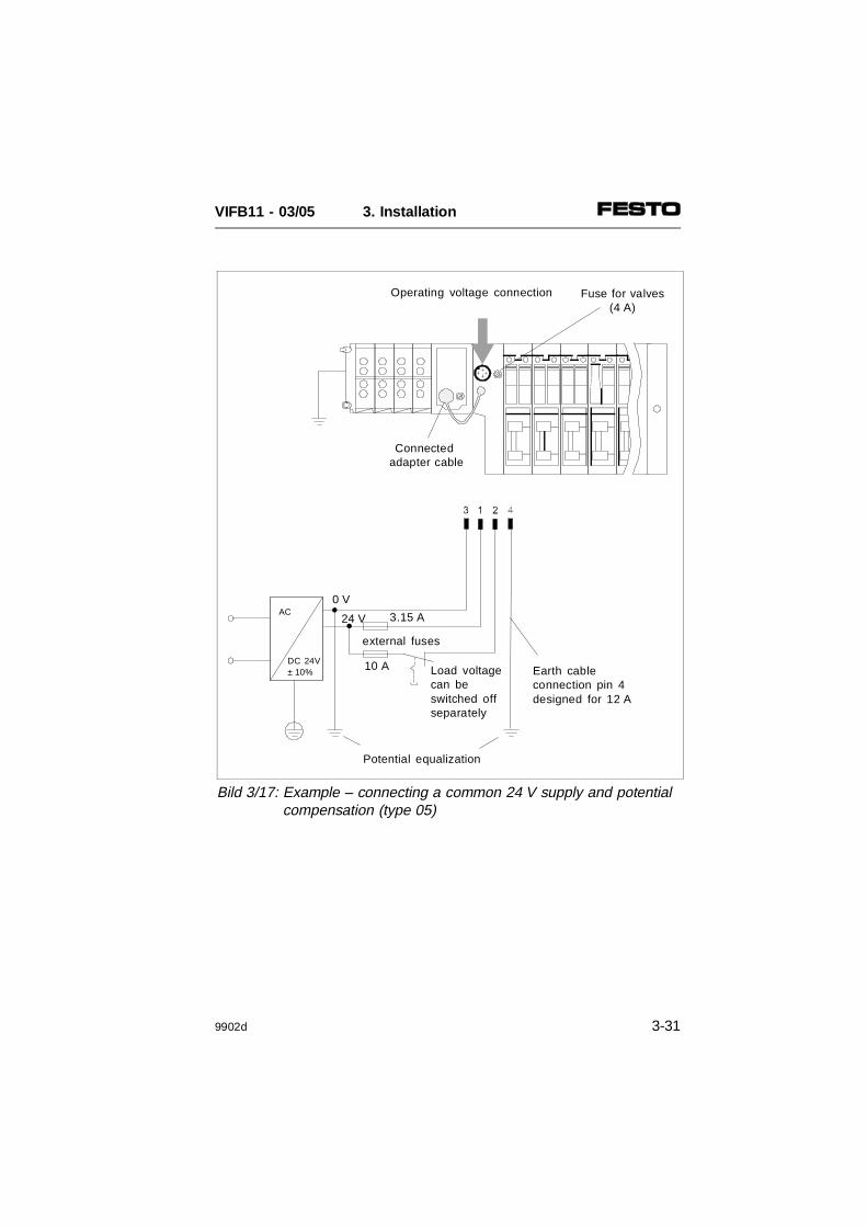
Connection example (type 05)
The following diagram shows the connection ofa common 24V supply for pins 1 and 2. Pleasenote that:
• the outputs must be protected against shortcircuit/overload with an external slow-blow-ing fuse of max. 10 A;
• the electronic components and inputs mustbe protected against short circuit/overloadwith an external 3.15 A fuse (recommenda-tion);
• the sensors must be additionally protectedwith the (2 A) fuse fitted;
• the valves must be additionally protectedwith the 4 A slow-blowing fuse fitted;
• the common tolerance of 24 V DC ± 10%must be observed;
• the node must be supplied with power viathe adapter cable;
• both pins for potential equalization must beconnected and compensating currents mustbe prevented;
• the operating voltage can be switched offseparately at pin 2 (valves/electrical out-puts).
VIFB11 - 03/05 3. Installation
3-30 9902d
Potential equalization
Load voltagecan beswitched offseparately
external fuses
10 A
AC
DC 24V± 10%
0 V
3.15 A24 V
Operating voltage connection
Connected adapter cable
Fuse for valves(4 A)
Earth cableconnection pin 4designed for 12 A
Bild 3/17: Example – connecting a common 24 V supply and potential compensation (type 05)
VIFB11 - 03/05 3. Installation
9902d 3-31
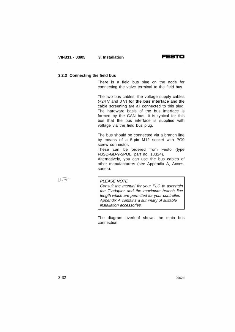
3.2.3 Connecting the field bus
There is a field bus plug on the node forconnecting the valve terminal to the field bus.
The two bus cables, the voltage supply cables(+24 V and 0 V) for the bus interface and thecable screening are all connected to this plug.The hardware basis of the bus interface isformed by the CAN bus. It is typical for thisbus that the bus interface is supplied withvoltage via the field bus plug.
The bus should be connected via a branch lineby means of a 5-pin M12 socket with PG9screw connector.These can be ordered from Festo (typeFBSD-GD-9-5POL, part no. 18324).Alternatively, you can use the bus cables ofother manufacturers (see Appendix A, Acces-sories).
PLEASE NOTEConsult the manual for your PLC to ascertainthe T-adapter and the maximum branch linelength which are permitted for your controller.Appendix A contains a summary of suitable installation accessories.
The diagram overleaf shows the main busconnection.
VIFB11 - 03/05 3. Installation
3-32 9902d

AAAA
AAAAAAAAAAAAAAA
AAAAAA
AAAA
AAAAAAAAAAAA
AAAA
Field busVoltage supply forbus interface
Branch line
T-adapter
Screening
+24 V
0 V
Bus
Fig. 3/18: Structure of bus interface
VIFB11 - 03/05 3. Installation
9902d 3-33

Current consumption of all bus interfaces
Number of FESTO valve terminalsconnected_______ * 50 mA
Current consumption of theremaining field bus interfaces
Current consumption of sensor inputs/sensor supply via the bus
Total current consumption ofall bus interfaces
Avoid long distances between the bus voltagesupply and the bus slaves.
If necessary, calculate the permitted distance(see also Appendix A).
PLEASE NOTEBus slaves of different manufacturers have dif-ferent tolerances in respect of the interfacesupply. Take this into consideration whenplanning the bus length. The following applies to FESTO valveterminals: Vmax = 25V Vmin = 11.5V
∑ A
∑ A
∑ A
∑ A
VIFB11 - 03/05 3. Installation
3-34 9902d

CAUTION• Please observe the correct polarity when
connecting the field bus interface. • Connect the screening.
The diagram below shows the pin assignmentof the field bus interface. Connect the field buscables to the terminals of the bus cable socket.Please observe also the connection instruc-tions in the other diagrams as well as theinstructions in the PLC manual for yourcontroller.
Data +
+24V busGND bus
Screening
1MΩ220 nF
internalRC network
Node housing
Data -
Fig. 3/19: Pin assignment of the field businterface
VIFB11 - 03/05 3. Installation
9902d 3-35

Connection instructions for Philips DIOS
PLEASE NOTEYou must check the connection assignment ofthe module in the PLC manual for your con-troller.
Connect the field bus cable of your controlsystem to the field bus interface of the valveterminal as follows:
PLC plug/pin assignment Valve terminal PINassignment of the field bus interface
View PIN Signal designation
nc = Not connected
Fig. 3/20: Pin assignment Philips DIOS
5
4
3
2
1
9
8
7
6
123456789
Bus -GND
Bus +
Data -nc
GND Bus
+24V Bus
Data +
Pin 5
Pin 1
Pin 3
Pin 2
Pin 4
+24V
0V
Screening
VIFB11 - 03/05 3. Installation
3-36 9902d
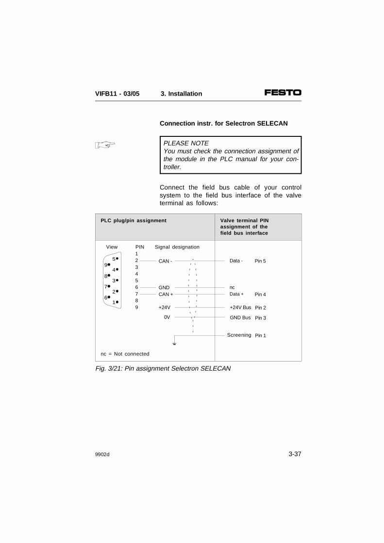
Connection instr. for Selectron SELECAN
PLEASE NOTEYou must check the connection assignment ofthe module in the PLC manual for your con-troller.
Connect the field bus cable of your controlsystem to the field bus interface of the valveterminal as follows:
PLC plug/pin assignment Valve terminal PINassignment of the field bus interface
View PIN Signal designation
nc = Not connected
Fig. 3/21: Pin assignment Selectron SELECAN
5
4
3
2
1
9
8
7
6
123456789
CAN -
CAN +
Data -
GND Bus
+24V Bus
Data +
Pin 5
Pin 1
Pin 3
Pin 2
Pin 4
+24V
0V
GND nc
Screening
VIFB11 - 03/05 3. Installation
9902d 3-37

Connection instr. for Allen-Bradley DeviceNet
PLEASE NOTEYou must check the connection assignment ofthe module in the PLC manual for your con-troller.
Connect the field bus cable of your controlsystem to the field bus interface of the valveterminal as follows:
Connection instructions for Festo DeviceNet(SF 60)
The pin assignment on the Festo DeviceNetmaster SF 60 and on the valve terminal withFB11 are identical (see Fig. 3/19).
PLC plug/pin assignment Valve terminal PIN assignment ofthe field bus interface
View Signal designation
Data + PIN 4+24V bus PIN 2
Data - PIN 5Screening PIN 1
GND bus PIN 3
WHITERED
BLUEBARE
BLACK
Fig. 3/22: Pin assignment Allen-Bradley DeviceNet
VIFB11 - 03/05 3. Installation
3-38 9902d

Terminating resistor
If the valve terminal to be connected is at theend of the field bus line, a terminating resistormust be fitted. Adaption is necessary.
Recommendation:Install the required terminating resistor inaccordance with the recommendations of theODVA (Open DeviceNet Vendor Association)or of Allen-Bradley (see manual for yourcontroller). The diagram below shows anexample.
AAA
AAAAAA
AAAAAA
AAAAAA
AAAAAAAAA
Power unit for 24 V supply
Power Tap for 24 V supply
DeviceBox Tap T-Port Tap
Terminatingresistor
PC with DNinterface converterand DN managersoftware
1770-KFDor1784-PCD
Series 9000Photoelectric sensor
Festo SF 60 DeviceNet scanner
Terminating resistor
Fig. 3/23a: Example – terminating resistor connected to theT-distributor (T-port tap)
VIFB11 - 03/05 3. Installation
9902d 3-39

You can also install the required terminatingresistor (120 Ohm, 0.25 Watt) economically inthe socket of the field bus cable. To do thisproceed as follows:
1. Connect the wires of the resistor together withthose of the field bus cable between thewires Data + (pin 4) and Data - (pin 5) of thebus cable socket.
PLEASE NOTETo guarantee reliable contact, we recommendthat the wires of the resistor and those of thebus cable be crimped together in common endsleeves.
2. Fit the bus cable socket to the field bus plug.
Fig. 3/23b: Pin assignment of the field bus interface
VIFB11 - 03/05 3. Installation
3-40 9902d

4. COMMISSIONING
VIFB11 - 03/05 4. Commissioning
9902d 4-1

Contents
4.1 BASIC PRINCIPLES OF CONFIGURATION AND ADDRESSING 4-5General 4-5Switching on the operating voltage 4-6Calculating the configuration data 4-7Calculating the number of inputs/outputs 4-9Address assignment of the valve terminal 4-11General information on type 03 and type 05 4-11Basic rule 1 4-12Basic rule 2 4-15Basic rule 3 4-15Address assignment after extension/conversion 4-16
4.2 BASIC PRINCIPLES OF COMMISSIONING AND DIAGNOSIS 4-18
4.2.1 Philips Dios 4-18General 4-18Configuration 4-20Example 4-21Addressing the inputs/outputs 4-22Program example 4-24Diagnosis 4-25Diagnosis via DLC 100/200 4-25Diagnosis via the user program 4-26Diagnostic objects of the system 4-26Status bits 4-27
VIFB11 - 03/05 4. Commissioning
4-2 9902d

4.2.2 SELECTRON SELECAN 4-29General 4-29Configuration 4-31Addressing the inputs/outputs 4-32Program example 4-34Diagnosis 4-35Diagnosis via the PMC 40 4-35Diagnosis via the user program 4-35System flags SM11.01 - SM11.29 4-35System flags SM12.01 - SM12.29 4-36Status bits 4-36
4.2.3 Allen-Bradley DeviceNet 4-39General 4-39Festo SF 60 as DeviceNet master 4-41CD ROM "Utilities" 4-41Extending the EDS library 4-42Installing the EDS file (recommended variant) 4-43Extending the network with a valve terminal 4-44Configuring the scanner 4-47Entering the number of I/Os 4-48Assignment and transmission mode 4-51Scanner 1771-SDN (PLC 5 series) 4-55Scanner 1747-SDN (SF 60 and SLC 500 series) 4-56Example 1: Scanner 1771-SDN (PLC 5 series) 4-57Example 2: Scanner 1747-SDN(SLC 500 series) 4-59Explicit message 4-61Diagnosis 4-62Diagnosis via DeviceNet scanner 4-62Diagnosis via user program 4-62Device failure table 4-62Status bits 4-63
VIFB11 - 03/05 4. Commissioning
9902d 4-3

VIFB11 - 03/05 4. Commissioning
4-4 9902d

4.1 BASIC PRINCIPLES OF CONFIGURATION AND ADDRESSING
General
Before commissioning or programming, youshould first compile a configuration list of allthe connected field bus slaves. On the basis ofthis list you can:
• make a comparison between the ACTUALand NOMINAL configurations in order toascertain if there are any incorrect connec-tions.
• access these specifications during the syn-tax check of a program, in order to avoidaddressing errors.
The valve terminal must be configured veryaccurately, since different configuration specifi-cations may be required for each terminal dueto the modular structure. Please observe herealso the specifications in the followingsections.
PLEASE NOTEThe accompanying CD ROM contains product-specific icons and some EDS files for Device-Net for the Festo valve terminals.• Read the File "Readme.txt" on the CD ROM,
if applicable, for a brief summary of the contents of the CD ROM.
VIFB11 - 03/05 4. Commissioning
9902d 4-5

Switching on the operating voltage
PLEASE NOTEObserve also the switching-on instructions inthe PLC manual for your controller.
When the controller is switched on, it automat-ically carries out a comparison between theNOMINAL and ACTUAL configurations. Thefollowing points are important for the configura-tion:
• The specifications on configuration must becomplete and correct.
• The power supplies to the PLC and to thefield bus slaves must be switched on eithersimultaneously or in the sequence specifiedbelow.
Please observe also the following points whenswitching on the power supplies:
• Common supply. If the control system andall the field bus slaves have a commonpower supply, the supply should beswitched on with a common central powerunit or switch.
• Separate supply. If the control system andthe field bus slaves have separate powersupplies, the supplies should be switchedon in the following sequence:
1. first the field bus slaves2. then the control system.
VIFB11 - 03/05 4. Commissioning
4-6 9902d

Calculating the configuration data
Before configuring, calculate the exact numberof inputs/outputs available. A modular valveterminal consists of a number of I/Os whichdiffers depending on the type of valve terminal.
PLEASE NOTE• The terminal makes available four status
bits for diagnosis via the field bus. These are always assigned automatically within the terminal when there are input modules.
• The status bits occupy four additionalinput addresses.
VIFB11 - 03/05 4. Commissioning
9902d 4-7
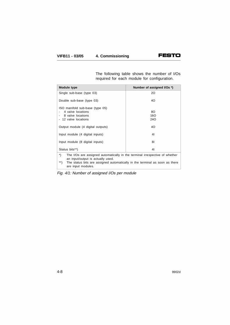
The following table shows the number of I/Osrequired for each module for configuration.
Module type Number of assigned I/Os *)
Single sub-base (type 03)
Double sub-base (type 03)
ISO manifold sub-base (type 05)- 4 valve locations- 8 valve locations- 12 valve locations
Output module (4 digital outputs)
Input module (4 digital inputs)
Input module (8 digital inputs)
Status bits**)
2O
4O
8O16O24O
4O
4I
8I
4I
*) The I/Os are assigned automatically in the terminal irrespective of whetheran input/output is actually used.
**) The status bits are assigned automatically in the terminal as soon as thereare input modules.
Fig. 4/1: Number of assigned I/Os per module
VIFB11 - 03/05 4. Commissioning
4-8 9902d

Calculating the number of inputs/outputs
Copy this table for further calculations andascertain the number of inputs/outputs.
Table for calculating the inputs/outputs type 03
INPUTS
1. Number of 4-input modules ______ ⋅ 4
2. Number of 8-input modules ______ ⋅ 8
3. The 4 status bits are assigned internally automatically by the terminal. They must be treated like inputs and added to the intermediate sum.
+
+
Total sum of inputs to be configured =
OUTPUTS
4. Number of single sub-bases type 03 _______ ⋅ 2
5. Number of double sub-bases type 03 _______ ⋅ 4 +
Intermediate sum of 4.+ 5.
6. Check whether sum of 4 + 5 can be divided without remainder. This check is necessary because of the 4-bit orientated internal addressing of the terminal.Different cases:
a) If divisible by 4 without remaindercontinue with point 7.
b) If not round up (+ 2 outputs)
7. Number of electrical 4-output modules _______ ⋅ 4
=
+
+
Total sum of outputs to be configured =
Σ E
Σ E
4E
Σ E
Σ A
Σ A
Σ A
Σ A
Σ A
Fig. 4/2: Calculating the number of inputs/outputs type 03
2A
VIFB11 - 03/05 4. Commissioning
9902d 4-9
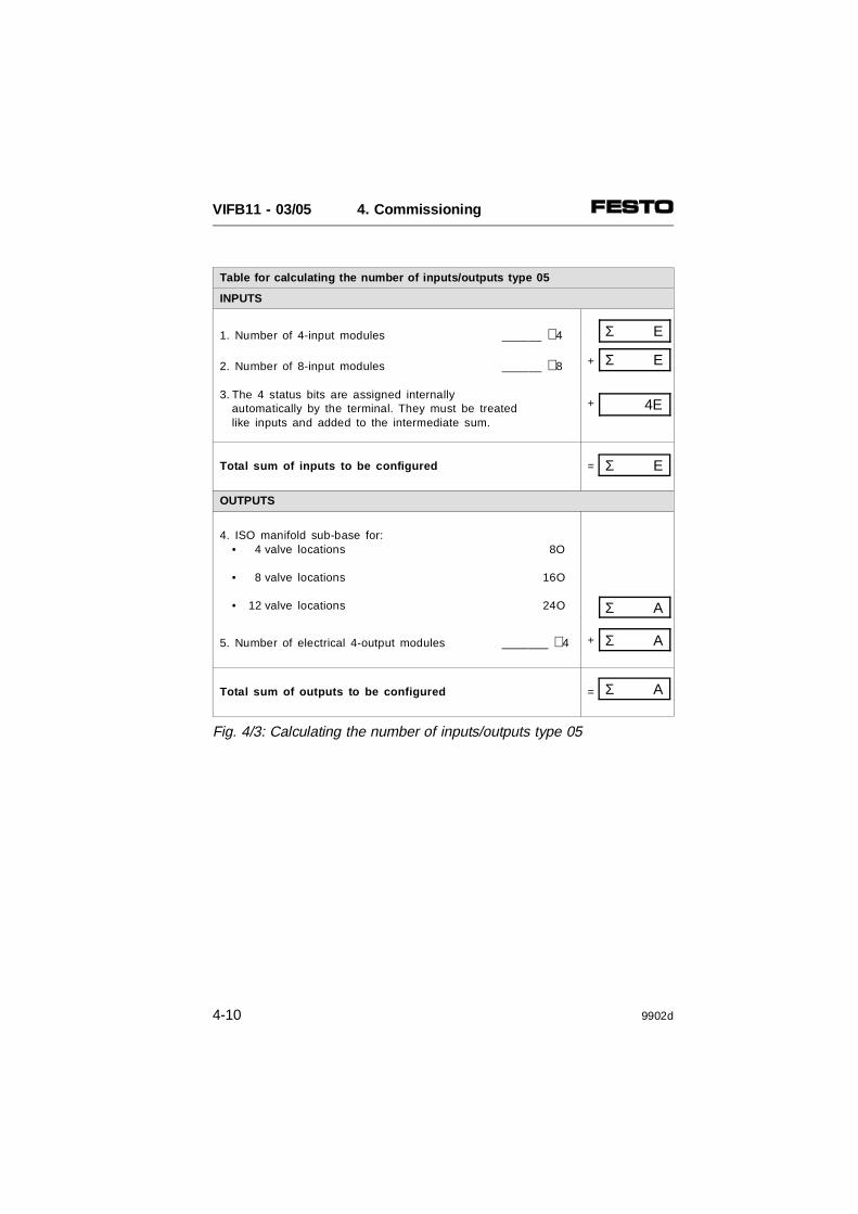
Table for calculating the number of inputs/outputs type 05
INPUTS
1. Number of 4-input modules ______ ⋅ 4
2. Number of 8-input modules ______ ⋅ 8
3. The 4 status bits are assigned internally automatically by the terminal. They must be treated like inputs and added to the intermediate sum.
+
+
Total sum of inputs to be configured =
OUTPUTS
4. ISO manifold sub-base for:• 4 valve locations 8O
• 8 valve locations 16O
• 12 valve locations 24O
5. Number of electrical 4-output modules _______ ⋅ 4 +
Total sum of outputs to be configured =
Σ E
Σ E
4E
Σ E
Σ A
Σ A
Σ A
Fig. 4/3: Calculating the number of inputs/outputs type 05
VIFB11 - 03/05 4. Commissioning
4-10 9902d
Address assignment of the valve terminal
General information on type 03 and type 05
The address assignment of a modular valveterminal depends on the equipment fitted onthe terminal. A distinction must be madebetween the following equipment fitted:
• valves and digital I/O modules
• valves only
• digital I/O modules only
The basic rules described overleaf apply to theaddress assignment of these fitting variants.
PLEASE NOTEIf two addresses are assigned for one valvelocation, the following applies:• Lower-value address ⇒
pilot solenoid 14• Higher-value address ⇒
pilot solenoid 12
VIFB11 - 03/05 4. Commissioning
9902d 4-11

Basic rule 1
With mixed fitting, consideration is given tothe address assignment of the valves, the digi-tal I/O modules and the status bits.1. Outputs:
The address assignment of the outputsdoes not depend on the inputs.
1.1 Address assignment of the valves:• Addresses should be assigned in
ascending order without gaps.• Counting begins on the node
from left to right . • Single sub-bases always occupy two addr.• Double sub-bases always occupy four addr.• ISO valve locations always occupy two addr.• Maximum 26 valve solenoid coils
can be addressed.1.2 Rounding up to 4 bits, different cases:
a) If the number of valve addresses canbe divided by 4 without remainder,continue with point 1.3.
b) If the number of valve addresses cannotbe divided by 4 without remainder, thenumber must be rounded up to 4 bitsbecause of the 4-bit orientatedaddressing. The 2 bits thus rounded upcannot be used.
1.3 Address assignment of the output modules: The digital outputs are addressed after the (rounded up 4-bit) addresses of the valves.• Addresses should be assigned in
ascending order without gaps.• Counting begins on the node
from right to left .• Counting on the individual modules
is from top to bottom.• Digital output modules always
occupy 4 addresses.
VIFB11 - 03/05 4. Commissioning
4-12 9902d
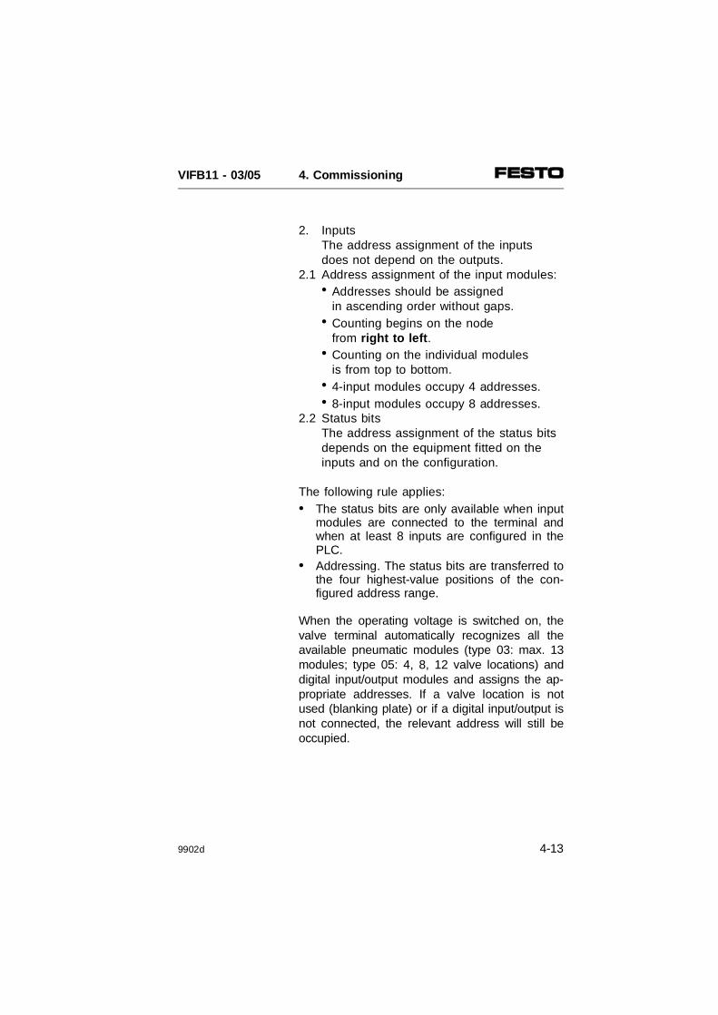
2. InputsThe address assignment of the inputs does not depend on the outputs.
2.1 Address assignment of the input modules:• Addresses should be assigned
in ascending order without gaps.• Counting begins on the node
from right to left .• Counting on the individual modules
is from top to bottom.• 4-input modules occupy 4 addresses.• 8-input modules occupy 8 addresses.
2.2 Status bitsThe address assignment of the status bits depends on the equipment fitted on theinputs and on the configuration.
The following rule applies:• The status bits are only available when input
modules are connected to the terminal andwhen at least 8 inputs are configured in thePLC.
• Addressing. The status bits are transferred tothe four highest-value positions of the con-figured address range.
When the operating voltage is switched on, thevalve terminal automatically recognizes all theavailable pneumatic modules (type 03: max. 13modules; type 05: 4, 8, 12 valve locations) anddigital input/output modules and assigns the ap-propriate addresses. If a valve location is notused (blanking plate) or if a digital input/output isnot connected, the relevant address will still beoccupied.
VIFB11 - 03/05 4. Commissioning
9902d 4-13

The diagram below shows the address assign-ment with mixed fitting.
Remarks on the diagram• If single solenoid valves are fitted onto
double sub-bases, four addresses will bereserved for valve solenoid coils; the higheraddress in each case then remains unused(see address 3).
• If unused valve locations are fitted withblanking plates, the addresses will still be oc-cupied (see addresses 12, 13).
• Due to the 4-bit orientated addressing of themodular valve terminal, the address of thelast valve location is always rounded up tofour full bits (unless the equipment fitted al-ready uses the four full bits). This means thattwo addresses cannot be used (see ad-dresses 14, 15).
8 0 20 16
9 2 21 171
3
10
11
4567
22
23
18
19
23
45
67
0 1 89
1011 13 15
1412
4-in
put
mo
dule
8-in
put
mod
ule
4-o
utpu
t m
odu
le
8-ou
tput
mod
ule
Sin
gle
su
b-ba
se
Dou
ble
sub
-bas
e
Ro
und
up
Dou
ble
su
b-ba
se
Dou
ble
su
b-ba
sePlease note:If a valve location occupies two addresses, the following applies:• Lower-value address ⇒ pilot solenoid 14• Higher-value address ⇒ pilot solenoid 12
Fig. 4/4: Address assignment of a valve terminal with digital I/Os (example type 03)
VIFB11 - 03/05 4. Commissioning
4-14 9902d

Basic rule 2
If only valves are used, the address assignmentwill always be as described in basic rule 1.
PLEASE NOTE• Maximum 26 valve solenoid coils
can be addressed. • There is no rounding up of the last
two positions on the valve side.• Valve terminals without input modules
do not require a configuration for inputs.The status bits are not therefore available.
Basic rule 3
If only electrical I/Os are used, the addressassignment will always be as described inbasic rule 1.
PLEASE NOTE• Counting begins immediately
to the left of the node.• There is no rounding up of the last
two positions on the valve side.
VIFB11 - 03/05 4. Commissioning
9902d 4-15

Address assignment after extension/conversion
A special feature of the modular valve terminalis its flexibility. If the demands placed on themachine change, then the equipment fitted onthe terminal can also be modified.
CAUTIONIf extensions or conversions are made to theterminal at a later stage, this may result in ashifting of the input/output addresses. This applies in the following cases:• if one or more pneumatic modules
is/are fitted/removed at a later stage(type 03).
• if a pneumatic module with single valves is replaced by a new module with double valves or vice versa (type 03).
• if additional input/output modules are inserted between the node and existinginput/output modules.
• if existing 4-input modules are replaced by 8-input modules or vice versa.
If the configuration of the inputs is changed,the addresses of the status bits will always beshifted.
VIFB11 - 03/05 4. Commissioning
4-16 9902d

The diagram below shows the modifications tothe address assignment if the standard fittingin the previous diagram is extended.
Please note:Air supply modules and intermediate air supplymodules do not occupy any addresses.
8 0 24 20
9 2 25 211
3
10
11
4567
26
27
22
23
18 191415
1617
23
45
67
0 1 89
1011 13
12
4-in
put
mod
ule
8-in
put
mod
ule
4-ou
tput
mod
ule
4-ou
tput
mo
dule
Sin
gle
sub
-bas
e
Dou
ble
sub-
base
Do
not
roun
d up
Do
uble
sub
-bas
e
Dou
ble
sub
-bas
e
Dou
ble
su
b-ba
se
Sin
gle
su
b-ba
se
SU
PP
LY
Please note:If a valve location occupies two addresses, the following applies:• Lower-value address ⇒ pilot solenoid 14• Higher-value address ⇒ pilot solenoid 12
Fig. 4/5: Address assignment of a valve terminal after extension/conversion
VIFB11 - 03/05 4. Commissioning
9902d 4-17

4.2 BASIC PRINCIPLES OF COMMISSIONING AND DIAGNOSIS
4.2.1 Philips Dios
General
If the modular valve terminal is used with thePhilips DIOS, the following points must beobserved:
• The addresses of all recognized networkmodules, including those of the valve termi-nal, are assigned in ascending order with-out gaps.
• The input and output addresses are as-signed independently of each other.
PLEASE NOTEThe sum of the input bytes and output bytesper valve terminal must not exceed 8 bytes.Use a DLC interface with software status asfrom V1.1.
VIFB11 - 03/05 4. Commissioning
4-18 9902d

Possible input bytes
0 0 0 0 0 0 0 0 0
1 1 1 1 1 1 1 1 8
2 2 2 2 2 2 2 7 7
3 3 3 3 3 3 6 6 6
4 4 4 4 4 5 5 5 5
5 5 5 5 4 4 4 4 4
6 6 6 3 3 3 3 3 3
7 7 2 2 2 2 2 2 2
8 1 1 1 1 1 1 1 1
0 0 0 0 0 0 0 0 0
Possible output bytes
Please consult your manual for the controllerfor calculating the total transmission time. Theinternal processing time of the FESTO valveterminal is < 1 ms.
VIFB11 - 03/05 4. Commissioning
9902d 4-19
Configuration
Calculate first the number of input and outputbytes.
PLEASE NOTEThe number of inputs per valve terminal willincrease by 4 status bits if input modules arefitted. The 4 inputs supply status informationwith which internal error messages are trans-mitted in coded form to the DLC 100/200.
You can compare the calculated number ofbus slaves and the calculated number of inputand output bytes with the number calculatedby the DLC 100/200.
When you press the "CONF" key, the followingwill appear in the seven segment display:
• the number of recognized network modules(e.g. valve terminals)
• the number of input bytes
• the number of output bytes
Enter the calculated number of input andoutput bytes (+ if necessary with reserves forextensions) in the mask "Resource hardware -input/output modules".
VIFB11 - 03/05 4. Commissioning
4-20 9902d

Example
Valve terminal #3: 4 input bytes, 4 output bytesValve terminal #4: 3 input bytes, 2 output bytesValve terminal #5: 2 input bytes, 2 output bytesValve terminal #6: 3 input bytes, 2 output bytes
When you press the "CONF" key, the followingfigures will appear in the seven segmentdisplay of the DLC 100/200.
• 4 (=number of recognized network modules)
• 12 (=number of input bytes)
• 10 (=number of output bytes)
If the values shown agree with the calculatedvalues, you can transfer these to your project.In the example below, the number of I/O byteshas been rounded up, in order that theaddresses are not shifted if extensions aremade at a later date.
Fig. 4/6: I/O configuration DLC 100
VIFB11 - 03/05 4. Commissioning
9902d 4-21

Addressing the inputs/outputs
In the previous example, the I/O addresses ofthe valve terminal begin with input/outputaddress 4. As already mentioned, the I/O bytesare assigned to the valve terminals in ascend-ing order without gaps, separately for inputsand outputs.
The diagram below shows the assignment ofthe valve terminal I/Os to the I/O addressrange of the Philips P8 for the valve terminalconfiguration shown in Fig. 4/8.
AAAAAAAAAAAAAAAAAAAAAAAAAAAAAAAAAAAAAAAAAAAAAAAAAAAAAAAAAAAAAAAAAAAAAAAAAAAAAAAAAAAAAAAAAAAAAAAAAAAAAAAAAAAAAAAAAAAAAAAA
AAAAAAAAAAAAAAAAAAAAAAAAAAAAAAAAAAAAAAAAAAAAAAAAAAAAAAAAAAAAAAAAAAAAAAAAAAAAAAAAAAAAAAAAAAAAAAAAAAAAAAAAAAAAAAAAAAAAAAAA
AAAAAAAAAAAAAAAAAAAAAAAAAAAAAAAAAAAAAAAAAAAAAAAAAAAAAAAAAAAAAAAAAAAAAAAAAAAAAAAAAAAAAAAAAAAAAAAAAAAAAAAAAAAAAAAAAAAAAAAA
AAAAAAAAAAAAAAAAAAAAAAAAAAAAAAAAAAAAAAAAAAAAAAAAAAAAAAAAAAAAAAAAAAAAAAAAAAAAAAAAAAAAAAAAAAAAAAAAAAAAAAAAAAAAAAAAAAAAAAAA
AAAAAAAAAAAAAAAAAAAAAAAAAAAAAAAAAAAAAAAAAAAAAAAAAAAAAAAAAAAAAAAAAAAAAAAAAAAAAAAAAAAAAAAAAAAAAAAAAAAAAAAAAAAAAAAAAAAAAAAAAAAAAAAAAAAAAAAAAAAAAAAA
AAAAAAAAAAAAAAAAAAAAAAAAAAAAAAAAAAAAAAAAAAAAAAAAAAAAAAAAAAAAAAAAAAAAAAAAAAAAAAAAAAAAAAAAAAAAAAAAAAAAAAAAAAAAAAAAAAAAAAAAAAAAAAAAAAAAAAAAAAAAAAAA
AAAAAAAAAAAAAAAAAAAAAAAAAAAAAAAAAAAAAAAAAAAAAAAAAAAAAAAAAAAAAAAAAAAAAAAAAAAAAAAAAAAAAAAAAAAAAAAAAAAAAAAAAAAAAAAAAAAAAAAAAAAAAAAAAAAAAAAAAAAAAAAA
AAAAAAAAAAAAAAAAAAAAAAAAAAAAAAAAAAAAAAAAAAAAAAAAAAAAAAAAAAAAAAAAAAAAAAAAAAAAAAAAAAAAAAAAAAAAAAAAAAAAAAAAAAAAAAAAAAAAAAAAAAAAAAAAAAAAAAAAAAAAAAAA
QB0.0QB0.1QB1.0QB1.1QB2.0QB2.1QB3.0QB3.1QB4.0QB4.1QB5.0QB5.1QB6.0QB6.1QB7.0QB7.1QB8.0QB8.1QB9.0QB9.1QB10.0QB10.1QB11.0QB11.1QB12.0QB12.1
AAAAAAAAAAAAAAAAAAAAAAAAAAAAAAAAAAAAAAAAAAAAAAAA
AAAAAAAAAAAAAAAAAAAAAAAAAAAAAAAAAAAAAAAAAAAAAAAA
AAAAAAAAAAAAAAAAAAAAAAAAAAAAAAAAAAAAAAAAAAAAAAAA
AAAAAAAAAAAAAAAAAAAAAAAAAAAAAAAAAAAAAAAAAAAAAAAA
AAAAAAAAAAAAAAAAAAAAAAAAAAAA
AAAAAAAAAAAAAAAAAAAAAAAAAAAA
AAAAAAAAAAAAAAAAAAAAAAAAAAAA
AAAAAAAAAAAAAAAAAAAAA
AAAAAAAAAAAAAAAAAAAAAAAAAAAAAAAAAAAAAAAA
AAAAAAAAAAAAAAAAAAAAAAAAAAAAAAAAAAAAAAAA
AAAAAAAAAAAAAAAAAAAAAAAAAAAAAAAAAAAAAAAA
AAAAAAAAAAAAAAAAAAAAAAAAAAAAAAAAAAAAAAAAAAAA
AAAAAAAAAAAAAAAAAAAAAAAAAAAAAAAAAAAAAAAAAAAA
AAAAAAAAAAAAAAAAAAAAAAAAAAAAAAAAAAAAAAAAAAAAAAAA
AAAAAAAAAAAAAAAAAAAAAAAAAAAAAAAAAAAAAAAAAAAAAAAA
AAAAAAAAAAAAAAAAAAAAAAAAAAAAAAAAAAAA
AAAAAAAAAAAAAAAAAAAAAAAAAAAA
AAAAAAAAAAAAAAAAAAAAAAAAAAAA
AAAAAAAAAAAAAAAAAAAAAAAAAAAA
AAAAAAAAAAAAAAAAAAAAAAAAAAAA
AAAAAAAAAAAAAAAAAAAAAAAAAAAA
AAAAAAAAAAAAAAAAAAAAAAAAAAAA
AAAAAAAAAAAAAAAAAAAAAAAAAAAA
AAAAAAAAAAAAAAAAAAAAA
AAAAAAAAAAAAAAAAAAAAAAAAAAAAAAAAAAAAAAAA
AAAAAAAAAAAAAAAAAAAAAAAAAAAAAAAAAAAAAAAA
AAAAAAAAAAAAAAAAAAAAAAAAAAAAAAAAAAAAAAAA
AAAAAAAAAAAAAAAAAAAAAAAAAAAAAAAAAAAAAAAA
AAAAAAAAAAAAAAAAAAAAAAAAAAAA
AAAAAAAAAAAAAAAAAAAAAAAAAAAA
AAAAAAAAAAAAAAAAAAAAAAAAAAAA
AAAAAAAAAAAAAAAAAAAAA
IB0.0IB0.1IB1.0IB1.1IB2.0IB2.1IB3.0IB3.1IB4.0IB4.1IB5.0IB5.1IB6.0IB6.1IB7.0IB7.1IB8.0IB8.1IB9.0IB9.1IB10.0IB10.1IB11.0IB11.1IB12.0IB12.1
OutputsInputs
Valve terminal #42 bytes
Valve terminal #43 bytes
Address range of valveterminals
I/O address range Philips P8
Con
figu
red
I/O
add
ress
ran
geD
LC 1
00/2
00
Valve terminal #52 Bytes
Valve terminal #52 bytes
Valve terminal #62 bytes
Valve terminal #63 bytes
Valve terminal #34 bytes
Valve terminal #34 bytes
Fig. 4/7: I/O configuration DLC 100
VIFB11 - 03/05 4. Commissioning
4-22 9902d

The following diagrams show the assignmentof the inputs/outputs to the valve terminals #4and #5 in the previous example.
Valve terminal #4: Input byte 6.0, 6.1, 7.0 Output byte 6.0, 6.1Valve terminal #5: Input byte 7.1, 8.0 Output byte 7.0, 7.1
Q6.
0
Q6.
1
Q6.
3Q
6.2
Q6.
5Q
6.4
Q6.
7Q
6.6
Q6.
9Q
6.8
Q6.
11Q
6.10
Q6.
12Q
6.13
Q6.
14Q
6.15
I6.0
I6.1
I6.3
I6.4
I6.2
I6.5
I6.6
I6.7
I6.8
I6.9
I6.1
1I6
.12
I6.1
0I6
.13
I6.1
4I6
.15
I7.0
I7.1
I7.2
I7.3
Q7.
0
Q7.
1
Q7.
3Q
7.2
Q7.
5Q
7.4
Q7.
7Q
7.6
I7.8
I7.9
I7.1
1I7
.12
I7.1
0I7
.13
I7.1
4I7
.15
I8.0
I8.1
I8.2
I8.3
Q7.
8Q
7.9
Q7.
10Q
7.11
Q7.
12Q
7.13
Q7.
14Q
7.15
A4E8E4
0
2
4
6
1
3
5
7
A4
12
13
14
15
8
9
10
11
8
9
10
11
E8E8E4
8
10
12
14
9
11
13
15
16
17
18
19
#4
#5
A4
0
2
4
6
1
3
5
7
12
13
14
15
23
45
67
0 1 89 10
11
23
45 6
70 1
Fig. 4/8: Example – addressing
VIFB11 - 03/05 4. Commissioning
9902d 4-23

Program example
Addressing a valve terminal with 20 inputs(+ 4 status bits) and 16 outputs (12 valvecoils, 4 electrical outputs).
Network module number 41st. input address 6.01st. output address 6.0
Fig. 4/9: Example – program extract
E4 E8 A4E8
8
10
12
14
9
11
13
15
16
17
18
19
0
2
4
6
1
3
5
7
12
13
14
15
23
45
67
0 1 89 10
11
VIFB11 - 03/05 4. Commissioning
4-24 9902d

Diagnosis
The following types of bus diagnosis areavailable within the DIOS system:
• Diagnosis via DLC 100/200
• Diagnosis via the user program
Diagnosis via DLC 100/200
Bus errors are shown on the two sevensegment displays of the DLC 100/200:
The FESTO valve terminals behave on theDIOS in respect of the diagnosis like theequivalent Philips DIOS modules. If there is ashort circuit on the output modules, the LED"LOAD" will light up. Special error messagesare not shown. The errors L1-L4 and E1-E6are also generated by the valve terminalswhen there is an error.
AAAAAAAAAAAAAAAAAAAAAAAAAAAAAAAAAAAAAAAAAAAAAAAAAAAAAAAAAAAAAAAAAAAAAAAAAAAAAAAA
AAAAAAAAAAAAAAAAAAAAAAAAAAAAAAAAAAAAAAAAAAAAAAAAAAAAAAAAAAAAAAAAAAAAAAAAAAAAAAAA
AAAAAAAAAAAAAAAAAAAAAAAAAAAAAAAAAAAAAAAAAAAAAAAAAAAAAAAAAAAAAAAAAAAAAAAAAAAAAAAA
AAAAAAAAAAAAAAAAAAAAAAAAAAAAAAAAAAAAAAAAAAAAAAAAAAAAAAAAAAAAAAAAAAAAAAAAAAAAAAAA
AAAAAAAAAAAAAAAAAAAAAAAAAAAAAAAAAAAAAAAAAAAAAAAAAAAAAAAAAAAA
DLC 100P8 compact line
LOAD
OK
ERR.
Fig. 4/10: Seven segment displays DLC 100
VIFB11 - 03/05 4. Commissioning
9902d 4-25

Diagnosis via the user program
With diagnosis via the user program, you canuse one of the following:
• the diagnostic objects of the system
• the status bits of the valve terminals
Diagnostic objects of the system
The diagram below shows the diagnosticobjects of the system. The diagnostic object"_CONF" will be set to logic 1 if there is nobus configuration.
Fig. 4/11: Summary of diagnostic objects
VIFB11 - 03/05 4. Commissioning
4-26 9902d

Status bits
The status bits signalize internal errors to thevalve terminal. The following errors are recog-nized:
• undervoltage at the valves/outputs< 21.6 V
• undervoltage at the valves/outputs< 10 V
• short circuit/overload on at least one electri-cal output
• undervoltage at sensor supply< 10 V
Further details can be found in Chapter 5"Diagnosis and error treatment" (Chapter 5.4Status bits).
The status bits are treated and transferred likeinputs. They always occupy the highest-valueaddresses of the available address range. Ifthe inputs of the input addresses thereunderare not used, the valve terminal will set themto "logic zero."
The following table shows the addresses of thestatus bits in the address range of a valveterminal, depending on the equipment fitted onthe valve terminal.
VIFB11 - 03/05 4. Commissioning
9902d 4-27

Number of input bytes
Available address range
Addressesof the status bits
None No address range for inputs No status bits available
1 input byte 0 ... 7 4, 5, 6, 7
2 input byte 0 ... 15 12 ... 15
3 input byte 0 ... 23 20 ... 23
4 input byte 0 ... 31 28 ... 31
5 input byte 0 ... 39 36 ... 39
6 input byte 0 ... 47 44 ... 47
7 input byte 0 ... 55 52 ... 55
8 input byte 0 ... 63 60 ... 63
The following example shows the assignmentof the inputs/outputs and the status bits.
Q7.
0
Q7.
1
Q7.
3Q
7.2
Q7.
5Q
7.4
Q7.
7Q
7.6
I7.8
I7.9
I7.1
1I7
.12
I7.1
0I7
.13
I7.1
4I7
.15
I8.0
I8.1
I8.2
I8.3
Q7.
8Q
7.9
Q7.
10Q
7.11
Q7.
12Q
7.13
Q7.
14Q
7.15
#5
I8.4
I8.5
I8.6
I8.7
E4 E8 A4 A4
8
9
10
11
0
2
4
6
1
3
5
7
12
13
14
15
8
9
10
11
23
45 6
70 1
Addresses ofthe status bits
Fig. 4/12: Example - addressing status bits
VIFB11 - 03/05 4. Commissioning
4-28 9902d

4.2.2 SELECTRON SELECAN
General
If the modular valve terminal is used with theSelectron SELECAN, the following points mustbe observed:
• The I/O addresses of all recognized nodecomponents, including the valve terminals,are assigned depending on the node num-ber set (station number).
• The input and output addresses are as-signed independently of each other.
• The node numbers may be assigned asdesired in the range 1-29.
• Each node number must only be assignedonce.
PLEASE NOTEThe sum of the input and output bytes pervalve terminal must not exceed 8 bytes.
VIFB11 - 03/05 4. Commissioning
9902d 4-29

Possible input bytes
0 0 0 0 0 0 0 0 0
1 1 1 1 1 1 1 1 8
2 2 2 2 2 2 2 7 7
3 3 3 3 3 3 6 6 6
4 4 4 4 4 5 5 5 5
5 5 5 5 4 4 4 4 4
6 6 6 3 3 3 3 3 3
7 7 2 2 2 2 2 2 2
8 1 1 1 1 1 1 1 1
0 0 0 0 0 0 0 0 0
Possible output bytes
Please consult the manual for your controllerfor calculating the total transmission time. Theinternal processing time of the FESTO valveterminal is < 1 ms.
Ma
x. p
ossi
ble
outp
ut b
ytes
Ma
x. p
ossi
ble
inpu
t b
ytes
VIFB11 - 03/05 4. Commissioning
4-30 9902d

Configuration
A special configuration is not required foroperating the SELECAN bus.
PLEASE NOTEThe number of inputs per valve terminal willincrease by 4 status bits if input modules arefitted. The 4 inputs supply status informationwith which internal error messages are trans-mitted in coded form to the PMC 40.
You can also interrogate the system flagsSM11.01 to SM11.29 for the number ofrecognized bus slaves. Each flag (logic 1)represents an active network module (= valveterminal).
The following assignment applies:
SM11.01 = network module/valve terminal #1SM11.02 = network module/valve terminal #2...SM11.29 = network module/valve terminal #29
VIFB11 - 03/05 4. Commissioning
9902d 4-31

Addressing the inputs/outputs
The addresses of a valve terminal can containmaximum 64 bits. These may include valveterminals only with inputs or only with outputs,or valve terminals with both inputs and outputs.However, the maximum number of 64 I/Osmust not be exceeded.
The I/O address consists of:
• the node number (1 ... 29)
• the module number (0 ... 3)
• the input/output number (0 ... 15).
PLEASE NOTEThe node number corresponds to the stationnumber set on the valve terminal.The module number has no relationship to theinput or output modules of the modular valveterminal. Either 16 inputs or 16 outputs of a valve termi-nal represent a "module".
VIFB11 - 03/05 4. Commissioning
4-32 9902d

The following diagram shows the assignmentof the inputs and outputs.
Example
Valve terminal no. 19: 28 inputs, 16 outputs, ofwhich 12 for valve coils.
O19
.00.
00
O19
.00.
01
O19
.00.
03O
19.0
0.02
O19
.00.
05O
19.0
0.04
O19
.00.
07O
19.0
0.06
O19
.00.
09O
19.0
0.08
O19
.00.
11O
19.0
0.10
I19.
00.0
8I1
9.00
.09
I19.
00.1
1I1
9.00
.12
I19.
00.1
0I1
9.00
.13
I19.
00.1
4I1
9.00
.15
A4E8
8
10
12
14
9
11
13
15
#19
O19
.00.
12
O19
.00.
14
O19
.00.
13
O19
.00.
15
E8
I19.
01.0
0I1
9.01
.03
I19.
01.0
6
I19.
01.0
1I1
9.01
.04
I19.
01.0
2I1
9.01
.05
I19.
01.0
7
I19.
01.0
8I1
9.01
.09
I19.
01.1
0I1
9.01
.11
E4
24
25
26
27
E8
I19.
00.0
0I1
9.00
.03
I19.
00.0
6
I19.
00.0
1I1
9.00
.04
I19.
00.0
2I1
9.00
.05
I19.
00.0
7
0
2
4
6
1
3
5
7
12
13
14
15
16
18
20
22
17
19
21
23
23
45
67
0 1 89 10
11
Res
erve
d(F
ree
due
to
rou
ndin
g)
Fig. 4/13: Example - addressing
VIFB11 - 03/05 4. Commissioning
9902d 4-33
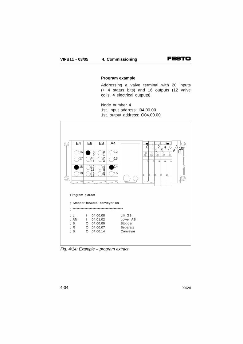
Program example
Addressing a valve terminal with 20 inputs(+ 4 status bits) and 16 outputs (12 valvecoils, 4 electrical outputs).
Node number 41st. input address: I04.00.001st. output address: O04.00.00
E4 E8 A4E8
8
10
12
14
9
11
13
15
16
17
18
19
0
2
4
6
1
3
5
7
12
13
14
15
23
45
67
0 1 89 10
11
Program extract
; Stopper forward, conveyor on
; **************************************
; L I 04.00.08 Lift GS; AN I 04.01.02 Lower AS; S O 04.00.00 Stopper; R O 04.00.07 Separate; S O 04.00.14 Conveyor
Fig. 4/14: Example – program extract
VIFB11 - 03/05 4. Commissioning
4-34 9902d

Diagnosis
The following SELECAN bus diagnoses areavailable in the PMC 40:
• diagnosis via the PMC 40
• diagnosis via the user program
Diagnosis via the PMC 40
The FESTO valve terminals behave on theSELECAN in respect of diagnosis like equival-ent Selectron CAN-I/O modules. Special errormessages are not shown.
Diagnosis via the user program
With the user program you can interrogate thediagnostic information of a bus slave by meansof the following operands:
• system flags
• status bits of the valve terminals
System flags SM11.01 - SM11.29
With the system flags SM11.01 - SM11.29, youcan interrogate whether the relevant SELECANbus slave (valve terminal) is active or inactiveat the moment. There is a system flag for eachnode number (=station number).
SM11.01 for node number 1SM11.02 for node number 2, etc..
VIFB11 - 03/05 4. Commissioning
9902d 4-35
System flags SM12.01 - SM12.29
With the system flags SM12.01 - SM12.29, youcan interrogate in conjunction with the FESTOvalve terminal whether at least one electricaloutput of the valve terminal is overloaded orshort-circuited. There is a system flag for eachnode number (station number).
SM12.01 for short circuit/overload node 1SM12.02 for short circuit/overload node 2etc.
For eliminating the error, please consult Chap-ter 5, Diagnosis/error treatment, Section 5.4,Eliminating errors.
Status bits
The status bits signalize internal errors to thevalve terminal. The following errors are recog-nized:
• undervoltage valves/outputs< 21.6 V
• undervoltage valves/outputs< 10 V
• short circuit/overload of at least one electri-cal output
• undervoltage sensor supply< 10 V
Further details can be found in Chapter 5"Diagnosis and error treatment" (Chapter 5.4Status bits).
VIFB11 - 03/05 4. Commissioning
4-36 9902d

The status bits are treated and transferred likeinputs. They always occupy the four highest-value addresses of the available addressrange. If the inputs of the input addressesthereunder are not used, the valve terminal willset them to "logic zero".
The table below shows the addresses of thestatus bits in the address range of a valveterminal, depending on the equipment fitted onthe terminal.
Number ofinput bytes
Availableaddress range
Addressesof the status bits
None No address range for inputs No status bits available
1 input byte 0 ... 7 4, 5, 6, 7
2 input byte 0 ... 15 12 ... 15
3 input byte 0 ... 23 20 ... 23
4 input byte 0 ... 31 28 ... 31
5 input byte 0 ... 39 36 ... 39
6 input byte 0 ... 47 44 ... 47
7 input byte 0 ... 55 52 ... 55
8 input byte 0 ... 63 60 ... 63
VIFB11 - 03/05 4. Commissioning
9902d 4-37
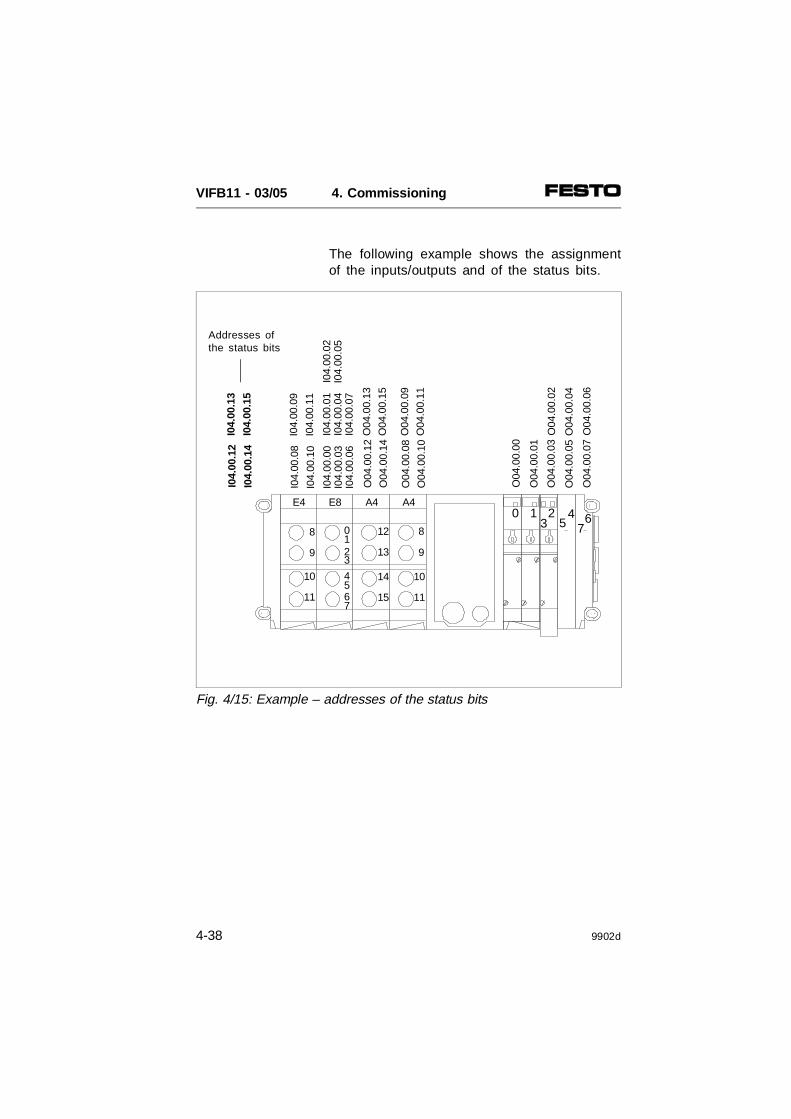
The following example shows the assignmentof the inputs/outputs and of the status bits.
A4A4E8E4O
04.0
0.00
O04
.00.
01
O04
.00.
03
O04
.00.
05
O04
.00.
07
I04.
00.0
0I0
4.00
.01
I04.
00.0
3I0
4.00
.04
I04.
00.0
2I0
4.00
.05
I04.
00.0
6I0
4.00
.07
I04.
00.0
8I0
4.00
.09
I04.
00.1
0I0
4.00
.11
O04
.00.
08O
04.0
0.09
O04
.00.
10O
04.0
0.11
O04
.00.
12O
04.0
0.13
O04
.00.
14O
04.0
0.15
0
2
4
6
1
3
5
7
12
13
14
15
8
9
10
11
8
9
10
11
I04.
00.1
2I0
4.00
.13
I04.
00.1
4I0
4.00
.15
O04
.00.
02
O04
.00.
04
O04
.00.
06
23
45 6
70 1
Addresses ofthe status bits
Fig. 4/15: Example – addresses of the status bits
VIFB11 - 03/05 4. Commissioning
4-38 9902d

4.2.3 Allen-Bradley DeviceNet
PLEASE NOTE– The Festo valve terminal with FB11 can be
used on all DeviceNet masters.– This chapter deals with the configuration
and commissioning using as an example the controllers from Allen-Bradley.
General
If the modular valve terminal is used with theAllen-Bradley DeviceNet, the following pointsmust be observed:
• The addresses of all network modules,including the valve terminals, can be freelyassigned to the M files or as discrete I/Osto the I/O files in the scan list table.
• The input and output addresses can beassigned independently of each other.
PLEASE NOTEAssign the addresses of the network modulesso that there is enough reserve for later exten-sions to the inputs and outputs of the valveterminal.
VIFB11 - 03/05 4. Commissioning
9809c 4-39

The following sections describe the addressassignment and all the necessary configurationspecifications for the valve terminal with thesoftware package "DeviceNet Manager" (3.005).
PLEASE NOTEThe software packages are subject to modifi-cations which are not taken into considerationin this manual. The examples of the screen displays here aretaken from the English version DN-MGR-ver-sion 3.005. Further more up-to-date information can befound in the manual for the DeviceNet Man-ager or in the online help.
VIFB11 - 03/05 4. Commissioning
4-40 9809c

Festo SF 60 as DeviceNet master
A DeviceNet master from Festo is available inthe form of the SF 60 programmable valveterminal (SLC embedded). The controller incor-porated in the SF 60 corresponds to anSLC5/02 with DeviceNet scanner 1747-SDNfrom Allen-Bradley.
PLEASE NOTEAll steps listed for the Allen-Bradley 1747-SDNscanner also apply to the SF 60 as master.For reasons of clarity, a distinction betweenthese two devices is not therefore made in thefollowing text.
CD ROM "Utilities"
For the Festo valve terminals you will findproduct-specific icons/bitmaps and some EDSfiles for DeviceNet on the accompanying CDROM.
• Read the file "Readme.txt" on the CD ROM,where applicable, for a brief summary of thecontents of the CD ROM.
PLEASE NOTEThe EDS files for the FB11-03 are availableas from CD-ROM version 9904b and are suit-able only for field bus nodes as from softwareversion V2.0 (26.02.99) or higher.
VIFB11 - 03/05 4. Commissioning
9809c 4-41

Extending the EDS library
When you commission a valve terminal withthe DeviceNet Manager for the first time, youmust first extend the EDS library of theDeviceNet Manager. For this purpose, Festooffers two EDS files and suitable bit-maps/icons. Please note that you must adaptthe number of required I/O bytes for eachvalve terminal later in the project under EditI/O Parameters.
PLEASE NOTE– The valve terminal only supports the trans-
mission mode Polled Connection.– As from February 1999, field bus nodes of
type FB11 will be delivered with an updatedand improved software version for the DeviceNet. This new software version offerssimpler configuration and commissioning of a valve terminal on the DeviceNet. CompleteEDS files (new product code, major/minor revision 2.0) are available for this new soft-ware on the accompanying CD-ROM.
– The new software version is no longer com-patible with earlier field bus nodes (softwarestatus 22.07.96 or earlier, major/minor revi-sion V1.3/1.4). However, you can switch over to the old software version with DILswitch 4 and thereby create compatibility with an older DeviceNet configuration (seeChapter 3.2, "Setting the compatibility”). Youmust enter the EDS files for these earlier software versions of the valve terminal in the DeviceNet Manager individually and manually.
VIFB11 - 03/05 4. Commissioning
4-42 9809c

The following possibilities are available forextending the EDS library:
– installing the EDS file (recommended variant)
– reading out EDS information in online mode(see manual for the DeviceNet Manager)
– entering the slaves manually (see manual forthe DeviceNet Manager and Appendix B.5 inthis manual).
Installing the EDS file (recommended variant)
For extending the EDS library, a CD-ROM isprovided with this manual. This CD-ROMcontains suggestions for two EDS files as wellas icons/bitmaps for valve terminals types03/05. In order to install an EDS file, proceedas follows:
1. Activate the command Install EDS Files in themenu Utilities.
2. Place the CD-ROM (part number 384676,version 9904b or later) in your CD-ROMdrive and switch to the appropriate drive. Select the sub-directory "DeviceNet".The file Readme.txt in the main directory ofthe CD-ROM contains information on the directory structure of the CD-ROM.
VIFB11 - 03/05 4. Commissioning
9809c 4-43

3. Select file DNF11io.eds for valve terminalstypes 03/05 with I/O modules or fileDNF11vv.EDS for a valve terminal withoutI/O modules.
4. Confirm selection with OK. The message"Set Device Bitmap?" will then appear.
5. Confirm with YES and select fileDNF11io.bmp or DNF11vv.BMP (*.bmp) appropriate to the EDS file. Save the values with OK.
The valve terminal is now entered in the slavelist of the DeviceNet Manager as a new,possible DeveiceNet slave. It can now beadded to a network or project.
Extending the network with a valve terminal
When a project is opened or created, you canadd a valve terminal online or offline.
A valve terminal can be added online as follows:
• Provide an online connection between yourPC and the DeviceNet.
• Activate the function Start Online Build inthe menu Utilities. A list of all the networkmodules connected to the DeviceNet willthen appear.
VIFB11 - 03/05 4. Commissioning
4-44 9809c

A valve terminal can be added offline as follows:
1. Double click "Valve terminal/manifold" andthen "Festo" in the device list in order to openthe list of available valve terminals.
2. Click the entry "IFB11-03" and more the sym-bol to the right into the project window.
Fig. 4/16: Project view in offline configuration
VIFB11 - 03/05 4. Commissioning
9809c 4-45

3. Now enter the set station number and, ifnecessary, a brief description of the valveterminal in the field Node Address.
PLEASE NOTEThe entries "Festo" and "IFB11..." are onlydisplayed if the EDS library has been extended as described.
4. The valve terminal will then be added to thecurrent network. A summary of all configurednetwork modules will then appear.
Fig. 4/17: Summary of the configured network modules (example)
VIFB11 - 03/05 4. Commissioning
4-46 9809c
Every network module in the project windowcan usually be configured. For the completeconfiguration of a valve terminal, only thenumber of inputs and outputs and their positionin the PLC address range need to be entered.With the aid of the function Node Commission-ing in the menu Utilities, you can usuallyassign a new station number (node address)and new baud rate (data rate) to a networkmodule.
PLEASE NOTEThese settings can only be made on the valveterminal by means of the integrated switches(see chapter 3).
Configuring the scanner
Calculate first the number of input/output bytesof the individual valve terminals as describedbelow or read these values out of the terminal(double click on the icon of the terminal, asfrom node V2.0).
PLEASE NOTEIf input modules are fitted, the number of inputbits per valve terminal will be increased by 4status bits.
You can now configure the scanner by settingthe number of I/Os, their position in the PLCaddress range and the transmission mode.
VIFB11 - 03/05 4. Commissioning
9809c 4-47

Entering the number of I/Os
PLEASE NOTEIn order to maintain faultless configuration, youmust enter the exact number of I/Os for eachvalve terminal in the project as describedbelow.
1. Double click in the project window the scan-ner used. The dialogue box 17...-SDN Moduleand Channel Configuration will then open.
2. Activate the field Edit Scan List. The followingdialogue box will then appear.
Fig.4/18: Dialogue box "Scan List Editor", example 1771-SDN
VIFB11 - 03/05 4. Commissioning
4-48 9809c

3. Select the valve terminal to be configured andactivate the field Edit I/O Parameters. The fol-lowing dialogue box will then appear.
4. Activate the entry Enable in the group Polled.
Input bytes Output bytes
Fig.4/19: Dialogue box "Edit Device I/O Parameters", example with 2 input and 6 output bytes
VIFB11 - 03/05 4. Commissioning
9809c 4-49

5. Enter the number of input/output bytes of thevalve terminal in the field Polled Size (inbytes. The values ascertained in Chapter 4.1may have to be rounded up).
PLEASE NOTEIf the valve terminal is extended/convertedat a later stage, these values may have tobe adjusted.
Tip:As from field bus node V2.0 you can alsoread out these values online from the valveterminal (by double-clicking the icon of thevalve terminal in the project window).
6. Select the entry Every Scan in the field PollRate. Then confirm the entry with OK. Thedialogue box will then be closed.
VIFB11 - 03/05 4. Commissioning
4-50 9809c

Assignment and transmission mode
The inputs and outputs of the valve terminalcan be assigned to PLC operands with thefunctions Auto Map or Datatable Map.
Proceed as follows for the assignment with thefunction Datatable Map:
1. Activate the function Datatable Map. Thefollowing dialogue box will then appear.
2. The DeviceNet configurator enables you toform up to 4 different address list segmentsfor data exchange. Select the desired seg-ment number in the field Map Segment.
Fig.4/20: Example dialogue box "1771-SDN Datable Map"
VIFB11 - 03/05 4. Commissioning
9809c 4-51

3. Select the communication type Poll Messagefor both inputs and outputs.
PLEASE NOTEThe valve terminal only supports thecommunication type Poll Message, bothfor inputs and outputs.
With the following settings you can determine:
• As from which input/output of the valveterminal data are to be transferred.
• To/from where the data are to be trans-ferred (data files or discrete I/Os).
• How many input/output bits of a valveterminal are to be transferred. Normally, allthe input/output bits of a valve terminal aretransferred.
4. Select the entry Input in the field Data Mapand enter the desired starting address of theinputs of the valve terminal in the fields Byteand Bit.
Transmission mode
Address list segments
Fig. 4/21: Address list segments and trans- mission mode
VIFB11 - 03/05 4. Commissioning
4-52 9809c
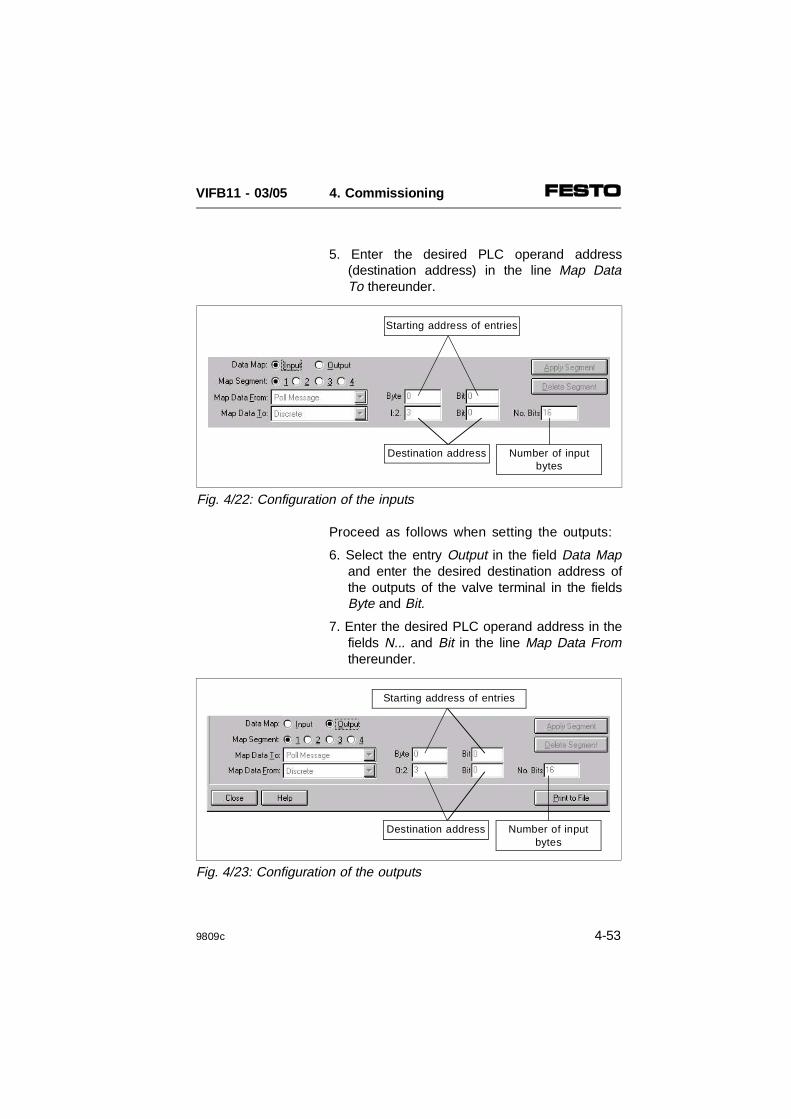
5. Enter the desired PLC operand address(destination address) in the line Map DataTo thereunder.
Proceed as follows when setting the outputs:
6. Select the entry Output in the field Data Mapand enter the desired destination address ofthe outputs of the valve terminal in the fieldsByte and Bit.
7. Enter the desired PLC operand address in thefields N... and Bit in the line Map Data Fromthereunder.
Destination address
Starting address of entries
Number of inputbytes
Fig. 4/23: Configuration of the outputs
Destination address
Starting address of entries
Number of inputbytes
Fig. 4/22: Configuration of the inputs
VIFB11 - 03/05 4. Commissioning
9809c 4-53
Configuring a further map segment will enableyou to transfer, for example, the 4 status bitsof the valve terminals. These can then begrouped together as a diagnostic file. In thisway, evaluation of the status bits is consider-ably simplified.
The settings in the list fields Map Data To(inputs) and Map Data From (outputs) dependon the scanner used. Possible settings forscanners 1771-SDN and 1747-SDN are ex-plained in subsequent sections.
VIFB11 - 03/05 4. Commissioning
4-54 9809c

Scanner 1771-SDN (PLC 5 series)
With scanner 1771-SDN, you can assign theinputs and outputs of the valve terminal bymeans of:
• block transfer (BT 62 to BT 57)
• discrete inputs/outputs.
The maximum number of addressable discreteinputs/outputs depends on the slot setting ofthe rack:
• 1⁄2 slot = 24
• 1 slot = 8
• 2 slot = 0 discrete I/Os.
Fig. 4/24: Selection "Map Data To"
VIFB11 - 03/05 4. Commissioning
9809c 4-55

Scanner 1747-SDN (SF 60 and SLC 500 series)
With scanner 1747-SDN, you can assign theinputs and outputs by means of:
• discrete inputs/outputs
• SLC M0/M1 file
The maximum number of discrete inputs/out-puts can amount to 496 I/Os.
Fig. 4/25: Selection "Map Data To"
VIFB11 - 03/05 4. Commissioning
4-56 9809c

Example 1: Scanner 1771-SDN (PLC 5 series)
Valve terminal #4 with:
• 4 input bytes, file N9, from word 2, bit 0
• 2 output bytes, file N10, from word 2, bit 0
In this example all 32 inputs and all 16 outputsare to be transferred.
Fig. 4/26: Configuration example for scanner 1771-SDN
N10
.02:
00N
10:0
2.01
N10
:02:
02N
10:0
2.04
N10
:02.
06N
10:0
2.08
N10
:02.
10
N10
:02.
15 -
N10
:02.
12
N9:
02.0
7 -
N9:
02.0
0
N9:
02.1
5 -
N9:
02.0
8
N9:
03.0
7 -
N9:
03.0
0
N9:
03.1
1 -
N9:
03.0
8
N10
:02.
03N
10:0
2.05
N10
:02.
07N
10:0
2.09
N10
:02.
11
* ****
#4
0 1 23
45
67 11
10*8
9
A4E4 E8 E8 E8
12
13
14
15
10
32
54
76
98
1110
1312
1514
1716
1918
2120
2322
24
25
26
27
* = not used, ** = free due to rounding
**
Fig. 4/27: Addressing example for scanner 1771-SDN
VIFB11 - 03/05 4. Commissioning
9809c 4-57

] [ )(N9:2
8
N10:2
1
] [ )(N9:2
8
N10:2
7
] [ )(N9:3
2
N10:2
14
A4E8
8
10
12
14
9
11
13
15
E8E4
24
25
26
27
E8
0
2
4
6
1
3
5
7
12
13
14
15
16
18
20
22
17
19
21
23
23
45
67
0 1 89 10
11*
Program extract
; Stopper forward, conveyor on
Fig. 4/28: Example – programm extract (scanner 1771 SDN)
VIFB11 - 03/05 4. Commissioning
4-58 9809c

Example 2: Scanner 1747-SDN(SLC 500 series)
Valve terminal #12 with:4 input bytes, input address from I:004/002 output bytes, output address from O:004/00
In this example all 32 inputs and all 16 outputsare to be transferred.
Fig. 4/29: Configuration example for scanner 1747-SDN
O:0
04.0
0O
:004
.01
O:0
04.0
2O
:004
.04
O:0
04.0
6O
:004
.08
O:0
04.1
0
O:0
04.1
5 -
O:0
04.1
2
I:004
.07
- I:0
04.0
0
I:004
.15
- I:0
04.0
8
I:005
.07
- I:0
05.0
0
I:005
.11
- I:0
05.0
8
#12
0 1 23
45
67 11
10*8
9
O:0
04.0
3O
:004
.05
O:0
04.0
7O
.004
.09
O:0
04.1
1
* ****
A4E4 E8 E8 E8
12
13
14
15
10
32
54
76
98
1110
1312
1514
1716
1918
2120
2322
24
25
26
27
* = not used, ** = free due to rounding
**
Fig. 4/30: Addressing example for scanner 1747-SDN
VIFB11 - 03/05 4. Commissioning
9809c 4-59

] [ )(I:004
12
O:004
05
] [ )(I:005
11
O:004
13
] [ )(I:004
02
O:004
00
0 1 23
45
67 11
10*8
9
A4E4 E8 E8 E8
12
13
14
15
10
32
54
76
98
1110
1312
1514
1716
1918
2120
2322
24
25
26
27
Program extract
; Stopper forward, conveyor on
Fig. 4/31: Example - programm extract (scanner 1747 SDN)
VIFB11 - 03/05 4. Commissioning
4-60 9809c

Explicit message
DeviceNet scanner 1771-SDN/B provides theExplicit Message Program Control Feature.With this function typical data of the valveterminal, as, for example, output via thefunction Network Who, can be read into theuser program and processed there.
This data can be read and written by means ofBTR 62 or BTW 62. Please refer to yourscanner manual for details of this function.
The following data can be read from the valveterminal:
Objectclass
Class ID Instance Attribute Function Value
Identity 1 1 1 Vendor ID 26D 1AH
2 Product type 25D 19H
3 Product code 35050D 88EAH 1)
2282D 08EAH 1)
4 Revision V2.0
5 Status 0
6 Series number Field bus nodespecific
7 Name IFB11-03/51) As from software status V2.0 (26.02.99)
VIFB11 - 03/05 4. Commissioning
9809c 4-61

Diagnosis
The following bus diagnoses are available:
• Diagnosis via DeviceNet scanner
• Diagnosis via user program
Diagnosis via DeviceNet scanner
The valve terminal reacts on the DeviceNet inrespect of the diagnosis like the equivalentDeviceNet modules. There are no special errormessages.
Diagnosis via user program
The following diagnostic possibilities are avail-able via the user program:
• Evaluation of the device failure table
• Evaluation of the status bits
Device failure table
The device failure table is divided into severalsections. The section Communications FailureBitmap is interesting in conjunction with thevalve terminal. In this section an error bit is setfor every DeviceNet slave, if communicationbetween the scanner and the slave is inter-rupted or faulty.
The error bit is set in the valve terminal whenit is not supplied with voltage, when the busconnection is interrupted (e.g. plug removed)or when the bus interface is not supplied withvoltage.
VIFB11 - 03/05 4. Commissioning
4-62 9809c

Status bits
The status bits signalize internal faults in thevalve terminal. The following faults are recog-nized:
• Undervoltage at valves/outputs < 21.6 V
• Undervoltage at valves/outputs < 10 V
• Short circuit/overload of at least one elec-trical output
• Undervoltage in sensor supply < 10 V
Further details can be found in chapter 5"Diagnosis and error treatment" (chapter 5.4Status bits).
VIFB11 - 03/05 4. Commissioning
9809c 4-63

VIFB11 - 03/05 4. Commissioning
4-64 9809c

5. DIAGNOSIS AND ERROR TREATMENT
VIFB11 - 03/05 5. Diagnosis and error treatment
9902d 5-1

Inhalt
5.1 ÜBERSICHT DIAGNOSE-MÖGLICHKEITEN 5-3
5.2 DIAGNOSE VOR ORT 5-4LED-Anzeigen (Knoten) 5-4Ventile 5-7Ein-/Ausgangsstufen 5-9Test der Ventile 5-10
5.3 STATUSBITS 5-12
5.4 FEHLERBEHANDLUNG 5-15Verhalten bei Störungenim Steuerungssystem 5-15Kurzschluß/Überlast an einer Ausgangsstufe 5-16
VIFB11 - 03/05 5. Diagnosis and error treatment
5-2 9902d

5.1 SUMMARY OF DIAGNOSTIC POSSIBILITIES
The modular valve terminal offers comprehen-sive and user-friendly possibilities for diagnosisand error treatment. The following possibilitiesare available depending on the equipmentfitted on the terminal.
Equipment fitted on the valve terminal
Input modules(electrical inputs)
FB11
Diagnosticpossibilities
Status bits
X = not relevant
LEDs
Briefdescription
The four status bits aretransferred cyclically to thefield bus module as "inputs"together with the normalinputs.
The LEDs show directlyconfiguration errors, hardwareerrors and bus errors.
Advantage Fast access to error messages Fast "on-the-spot" error recognition
Detailed description
Chapter 5.3 Chapter 5.2
Fig. 5/1: Possibilities of diagnosis and error treatment
AAAAAA
POWER
AAAAERRORAAAA
MOD/NET
AAAABUS
BUS
POWER
STATUS
Status bits Meaning
Bit 7
Bit 6
Bit 5
Bit 4
0XXX1
0011X
0101X
0XXXX
No errorS.C./OVval < 21.6VVout < 10 VVsen < 10 V
VIFB11 - 03/05 5. Diagnosis and error treatment
9902d 5-3

5.2 ON-THE-SPOT DIAGNOSIS
LED display (node)
The LEDs on the cover of the node supplyinformation on the operating status of the valveterminal.
The following tables show the various oper-ating states indicated by the LEDs.
LED Meaning
LED is out
LED lights up
LED flashes
AAAAAAAAAAAAPOWER
AAAAAAAAAAAA
ERROR
AAAAAAAAA
AAAAAAAAAAAAAAAA
BUS
MOD/NETSTATUS
BUSPOWER
Green LED(display for node OK)
Green LED (display forvoltagesupply)
Red LED(error display)
Green LED(display for bus voltagesupply)
Fig. 5/2: LEDs on the node
VIFB11 - 03/05 5. Diagnosis and error treatment
5-4 9902d

Reaction Sequence Operating status Error treatment
POWER LED
Operating voltage applied None
Operating voltage notapplied
Check operating voltageconnection for electroniccomponents (pin 1).
BUS POWER LED
Operating voltage of businterface applied
None
Operating voltage of businterface not applied
Check bus operating voltage connection(bus plugs pins 2 and 3)
MOD/NET STATUS LED
Operating status normaloroperating status normal,but valves do not switch.Possible causes:• compressed air supply
not correct • pilot exhaust blocked
None
Check the ...
• compressed air supply
• pilot exhaust channels
• Flashes once whenswitched on (LED test)
• Valve terminal is readyfor data exchange, butis not yet initialized bythe master after beingswitched on
• None
• Start communication
Only with Selectron/Philips• Valve terminal in
stand-by mode
Start communication
Fig. 5/3a: LED display of operating status
ON
OFF
ON
OFF
ON
OFF
ON
OFF
ON
OFF
ON
OFF
ON
OFF
VIFB11 - 03/05 5. Diagnosis and error treatment
9902d 5-5

Reaction Sequence Operating status Error treatment
ERROR LED
No internal terminal error,No fitting error
None
• Non-permitted station number set, stationaddress assigned twiceor max. value exceeded
• Too many transmission errors (error counteroverrun)
• Correct stationaddress
• Check cables/plugconnectors, switch valveterminal on again
• Flashes once when switched on (LED test)
• Time-out expired, novalid telegrams received during the time-out time, bus error, communication error or loss ofcommunication
• Error in valve test
• None
• Check connection toPLC
• Start valve test again
Modules not fittedcorrectly:• more than 12 I/O
modules fitted• max. permitted number
of inputs exceeded • max. permitted number
of outputs exceeded
Reduce the ...
• number of I/O modules
• number of inputmodules
• number of outputmodules
Hardware error Servicing required
Fig. 5/3b: LED display of operating status (continued)
ON
OFF
ON
OFF
ON
OFF
ON
OFF
ON
OFF
VIFB11 - 03/05 5. Diagnosis and error treatment
5-6 9902d
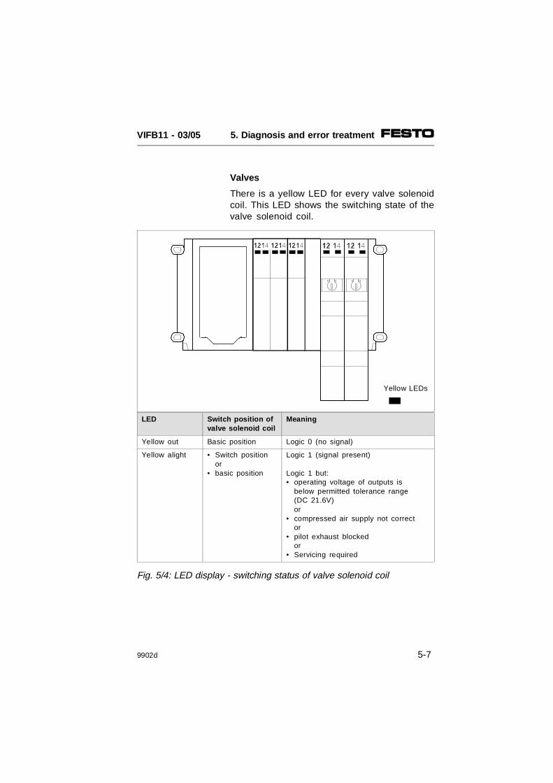
Valves
There is a yellow LED for every valve solenoidcoil. This LED shows the switching state of thevalve solenoid coil.
Yellow LEDs
LED Switch position ofvalve solenoid coil
Meaning
Yellow out Basic position Logic 0 (no signal)
Yellow alight • Switch positionor
• basic position
Logic 1 (signal present)
Logic 1 but:• operating voltage of outputs is
below permitted tolerance range (DC 21.6V) or
• compressed air supply not corrector
• pilot exhaust blockedor
• Servicing required
Fig. 5/4: LED display - switching status of valve solenoid coil
VIFB11 - 03/05 5. Diagnosis and error treatment
9902d 5-7
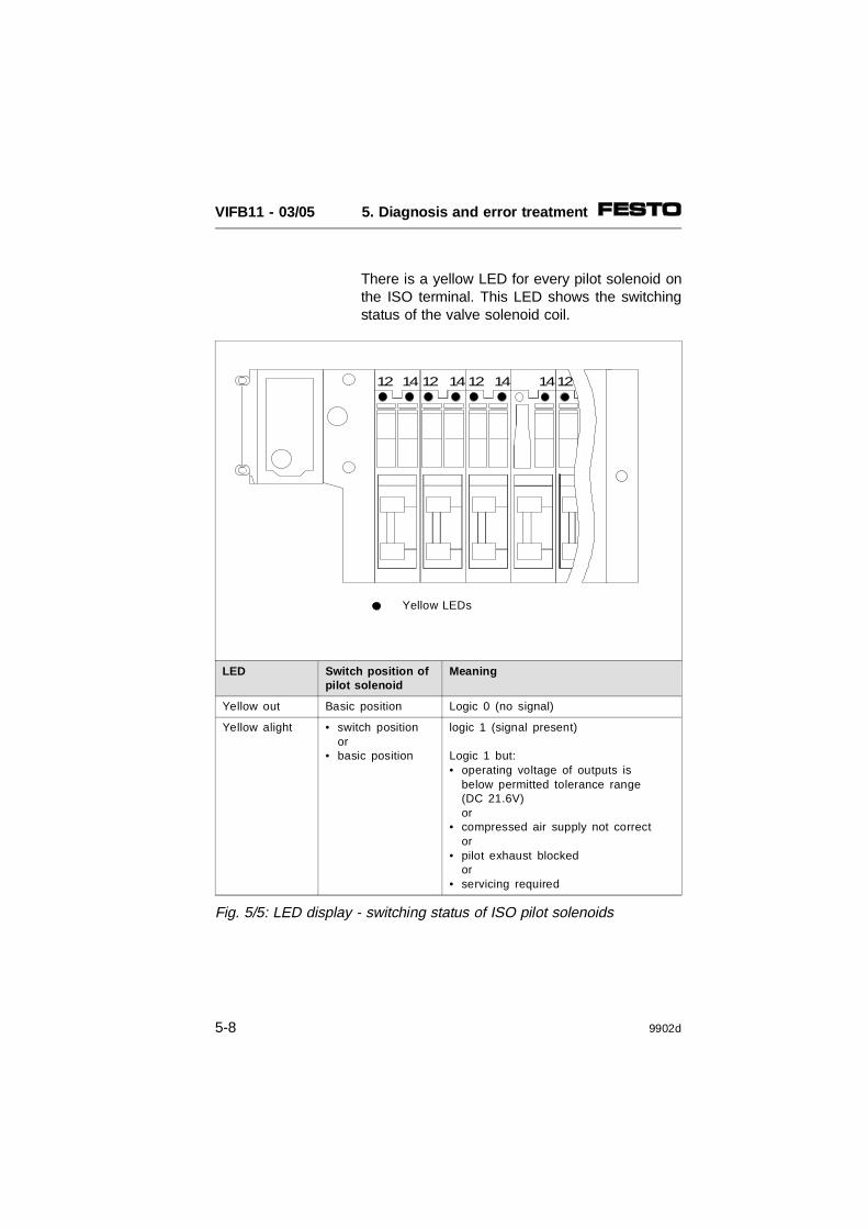
There is a yellow LED for every pilot solenoid onthe ISO terminal. This LED shows the switchingstatus of the valve solenoid coil.
12 14 12 1412 14 1214
Yellow LEDs
LED Switch position ofpilot solenoid
Meaning
Yellow out Basic position Logic 0 (no signal)
Yellow alight • switch positionor
• basic position
logic 1 (signal present)
Logic 1 but:• operating voltage of outputs is
below permitted tolerance range (DC 21.6V) or
• compressed air supply not corrector
• pilot exhaust blockedor
• servicing required
Fig. 5/5: LED display - switching status of ISO pilot solenoids
VIFB11 - 03/05 5. Diagnosis and error treatment
5-8 9902d

Input/output modules
In addition to the relevant connections, thereare one or two LEDs (status displays) on theinput/output modules. These LEDs have thecolours:• green (status display of the digital inputs).• yellow (status display of the digital outputs)• red (error display of the digital outputs)
The current signal at the relevant input oroutput is shown by means of the yellow andgreen LEDs. The red LEDs of the outputsindicate a short ciruit or overload at theappropriate output.
Red LEDs (shortcircuit/overload display ofoutputs)
Yellow LEDs(Switching statusdisplay of outputs)
Green LEDs(Switching statusdisplay of inputs)
I8 I8 I4 O4
LED Status
Yellow outorgreen out
Logic 0(no signal)
Yellow alightorgreen alight
Logic 1(signal present)
Red out Output without short circuit/overload
Red alight Short circuit/overload at relevant output
Fig. 5/6: LED displays of input/output modules
VIFB11 - 03/05 5. Diagnosis and error treatment
9902d 5-9

Testing the valves
WARNING Before starting the test, switch off the com-pressed air supply to the valves.
In this way you can avoid undesired ordangerous movements of the actuators.
CAUTION• This test function runs automatically within
the terminal. All the valves are switched on and off cyclically.
• None of the programmed lockings or furtherswitching conditions will be taken into account.
The terminal makes the following test routinesavailable with which all the valves are switchedon and off cyclically:
Testroutine Meaning
Parallel All outputs are switched on and offsimultaneously at 1 s intervals.
Serial All outputs are switched on and off oneafter the other at 1 s intervals.
Fig. 5/7: Test routines
VIFB11 - 03/05 5. Diagnosis and error treatment
5-10 9902d

Starting the test routine
1. Switch off the operating voltage supplies (pins1 and 2).
2. Open the node.
3. Note the position of the address selectorswitch and of the DIL switch elements.
4. Set address 99 and set DIL switch elements1 and 2 to OFF, and 3 and 4 to ON.
5. Switch on the operating voltage supplies (pins1 and 2).
6. Set the desired test routine on the addressselector switches as follows:
7. Start: set DIL switch elements 1 and 2 to ON.
If errors occur when the test routine is started,the red LED on the node will flash quickly. Theprocedure must then be repeated.
Stopping the test routine
1. Switch off the operating voltage supply to theterminal (pins 1 and 2).
2. Reset the address selector switch and DILswitch elements to their original positions.
Test routine Address to be set
Parallel 0, 1 or 2
Serial 3
Fig 5/8: Setting the test routines
VIFB11 - 03/05 5. Diagnosis and error treatment
9902d 5-11

5.3 STATUS BITS
The modular valve terminal makes available 4status bits for diagnostic purposes, irrespectiveof the protocol set.
PLEASE NOTEThe four status bits of the valve terminal areonly available when the terminal is fitted withinput modules.
The status bits are configured like inputs andalways occupy the four highest-value ad-dresses in the available address range.
The position of the 4 status bits within theaddress range of the valve terminal is ex-plained in the following chapters:
• 4.2.1 for Philips DIOS
• 4.2.2 for Selectron SELECAN
• 4.2.3 for Allen-Bradley and Festo DeviceNet
The status bits are made available at theseaddresses as soon as there are inputs. If theinputs of the addresses thereunder are notused, the terminal will set them at "logic zero".
VIFB11 - 03/05 5. Diagnosis and error treatment
5-12 9902d

The four status bits supply coded diagnosticinformation with the following meaning:
Status bits*) Diagnostic information
27 26 25 24
0 0 0 0 No error
X 0 1 X Short circuit overload at output
X 1 0 X Vvalves < 21.6 V
X 1 1 X Voutputs < 10 V
1 X X X Vsensor < 10 V
X = not relevant*) The status bits can always be addresed by the four highest-value addresses of the configured address range
Fig. 5/9: Coded diagnostic information of the four status bits
VIFB11 - 03/05 5. Diagnosis and error treatment
9902d 5-13

Diagnosticinformation
Description Function
Shortcircuit/overloadat output
Output short-circuited oroverloaded
Monitors the electricaloutputs of the outputmodules.
Vvalves < 21.6 V Operating voltage at pin 2(valves and outputs) of theoperating voltage connection< 21.6 V
Monitors the tolerance ofthe operating voltage forvalves and electricaloutputs.
Voutputs < 10 V Operating voltage at pin 2(valves and outputs) of theoperating voltage connection< 10 V
Monitors the operatingvoltage for valves andelectrical outputs (novoltage, e.g. EMERGENCYSTOP).
Vsensor < 10 V Operating voltage at pin 1(electronic components andinputs) of the operatingvoltage connection < 10 V
Monitors the supply voltagefor inputs (sensors).Indicates whether aninternal fuse has beentriggered (fuse on node orat least an electronic fuseon input module 1) VIGE-03-FB-8-5).
1) Electronic fuse for input modules only available as from V2.0 (26.02.99)
Fig. 5/10: Diagnostic information
VIFB11 - 03/05 5. Diagnosis and error treatment
5-14 9902d

5.4 ERROR TREATMENT
Reaction to faults in the control system
PLEASE NOTEIf all outputs are reset after a PLC stop or ifthere is an interruption or fault in the fieldbus, the following "pneumatic rules" must beobserved:• unilaterally actuated valves assume the
basic position • double solenoid valves remain in their
current position• mid-position valves assume the mid-
position and (depending on valve type)are pressurized, exhausted or blocked.
PLC/Protocol
Reaction of terminal
- to PLC stop - to field busfaults
- to field businterruptions
Allen-Bradley DeviceNet
Valve andelectrical outputsare reset .
Valves andelectrical outputsare reset whentime-out hasexpired
Valves andelectrical outputsare resetimmediately.
PhilipsDIOS
Valve andelectrical outputsare not reset .
SelectronSELECAN
Valve andelectrical outputsare reset .
Fig. 5/11: Reaction of the valve terminal to faults
VIFB11 - 03/05 5. Diagnosis and error treatment
9902d 5-15

Short circuit/overload at an output module
If there is a short circuit or overload:
• the digital output will be switched off,
• the red LED will light up,
• the error code "short circuit overload" willbe entered in the four status bits.
In order to reactivate the output, proceed asfollows:
The output can then be reset to "logic 1".If the short circuit still exists, the output will beswitched off again.
Step Explanation
Eliminate short circuit or overload
Set output at 0 (RESET) • Manual in on-line mode• Automatic in PLC program
Fig. 5/12: Eliminating short circuit/overload
VIFB11 - 03/05 5. Diagnosis and error treatment
5-16 9902d

APPENDIX A
DEVICENET SPECIFICATIONS
VIFB11 - 03/05 A. DeviceNet Specifications
9902d A-1

Contents
A.1 OVERVIEW DEVICENET-SPECIFICATIONS A-3General DeviceNet Information A-3DeviceNet - Message Types A-4DeviceNet - Class and Instance Services A-4DeviceNet - Object Classes A-4
A.2 DETAILS ON DEVICENET OBJECTS A-5
A.2.1 Identity Object: Class Code 01 (0x01) A-5Identity Object Class Attributes A-5Identity Object Instance 1 Attributes A-5Common Services A-6
A.2.2 Router Object: Class Code 02 (0x02) A-7Router Object Class Attributes A-7Router Object Instance 1 Attributes A-7Common Services A-7
A.2.3 DeviceNet Object: Class Code 03 (0x03) A-8DeviceNet Object Class Attributes A-8Router Object Instance 1 Attributes A-8Common Services A-8
A.2.4 Assembly Object: Class Code 04 (0x04) A-10Assembly Object Instance 1 Attribute 3 A-11Instance 2 Attribute 3 A-12Common Services A-13
A.2.5 Connection Object: Class Code 05 (0x05) A-13Connection Object Class Attributes A-13Connection Object Instance 1 Attributes (Explicit Message) A-14Connection Object Instance 2 Attributes (POLL connection) A-15Common Services A-16
VIFB11 - 03/05 A. DeviceNet Specifications
A-2 9902d

A.1 OVERVIEW DEVICENET-SPECIFICATIONS
PLEASE NOTE:– The following pages contain the DeviceNet
specifications of the Festo field bus nodesIFB11-02 and IFB11-03.
– These nodes are used for the Festo valveterminals (manifolds) types 02, 03, 04-B and 05.
– Their current DeviceNet Specifications Release is 1.3
General DeviceNet Information
The IFB11-02/03 (Festo valve terminal) deviceoperates as a slave on the DeviceNet network.As a DeviceNet slave, the valve terminalsupports the following in the assigned mas-ter/slave connection:
– Explicit Messages
– Polled I/O Messages.
It does not support the Explicit UnconnectedMessage Manager (UCMM).
VIFB11 - 03/05 A. DeviceNet Specifications
9902d A-3
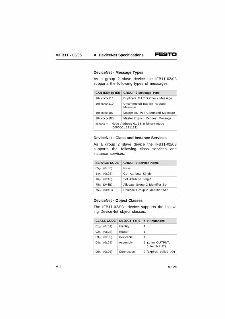
DeviceNet - Message Types
As a group 2 slave device the IFB11-02/03supports the following types of messages:
CAN IDENTIFIER GROUP 2 Message Type
10xxxxxx111 Duplicate MACID Check Message
10xxxxxx110 Unconnected Explicit Request Message
10xxxxxx101 Master I/O Poll Command Message
10xxxxxx100 Master Explicit Request Message
xxxxxx = Node Address 0...63 in binary mode(000000...111111)
DeviceNet - Class and Instance Services
As a group 2 slave device the IFB11-02/03supports the following class services andinstance services:
SERVICE CODE GROUP 2 Service Name
05D (0x05) Reset
14D (0x0E) Get Attribute Single
16D (0x10) Set Attribute Single
75D (0x4B) Allocate Group 2 Identifier Set
76D (0x4C) Release Group 2 Identifier Set
DeviceNet - Object Classes
The IFB11-02/03 device supports the follow-ing DeviceNet object classes:
CLASS CODE OBJECT TYPE # of Instances
01D (0x01) Identity 1
02D (0x02) Router 1
03D (0x03) DeviceNet 1
04D (0x04) Assembly 2 (1 for OUTPUT, 1 for INPUT)
05D (0x05) Connection 2 (explicit, polled I/O)
VIFB11 - 03/05 A. DeviceNet Specifications
A-4 9902d

A.2 DETAILS ON DEVICENET OBJECTS
A.2.1 Identity Object: Class Code 01 (0x01)
The Identity Object is required on all devicesand provides information for identifying thedevice as well as general information about thedevice.
Identity Object Class Attributes
Attribute Access Name Type Value
1 Get Revision UINT 1
2 Get Max Object Instance UINT 1
6 Get Max ID of Class Attribute UINT 7
7 Get Max ID of Instance Attribute UINT 7
Identity Object Instance 1 Attributes
Attribute Access Name Type Value
1 Get Vendor UINT 26D 0x1AH
2 Get Product Type UINT 25D 19H
3 Get Product Code UINT see 1**
4 Get Revision STRUCT OF
Major Revision USINT 2
Minor Revision USINT 0
5 Get Device Status** UINT see 2**
6 Get Serial Number** UINT see 3**
7 Get Product Name STRUCT OF
Length USINT 10
Name STRING [6] see 4**
** Further explanations see next page
VIFB11 - 03/05 A. DeviceNet Specifications
9902d A-5

Common Services
Service Code Class Instance Service Name
05 (0x05) No Yes Reset
14 (0x0E) Yes Yes Get_Attribute_Single
** Instance 1 Attributes, further explanations
1 Product code alternatively35050D 88EAH2282D 08EAH17655D 44F7H1271D 04F7H35048D 88E8H4587D 11EBH
2 Device Statusbit 0 owned 0=not owned 1=owned (allocated)bit 1 reserved 0bit 2 configured 0bit 3 reserved 0bit 4-7 vendor specific 0bit 8 minor cfg. fault 0=no fault 1=minor faultbit 9 minor dev.fault 0=no fault 1=minor device faultbit 10 major cfg.fault 0=no fault 1=major cfg. faultbit 11 major dev.fault 0=no fault 1=major device faultbit 12-15 reserved 0
3 Unique Serial Number
4 Product name alternativelyIFB11-03/5IFB11-03/5IFB11-02IFB11-02PLUGINCARDDirect 03/5
VIFB11 - 03/05 A. DeviceNet Specifications
A-6 9902d
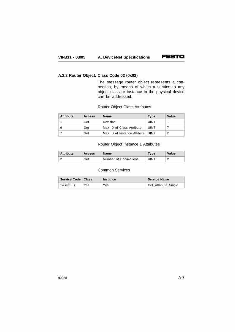
A.2.2 Router Object: Class Code 02 (0x02)
The message router object represents a con-nection, by means of which a service to anyobject class or instance in the physical devicecan be addressed.
Router Object Class Attributes
Attribute Access Name Type Value
1 Get Revision UINT 1
6 Get Max ID of Class Attribute UINT 7
7 Get Max ID of Instance Attibute UINT 2
Router Object Instance 1 Attributes
Attribute Access Name Type Value
2 Get Number of Connections UINT 2
Common Services
Service Code Class Instance Service Name
14 (0x0E) Yes Yes Get_Attribute_Single
VIFB11 - 03/05 A. DeviceNet Specifications
9902d A-7

A.2.3 DeviceNet Object: Class Code 03 (0x03)
DeviceNet Object Class Attributes
Attribute Access Name Type Value
1 Get Revision UINT 2
Router Object Instance 1 Attributes
Attribute Access Name Type Value
1 Get MACID USINT Rotary Switch
2 Get Baud Rate USINT DIP Switch
3 Get/Set Bus Off Interrupt** BOOL see 3**
4 Get/Set Bus Off Counter** USINT 0x00see 4**
5 Get/Set Allocation Information** STRUCT of AllocateServicesee 5**
Choice Byte BYTE
Master Node Addr. USINT
** Further explanations see next page
Common Services
Service Code Class Instance Service Name
14 (0x0E) Yes Yes Get_Attribute_Single
16 (0x10) No Yes Set_Attribute_Single
75 (0x4B) No Yes Allocate Master/Slave
76 (0x4C) No Yes Release Master/Slave
VIFB11 - 03/05 A. DeviceNet Specifications
A-8 9902d
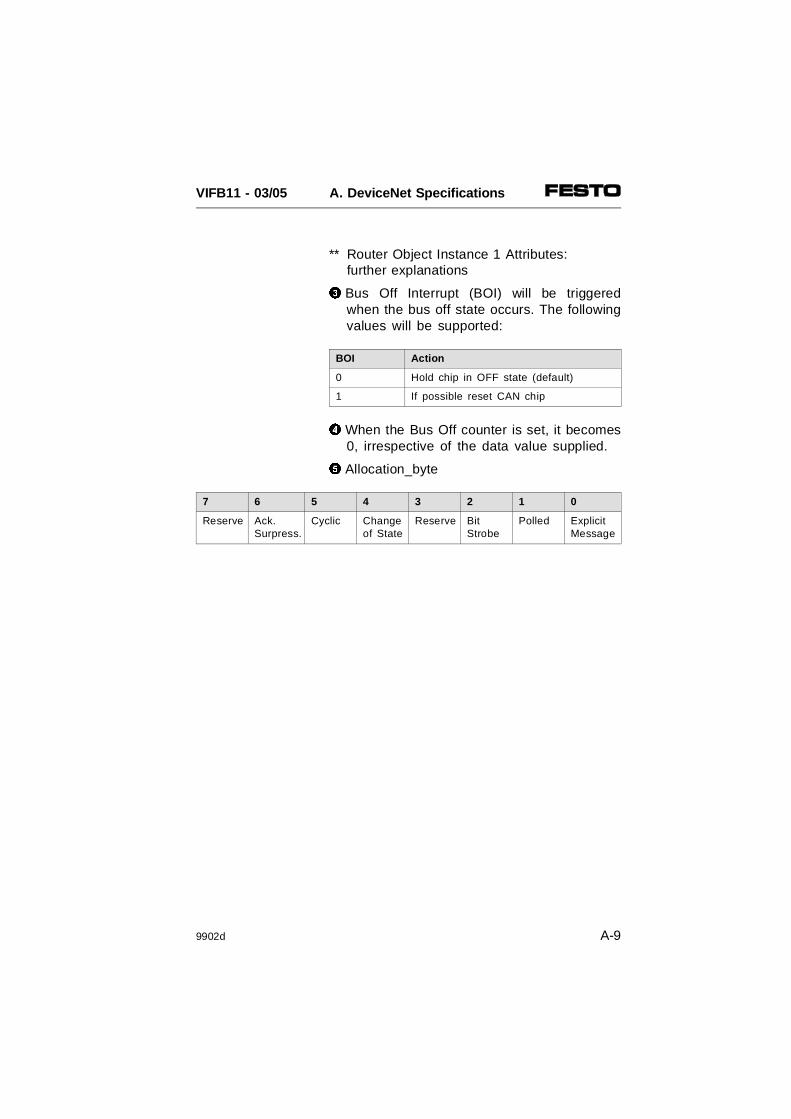
** Router Object Instance 1 Attributes: further explanations
3 Bus Off Interrupt (BOI) will be triggeredwhen the bus off state occurs. The followingvalues will be supported:
BOI Action
0 Hold chip in OFF state (default)
1 If possible reset CAN chip
4 When the Bus Off counter is set, it becomes0, irrespective of the data value supplied.
5 Allocation_byte
7 6 5 4 3 2 1 0
Reserve Ack.Surpress.
Cyclic Changeof State
Reserve BitStrobe
Polled ExplicitMessage
VIFB11 - 03/05 A. DeviceNet Specifications
9902d A-9

A.2.4 Assembly Object: Class Code 04 (0x04)
Two Instances of Assembly Object are sup-ported. Instance 1 is for input data andInstance 2 is for output data. The onlysupported assembly instance attribute is theValue Attribute (#3). The Get Service issupported for the assembly instances. SetService is supported for the output assembly.
Assembly Object Class Attributes
No class service supported
VIFB11 - 03/05 A. DeviceNet Specifications
A-10 9902d

Assembly Object Instance 1 Attribute 3
The following table shows the I/O Assemblydata attribute format for the input data contain-ing multiple discrete inputs (Discr Input 0...N)and multiple status inputs (Stat Input).
Instance Byte Bit 7 Bit 6 Bit 5 Bit 4 Bit 3 Bit 2 Bit 1 Bit 0
1 0 DiscrInput7
DiscrInput6
DiscrInput5
DiscrInput4
DiscrInput3
DiscrInput2
DiscrInput1
DiscrInput0
1 DiscrInput15
DiscrInput14
DiscrInput13
DiscrInput12
DiscrInput11
DiscrInput10
DiscrInput9
DiscrInput8
•••
K StatInputM
StatInputM-1
StatInput M-2
StatInputM-3
Discr. Input N...N-3or
Unused (0 to 3 bits)
The number of bytes 0...K used/allocated depends on the assembled I/O size ofthe valve terminal (see Chapter 4.1)
VIFB11 - 03/05 A. DeviceNet Specifications
9902d A-11
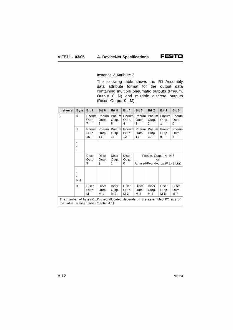
Instance 2 Attribute 3
The following table shows the I/O Assemblydata attribute format for the output datacontaining multiple pneumatic outputs (Pneum.Output 0...N) and multiple discrete outputs(Discr. Output 0...M).
Instance Byte Bit 7 Bit 6 Bit 5 Bit 4 Bit 3 Bit 2 Bit 1 Bit 0
2 0 PneumOutp.7
PneumOutp.6
PneumOutp.5
PneumOutp.4
PneumOutp.3
PneumOutp.2
PneumOutp.1
PneumOutp.0
1 PneumOutp.15
PneumOutp.14
PneumOutp.13
PneumOutp.12
PneumOutp.11
PneumOutp.10
PneumOutp.9
PneumOutp.8
•••
DiscrOutp.3
DiscrOutp.2
DiscrOutp.1
DiscrOutp.0
Pneum. Output N...N-3or
Unused/Rounded up (0 to 3 bits)
•••K-1
K DiscrOutp.M
DiscrOutp.M-1
DiscrOutp.M-2
DiscrOutp.M-3
DiscrOutp.M-4
DiscrOutp.M-5
DiscrOutp.M-6
DiscrOutp.M-7
The number of bytes 0...K used/allocated depends on the assembled I/O size ofthe valve terminal (see Chapter 4.1)
VIFB11 - 03/05 A. DeviceNet Specifications
A-12 9902d

Common Services
Service Code Class Instance Service Name
14 (0x0E) Yes Yes Get_Attribute_Single
16 (0x10) Yes Yes Set_Attribute_Single
A.2.5 Connection Object: Class Code 05 (0x05)
The Connection Objects manage the charac-teristics of each communication connection. Asa slave of group 2 the valve terminals onlysupport an explicit message connection as wellas a POLL message.
There are two instances of the ConnectionObject in the device. Instance #1 is assignedto the explicit messaging connection. Instance#2 is assigned to the Poll I/O Connection.
Connection Object Class Attributes
Attribute Access Name Type Value
1 Get Revision UINT 1
VIFB11 - 03/05 A. DeviceNet Specifications
9902d A-13

Connection Object Instance 1 Attributes (Explicit Message)
Attribute Access Name Type Value
1 Get State** USINT see 1**
2 Get Instance Type USINT 0 = Explicit Message
3 Get Transport Class Trigger USINT 0x83
4 Get Production Connection ID** UINT see 2**
5 Get Consumed Connection ID** UINT see 2**
6 Get Initial Comm. Char. USINT 0x21
7 Get Production Size UINT 07
8 Get Consumed Size UINT 07
9 Get/Set Expected Packet Rate UINT Apllication Dependent
12 Get/Set Timeout Action** USINT see 3**
13 Get Prod. Path Length USINT 0
14 Get Production Path** (zero) see 4**
15 Get Cons. Path Length USINT 0
16 Get Consumed Path** (zero) see 4**
** Further explanations see next page
VIFB11 - 03/05 A. DeviceNet Specifications
A-14 9902d

Connection Object Instance 2 Attributes (POLL connection)
Attribute
Access Name Type Value
1 Get State** USINT see 1**
2 Get Instance Type USINT 1 = I/O Message
3 Get Transport Class Trigger USINT 0x82
4 Get Production Connection ID** UINT see 2**
5 Get Consumed Connection ID** UINT see 2**
6 Get Initial Comm. Char. USINT 0x1
7 Get Production Size UINT number of Inp. bytes
8 Get Consumed Size UINT number of Outp. bytes
9 Get/Set Expected Packet Rate UINT
12 Get/Set Timeout Action** USINT see 3**
13 Get Prod. Path Length USINT 6
14 Get Production Path STRUCT of
Log. Seg., Class USINT 0x20
Class Number USINT 0x04 (Assembly)
Log.Seg., Instance USINT 0x24
Instance Number USINT 0x01 (Input)
Log.Seg., Attribute USINT 0x30
Attribute Number USINT 0x03
15 Get Cons. Path Length USINT 6
16 Get Consumed Path STRUCT of
Log. Seg., Class USINT 0x20
Class Number USINT 0x04 (Assembly)
Log.Seg., Instance USINT 0x24
Instance Number USINT 0x02 (Output)
Log.Seg., Attribute USINT 0x30
Attribute Number USINT 0x03
17 Get Production Inhibit UINT 0
VIFB11 - 03/05 A. DeviceNet Specifications
9902d A-15

Common Services
Service Code Class Instance Service Name
05 (0x05) Yes Yes Reset
14 (0x0E) Yes Yes Get_Attribute_Single
16 (0x10) No Yes Set_Attribute_Single
** Connection objects Attributes: further explanations
1 Connection States:0 = non-existent1 = configuring3 = established4 = timed out
2 Connection ID’s:Con. 1 Produced Con. ID: 10xxxxxx011Con. 1 Consumed Con. ID: 10xxxxxx100Con. 2 Produced Con. ID: 01111xxxxxxCon. 2 Consumed Con. ID: 10xxxxxx101 xxxxxx = Node Address.
3 Watch Dog TimeOut Activity:0 = Timeout (Explicit Messaging default)1 = Auto Delete2 = Auto Reset
4 If no data is available during the pollresponse, a 0 length (zero) packet isreturned.
VIFB11 - 03/05 A. DeviceNet Specifications
A-16 9902d

APPENDIX B
TECHNICAL APPENDIX
VIFB11 - 03/05 Appendix B
9902d B-1

Contents
B.1 TECHNICAL SPECIFICATIONS B-3General B-3Operating voltage electronic components and inputs B-4Operating voltage outputs/valves B-4Operating voltage of bus interface B-5Field bus B-5Electromagnetic compatibility (EMC) B-6
B.2 CABLE LENGTH AND CROSS-SECTIONAL AREA B-7Calculating with a graph B-8Calculating with a formula B-10
B.3 EXAMPLES OF CIRCUITRY B-12Operating voltage connection type 03 B-12Operating voltage connection type 05 B-13
B.4 ACCESSORIES B-14Bus connection B-14
B.5 DEVICENET COMPATIBILITY - CONFIGURATION OF SOFTWAREVERSION V1.3/1.4 B-17EDS library: Entering slaves manually B-18
VIFB11 - 03/05 Appendix B
B-2 9902d

B.1 TECHNICAL SPECIFICATIONS
General
Protection class(as per DIN 40050)
Temperature during• operation• storage/transport
IP 65
- 5 oC . . . +50 oC-20 oC . . . +60 oC
Vibrations(as per DIN/IEC 68 part 2-6and IEC 721/part 2-3)• Transport
• Operation
Shock(as per DIN/IEC 68 part 2-27and IEC 721)
3.5 mm path at 2-8 Hz1 g accelerationat 8-25 Hz
3.5 mm pathat 25-57 Hz5 g accelerationat 57-150 Hz and1 g accelerationat 150-200 Hz
30 g at 11 ms
VIFB11 - 03/05 Appendix B
9902d B-3

Operating voltage electronic components and inputs
(Pin 1 – operating voltage connection)• Rated value
(protected against incorrect polarity)
• Tolerance
• Residual ripple• Current consumption
(at 24 V)
• Fuse for supply to inputs/sensors
Power consumption (P)• Calculation
24 V DC
± 25 %(18 V . . . 30 V DC)4Vpp200 mA + sum of current consumption of electrical inputsinternal 2 A, slow blowing
P[W] = (0.2 A +
∑ I Inputs) ⋅ 24 V
Bridging time iflogic voltage drops
min. 20 ms
Operating voltage outputs/valves
(Pin 2 – operatingvoltage connection)• Rated value
(protected against incorrect polarity)
• Tolerance
• Residual ripple• Current consumption
(at 24 V)
Power consumption (P)• Calculation
external fuse required 24 V DC (typ. 10 A)
± 10 %(21.6 V ... 26.4 V DC)4 Vpp10 mA + Sum of current
consumption ofelectric outputs
+ Sum of currentconsumption ofthe switched valve solenoid coils (e.g. per MIDI valvesolenoid coil 55 mA
P[W] = (0.01 A +∑ Ielectric outputs +
∑ Isolenoid coil) ⋅ 24 V
VIFB11 - 03/05 Appendix B
B-4 9902d

Operating voltage of bus interface
(Pin 2,3 – bus interface)
• Rated value• Not protected against
short circuit• Tolerance
• Current consumption(at 24 V)
external fuse
24 V DC
+ 4% - 52%(Vmax 25 V, Vmin 11.5 V50 mA
Field bus
Design ISO 11898
Transmission type serialasynchronous, half-duplex
Protocol • Allen-BradleyDeviceNet
• Philips DIOS• Selectron SELECAN
Baud rate depends on protocol
Cable length(depending on baud rateand cable type)
1000 m
Cable type(depending on cable lengthand field bus baud rate set)
see controller manual
VIFB11 - 03/05 Appendix B
9902d B-5

Please refer to the Pneumatics Manual fortechnical specifications on the pneumatic com-ponents and valves.
Please refer to the supplementary descriptionof the I/O modules for the technical specifica-tions of the I/O modules.
Electromagnetic compatibility (EMC)
Interference radiated• tested as per EN 55011
Resistance to interference• tested as per EN 50082-2
Limit class B
Protection against electricshock (Protection against direct and indirect contactas per EN 60204-1/IEC 204)
By means of PELVpower units (Protectedextra low voltage)
VIFB11 - 03/05 Appendix B
B-6 9902d

B.2 CABLE LENGTH AND CROSS-SECTIONAL AREA
PLEASE NOTEThe following information is for the exclusiveuse of personnel trained in electrotechnologyand who are already familiar with the contentsof the chapters on "Installation" in this manual.
A load-dependent drop in voltage occurs on allthree cables for the operating voltage supply toa valve terminal. This can cause the voltage atpin 1 or 2 of the operating voltage connectionto be outside the permitted tolerances.
Recommendation
• Avoid long distances between the powerunit and the terminal.
• Calculate suitable cable lengths and cross-sec-tional areas in accordance with the followinggraph or formulae. Please note that:– the graph supplies approximate values for the cross-sectional areas 1.5 and
2.5 mm2.– the formulae supply exact values for
any cross sectional area .
PLEASE NOTEThe following graphs and formulae require thatthe cross-sectional areas of the operating volt-age supply cables (pins 1, 2 and 3) are thesame.
VIFB11 - 03/05 Appendix B
9902d B-7

Calculating with a graph
Proceed as follows:
1. Calculate the maximum current consumptionof the output/valves (I2).
2. Calculate the lowest voltage to be expectedon the power unit during operation (VOmin).Take into consideration:• the influence of load variation on the power
unit• the fluctuations in the primary mains
voltage.
3. Read the permitted length of cable in thetable for the relevant sectional area.Example for 1.5 mm2:VOmin = 22.8 V, I2 = 2 A; Lmax = 25 m
VIFB11 - 03/05 Appendix B
B-8 9902d

10A 6A4A
21.6
10 20 30 40 50 m
+10%
-10%
26.4
2A
8A
3A
0
12A14A
22
23
24
25
26
VOmin in voltV
Current I2 in ampere
Cable length in metres
Sectional area 1.5 mm 2
+10% 12A14A
21.6
10 20 30 40 50 m
-10%
26.4
0
10A 8A
6A
4A
3A
2A
22
23
24
25
26
VOmin in voltV
Current I2 in ampere
Cable length in metres
Sectional area 2.5 mm 2
VIFB11 - 03/05 Appendix B
9902d B-9

Calculating with a formula
Proceed as follows:
1. Calculate the maximum current consumptionof the inputs and electronic components (I1)as well as of the outputs/valves (I2).
2. Calculate the lowest voltage to be expectedon the power unit during operation (VOmin).Take into consideration:• the influence of load variation on the
power unit• the fluctuations in the primary mains
voltage.
3. Enter the values in the appropriate formula.The equivalent circuit diagram and theexample explain the relations.
AC
DC
VO
*)
3.15 AT
10 AT
I1
I2
Pin 1Pin 2
Pin 3
Valveterminal
RL0
0 V
VL2 + VL1
Vterminal
Lineresistance(outgoing)
RI2RI1
VO
RL1
Line resistance(returning)
VL1VL2RL2
Distance (cable length)L
Operating voltage supply Replacement circuit diagram
I0
*) load voltage can be switched off separately
Fig. B/1: Cable length (L) and line resistance (RL)
VIFB11 - 03/05 Appendix B
B-10 9902d

Formula for calculating cable lengths
L ≤ (VOmin − VTERMINALmin) ⋅ A ⋅ κCu
2 ⋅ I2 + I1
This means:
• VTERMINAL = 24 V ± 10%, minimum: VTERMINALmin ≥ 21.6 V
• VOmin = minimum operating voltagesupply (at power unit)
• Current I1 = Current for electronic compo-nents and inputs
• Current I2 = Current for outputs/valves
• A = Cable cross-sectional area (uniform e.g. 1.5 mm2)
• κ = Conductivity value of cables
(uniform e.g. κCu = 56 m
mm 2 ⋅ Ω )
Example I1 = 1 A; I2 = 5 A; VOmin = 24 V; VTERMINALmin = 21.6 V ;
κCu = 56 m
mm 2 ⋅ Ω;
ResultL ≤ 18 m for A = 1.5 mm2
L ≤ 30 m for A = 2.5 mm2
VIFB11 - 03/05 Appendix B
9902d B-11

B.3 EXAMPLES OF CIRCUITRY
Operating voltage connection type 03
Pinassignment(node)
Circuitryexample andinternalstructure
Fig. B/2a:Circuitry example – operating voltage type 03
230 V
Power unit (central powersupply)
AC
DC
3.15 A
10 A
24 V ± 10 %
24 V ± 10 %
0 V
Electricinputs/sensors (fused internally)
Valves (must befused externally)
Electric outputs
24 V electroniccomponents (fusedinternally)
2 A
Operating voltageconnection for valveterminal
*)
PE Potential compensation
*) load voltage can be switched off separately
2: 24 V supply tooutputs/valves
3: 0 V4: Earth connection
1: 24 V supplyto electronic components
VIFB11 - 03/05 Appendix B
B-12 9902d
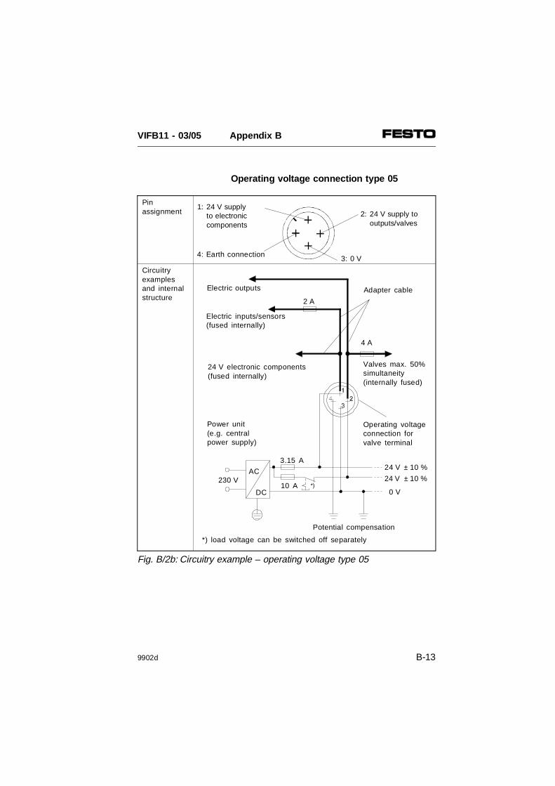
Operating voltage connection type 05
Fig. B/2b: Circuitry example – operating voltage type 05
230 V
Power unit (e.g. central power supply)
AC
DC
3.15 A
10 A
24 V ± 10 %
24 V ± 10 %
0 V
Electric inputs/sensors (fused internally)
Adapter cableElectric outputs
24 V electronic components(fused internally)
2 A
Operating voltageconnection for valve terminal
*)
4 A
Valves max. 50%simultaneity(internally fused)
Potential compensation
*) load voltage can be switched off separately
Pinassignment
Circuitryexamplesand internalstructure
2: 24 V supply tooutputs/valves
3: 0 V4: Earth connection
1: 24 V supplyto electronic components
VIFB11 - 03/05 Appendix B
9902d B-13
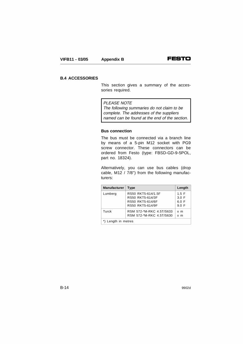
B.4 ACCESSORIES
This section gives a summary of the acces-sories required.
PLEASE NOTEThe following summaries do not claim to becomplete. The addresses of the suppliersnamed can be found at the end of the section.
Bus connection
The bus must be connected via a branch lineby means of a 5-pin M12 socket with PG9screw connector. These connectors can beordered from Festo (type: FBSD-GD-9-5POL,part no. 18324).
Alternatively, you can use bus cables (dropcable, M12 / 7/8") from the following manufac-turers:
Manufacturer Type Length
Lumberg RS50 RKT5-614/1.5F RS50 RKT5-614/3F RS50 RKT5-614/6F RS50 RKT5-614/9F
1.5 F 3.0 F 6.0 F 9.0 F
Turck RSM 572-*M-RKC 4.5T/S633RSM 572-*M-RKC 4.5T/S630
x m x m
*) Length in metres
VIFB11 - 03/05 Appendix B
B-14 9902d

The branch line can be connected to the busby means of a T-adapter (T-tap). The followingT-taps are available to suit the bus cablesnamed.
Manufacturer Type
Lumberg TAP 50-RK
Turck RSM-2RKM 57
Woodhead DN 3000
The following manufacturers offer T-adapterswith screw terminals.
Manufacturer Type
Phillips BR50
Selectron CTA 701
Addresses:
Manufacturer Addresses
Woodhead Industries Inc.
United StatesDaniel Woodhead3411 Woodhead DriveNorthbrook, Illinois 60062
CanadaWoodhead Canada Ltd. Company1090 Brevik PlaceMississauga, OntarioCanada L4W 3Y5
United KingdomAero-Motive (U.K.) Ltd.9. Rassau Industrial EstateEbbw Vale, Gwent,NP3 5SD, U.K
GermanyH. F. Vogel GmbHTullastrasse 9 75196 Remchingen
VIFB11 - 03/05 Appendix B
9902d B-15

Manufacturer AddressesLumberg United States
Lumberg Inc.11351 Business Center DriveUSA-Richmond,VA 23236
United KingdomLumberg (U.K.) Ltd.The Mount, HighclereNewbury, Berkshire,RG 20 9QZ
GermanyLumberg GmbH & Co.Hälverstraße 94D-58579 Schalksmühle
Turck United StatesTURCK Inc.3000 Campus DriveUSA-Plymouth,MN 55441-2656United KingdomMTE TURCK Ltd.Stephenson RoadLeigh-on-Sea,Essex SS9 5LS
GermanyHans Turck Gmbh & Co.KGWitzlebenstraße 7D-45472 Mülheim an der Ruhr
Philips NetherlandsPMA NederlandGebouw TQIII-4Postbus 80025NL-5600 JZ Eindhoven
GermanyPhilips Industrial Electrionics DeutschlandMiramstraße 87D-34123 Kassel
Selectron SwitzerlandSelectron Lyss AG Industrielle ElektronikBernstrasse 70CH-3250 Lyss
GermanySelectron System GmbHSchupfer Strasse 1Postfach 31 02 62D-90202 Nürnberg
VIFB11 - 03/05 Appendix B
B-16 9902d
B.5 DEVICENET COMPATIBILITY - CONFIGURATION OF SOFTWARE VERSION V1.3/1.4
With DIL switch 4, you can switch field busnode IFB11-03 as from version V2.0 (26.02.99)to the old software version (software statusV1.3/1.4 from 22.07.96 or earlier) and thereby-create compatibility with existing configuredDeviceNet networks.
PLEASE NOTEIn the case of field bus nodes with softwarestatus V1.3/1.4 (22.07.96 or earlier) somesteps necessary for configuration in the De-viceNet Manager must be carried out differ-ently from the new version V2.0.1. Set compatibility with the earlier version in
the node with software version V2.0(26.02.99) in accordance with Chapter 3.2,"Setting the compatibility.”
2. Then enter the valve terminal manually inthe DeviceNet Manager in accordance withthe following section.
VIFB11 - 03/05 Appendix B
9902d B-17
EDS library: Entering slaves manually
When you commission a valve terminal withthe DeviceNet Manager the first time , youmust first extend the EDS library (electronicdata sheets) of the DeviceNet Manager. Infor-mation on the valve terminal, such as thename of the manufacturer, the product name,product code etc. are entered here in the EDSlibrary.
The necessary information can be:
• read in online mode• entered in offline mode.
Please note that the product code of themodular valve terminal up to softwareversion V1.3/1.4 (22.07.96) depends on theequipment fitted on the valve terminal .Valve terminals with different equipment fittedhave different product codes.
VIFB11 - 03/05 Appendix B
B-18 9902d

PLEASE NOTEIf necessary, you can read the actual productcode of your valve terminal in online modewith the function "Network Who" or "CreateEDS Stub..." and "Load Description from Device" etc.
In order to extend the EDS library, you mustactivate the function Create EDS Stub... in themenu Utilities. The dialogue box Create EDSStub will then appear.
Fig. B/3: Dialogue box "Create EDS Stub"
VIFB11 - 03/05 Appendix B
9902d B-19

In order to extend the EDS library offline:
1. Open the list field Vendor Name. You willthen see a selection of firm names. SelectFesto Corporation or if Festo is not listed,open the dialogue box Add Vendor. Enter thenumber 26 under Vendor ID and "Festo" asVendor Name. Then close the dialogue box.
2. Open the dialogue box Add Type. Enter thenumber 25 under Device type ID and "Pneu-matic valves" or "Valve terminal/manifold" asDevice Type. Then close the dialogue box.
3. Enter the individually ascertained decimalvalue for your valve terminal in the field Product Code.
PLEASE NOTE– You must create a separate individual
EDS file for valve terminals with differentI/O bytes.
– After extension/conversion of a valveterminal, check whether the I/O byteshave been modified, whereupon they willhave to calculate the Product Code again.
VIFB11 - 03/05 Appendix B
B-20 9902d

Calculate the value for the Product Code asfollows:
• Calculate the number of input bytes andoutput bytes of the valve terminal inaccordance with Chapter 4.1 (rounded up tofull bytes).
• Compile the Product Code first as a four-fig-ure, hexadecimal number as follows:xyI/O (hex), whereby: x = number of input bytes, y = number ofoutput bytesexample: valve terminal with 2 input bytes and 6output bytes: 26I/O (hex)
• Now convert the Product Code to a decimalnumber. example: 26I/O (hex) ⇒ (9962 (dez)
• Enter this individual Product Code as adecimal number in the appropriate EDS filefor each valve terminal.
VIFB11 - 03/05 Appendix B
9902d B-21

4. Enter the number "1" in the field Major Revi-sion and number "3" in the field Minor Revi-sion.
5. Enter "IFB11-03/5&xyEA" (see 3.) under Pro-duct Name.
6. Activate the entry Enable under Polled Con-nection.
PLEASE NOTEThe Festo valve terminal only supports themode Polled Connection .
7. Recommendation:Enter the number of I/O bytes calculated forinput/output size under Polled Connection.
8. If you wish to install the Festo icon of valveterminal type 03:– Insert the CD ROM "Utilities."– Open the dialogue box Browse under Select Bitmaps for this Device.– You can now load either the file "DNF11io.bmp" (Valve terminal no. of I/Os) or "DN F11vv.bmp" (Valve terminal) from the CD ROM.
9. Save the values with OK. The entries will thenbe transferred to the EDS library.
VIFB11 - 03/05 Appendix B
B-22 9902d
In order to extend the EDS library online:
1. Activate the field Load from Device in the dia-logue box Create EDS Stub.
2. Enter the station number (device node ad-dress) of the valve terminal in the field LoadDescription from Device and confirm the entrywith OK. The necessary information will thenbe read and entered.
PLEASE NOTELeave the value shown in the field ProductCode andMajor/Minor Revision unchanged.
3. Enter "IFB11-03/5&xyEA" under ProductName (xy = exact number of I/O bytes)
4. Activate the entry Enable under Polled Con-nection.
PLEASE NOTEThe Festo valve terminal only supports the mode Polled Connection .
VIFB11 - 03/05 Appendix B
9902d B-23

5. Recommendation:Enter the exact number of I/O bytes calcu-lated for input/output size under Polled Con-nection (see chapter 4.1). If necessary, roundup to full bytes.
6. If you wish to install the Festo icon of valveterminal type 03:– Insert the CD ROM "Utilities."– Open the dialogue box Browse under Select Bitmaps for this Device.– You can now load either the file "DNF11io.bmp" (Valve terminal with I/O modules) or "DN F11vv.bmp" (Valve terminal without I/O modules) from the CD ROM.
7. Save the values with OK. The entries will thenbe transferred to the EDS library.
When you have successfully extended yourEDS library, you can extend your network witha valve terminal V1.3/1.4 (see chapter 4.2.3,section "Extending the network with a valveterminal").
VIFB11 - 03/05 Appendix B
B-24 9902d

APPENDIX C
INDEX
VIFB11 - 03/05 Appendix C
9902d C-1

VIFB11 - 03/05 Appendix C
C-2 9902d

AAbbreviations . . . . . . . . . . . . . . . . . . . . . . . . . XIVAccessories
manufacturer . . . . . . . . . . . . . . . . . . . . . B-15Addressing
basic rule 1. . . . . . . . . . . . . . . . . . . . . . . . 4-12basic rule 2. . . . . . . . . . . . . . . . . . . . . . . . 4-15basic rule 3. . . . . . . . . . . . . . . . . . . . . . . . 4-15Philips DIOS. . . . . . . . . . . . . . . . . . . . . . . 4-22Selectron Selecan . . . . . . . . . . . . . . . . . . 4-36
BBaud rate . . . . . . . . . . . . . . . . . . . . . . . . . . . . 3-14
PLEASE NOTEThe index is based on key words. It thereforesupplements the contents which are based ona function/action-orientated grouping.
In the index you will not therefore find "Con-necting the operating voltage", but the separ-ate entries "Connections" and "Voltage".
VIFB11 - 03/05 Appendix C
9902d C-3
CCable
connecting to plugs/sockets. . . . . . . . . . . . 3-6field bus . . . . . . . . . . . . . . . . . . . . . . 3-4, 3-32operating voltage . . . . . . . . . . . 3-4, 3-27, B-7selecting . . . . . . . . . . . . . . . . . . . . . . . 3-4, B-7
Calculating the weight . . . . . . . . . . . . . . . . . . 2-12Connections
valves . . . . . . . . . . . . . . . . . . . . . . . . . . . . . 1-7Connections, valves . . . . . . . . . . . . . . . . 1-5, 1-9Current
calculating for type 03 . . . . . . . . . . . . . . . 3-21fuses. . . . . . . . . . . . . . . . . . . . . . . . 3-23, 3-31selecting the cable . . . . . . . . . . . . . . 3-27, B-7
Current consumption . . . . . . . . . . . . . . . . . . . 3-21
DData transmission
interface . . . . . . . . . . . . . . . . . . . . . 3-32, 3-35Diagnosis
diagnostic word . . . . . . . . . . . . . . . . . . . . 5-12LEDs. . . . . . . . . . . . . . . . . . . . . . . . . . . . . . 5-4Philips DIOS. . . . . . . . . . . . . . . . . . . . . . . 4-25Selectron Selecan . . . . . . . . . . . . . . . . . . 4-39status bits . . . . . . . . . . . . . . . . . . . . . . . . . 5-12
Diagnostic possibilities. . . . . . . . . . . . . . . . . . . 5-3DIL switch . . . . . . . . . . . . . . . . . . . . . . . . . . . 3-13
VIFB11 - 03/05 Appendix C
C-4 9902d
EEarthing
components . . . . . . . . . . . . . . . . . . . 2-6 - 2-7valve terminal . . . . . . . . . . . . . . . . . 3-22, 3-29
EDS file . . . . . . . . . . . . . . . . . . . . . . . . . . . . . 4-42EMERGENCY STOP concept. . 3-19, 3-26, 3-31Error
short circuit output module. . . . . . . . . . . . 5-16treatment . . . . . . . . . . . . . . . . . . . . . . . . . . 5-3
FFastening eyes . . . . . . . . . . . . . . . . . . 2-10, 2-13Field bus
baud rate . . . . . . . . . . . . . . . . . . . . . . . . . 3-14interface . . . . . . . . . . . . . . . . . . . . . . . . . . 3-32module . . . . . . . . . . . . . . . . . . . . . . . . . . . XVInode . . . . . . . . . . . . . . . . . . . . . . . . . . . . . 1-11protocol. . . . . . . . . . . . . . . . . . . . . . . . . . . 3-15station number . . . . . . . . . . . . . . . . . . . . . 3-11
Functionnode . . . . . . . . . . . . . . . . . . . . . 1-8, 1-11, 3-9valve terminal . . . . . . . . . . . . . . . . . . . 1-3, 1-8
Fusesexternal. . . . . . . . . . . . . . . . . 3-23, 3-31, B-12internal . . . . . . . . . . . . . . . . . 3-9, B-12 - B-13
HHat rail
clamping unit . . . . . . . . . . . . . . . . . . . . . . 2-10
VIFB11 - 03/05 Appendix C
9902d C-5

ISwitching status. . . . . . . . . . . . . . . . . . . . . . . . 5-9
LLED display
node . . . . . . . . . . . . . . . . . . . . . . . . . . . . . 3-10valves . . . . . . . . . . . . . . . . . . . . . . . . . . . . . 5-7
NNode . . . . . . . . . . . . . . . . . . . . . . . . . . . . . . . 1-11
OOperating voltage
selecting the cable . . . . . . . . . . . . . . . . . . . 3-5Switching status. . . . . . . . . . . . . . . . . . . . . . . . 5-9
PPin assignment
field bus/DeviceNet . . . . . . . . . . . . . . . . . 3-32fieldbus/DeviceNet . . . . . . . . . . . . . . . . . . 3-32operating voltage . . . . . . . . . . . . . . . . . . . 3-22
Protocol . . . . . . . . . . . . . . . . . . . . . . . . . . . . . 3-15
VIFB11 - 03/05 Appendix C
C-6 9902d
SScreening
field bus . . . . . . . . . . . . . . . . . . . . . . . . . . 3-35Setting the field bus baud rate . . . . . . . . . . . 3-14Short circuit
eliminate . . . . . . . . . . . . . . . . . . . . . . . . . . 5-16fuses. . . . . . . . . . . . . . . . . . . . . . . . 3-23, B-12
Station numbers . . . . . . . . . . . . . . . . . . . . . . 3-12Status bits
diagnostic information . . . . . . . . . . . . . . . 5-12System structure . . . . . . . . . . . . . . . . . . . . . . . 1-3
TTechnical specifications. . . . . . . . . . . . . . . . . B-3
VVoltage
connecting . . . . . . . . . . . . . . . . . . . 3-18, 3-22connecting the field bus . . . . . . . . . 3-35, 3-40connecting type 05. . . . . . . . . . . . . 3-25, 3-29selecting the cable . . . . . . . . . . . . . 3-20, 3-27selecting the power unit . . . . 3-20, 3-27 - 3-28switching on . . . . . . . . . . . . . . . . . . . . . . . . 4-6
VIFB11 - 03/05 Appendix C
9902d C-7

VIFB11 - 03/05 Appendix C
C-8 9902d