MIL-STD-1553 BUS CONTROLLER TERMINAL
13
Ancy Das et al IJMEIT Volume 2 Issue 3 March 2014 Page 153 IJMEIT// Vol. 2 Issue 3//March 2014 //Page No: 153-165//e-ISSN: 2348-196x 2014 MIL-STD-1553 BUS CONTROLLER TERMINAL Ancy Das 1 , Aravindhan A 2 , Lekshmi K R,Avionics 3 1 A S, PG Student, ECE Department Saintgits College of Engineering,Kottayam. 2 Asst.Professor, ECE Department, Saintgits College of Engineering, Kottayam. Dept,VSSC,Trivandrum. Email: [email protected] Abstract— MIL-STD-1553 has evolved into the predominant, internationally accepted networking standard for the integration of military platforms. Today, the standard has expanded beyond its traditional domain of US Air Force and Navy aircraft to encompass applications for combat vehicles, ships, satellites, missiles, and the International Space Station Program, as well as advanced commercial avionic applications. Once considered primarily a military data bus standard, MIL-STD-1553 has caught the attention of commercial aircraft manufacturers who seek to capitalize upon the standard’s inherent reliability, robustness, maturity, and superior EMI performance. Despite the recent advent of newer and higher-speed technologies, it is clearly evident that 1553 will continue to be used extensively in evolving upgrade programs as well as for new applications and integration platforms for years to come.MIL-STD-1553 is a military standard that defines the electrical and protocol characteristics for a data bus. A data bus is used to provide a medium for the exchange of data and information between various systems. It is similar to what the personal computer and office automation industry has dubbed a Local Area Network (LAN).In this project introduction to the MIL-STD-1553 data bus, its history, working, applications and use is studied. Project describes the physical elements that make up the bus, the protocol, including the message formats, word types, and command and status words of MIL-STD-1553 Data bus and implementation of MIL-STD-1553 Bus Controller terminal and its information transfer (message) formats is coded using Modelsim. I. INTRODUCTION MIL-STD: A United States defense standard, often called a military standard, "MIL-STD", "MIL-SPEC", or (informally) "MilSpecs", is used to help achieve standardization objectives by the U.S Department of Defense. Standardization is beneficial in achieving interoperability, ensuring products meet certain requirements, commonality, reliability, total cost of ownership and compatibility with logistics systems. Defense standards are also used by other non-defense government organizations, technical organizations and industry.
Transcript of MIL-STD-1553 BUS CONTROLLER TERMINAL

Ancy Das et al IJMEIT Volume 2 Issue 3 March 2014 Page 153
IJMEIT// Vol. 2 Issue 3//March 2014 //Page No: 153-165//e-ISSN: 2348-196x 2014
MIL-STD-1553 BUS CONTROLLER TERMINAL
Ancy Das1, Aravindhan A
2, Lekshmi K R,Avionics
3
1A S, PG Student, ECE Department Saintgits College of Engineering,Kottayam. 2Asst.Professor, ECE Department, Saintgits College of Engineering, Kottayam.
Dept,VSSC,Trivandrum.
Email: [email protected]
Abstract—
MIL-STD-1553 has evolved into the predominant, internationally accepted networking standard for
the integration of military platforms. Today, the standard has expanded beyond its traditional
domain of US Air Force and Navy aircraft to encompass applications for combat vehicles, ships,
satellites, missiles, and the International Space Station Program, as well as advanced commercial
avionic applications. Once considered primarily a military data bus standard, MIL-STD-1553 has
caught the attention of commercial aircraft manufacturers who seek to capitalize upon the
standard’s inherent reliability, robustness, maturity, and superior EMI performance. Despite the
recent advent of newer and higher-speed technologies, it is clearly evident that 1553 will continue
to be used extensively in evolving upgrade programs as well as for new applications and
integration platforms for years to come.MIL-STD-1553 is a military standard that defines the
electrical and protocol characteristics for a data bus. A data bus is used to provide a medium for
the exchange of data and information between various systems. It is similar to what the personal
computer and office automation industry has dubbed a Local Area Network (LAN).In this project
introduction to the MIL-STD-1553 data bus, its history, working, applications and use is studied.
Project describes the physical elements that make up the bus, the protocol, including the message
formats, word types, and command and status words of MIL-STD-1553 Data bus and
implementation of MIL-STD-1553 Bus Controller terminal and its information transfer (message)
formats is coded using Modelsim.
I. INTRODUCTION
MIL-STD:
A United States defense standard, often called
a military standard, "MIL-STD", "MIL-SPEC", or
(informally) "MilSpecs", is used to help achieve
standardization objectives by the U.S Department of
Defense. Standardization is beneficial in
achieving interoperability, ensuring products meet
certain requirements, commonality, reliability, total
cost of ownership and compatibility
with logistics systems. Defense standards are also
used by other non-defense government
organizations, technical organizations and industry.
Ancy Das et al IJMEIT Volume 2 Issue 3 March 2014 Page 154
IJMEIT// Vol. 2 Issue 3//March 2014 //Page No: 153-165//e-ISSN: 2348-196x 2014
Defense standards evolved from
the need to ensure proper performance,
maintainability and reparability and logistical
usefulness of military equipment. In the late 18th
century and throughout the 19th,
the American and French militaries were early
adopters and long time developmental sponsors and
advocates of interchangeability and standardization.
By World War II (1939-1945), virtually all
national militaries and trans-national alliances of the
same (Allied Forces, Axis powers) were busy
standardizing and cataloguing. The U.S. AN-
cataloguing system (Army-Navy) and the British
Defence Standards (DEF-STAN) provide
examples..
MIL-STD-1553 Data Bus:
In the 1950s and 1960s, aviation electronics,
referred to as avionics, were simple stand-alone
systems. The navigation, communications, flight
controls, and displays consisted of analog systems.
Often these systems were composed of multiple
boxes, or subsystems, connected to form a single
system.
By the late 1960s and early 1970s, it
became necessary to share information between the
various systems to reduce the number of black
boxes required by each system. As the system used
point-to-point wiring, the system that was the
source of the signal typically had to be modified to
provide the additional hardware to output to the
newly added subsystem. As such, inter-system
connections had to be kept to the bare minimum.
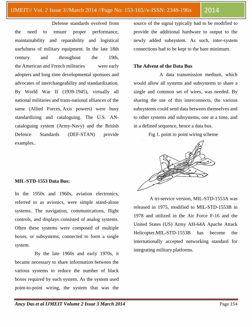
The Advent of the Data Bus
A data transmission medium, which
would allow all systems and subsystems to share a
single and common set of wires, was needed. By
sharing the use of this interconnects, the various
subsystems could send data between themselves and
to other systems and subsystems, one at a time, and
in a defined sequence, hence a data bus.
Fig 1. point to point wiring scheme
A tri-service version, MIL-STD-1553A was
released in 1975, modified to MIL-STD-1553B in
1978 and utilized in the Air Force F-16 and the
United States (US) Army AH-64A Apache Attack
Helicopter.MIL-STD-1553B has become the
internationally accepted networking standard for
integrating military platforms.
Ancy Das et al IJMEIT Volume 2 Issue 3 March 2014 Page 155
IJMEIT// Vol. 2 Issue 3//March 2014 //Page No: 153-165//e-ISSN: 2348-196x 2014
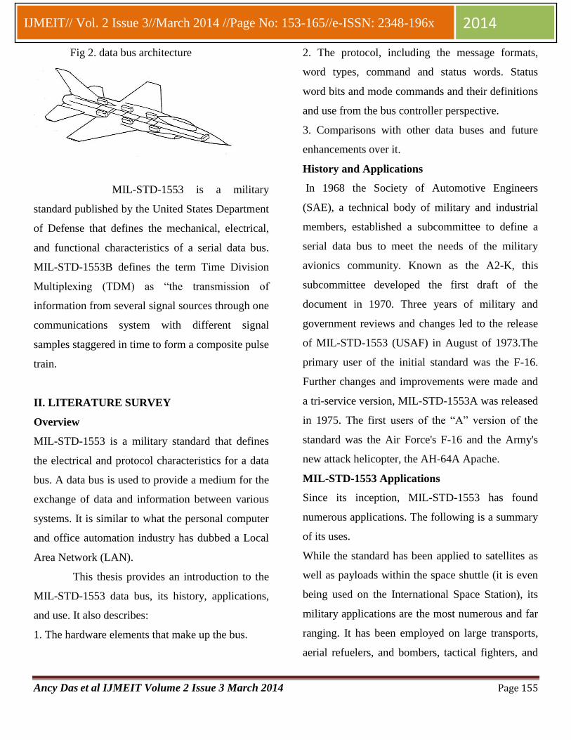
Fig 2. data bus architecture
MIL-STD-1553 is a military
standard published by the United States Department
of Defense that defines the mechanical, electrical,
and functional characteristics of a serial data bus.
MIL-STD-1553B defines the term Time Division
Multiplexing (TDM) as “the transmission of
information from several signal sources through one
communications system with different signal
samples staggered in time to form a composite pulse
train.
II. LITERATURE SURVEY
Overview
MIL-STD-1553 is a military standard that defines
the electrical and protocol characteristics for a data
bus. A data bus is used to provide a medium for the
exchange of data and information between various
systems. It is similar to what the personal computer
and office automation industry has dubbed a Local
Area Network (LAN).
This thesis provides an introduction to the
MIL-STD-1553 data bus, its history, applications,
and use. It also describes:
1. The hardware elements that make up the bus.
2. The protocol, including the message formats,
word types, command and status words. Status
word bits and mode commands and their definitions
and use from the bus controller perspective.
3. Comparisons with other data buses and future
enhancements over it.
History and Applications
In 1968 the Society of Automotive Engineers
(SAE), a technical body of military and industrial
members, established a subcommittee to define a
serial data bus to meet the needs of the military
avionics community. Known as the A2-K, this
subcommittee developed the first draft of the
document in 1970. Three years of military and
government reviews and changes led to the release
of MIL-STD-1553 (USAF) in August of 1973.The
primary user of the initial standard was the F-16.
Further changes and improvements were made and
a tri-service version, MIL-STD-1553A was released
in 1975. The first users of the “A” version of the
standard was the Air Force's F-16 and the Army's
new attack helicopter, the AH-64A Apache.
MIL-STD-1553 Applications
Since its inception, MIL-STD-1553 has found
numerous applications. The following is a summary
of its uses.
While the standard has been applied to satellites as
well as payloads within the space shuttle (it is even
being used on the International Space Station), its
military applications are the most numerous and far
ranging. It has been employed on large transports,
aerial refuelers, and bombers, tactical fighters, and
Ancy Das et al IJMEIT Volume 2 Issue 3 March 2014 Page 156
IJMEIT// Vol. 2 Issue 3//March 2014 //Page No: 153-165//e-ISSN: 2348-196x 2014
helicopters. It is even contained within missiles and
serves, in some instances, as the primary interface
between the aircraft and a missile. The Navy has
applied the data bus to both surface and subsurface
ships. The Army, in addition to its helicopters, has
put 1553 into tanks and howitzers.
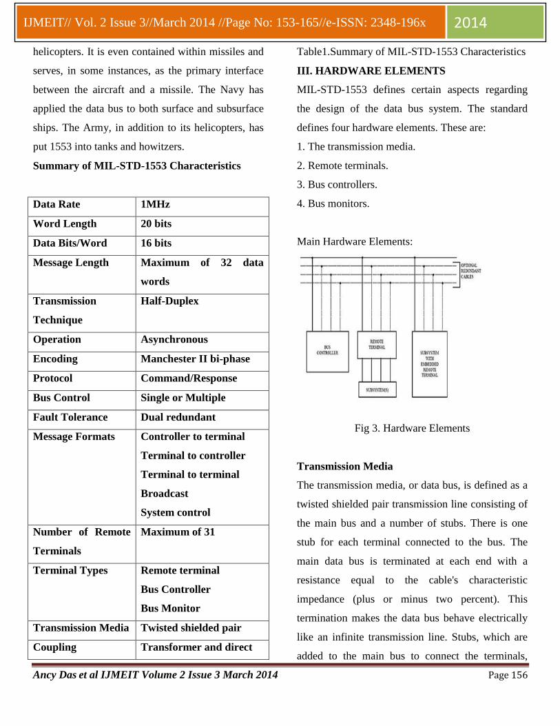
Summary of MIL-STD-1553 Characteristics
Data Rate 1MHz
Word Length 20 bits
Data Bits/Word 16 bits
Message Length Maximum of 32 data
words
Transmission
Technique
Half-Duplex
Operation Asynchronous
Encoding Manchester II bi-phase
Protocol Command/Response
Bus Control Single or Multiple
Fault Tolerance Dual redundant
Message Formats Controller to terminal
Terminal to controller
Terminal to terminal
Broadcast
System control
Number of Remote
Terminals
Maximum of 31
Terminal Types Remote terminal
Bus Controller
Bus Monitor
Transmission Media Twisted shielded pair
Coupling Transformer and direct
Table1.Summary of MIL-STD-1553 Characteristics
III. HARDWARE ELEMENTS
MIL-STD-1553 defines certain aspects regarding
the design of the data bus system. The standard
defines four hardware elements. These are:
1. The transmission media.
2. Remote terminals.
3. Bus controllers.
4. Bus monitors.
Main Hardware Elements:
Fig 3. Hardware Elements
Transmission Media
The transmission media, or data bus, is defined as a
twisted shielded pair transmission line consisting of
the main bus and a number of stubs. There is one
stub for each terminal connected to the bus. The
main data bus is terminated at each end with a
resistance equal to the cable's characteristic
impedance (plus or minus two percent). This
termination makes the data bus behave electrically
like an infinite transmission line. Stubs, which are
added to the main bus to connect the terminals,
Ancy Das et al IJMEIT Volume 2 Issue 3 March 2014 Page 157
IJMEIT// Vol. 2 Issue 3//March 2014 //Page No: 153-165//e-ISSN: 2348-196x 2014
provide “local” loads and produce impedance
mismatch where added. This mismatch, if not
properly controlled, produces electrical reflections
and degrades the performance of the main bus.
Bus Controller
The main function of the bus controller (BC) is to
provide data flow control for all transmissions on
the bus. In addition to initiating all data transfers,
the BC must transmit, receive and coordinate the
transfer of information on the data bus. All
information is communicated in command/response
mode - the BC sends a command to the RTs, which
reply with a response.
The bus controller, according to MIL-STD-1553B,
is the “key part of the data bus system” and “the
sole control of information transmission on the bus
shall reside with the bus controller, which shall
initiate all transmission”. The bus can support
multiple BCs, but only one can be active at a time.
Normal BC data flow control includes transmitting
commands to RTs at predetermined time intervals.
The commands may include data or requests for
data (including status) from RTs.
Remote Terminal
The remote terminal (RT) is a device designed to
interface various subsystems with the 1553 data
bus. The interface device may be embedded within
the subsystem itself, or be an external interface to
tie a non-1553 compatible device to the bus. As a
function of the interface requirement, the RT
receives and decodes commands from the BC,
detects any errors and reacts to those errors. The RT
must be able to properly handle both protocol errors
(missing data, extra words etc.) and electrical errors
(waveform distortion, rise time violations etc.). RTs
are the largest segment of bus components. RT
characteristics include:
a. Up to 31 remote terminals can be connected to
the data bus
b. Each remote terminal can have 31 sub addresses
c. No remote terminal shall speak unless spoken to
first by the bus controller and specifically
commanded to transmit.
Bus Monitor
The bus monitor (BM) listens to all messages on the
bus and records selected activities. The BM is a
passive device that collects data for real-time or
post capture analysis. The BM can store all or
portions of traffic on the bus, including electrical
and protocol errors. BMs are primarily used for
instrumentation and data bus testing.
IV. PROTOCOL
The rules under which the transfers occur are
referred to as “protocol”. The control, data flow,
status reporting, and management of the bus are
provided by three word types. Word Types
Three distinct word types are defined by the
standard. These are:
1. Command words.
2. Data words.
3. Status words.

Ancy Das et al IJMEIT Volume 2 Issue 3 March 2014 Page 158
IJMEIT// Vol. 2 Issue 3//March 2014 //Page No: 153-165//e-ISSN: 2348-196x 2014
Fig 4.Word Formats
Each word type has a unique format, yet all three
maintain a common structure. Each word is twenty
bits in length. The first three bits are used as a
synchronization field, thereby allowing the decode
clock to re-sync at the beginning of each new word.
The next sixteen bits are the information field and
are different between the three word types. The last
bit is the parity bit. Parity is based on odd parity for
the single word.
Bit encoding for all words is based on bi-
phase Manchester II format. The Manchester II
format provides a self-clocking waveform in which
the bit sequence is independent. The positive and
negative voltage levels of the Manchester waveform
is DC-balanced (same amount of positive signal as
there is negative signal) and, as such, is well suited
for transformer coupling.
The Manchester waveform is shown in
Figure. A transition of the signal occurs at the
centre of the bit time. Logic “0” is a signal that
transitions from a negative level to a positive level.
Logic “1” is a signal that transitions from a positive
level to a negative level.
Fig 5.Data Encoding and Decoding
Command Words
The Command Word (CW) specifies the
function that a remote terminal is to perform. Only
the active bus controller transmits this word. The
word begins with command sync in the first three
bit times.The next bit (bit time 9) makes up the
Transmit/Receive (T/R) bit. This defines the
direction of information flow and is always from the
point of view of the remote terminal. A transmit
command (logic 1) indicates that the remote
terminal is to transmit data, while a receive
command (logic 0) indicates that the remote
terminal is going to receive data. The only
exceptions to this rule are associated with mode
commands.
The next five bits (bit times 10-14)
make up the Subaddress (SA)/Mode Command bits.
Logic 00000B or 11111B within this field is
decoded to indicate that the command is a Mode
Code Command. All other logic combinations of
this field are used to direct the data to different
Ancy Das et al IJMEIT Volume 2 Issue 3 March 2014 Page 159
IJMEIT// Vol. 2 Issue 3//March 2014 //Page No: 153-165//e-ISSN: 2348-196x 2014
functions within the subsystem. An example might
be that 00001B is position and rate data, 00010B is
frequency data, 10010B is display information, and
10011B is self-test data.
The next five bit positions (bit times
15-19) define the Word Count (WC) or Mode Code
to be performed. If the Subaddress/Mode Code field
is 00000B or 11111B, then this field defines the
mode code to be performed. If not a mode code,
then this field defines the number of data words to
be received or transmitted depending on the T/R bit.
A word count field of 00000B is decoded as 32 data
words.
The last bit (bit time 20) is the word parity bit. Only
odd parity is used.
Data Word
The Data Word (DW) contains the actual
information that is being transferred within a
message. The first three-bit time contains data sync.
This sync pattern is the opposite of that used for
command and status words and therefore is unique
to the word type. Data words can be transmitted by
either a remote terminal (transit command) or a bus
controller (receive command). Transmit and
Receive, by convention, references the remote
terminal. The next sixteen bits of information are
left to the designer to define. The only standard
requirement is that the most significant bit (MSB)
of the data be transmitted first.
The last bit (bit time 20) is the word parity
bit. Only odd parity is used. Data words contain the
actual information and can be transmitted by a BC
or an RT. Data words are transmitted by a BC, or by
an RT in response to a BC request. Data words may
also be sent between two RTs. MIL-STD-1553B
allows a maximum of 32 data words to be sent in a
packet with a command word. Data words contain
the most information of the three words and are the
least structured words in MIL-STD-1553B. The
Data word sync is unique. The command and status
word sync pattern is the same.
Status word
A remote terminal in response to a valid
message transmits only the status word (SW). The
status word is used to convey to the bus controller
whether a message was properly received or to
convey the state of the remote terminal (i.e., service
request, busy, etc.). The status word is defined in
Figure. Since the status word conveys information
to the bus controller, there are two views as to the
meaning of each bit:
1. What the setting of the bit means to a
remote terminal.
2. What the setting of the bit means to a bus
controller.
Status words are transmitted by a remote terminal in
response to an error free, non-broadcast command.
Status words relay conditional information about
the RT, errors detected by the RT in the command
or data sent from the BC, or an RT request for
service. Status words are only transmitted by RTs
after receiving a command from a BC. The purpose
of transmitting the RT address in a status response
Ancy Das et al IJMEIT Volume 2 Issue 3 March 2014 Page 160
IJMEIT// Vol. 2 Issue 3//March 2014 //Page No: 153-165//e-ISSN: 2348-196x 2014
allows the BC to verify the correct RT is responding
and prevents any other RT from mistaking the status
response as a command (the sync pattern for both is
the same) due to different addresses. Resetting of
the Status Word
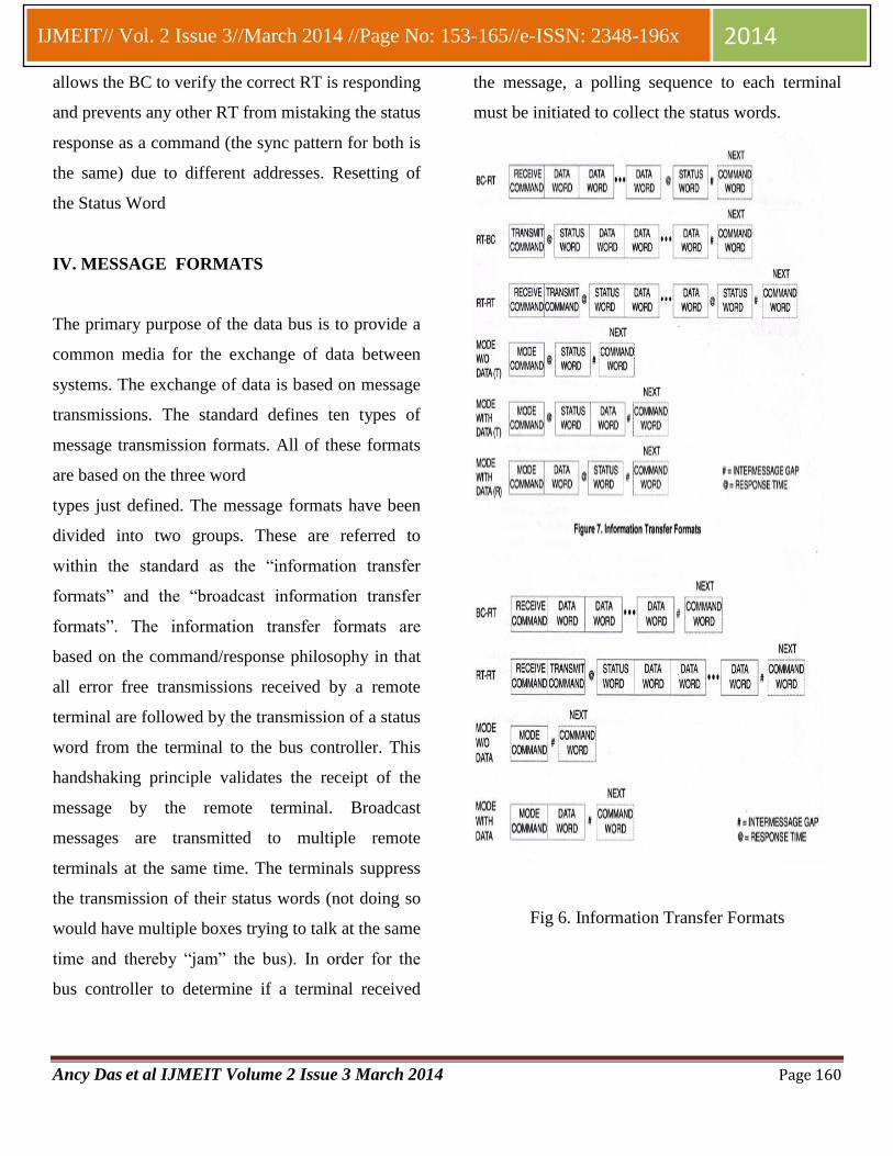
IV. MESSAGE FORMATS
The primary purpose of the data bus is to provide a
common media for the exchange of data between
systems. The exchange of data is based on message
transmissions. The standard defines ten types of
message transmission formats. All of these formats
are based on the three word
types just defined. The message formats have been
divided into two groups. These are referred to
within the standard as the “information transfer
formats” and the “broadcast information transfer
formats”. The information transfer formats are
based on the command/response philosophy in that
all error free transmissions received by a remote
terminal are followed by the transmission of a status
word from the terminal to the bus controller. This
handshaking principle validates the receipt of the
message by the remote terminal. Broadcast
messages are transmitted to multiple remote
terminals at the same time. The terminals suppress
the transmission of their status words (not doing so
would have multiple boxes trying to talk at the same
time and thereby “jam” the bus). In order for the
bus controller to determine if a terminal received
the message, a polling sequence to each terminal
must be initiated to collect the status words.
Fig 6. Information Transfer Formats

Ancy Das et al IJMEIT Volume 2 Issue 3 March 2014 Page 161
IJMEIT// Vol. 2 Issue 3//March 2014 //Page No: 153-165//e-ISSN: 2348-196x 2014
Bus Controller to Remote Terminal
The bus controller to remote terminal (BC-RT)
message is referred to as the receive command since
the remote terminal is going to receive data.
Remote Terminal to Bus Controller
The remote terminal to bus controller (RT-BC)
message is referred to as a transmit command. The
bus controller issues only a transmit command word
to the remote terminal.
Remote Terminal to Remote Terminal
The remote terminal to remote terminal (RT-RT)
command allows a terminal (the data source) to
transfer data directly to another terminal (the data
sink) without going through the bus controller.
Mode Command Formats
Three mode command formats are provided. This
allows for mode commands with no data words and
for the mode commands with one data word (either
transmitted or received). The status/data sequencing
is the same as the BC-RT or RT-BC messages
except that the data word count is either one or zero.
Broadcast Information Transfer Formats
The broadcast information transfer formats, as
shown in figure , is identical to the non-broadcast
formats described above with the following two
exceptions.
1. The bus controller issues commands to terminal
address 31 (11111B) that is reserved for this
function.
2. The remote terminals receiving the messages
(those that implement the broadcast option)
suppress the transmission of their status word.
Terminal Response Time
The standard states that a remote terminal, upon
validation of a transmit command word or a receive
message (command word and all data words) shall
transmit its status word to the bus controller. The
response time is the amount of time the terminal has
to transmit its status word
Inter-message Gap
The bus controller must provide for a minimum of
4.0 microseconds between messages. This time
frame is measured from the mid-crossing of the
parity bit of the last data word or the status word
and the mid-crossing of the sync field of the next
command word.
Superseding Commands
A remote terminal must always be capable of
receiving a new command. This may occur when
operating on a command on bus A, and after the
minimum inter-message gap, a new command
appears, or when operating on bus A, a new
command appears on bus B. This is referred to as a
Superseding command.
VI .SIMULATION RESULTS
Tool used: Modelsim 10.2b
ModelSim is an easy-to-use yet versatile
VHDL/(System)Verilog/SystemC simulator by
Mentor Graphics. It supports behavioral, register
transfer level, and gate-level modeling. ModelSim

Ancy Das et al IJMEIT Volume 2 Issue 3 March 2014 Page 162
IJMEIT// Vol. 2 Issue 3//March 2014 //Page No: 153-165//e-ISSN: 2348-196x 2014
supports all platforms used here at the Institute of
Digital and Computer Systems (i.e. Linux, Solaris
and Windows) and many others too. ModelSim is
an IDE for hardware design which provides
behavioral simulation of a number of languages,
i.e., Verilog, VHDL, and System C. HDL’s are
languages which are used to describe the
functionality of a piece of hardware as opposed to
the execution of sequential instructions like that in
a regular software application.
a. Simulation Result of message
transmission format: RT- BC
b. Simulation Result of message
transmission format : BC-RT
c. Simulation Result of message
transmission format: RT-RT

Ancy Das et al IJMEIT Volume 2 Issue 3 March 2014 Page 163
IJMEIT// Vol. 2 Issue 3//March 2014 //Page No: 153-165//e-ISSN: 2348-196x 2014
d. Simulation Result of message
transmission format: Mode W/O Data(T)
e. Simulation Result of message
transmission format: Mode with Data(T)
f. Simulation Result of message
transmission format: Mode with Data(R)
g. Simulation Result of message
transmission format : BC-RT(Broadcast)
Ancy Das et al IJMEIT Volume 2 Issue 3 March 2014 Page 164
IJMEIT// Vol. 2 Issue 3//March 2014 //Page No: 153-165//e-ISSN: 2348-196x 2014
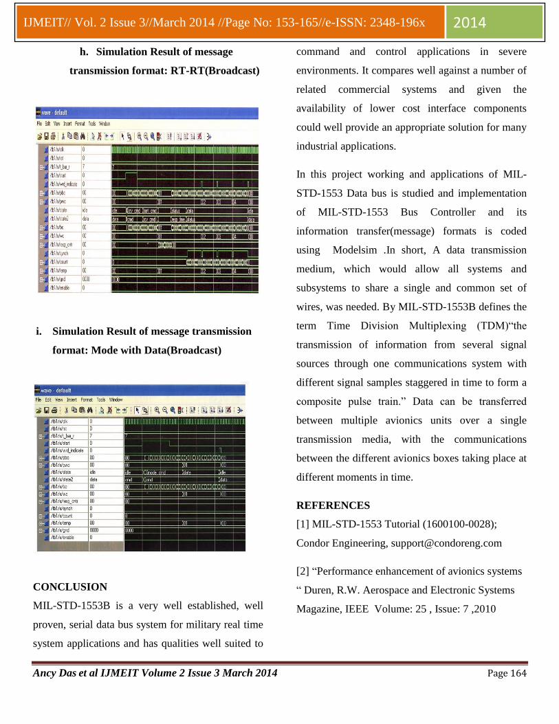
h. Simulation Result of message
transmission format: RT-RT(Broadcast)
i. Simulation Result of message transmission
format: Mode with Data(Broadcast)
CONCLUSION
MIL-STD-1553B is a very well established, well
proven, serial data bus system for military real time
system applications and has qualities well suited to
command and control applications in severe
environments. It compares well against a number of
related commercial systems and given the
availability of lower cost interface components
could well provide an appropriate solution for many
industrial applications.
In this project working and applications of MIL-
STD-1553 Data bus is studied and implementation
of MIL-STD-1553 Bus Controller and its
information transfer(message) formats is coded
using Modelsim .In short, A data transmission
medium, which would allow all systems and
subsystems to share a single and common set of
wires, was needed. By MIL-STD-1553B defines the
term Time Division Multiplexing (TDM)“the
transmission of information from several signal
sources through one communications system with
different signal samples staggered in time to form a
composite pulse train.” Data can be transferred
between multiple avionics units over a single
transmission media, with the communications
between the different avionics boxes taking place at
different moments in time.
REFERENCES
[1] MIL-STD-1553 Tutorial (1600100-0028);
Condor Engineering, [email protected]
[2] “Performance enhancement of avionics systems
“ Duren, R.W. Aerospace and Electronic Systems
Magazine, IEEE Volume: 25 , Issue: 7 ,2010
Ancy Das et al IJMEIT Volume 2 Issue 3 March 2014 Page 165
IJMEIT// Vol. 2 Issue 3//March 2014 //Page No: 153-165//e-ISSN: 2348-196x 2014
[3] “Using open networking standards overMIL-
STD-1553 networks”, Truitt, R.B. ; Sanchez,
E. ; Garis, M. Aerospace and Electronic Systems
Magazine, IEEE Volume: 20 , Issue: 3 .2005
[4] “A cost effective critical space systems design
approach” Abbott, L.W. ; Cox, G. ; Nguyen,
H. Aerospace and Electronic Systems Magazine,
IEEE Volume: 16 , Issue: 4 ,2001
[5] “Open systems avionics network to replaceMIL-
STD-1553”, Murdock, J.R. ; Koenig, J.R.
Aerospace and Electronic Systems Magazine, IEEE
Volume: 16 , Issue: 8
[6] “ Space systems general-purpose processor”,
Perschy, J.A. Aerospace and Electronic Systems
Magazine, IEEE Volume: 15 , Issue: 11 Publication
Year: 2000 , Page(s): 15 – 19
[7] www.actel.com
[8] Department of Defense , ”Interface standard for
digital time division command/response multiplex
data bus” .
[9] MIL-STD-Tutorial,www.aim-online.com.
[10] www.intersil.com
[11] Wikipedia.org