CPX terminal - Pneumatic & electric automation technology ... · Electronics manual CPX field bus...
134
Electronics manual CPX field bus node Type CPX-FB13 Field bus protocol PROFIBUS-DP as per EN 50170 CPX terminal Manual 526 428 en 0112NH [653 614]
Transcript of CPX terminal - Pneumatic & electric automation technology ... · Electronics manual CPX field bus...

Electronicsmanual
CPX field bus node
Type CPX-FB13
Field bus protocolPROFIBUS-DPas per EN 50170
CPX terminal
Manual526 428en 0112NH[653 614]


Contents and general instructions
IFesto P.BE-CPX-FB13-EN en 0112NH
Authors U. Reimann, U. Gräff. . . . . . . . . . . . . . . . . . . . . . . .
Editors H.-J. Drung, M. Holder. . . . . . . . . . . . . . . . . . . . . . . .
Original de. . . . . . . . . . . . . . . . . . . . . . . . . . . . . . . . . . . . . . .
Translation transline Deutschland. . . . . . . . . . . . . . . . . . . . .
Layout Festo AG & Co., Dept. KG-GD. . . . . . . . . . . . . . . . . . .
Type setting KI-DT. . . . . . . . . . . . . . . . . . . . . . . . . . . . . . . . . .
Edition en 0112NH. . . . . . . . . . . . . . . . . . . . . . . . . . . . . . . . .
Designation P.BE-CPX-FB13-EN. . . . . . . . . . . . . . . . . . . . . . .
Order no. 526 428. . . . . . . . . . . . . . . . . . . . . . . . . . . . . . . . .
E (Festo AG & Co., D-73726 Esslingen, Federal Republic ofGermany, 2002)Internet: http://www.festo.come-mail: [email protected]
The copying, distribution and utilization of this document aswell as the communication of its contents to others withoutexpressed authorization is prohibited. Offenders will be heldliable for the payment of damages. All rights are reserved, inparticular the right to carry out patent, utility model or orna-mental design registration.

Contents and general instructions
II Festo P.BE-CPX-FB13-EN en 0112NH

Contents and general instructions
IIIFesto P.BE-CPX-FB13-EN en 0112NH
Contents
Designated use VII. . . . . . . . . . . . . . . . . . . . . . . . . . . . . . . . . . . . . . . . . . . . . . . . . . . . . . . .Target group VIII. . . . . . . . . . . . . . . . . . . . . . . . . . . . . . . . . . . . . . . . . . . . . . . . . . . . . . . . . .Service VIII. . . . . . . . . . . . . . . . . . . . . . . . . . . . . . . . . . . . . . . . . . . . . . . . . . . . . . . . . . . . . . .Notes on the use of this manual VIII. . . . . . . . . . . . . . . . . . . . . . . . . . . . . . . . . . . . . . . . . . .Important user instructions IX. . . . . . . . . . . . . . . . . . . . . . . . . . . . . . . . . . . . . . . . . . . . . .
1. Installation 1-1. . . . . . . . . . . . . . . . . . . . . . . . . . . . . . . . . . . . . . . . . . . . . . . . . . .
1.1 General instructions on installation 1-4. . . . . . . . . . . . . . . . . . . . . . . . . . . . . . . .1.2 Settings of the DIL switches on the field bus node 1-8. . . . . . . . . . . . . . . . . . . .
1.2.1 Removing and fitting the cover over the DIL switches 1-8. . . . . . . . . . .1.2.2 Setting the DIL switches 1-9. . . . . . . . . . . . . . . . . . . . . . . . . . . . . . . . . .
1.3 Connecting the field bus 1-18. . . . . . . . . . . . . . . . . . . . . . . . . . . . . . . . . . . . . . . . .
1.3.1 Field bus cable 1-18. . . . . . . . . . . . . . . . . . . . . . . . . . . . . . . . . . . . . . . . . .1.3.2 Field bus baud rate and field bus length 1-19. . . . . . . . . . . . . . . . . . . . .1.3.3 Connecting the field bus 1-20. . . . . . . . . . . . . . . . . . . . . . . . . . . . . . . . . .
1.4 Bus termination with terminating resistors 1-23. . . . . . . . . . . . . . . . . . . . . . . . . .
1.5 Optical-fibre waveguide connection for PROFIBUS-DP 1-25. . . . . . . . . . . . . . . . .1.6 Pin assignment of power supply 1-26. . . . . . . . . . . . . . . . . . . . . . . . . . . . . . . . . . .
2. Commissioning 2-1. . . . . . . . . . . . . . . . . . . . . . . . . . . . . . . . . . . . . . . . . . . . . . . .
2.1 Configuration 2-4. . . . . . . . . . . . . . . . . . . . . . . . . . . . . . . . . . . . . . . . . . . . . . . . . .2.1.1 General information 2-4. . . . . . . . . . . . . . . . . . . . . . . . . . . . . . . . . . . . . .2.1.2 Preparing the CPX terminal for the configuration 2-5. . . . . . . . . . . . . .2.1.3 Device master file (GSD) and symbol files 2-11. . . . . . . . . . . . . . . . . . . .
2.1.4 Configuration with a Siemens master 2-12. . . . . . . . . . . . . . . . . . . . . . .2.2 Parametrizing 2-25. . . . . . . . . . . . . . . . . . . . . . . . . . . . . . . . . . . . . . . . . . . . . . . . . .
2.2.1 Parametrizing when the terminal is switched on 2-25. . . . . . . . . . . . . . .2.2.2 Parametrizing the CPX terminal with STEP 7 2-26. . . . . . . . . . . . . . . . . .
2.2.3 Parametrizing with the handheld 2-30. . . . . . . . . . . . . . . . . . . . . . . . . . .2.2.4 Application example of parametrizing 2-30. . . . . . . . . . . . . . . . . . . . . . .
2.3 Commissioning the CPX terminal in the system 2-31. . . . . . . . . . . . . . . . . . . . . . .2.3.1 Faultless commissioning, normal operating status 2-32. . . . . . . . . . . . .

Contents and general instructions
IV Festo P.BE-CPX-FB13-EN en 0112NH
3. Diagnosis 3-1. . . . . . . . . . . . . . . . . . . . . . . . . . . . . . . . . . . . . . . . . . . . . . . . . . . . .
3.1 Overview of diagnostic possibilities 3-4. . . . . . . . . . . . . . . . . . . . . . . . . . . . . . . .3.2 Diagnosis via LEDs 3-6. . . . . . . . . . . . . . . . . . . . . . . . . . . . . . . . . . . . . . . . . . . . . .
3.2.1 Fault displays of the bus fault/status LED BF 3-7. . . . . . . . . . . . . . . . .3.2.2 Error displays of the LEDs for system diagnosis PS, PL, SF, M 3-8. . . .
3.3 Diagnosis via status bits 3-11. . . . . . . . . . . . . . . . . . . . . . . . . . . . . . . . . . . . . . . . .3.4 Diagnosis via the I/O diagnostic interface 3-11. . . . . . . . . . . . . . . . . . . . . . . . . . .3.5 Diagnosis via PROFIBUS-DP 3-12. . . . . . . . . . . . . . . . . . . . . . . . . . . . . . . . . . . . . .
3.5.1 Diagnostic steps 3-13. . . . . . . . . . . . . . . . . . . . . . . . . . . . . . . . . . . . . . . .3.5.2 Overview of diagnostic bytes 3-14. . . . . . . . . . . . . . . . . . . . . . . . . . . . . .3.5.3 Details on standard diagnostic information 3-18. . . . . . . . . . . . . . . . . . .3.5.4 Module-related diagnosis 3-20. . . . . . . . . . . . . . . . . . . . . . . . . . . . . . . . .
3.5.5 Channel-related diagnosis 3-20. . . . . . . . . . . . . . . . . . . . . . . . . . . . . . . .3.6 Error treatment (Fail safe) 3-23. . . . . . . . . . . . . . . . . . . . . . . . . . . . . . . . . . . . . .
3.6.1 Siemens SIMATIC S5/S7 3-24. . . . . . . . . . . . . . . . . . . . . . . . . . . . . . . . . .3.7 Online diagnosis with STEP 7 3-27. . . . . . . . . . . . . . . . . . . . . . . . . . . . . . . . . . . . .
3.7.1 Read diagnostic buffer with STEP 7 (version 4.x, 5.1) 3-27. . . . . . . . . .3.7.2 Read device-specific diagnosis with STEP 7 (version 5.1) 3-29. . . . . . .
A. Technical appendix A-1. . . . . . . . . . . . . . . . . . . . . . . . . . . . . . . . . . . . . . . . . . . . .
A.1 Technical specifications of field bus node CPX-FB13 A-3. . . . . . . . . . . . . . . . . . .A.2 Operation with the general DP master A-4. . . . . . . . . . . . . . . . . . . . . . . . . . . . . .
A.2.1 Bus start A-4. . . . . . . . . . . . . . . . . . . . . . . . . . . . . . . . . . . . . . . . . . . . . . .A.2.2 Send parametriziung data A-5. . . . . . . . . . . . . . . . . . . . . . . . . . . . . . . .
A.2.3 Send configuration data A-7. . . . . . . . . . . . . . . . . . . . . . . . . . . . . . . . . .A.2.4 Error treatment A-10. . . . . . . . . . . . . . . . . . . . . . . . . . . . . . . . . . . . . . . . .A.2.5 Request diagnostic information A-10. . . . . . . . . . . . . . . . . . . . . . . . . . . .A.2.6 Start cyclic exchange of data A-10. . . . . . . . . . . . . . . . . . . . . . . . . . . . . .
A.2.7 Implemented functions and service access points (SAP) A-12. . . . . . . .A.2.8 Bus parameters/reaction times A-13. . . . . . . . . . . . . . . . . . . . . . . . . . . .A.2.9 Transmission times on the PROFIBUS-DP A-13. . . . . . . . . . . . . . . . . . . .
A.3 Access to the CPX terminal via DPV1 A-14. . . . . . . . . . . . . . . . . . . . . . . . . . . . . . .
A.3.1 Reading and writing data records A-14. . . . . . . . . . . . . . . . . . . . . . . . . .A.3.2 Data records A-17. . . . . . . . . . . . . . . . . . . . . . . . . . . . . . . . . . . . . . . . . . .
Contents and general instructions
VFesto P.BE-CPX-FB13-EN en 0112NH
B. Index B-1. . . . . . . . . . . . . . . . . . . . . . . . . . . . . . . . . . . . . . . . . . . . . . . . . . . . . . . . .
B.1 Index B-3. . . . . . . . . . . . . . . . . . . . . . . . . . . . . . . . . . . . . . . . . . . . . . . . . . . . . . . . .

Contents and general instructions
VI Festo P.BE-CPX-FB13-EN en 0112NH

Contents and general instructions
VIIFesto P.BE-CPX-FB13-EN en 0112NH
Designated use
The field bus node type CPX-FB13 described in this manualhas been designed exclusively for use as a slave on thePROFIBUS-DP.
The CPX terminal may only be used as follows:
in accordance with designated use
in its original state
without any modifications by the user
in faultless technical condition.
The maximum values specified for pressures, tempera-tures, electrical data, torques etc. must be observed.
Please comply with national and local safety laws and regula-tions.
Contents and general instructions
VIII Festo P.BE-CPX-FB13-EN en 0112NH
Target group
This manual is intended exclusively for technicians trained incontrol and automation technology, who have experience ininstalling, commissioning, programming and diagnosingslaves on the PROFIBUS-DP.
Service
Please consult your local Festo service centre if you have anytechnical problems.
Notes on the use of this manual
This manual contains specific information on installing, confi-guring, parametrizing, commissioning, programming anddiagnosing with the CPX field bus node for PROFIBUS-DP.
Further information on the PROFIBUS-DP can be found in:
The setting up guidelines for the PROFIBUS-DP
The manuals from the master manufacturer
Contents and general instructions
IXFesto P.BE-CPX-FB13-EN en 0112NH
Important user instructions
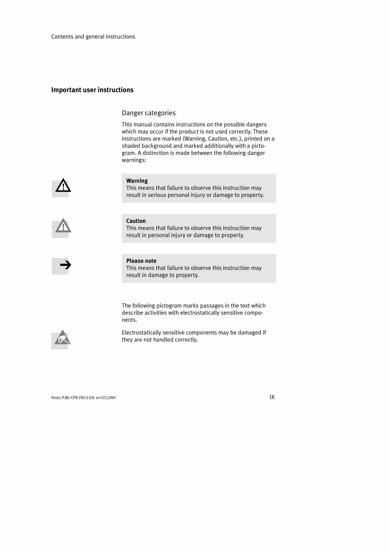
Danger categories
This manual contains instructions on the possible dangerswhich may occur if the product is not used correctly. Theseinstructions are marked (Warning, Caution, etc.), printed on ashaded background and marked additionally with a picto-gram. A distinction is made between the following dangerwarnings:
WarningThis means that failure to observe this instruction mayresult in serious personal injury or damage to property.
CautionThis means that failure to observe this instruction mayresult in personal injury or damage to property.
Please noteThis means that failure to observe this instruction mayresult in damage to property.
The following pictogram marks passages in the text whichdescribe activities with electrostatically sensitive compo-nents.
Electrostatically sensitive components may be damaged ifthey are not handled correctly.

Contents and general instructions
X Festo P.BE-CPX-FB13-EN en 0112NH
Marking special information
The following pictograms mark passages in the text contain-ing special information.
Pictograms
Information:Recommendations, tips and references to other sources ofinformation.
Accessories:Information on necessary or sensible accessories for theFesto product.
Environment:Information on environment-friendly use of Festo products.
Text markings
The bullet indicates activities which may be carried out inany order.
1. Figures denote activities which must be carried out in thenumerical order specified.
Hyphens indicate general activities.
Contents and general instructions
XIFesto P.BE-CPX-FB13-EN en 0112NH
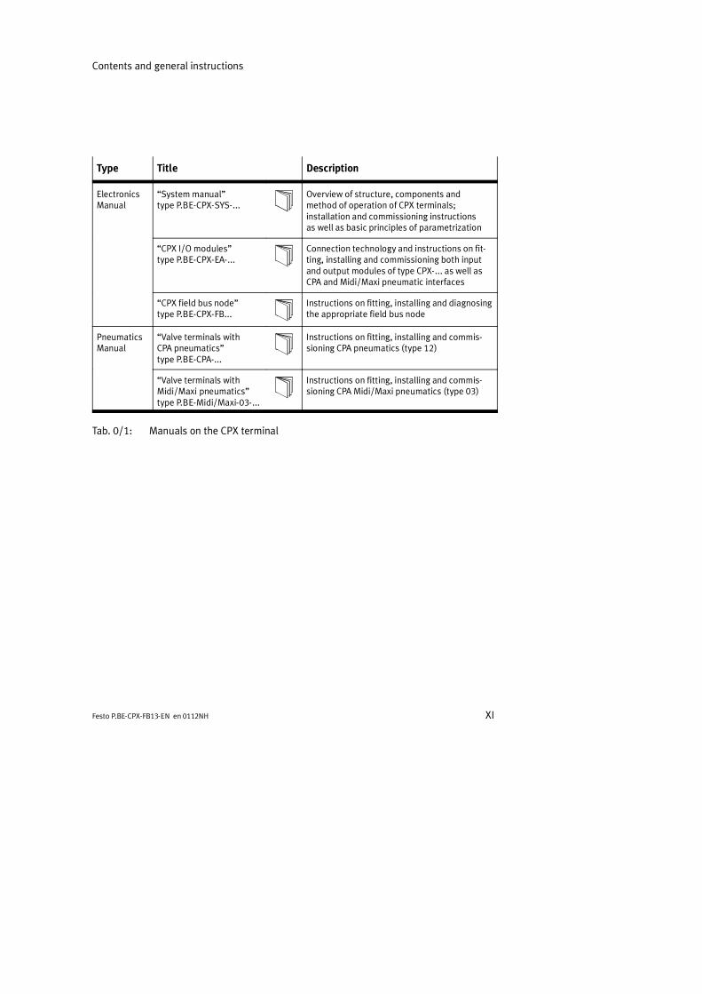
Type Title Description
ElectronicsManual
System manualtype P.BE-CPX-SYS-...
Overview of structure, components andmethod of operation of CPX terminals;installation and commissioning instructionsas well as basic principles of parametrization
CPX I/O modulestype P.BE-CPX-EA-...
Connection technology and instructions on fit-ting, installing and commissioning both inputand output modules of type CPX-... as well asCPA and Midi/Maxi pneumatic interfaces
CPX field bus nodetype P.BE-CPX-FB...
Instructions on fitting, installing and diagnosingthe appropriate field bus node
PneumaticsManual
Valve terminals withCPA pneumaticstype P.BE-CPA-...
Instructions on fitting, installing and commis-sioning CPA pneumatics (type 12)
Valve terminals withMidi/Maxi pneumaticstype P.BE-Midi/Maxi-03-...
Instructions on fitting, installing and commis-sioning CPA Midi/Maxi pneumatics (type 03)
Tab. 0/1: Manuals on the CPX terminal

Contents and general instructions
XII Festo P.BE-CPX-FB13-EN en 0112NH
The following product-specific terms and abbreviations areused in this manual:
Term/abbreviation Meaning
A0h Hexadecimal numbers are marked by a low-set h.
CP Compact performance
CP modules Common term for the various modules which can be incorporated in a CPXterminal.
CPX terminal Complete system consisting of CPX modules with or without pneumatics.
DIL switches Dual-in-line switches consist of several switch elements with which settingscan be made.
DPV1 PROFIBUS extension for acyclic access to system data during running time.
Field bus node Provides the connection to specific field buses. Transmits control signals tothe connected modules and monitors their ability to function.
Handheld Handheld programmer for commissioning and service purposes.
I Digital input
I/O modules Common term for the CPX modules which provide digital inputs andoutputs.
I/Os Digital inputs and outputs
O Digital output
Octet Number of address bytes assigned by the CPX terminal.
Output byte Output byte
PLC/IPC Programmable logic controller/industrial PC
Pneumatic interface The pneumatic interface is the interface between the modular electricperiphery and the pneumatics.
Tab. 0/2: Product-specific terms and abbreviations

Installation
1-1Festo P.BE-CPX-FB13-EN en 0112NH
Chapter 1
1. Installation
1-2 Festo P.BE-CPX-FB13-EN en 0112NH
Contents
1. Installation 1-1. . . . . . . . . . . . . . . . . . . . . . . . . . . . . . . . . . . . . . . . . . . . . . . . . . .
1.1 General instructions on installation 1-4. . . . . . . . . . . . . . . . . . . . . . . . . . . . . . . .1.2 Settings of the DIL switches on the field bus node 1-8. . . . . . . . . . . . . . . . . . . .
1.2.1 Removing and fitting the cover over the DIL switches 1-8. . . . . . . . . . .1.2.2 Setting the DIL switches 1-9. . . . . . . . . . . . . . . . . . . . . . . . . . . . . . . . . .
1.3 Connecting the field bus 1-18. . . . . . . . . . . . . . . . . . . . . . . . . . . . . . . . . . . . . . . . .1.3.1 Field bus cable 1-18. . . . . . . . . . . . . . . . . . . . . . . . . . . . . . . . . . . . . . . . . .1.3.2 Field bus baud rate and field bus length 1-19. . . . . . . . . . . . . . . . . . . . .1.3.3 Connecting the field bus 1-20. . . . . . . . . . . . . . . . . . . . . . . . . . . . . . . . . .
1.4 Bus termination with terminating resistors 1-23. . . . . . . . . . . . . . . . . . . . . . . . . .1.5 Optical-fibre waveguide connection for PROFIBUS-DP 1-25. . . . . . . . . . . . . . . . .1.6 Pin assignment of power supply 1-26. . . . . . . . . . . . . . . . . . . . . . . . . . . . . . . . . . .
1. Installation
1-3Festo P.BE-CPX-FB13-EN en 0112NH
Contents of this chapter In this chapter you will find information on
setting the CPX field bus node with DIL switches
the connection to the field bus
the pin assignment of the power supply.
Further information Information on fitting and installing the complete CPXterminal can be found in the CPX system manual(P.BE-CPX-SYS-..).
Information on installing the I/O modules and the pneumaticinterfaces can be found in the manual for the CPX pneumaticinterfaces and the CPX I/O modules (P.BE-CPX-EA-..).
Instructions on installing the pneumatics can be found in therelevant pneumatics manual.

1. Installation
1-4 Festo P.BE-CPX-FB13-EN en 0112NH
1.1 General instructions on installation
WarningBefore carrying out installation and maintenance work,switch off the following:
the compressed air supply
the operating voltage supply for the electronics/sensors
the load voltage supply for the outputs and valves.
You can thereby avoid:
uncontrolled movements of loose tubing
unexpected movements of the connected actuators
non-defined switching states of the electronic compo-nents.
CautionThe CPX field bus node contains electrostatically sensitivecomponents.
Do not therefore touch any contacts.
Observe the regulations for handling electrostaticallysensitive components.
You will then prevent the electronics from being damaged.
Information on fitting the CPX terminal can be found in theCPX system manual (P.BE-CPX-SYS-..).
1. Installation
1-5Festo P.BE-CPX-FB13-EN en 0112NH
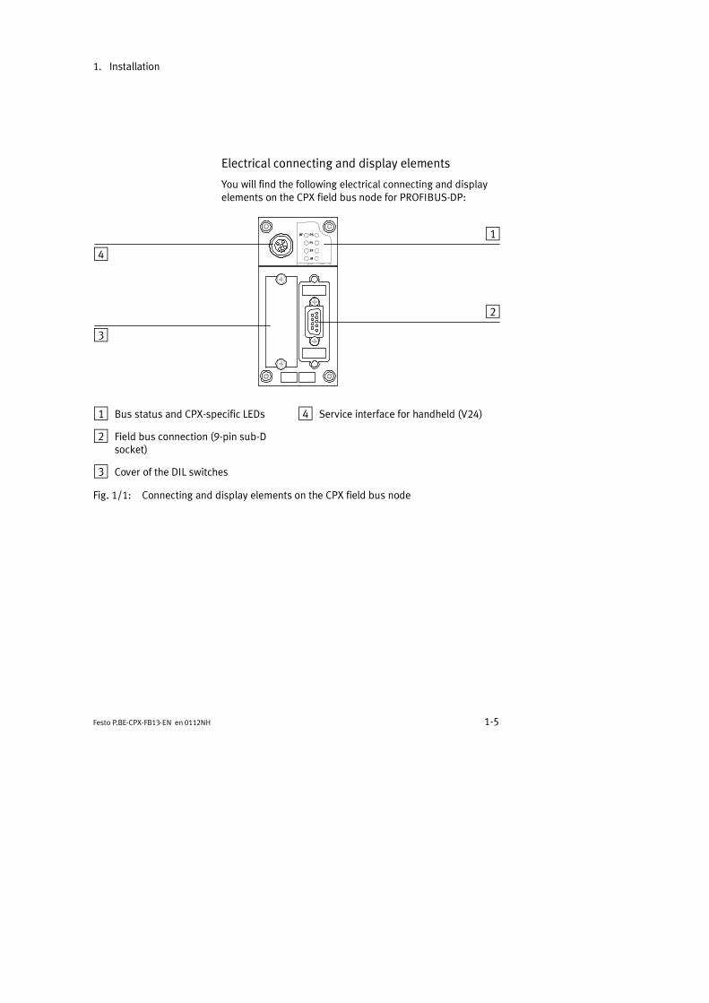
Electrical connecting and display elements
You will find the following electrical connecting and displayelements on the CPX field bus node for PROFIBUS-DP:
BF PS
PL
SF
M
1
2
3
4
1 Bus status and CPX-specific LEDs
2 Field bus connection (9-pin sub-Dsocket)
3 Cover of the DIL switches
4 Service interface for handheld (V24)
Fig. 1/1: Connecting and display elements on the CPX field bus node

1. Installation
1-6 Festo P.BE-CPX-FB13-EN en 0112NH
Fitting and removing
The field bus node is fitted in a manifold sub-base of the CPXterminal (see Fig. 1/2).
Removing Remove the field bus node as follows:
1. Loosen the 4 screws in the field bus node with a Torxscrewdriver size T10.
2. Pull the field bus node carefully and without tilting awayfrom the contact rails of the manifold sub-base.
1 Field bus nodeCPX-FB13
2 Manifoldsub-base
3 Contact rails
4 Screws
3
4
1
2
Fig. 1/2: Fitting/removing the field bus node

1. Installation
1-7Festo P.BE-CPX-FB13-EN en 0112NH
Fitting Fit the field bus node as follows:
1. Place the field bus node in the manifold sub-base. Makesure that the grooves with the contact terminals on thebottom of the field bus node lie above the contact rails.Then push the field bus node carefully and without tiltingas far as possible into the manifold sub-base.
2. Tighten the screws only by hand. Place the screws so thatthe self-cutting threads can be used.Tighten the screws with a Torx screwdriver size T10 withtorque 0.9...1.1 Nm.
1. Installation
1-8 Festo P.BE-CPX-FB13-EN en 0112NH
1.2 Settings of the DIL switches on the field bus node
In order to set the CPX field bus node you must first removethe cover over the DIL switches.
CautionThe CPX field bus node contains electrostatically sensitivecomponents.
Do not therefore touch any contacts.
Observe the regulations for handling electrostaticallysensitive components.
You will then prevent the electronics in the node from beingdamaged.
1.2.1 Removing and fitting the cover over the DIL switches
In order to set the CPX field bus node you must first removethe cover over the DIL switches.
Removing 1. Switch off the power supply.
2. Unscrew the two fastening screws in the switch cover.
3. Lift up the cover.
Fitting 1. Place the cover carefully on the node.
Please note Make sure that the seal is seated correctly.
2. Tighten the two fastening screws at first by hand and thenwith torque 0.5...0.8 Nm.

1. Installation
1-9Festo P.BE-CPX-FB13-EN en 0112NH
1.2.2 Setting the DIL switches
When you have removed the cover for the DIL switches, youwill see three DIL switches in the field bus node (see Fig. 1/3).
You can set the following parameters with the DIL switches:
the PROFIBUS address
the diagnostic mode.
Proceed as follows:
1. Switch off the power supply.
2. Remove the cover over the DIL switches (section 1.2.1).
3. Assign an unused station number to the CPX terminal.Set the desired station number (8-position DIL switch,elements 1...7).
4. Set the diagnostic mode (8-position DIL switch, element 8).
5. Fit the cover again (section 1.2.1).
1. Installation
1-10 Festo P.BE-CPX-FB13-EN en 0112NH
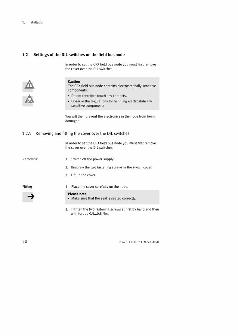
1 DIL switch 1:reserved
2 DIL switch 2:reserved
3 DIL switch 3:setting thediagnostic mode
4 DIL switch 3:setting thestation number
12
34
56
78
ON
1 2 1 2
ON ON
1 2
34
Fig. 1/3: DIL switch in the field bus node
Reserved DIL switches1 and2
Leave all switch elements of the 2-element DIL switches 1 and2 at OFF:
Reserved
Fig. 1/4: Setting of the 2-element DIL switch

1. Installation
1-11Festo P.BE-CPX-FB13-EN en 0112NH
Setting the diagnostic mode3
The following diagnosis can be activated/deactivated withswitch element 8 of the 8-element DIL switch 3:
PROFIBUS-DP: Device-related diagnosis active/inactive
If the device-related diagnosis is deactivated with switch el-ement 8, no device-related diagnostic information about theCPX terminal will be sent to the master system, e.g. shortcircuit at the outputs or undervoltage at the valves (see sec-tion 3.5).
Device-related diagnosisactive
Device-related diagnosisinactive
12
34
56
78
12
34
56
78
Fig. 1/5: Setting the diagnostic mode

1. Installation
1-12 Festo P.BE-CPX-FB13-EN en 0112NH
Setting the station number4
Please noteStation numbers may only be assigned once per field busmaster.
You can set the PROFIBUS address of the CPX terminal inbinary coded form with the 8-element DIL switch 3.
1 Setting thestation number(switch elements1...7)
12
34
56
78
1
Fig. 1/6: Setting the station number (8-element DIL switch)
The following station numbers are permitted:
Protocol Addressidentification
Permitted stationnumbers
PROFIBUS-DP PROFIBUS address 1; ...; 125
Recommendation:Assign the station numbers in ascending order. Assign thestation addresses to suit the machine structure of yoursystem.
1. Installation
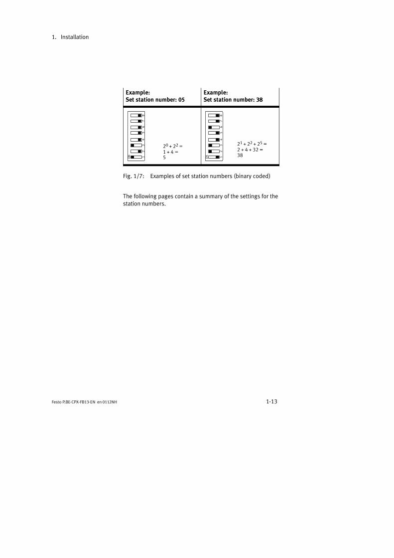
1-13Festo P.BE-CPX-FB13-EN en 0112NH
Example:Set station number: 05
Example:Set station number: 38
12
34
56
78
20 + 22 =1 + 4 =5 1
23
45
67
8
21 + 22 + 25 =2 + 4 + 32 =38
Fig. 1/7: Examples of set station numbers (binary coded)
The following pages contain a summary of the settings for thestation numbers.

1. Installation
1-14 Festo P.BE-CPX-FB13-EN en 0112NH
Sta-tionno.
1 2 3 4 5 6 7 8 Sta-tionno.
1 2 3 4 5 6 7 8
0 reserved 16OFF OFF OFF OFF
ON
OFF OFF
1 ON
OFF OFF OFF OFF OFF OFF17 ON
OFF OFF OFF
ON
OFF OFF
2OFF
ON
OFF OFF OFF OFF OFF18
OFF
ON
OFF OFF
ON
OFF OFF
3 ON ON
OFF OFF OFF OFF OFF19 ON ON
OFF OFF
ON
OFF OFF
4OFF OFF
ON
OFF OFF OFF OFF20
OFF OFF
ON
OFF
ON
OFF OFF
5 ON
OFF
ON
OFF OFF OFF OFF21 ON
OFF
ON
OFF
ON
OFF OFF
6OFF
ON ON
OFF OFF OFF OFF22
OFF
ON ON
OFF
ON
OFF OFF
7 ON ON ON
OFF OFF OFF OFF23 ON ON ON
OFF
ON
OFF OFF
8OFF OFF OFF
ON
OFF OFF OFF24
OFF OFF OFF
ON ON
OFF OFF
9 ON
OFF OFF
ON
OFF OFF OFF25 ON
OFF OFF
ON ON
OFF OFF
10OFF
ON
OFF
ON
OFF OFF OFF26
OFF
ON
OFF
ON ON
OFF OFF
11 ON ON
OFF
ON
OFF OFF OFF27 ON ON
OFF
ON ON
OFF OFF
12OFF OFF
ON ON
OFF OFF OFF28
OFF OFF
ON ON ON
OFF OFF
13 ON
OFF
ON ON
OFF OFF OFF29 ON
OFF
ON ON ON
OFF OFF
14OFF
ON ON ON
OFF OFF OFF30
OFF
ON ON ON ON
OFF OFF
15 ON ON ON ON
OFF OFF OFF31 ON ON ON ON ON
OFF OFF
Tab. 1/1: Settings of station numbers 1...31: Position of the DIL switch elements
1. Installation
1-15Festo P.BE-CPX-FB13-EN en 0112NH
Sta-tionno.
1 2 3 4 5 6 7 8 Sta-tionno.
1 2 3 4 5 6 7 8
32OFF OFF OFF OFF OFF
ON
OFF48
OFF OFF OFF OFF
ON ON
OFF
33 ON
OFF OFF OFF OFF
ON
OFF49 ON
OFF OFF OFF
ON ON
OFF
34OFF
ON
OFF OFF OFF
ON
OFF50
OFF
ON
OFF OFF
ON ON
OFF
35 ON ON
OFF OFF OFF
ON
OFF51 ON ON
OFF OFF
ON ON
OFF
36OFF OFF
ON
OFF OFF
ON
OFF52
OFF OFF
ON
OFF
ON ON
OFF
37 ON
OFF
ON
OFF OFF
ON
OFF53 ON
OFF
ON
OFF
ON ON
OFF
38OFF
ON ON
OFF OFF
ON
OFF54
OFF
ON ON
OFF
ON ON
OFF
39 ON ON ON
OFF OFF
ON
OFF55 ON ON ON
OFF
ON ON
OFF
40OFF OFF OFF
ON
OFF
ON
OFF56
OFF OFF OFF
ON ON ON
OFF
41 ON
OFF OFF
ON
OFF
ON
OFF57 ON
OFF OFF
ON ON ON
OFF
42OFF
ON
OFF
ON
OFF
ON
OFF58
OFF
ON
OFF
ON ON ON
OFF
43 ON ON
OFF
ON
OFF
ON
OFF59 ON ON
OFF
ON ON ON
OFF
44OFF OFF
ON ON
OFF
ON
OFF60
OFF OFF
ON ON ON ON
OFF
45 ON
OFF
ON ON
OFF
ON
OFF61 ON
OFF
ON ON ON ON
OFF
46OFF
ON ON ON
OFF
ON
OFF62
OFF
ON ON ON ON ON
OFF
47 ON ON ON ON
OFF
ON
OFF63 ON ON ON ON ON ON
OFF
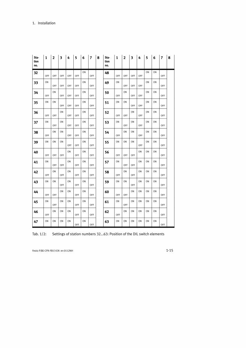
Tab. 1/2: Settings of station numbers 32...63: Position of the DIL switch elements
1. Installation
1-16 Festo P.BE-CPX-FB13-EN en 0112NH
Sta-tionno.
1 2 3 4 5 6 7 8 Sta-tionno.
1 2 3 4 5 6 7 8
64OFF OFF OFF OFF OFF OFF
ON 80OFF OFF OFF OFF
ON
OFF
ON
65 ON
OFF OFF OFF OFF OFF
ON 81 ON
OFF OFF OFF
ON
OFF
ON
66OFF
ON
OFF OFF OFF OFF
ON 82OFF
ON
OFF OFF
ON
OFF
ON
67 ON ON
OFF OFF OFF OFF
ON 83 ON ON
OFF OFF
ON
OFF
ON
68OFF OFF
ON
OFF OFF OFF
ON 84OFF OFF
ON
OFF
ON
OFF
ON
69 ON
OFF
ON
OFF OFF OFF
ON 85 ON
OFF
ON
OFF
ON
OFF
ON
70OFF
ON ON
OFF OFF OFF
ON 86OFF
ON ON
OFF
ON
OFF
ON
71 ON ON ON
OFF OFF OFF
ON 87 ON ON ON
OFF
ON
OFF
ON
72OFF OFF OFF
ON
OFF OFF
ON 88OFF OFF OFF
ON ON
OFF
ON
73 ON
OFF OFF
ON
OFF OFF
ON 89 ON
OFF OFF
ON ON
OFF
ON
74OFF
ON
OFF
ON
OFF OFF
ON 90OFF
ON
OFF
ON ON
OFF
ON
75 ON ON
OFF
ON
OFF OFF
ON 91 ON ON
OFF
ON ON
OFF
ON
76OFF OFF
ON ON
OFF OFF
ON 92OFF OFF
ON ON ON
OFF
ON
77 ON
OFF
ON ON
OFF OFF
ON 93 ON
OFF
ON ON ON
OFF
ON
78OFF
ON ON ON
OFF OFF
ON 94OFF
ON ON ON ON
OFF
ON
79 ON ON ON ON
OFF OFF
ON 95 ON ON ON ON ON
OFF
ON
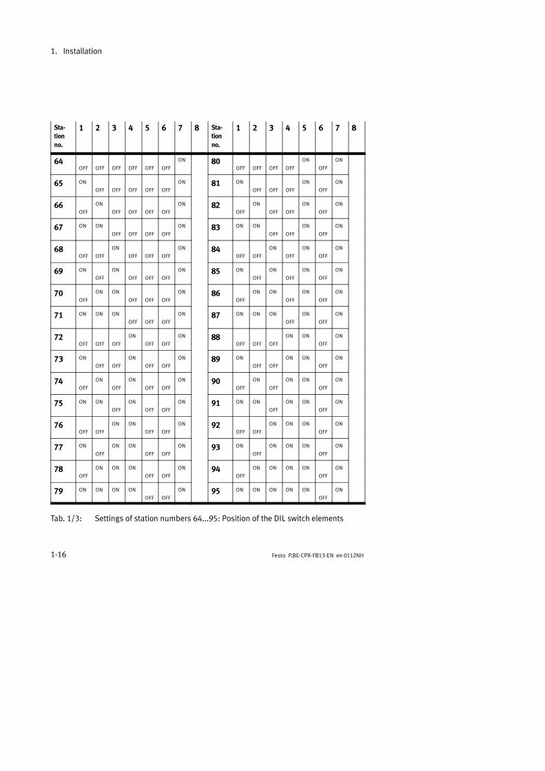
Tab. 1/3: Settings of station numbers 64...95: Position of the DIL switch elements

1. Installation
1-17Festo P.BE-CPX-FB13-EN en 0112NH
Sta-tionno.
1 2 3 4 5 6 7 8 Sta-tionno.
1 2 3 4 5 6 7 8
96OFF OFF OFF OFF OFF
ON ON 111 ON ON ON ON
OFF
ON ON
97 ON
OFF OFF OFF OFF
ON ON 112OFF OFF OFF OFF
ON ON ON
98OFF
ON
OFF OFF OFF
ON ON 113 ON
OFF OFF OFF
ON ON ON
99 ON ON
OFF OFF OFF
ON ON 114OFF
ON
OFF OFF
ON ON ON
100OFF OFF
ON
OFF OFF
ON ON 115 ON ON
OFF OFF
ON ON ON
101 ON
OFF
ON
OFF OFF
ON ON 116OFF OFF
ON
OFF
ON ON ON
102OFF
ON ON
OFF OFF
ON ON 117 ON
OFF
ON
OFF
ON ON ON
103 ON ON ON
OFF OFF
ON ON 118OFF
ON ON
OFF
ON ON ON
104OFF OFF OFF
ON
OFF
ON ON 119 ON ON ON
OFF
ON ON ON
105 ON
OFF OFF
ON
OFF
ON ON 120OFF OFF OFF
ON ON ON ON
106OFF
ON
OFF
ON
OFF
ON ON 121 ON
OFF OFF
ON ON ON ON
107 ON ON
OFF
ON
OFF
ON ON 122OFF
ON
OFF
ON ON ON ON
108OFF OFF
ON ON
OFF
ON ON 123 ON ON ON
OFF
ON ON ON
109 ON
OFF
ON ON
OFF
ON ON 124OFF OFF
ON ON ON ON ON
110OFF
ON ON ON
OFF
ON ON 125 ON
OFF
ON ON ON ON ON
Tab. 1/4: Settings of station numbers 96...125: Position of the DIL switch elements
1. Installation
1-18 Festo P.BE-CPX-FB13-EN en 0112NH
1.3 Connecting the field bus
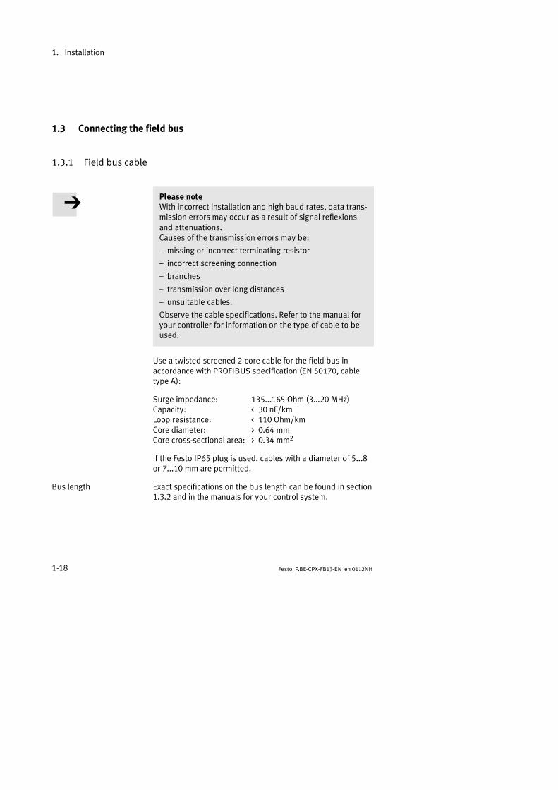
1.3.1 Field bus cable
Please noteWith incorrect installation and high baud rates, data trans-mission errors may occur as a result of signal reflexionsand attenuations.Causes of the transmission errors may be:
missing or incorrect terminating resistor
incorrect screening connection
branches
transmission over long distances
unsuitable cables.
Observe the cable specifications. Refer to the manual foryour controller for information on the type of cable to beused.
Use a twisted screened 2-core cable for the field bus inaccordance with PROFIBUS specification (EN 50170, cabletype A):
Surge impedance: 135...165 Ohm (3...20 MHz)Capacity: < 30 nF/kmLoop resistance: < 110 Ohm/kmCore diameter: > 0.64 mmCore cross-sectional area: > 0.34 mm2
If the Festo IP65 plug is used, cables with a diameter of 5...8or 7...10 mm are permitted.
Bus length Exact specifications on the bus length can be found in section1.3.2 and in the manuals for your control system.
1. Installation
1-19Festo P.BE-CPX-FB13-EN en 0112NH
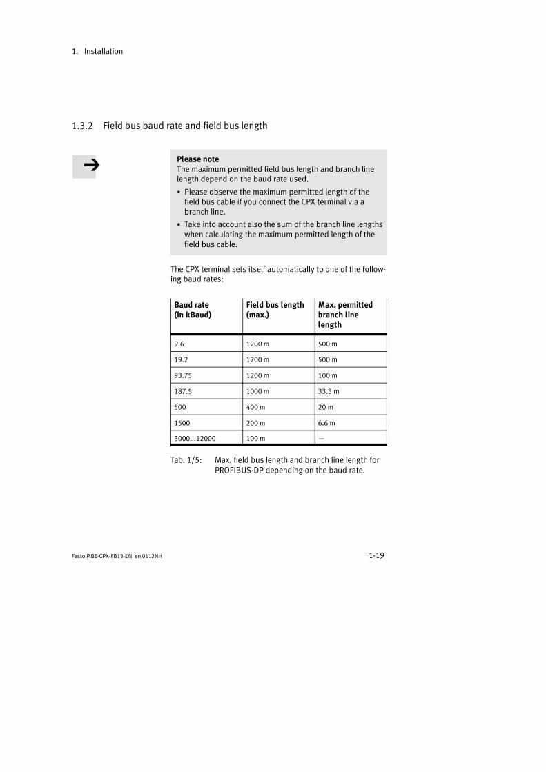
1.3.2 Field bus baud rate and field bus length
Please noteThe maximum permitted field bus length and branch linelength depend on the baud rate used.
Please observe the maximum permitted length of thefield bus cable if you connect the CPX terminal via abranch line.
Take into account also the sum of the branch line lengthswhen calculating the maximum permitted length of thefield bus cable.
The CPX terminal sets itself automatically to one of the follow-ing baud rates:
Baud rate(in kBaud)
Field bus length(max.)
Max. permittedbranch linelength
9.6 1200 m 500 m
19.2 1200 m 500 m
93.75 1200 m 100 m
187.5 1000 m 33.3 m
500 400 m 20 m
1500 200 m 6.6 m
3000...12000 100 m
Tab. 1/5: Max. field bus length and branch line length forPROFIBUS-DP depending on the baud rate.
1. Installation
1-20 Festo P.BE-CPX-FB13-EN en 0112NH
1.3.3 Connecting the field bus
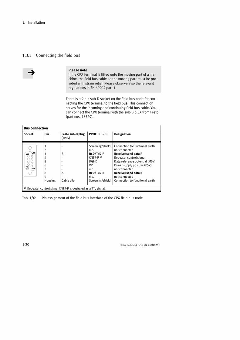
Please noteIf the CPX terminal is fitted onto the moving part of a ma-chine, the field bus cable on the moving part must be pro-vided with strain relief. Please observe also the relevantregulations in EN 60204 part 1.
There is a 9-pin sub-D socket on the field bus node for con-necting the CPX terminal to the field bus. This connectionserves for the incoming and continuing field bus cable. Youcan connect the CPX terminal with the sub-D plug from Festo(part nos. 18529).
Bus connection
Socket Pin Festo sub-D plug(IP65)
PROFIBUS-DP Designation
123456789Housing
--B----A-Cable clip
Screening/shieldn.c.RxD/TxD-PCNTR-P 1)
DGNDVPn.c.RxD/TxD-Nn.c.Screening/shield
Connection to functional earthnot connectedReceive/send data PRepeater control signalData reference potential (M5V)Power supply positive (P5V)not connectedReceive/send data Nnot connectedConnection to functional earth
1) Repeater control signal CNTR-P is designed as a TTL signal.
Tab. 1/6: Pin assignment of the field bus interface of the CPX field bus node

1. Installation
1-21Festo P.BE-CPX-FB13-EN en 0112NH
Please notePlease note that only the Festo plug complies with protec-tion class IP65.
Before connecting the sub-D plugs of other manufacturers:
replace the two flat screws by bolts(type UNC 4-40/M3x6).
Sub-D plugs from Festo
A floating screening connection is intended with the sub-Dplug from Festo:
Clamp the screening/shield for the field bus cable underthe cable clip of the Festo plug.
The diagram below shows the pin assignment in the Festosub-D plug.
1 Screeningconnection,cable clip
2 Only connectedcapacitively
3 CPX field busnode (smallerthan actual size)
4 Pin assignmentin the plugA: RxD/TxD-NB: RxD/TxD-P
ON
1
2
A B
nota
ssigned
nota
ssigned
3
4
BF PSPLSFM
Fig. 1/8: Sub-D plugs from Festo: Pin assignment and screening connection
1. Installation
1-22 Festo P.BE-CPX-FB13-EN en 0112NH
Please noteThe cable clip in the sub-D plug from Festo is connectedinternally only capacitively with the metallic outer ring ofthe plug. This is to prevent equalizing currents flowingthrough the screening of the field bus cable (Fig. 1/8).

1. Installation
1-23Festo P.BE-CPX-FB13-EN en 0112NH
1.4 Bus termination with terminating resistors
Please noteIf the CPX terminal is at the beginning or end of the fieldbus system, a bus termination will be required.
Fit a bus termination to both ends of the bus segment.
Recommendation:Use the sub-D plug from Festo (part no. 18529) for the bustermination. A suitable resistor network is incorporated in thehousing of this plug. The bus termination must be switchedmanually with slide switches.
1 Blanking plug
2 Slide switch
ON ONA B
A B switched onnotswitched on
1
2
Bus termination
Fig. 1/9: Switch for bus termination in the Festo sub-D plug

1. Installation
1-24 Festo P.BE-CPX-FB13-EN en 0112NH
1 Switch in theFesto sub-D plug
2 Pin 6: Powersupply
3 Pin 5: Data refer-ence potential Receive/send data P
(data cable B)
Receive/send data N(data cable A)
390 Ω
390 Ω
220 Ω
1
1
2
3
Pin 6
Pin 5
Pin 3
Pin 8
120 nH
120 nH
Fig. 1/10: Circuit diagram for bus connection network for cable type A as per EN 50170

1. Installation
1-25Festo P.BE-CPX-FB13-EN en 0112NH
1.5 Optical-fibre waveguide connection for PROFIBUS-DP
Optical-fibre waveguide technology is to be recommendedwhen transmission is affected by heavy interference, as wellas for extending the transmission range when high baud ratesare used.
This also offers the following advantages:
high EMC compatibility, ESD protection due to the opticaltransmission of signals
protection against lightning
potential isolation of the individual DP slaves.
The PROFIBUS-DP interface of the CPX terminal has beendesigned in accordance with specification EN 50170 Volume2, and can therefore be used for controlling network compo-nents for optical-fibre waveguides.
Example of optical-fibre waveguide network components:
Siemens Optical Link Module (OLM) for PROFIBUS plus
Siemens Optical Link Plug (OLM) for PROFIBUS (IP20)
Harting Han-InduNet® Media converter IP65 in combina-tion with adapter cable for Festo valve terminals (opticaldata transmission in DESINA installation concept).
1. Installation
1-26 Festo P.BE-CPX-FB13-EN en 0112NH
1.6 Pin assignment of power supply
WarningUse only power units which guarantee reliable isolation ofthe operating voltages as per IEC 742/EN 60742/VDE 0551with at least 4 kV isolation resistance (Protected Extra LowVoltage PELV). Switch power packs are permitted, provid-ing they guarantee reliable isolation in accordance withEN 60950/VDE 0805.
By the use of PELV power units, protection against electricshock (protection against direct and indirect contact) is guar-anteed in accordance with EN 60204-1/IEC 204. Safety trans-formers with the adjacent symbol must be used for supplyingPELV networks. The CPX terminal must be earthed to ensurethat it functions correctly (e.g. EMC).
The current consumption of a CPX terminal depends on thenumber and type of integrated modules and components.
Read the information on power supply as well as on theearthing measures to be carried out in the CPX systemmanual.

1. Installation
1-27Festo P.BE-CPX-FB13-EN en 0112NH
System supply andadditional supply
The load and operating voltages are supplied to the CPXterminal via the manifold sub-bases with system supply andadditional supply type CPX-GE-EV-S or CPX-GE-EV-.. .
1 Pin assignment
1: Operating voltagefor electronics/sensors (VEL/SEN)
2: Load voltage forvalves and out-puts (VVAL/VOUT)
3: 0 V
4: Earth/groundconnection
1
2
3
4
1
Fig. 1/11: Pin assignment of the system supply (manifold sub-base type CPX-GE-EV-S)
1 Pin assignment
1: Not connected
2: Load voltage
3: 0 V
4: Earth/groundconnection
1
2
3
4
1
Fig. 1/12: Pin assignment of the additional supply (manifold sub-base type CPX-GE-EV-..)

1. Installation
1-28 Festo P.BE-CPX-FB13-EN en 0112NH

Commissioning
2-1Festo P.BE-CPX-FB13-EN en 0112NH
Chapter 2
2. Commissioning
2-2 Festo P.BE-CPX-FB13-EN en 0112NH
Contents
2. Commissioning 2-1. . . . . . . . . . . . . . . . . . . . . . . . . . . . . . . . . . . . . . . . . . . . . . . .
2.1 Configuration 2-4. . . . . . . . . . . . . . . . . . . . . . . . . . . . . . . . . . . . . . . . . . . . . . . . . .2.1.1 General information 2-4. . . . . . . . . . . . . . . . . . . . . . . . . . . . . . . . . . . . . .2.1.2 Preparing the CPX terminal for the configuration 2-5. . . . . . . . . . . . . .2.1.3 Device master file (GSD) and symbol files 2-11. . . . . . . . . . . . . . . . . . . .
2.1.4 Configuration with a Siemens master 2-12. . . . . . . . . . . . . . . . . . . . . . .2.2 Parametrizing 2-25. . . . . . . . . . . . . . . . . . . . . . . . . . . . . . . . . . . . . . . . . . . . . . . . . .
2.2.1 Parametrizing when the terminal is switched on 2-25. . . . . . . . . . . . . . .2.2.2 Parametrizing the CPX terminal with STEP 7 2-26. . . . . . . . . . . . . . . . . .
2.2.3 Parametrizing with the handheld 2-30. . . . . . . . . . . . . . . . . . . . . . . . . . .2.2.4 Application example of parametrizing 2-30. . . . . . . . . . . . . . . . . . . . . . .
2.3 Commissioning the CPX terminal in the system 2-31. . . . . . . . . . . . . . . . . . . . . . .2.3.1 Faultless commissioning, normal operating status 2-32. . . . . . . . . . . . .

2. Commissioning
2-3Festo P.BE-CPX-FB13-EN en 0112NH
Contents of this chapter In this chapter you will find information on commissioning theCPX terminal on the PROFIBUS-DP.
CPX terminal configuration and addressing.The bus configuration is explained using as an examplethe software COM PROFIBUS 5.x and STEP 7 V5.1 SP2.
The reaction of the CPX terminal can be adapted to indi-vidual requirements by parametrizing. This permits e.g.the setting of debouncing times, signal extensions or thereaction to faults.
Further information Before commissioning the CPX terminal, you must install itcorrectly. Information on this can be found in Chapter 1. Com-missioning with a general DP master can be found in Appen-dix A.
General information on commissioning the CPX terminal aswell as a detailed description of the individual parameterscan be found in the CPX system manual (P.BE-CPX-SYS-..).
Information on commissioning the pneumatic interfaces andI/O modules can be found in the manual for the CPX I/O mod-ules (P.BE-CPX-EA-..).
Instructions on commissioning the pneumatics can be foundin the relevant pneumatics manual.
2. Commissioning
2-4 Festo P.BE-CPX-FB13-EN en 0112NH
2.1 Configuration
2.1.1 General information
Control commands
The control commands FREEZE, SYNC and CLEAR_DATA aresupported by the CPX terminal in accordance with EN 50170(DIN 19245). The method of accessing these commands de-pends on the controller used. Please refer here to the docu-mentation for your field bus module.Information on DPV1 commands can be found in section A.3in Appendix A.
CautionIn the following cases, the FREEZE or SYNC mode will bereset automatically:
when the CPX terminal is switched on or off
when the field bus module is stopped.
The FREEZE mode will also be reset automatically in thefollowing case:
when the bus connection to the CPX terminal is inter-rupted (response monitoring active).
FREEZE
With this function all the inputs of the CPX terminal can befrozen. The CPX terminal then sends a constant input imageof all the inputs to the master. The following FREEZE com-mand causes the input image to be updated. The updatedinput image is then sent constantly to the master.Return to normal operation: UNFREEZE command.

2. Commissioning
2-5Festo P.BE-CPX-FB13-EN en 0112NH
SYNC
With this function all the outputs of the CPX terminal can befrozen. The CPX terminal then no longer reacts to modifica-tions of the output image in the master. The following SYNCcommand causes the output image of the master to be up-dated and accepted.Return to normal operation: UNSYNC command.
CLEAR_DATA
With this function all the outputs of the CPX terminal will bereset.
2.1.2 Preparing the CPX terminal for the configuration
Addressing the CPX terminal
The CPX terminal has an address range of up to 64 bytesinputs and 64 bytes outputs:Max_Data_Len = 128 (80H)
Inputs
Counting is module-orientated, irrespective of the posi-tion of the field bus node.
Counting from left to right.
Depending on the configuration, the field bus node canoccupy status information as logical inputs.
Outputs
Counting is module-orientated, irrespective of the posi-tion of the field bus node.
Counting from left to right.
2. Commissioning
2-6 Festo P.BE-CPX-FB13-EN en 0112NH
Electric modules
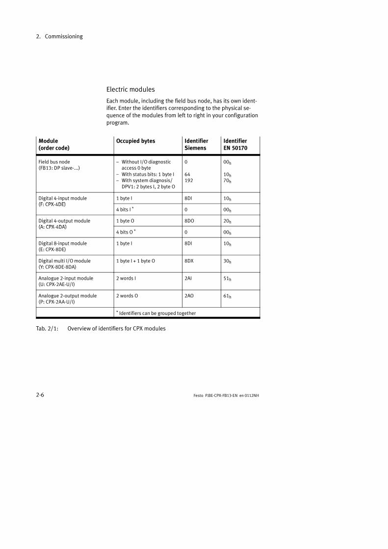
Each module, including the field bus node, has its own ident-ifier. Enter the identifiers corresponding to the physical se-quence of the modules from left to right in your configurationprogram.
Module(order code)
Occupied bytes IdentifierSiemens
IdentifierEN 50170
Field bus node(FB13: DP slave-...)
Without I/O diagnosticaccess 0 byte
With status bits: 1 byte I With system diagnosis/
DPV1: 2 bytes I, 2 byte O
0
64192
00h
10h70h
Digital 4-input module(F CPX 4DE)
1 byte I 8DI 10h(F: CPX-4DE)
4 bits I * 0 00h
Digital 4-output module(A CPX 4DA)
1 byte O 8DO 20h(A: CPX-4DA)
4 bits O * 0 00h
Digital 8-input module(E: CPX-8DE)
1 byte I 8DI 10h
Digital multi I/O module(Y: CPX-8DE-8DA)
1 byte I + 1 byte O 8DX 30h
Analogue 2-input module(U: CPX-2AE-U/I)
2 words I 2AI 51h
Analogue 2-output module(P: CPX-2AA-U/I)
2 words O 2AO 61h
* Identifiers can be grouped together
Tab. 2/1: Overview of identifiers for CPX modules

2. Commissioning
2-7Festo P.BE-CPX-FB13-EN en 0112NH
Special identifier format and groupable identifiers
Configuration is made PROFIBUS-specific byte-by-byte. Bymeans of a special identifier format you can group somemodules within a byte together. The data volume will then bereduced.
01234567
2. Module 1. Module
(e.g. 2 x 4DO)
Fig. 2/1: 2 modules grouped together in an identifier byte
You can only group together modules of the same type:
input modules
output modules
Any other module types may be placed between the groupedmodules. Further information can be found in the configur-ation example below.
2. Commissioning
2-8 Festo P.BE-CPX-FB13-EN en 0112NH
Valves
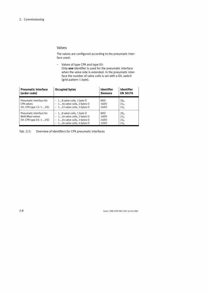
The valves are configured according to the pneumatic inter-face used:
Valves of type CPA and type 03:Only one identifier is used for the pneumatic interfacewhen the valve side is extended. In the pneumatic inter-face the number of valve coils is set with a DIL switch(grid pattern 1 byte).
Pneumatic interface(order code)
Occupied bytes IdentifierSiemens
IdentifierEN 50170
Pneumatic interface forCPA valves(VI: CPX type 12: 1-...VS)
1...8 valve coils, 1 byte O 1...16 valve coils, 2 bytes O 1...22 valve coils, 3 bytes O
8DO16DO24DO
20h21h22h
Pneumatic interface forMidi/Maxi valves(VI: CPX type 03: 1-...VS)
1...8 valve coils, 1 byte O 1...16 valve coils, 2 bytes O 1...24 valve coils, 3 bytes O 1...26 valve coils, 4 bytes O
8DO16DO24DO32DO
20h21h22h23h
Tab. 2/2: Overview of identifiers for CPX pneumatic interfaces

2. Commissioning
2-9Festo P.BE-CPX-FB13-EN en 0112NH
Configuration example
The following CPX terminal is used throughout this manual asthe configuration example:
0 1 2 3 4
1 2 3 4 5 6 7 8
5 6
8DI 8DI 4DO 8DI 4DO
Module no.:
8DO
OPE
N
12345678
1 Field bus node CPX-FB13
2 8-input module
3 8-input module
4 4-output module
5 Multi I/O module
6 4-output module
7 Pneumatic interface (set with DILswitch to 1...16 valve coils)
8 Valves/CPA pneumatics
Fig. 2/2: Example of a CPX terminal with electric modules with M12 connections and CPApneumatics
Configure the CPX terminal module-by-module from left toright. The following table shows the configuration of thesample terminal:

2. Commissioning
2-10 Festo P.BE-CPX-FB13-EN en 0112NH
Mod.no.
Module DP identifierSiemens
DP identifierEN 50170
Explanation
0 Field bus node(FB13: DP slave systemstatus)
64d 70h Configured with status bits
1 Digital 8-input module(E: CPX-8DE)
8DI 10h Identifier byte used com-pletely
2 Digital 8-input module(E: CPX-8DE)
8DI 10h Identifier byte used com-pletely
3 Digital 4-output module(A: CPX-4DA 2x)
8DO 20h Only the first 4 bits of theidentifier byte are used.1)
4 Digital multi I/O module(Y: CPX-8DE-8DA)
8DX 30h Identifier byte used com-pletely
5 Digital 4-output module(* A: CPX-4DA)
0d 00h The remaining 4 bits of theidentifier byte of module no. 3are used.
6 CPA pneumatic inter-face, set with DIL switchto 1...16 valve coils.(VI: CPX-GP-CPA-...)
16DO 21h The pneumatic interface mustbe configured correctlyaccording to the connectedpneumatics.
* Identifier grouped together1) If no module with groupable identifier is used on the subsequent locations, 8 bits will be
occupied (4 used).
Tab. 2/3: Configuration of the sample terminal from Fig. 2/2
The identifier bytes from locations 3 and 5 are groupedtogether. The identifier with the star symbol is used in loca-tion 5.
Please noteMake sure that the modules are correctly groupedtogether. This is not checked by the planning softwareCOM PROFIBUS or STEP 7.

2. Commissioning
2-11Festo P.BE-CPX-FB13-EN en 0112NH
2.1.3 Device master file (GSD) and symbol files
In order to configure the CPX terminal with a PC/programmeryou will require the appropriate GSD file. In addition to slave-typical entries (Ident. number, Revision, etc.), the devicemaster file (GSD) also contains a selection of identifiers.
GSD files Current GSD files can be found in Internet under the followingaddresses:
www.festo.com: Go to the Business Area Pneumaticsand then to Download Area.
www.profibus.com: Go to Libraries and then to FestoAG & Co.
You will require the following files for the CPX terminal:
Cpx_059e.gsd (German version)
Cpx_059e.gse (International version)
Symbol files In order to represent the CPX terminal in your configurationsoftware, you will find symbol files for Festo CPX terminals atthe above-mentioned Internet addresses:
Normal operatingstatus
Diagnostic case Special operatingstatus
File: Pb_cpx_n.dib File: Pb_cpx_d.dib File: Pb_cpx_s.dib
Tab. 2/4: Symbol files for configuration software
2. Commissioning
2-12 Festo P.BE-CPX-FB13-EN en 0112NH
2.1.4 Configuration with a Siemens master
Please noteVarious configuration programs are available for use inconjunction with a Siemens master.
Please observe the relevant procedure for your configur-ation program.
The following sections describe as an example the most im-portant steps required for configuring the Festo valve ter-minal with the COM PROFIBUS software or with STEP 7. Inthe following, it is assumed that the user is already familiarwith the contents of the manual for the COM PROFIBUS soft-ware or for STEP 7.
COM PROFIBUS 5.0
Preparations
Device master file (GSD) 1. Copy the GSD (see section 2.1.3) into directory ...\SIEMENS\CPBV50\GSD on your PC or programmer.
Please noteUpdate the slave catalogue, if you copy the device masterfile (GSD) during work with COM PROFIBUS.
Menu File - Load GSD file.

2. Commissioning
2-13Festo P.BE-CPX-FB13-EN en 0112NH
Symbol files 2. Copy the symbol files (see section 2.1.3) for the CPXterminal into directory ...\SIEMENS\CPBV50\BITMAPSon your PC or programmer. This will make the configur-ation easier.
3. Make entries in the following fields in the mask Busparameter in the menu Configure:
Bus profile
Baud rate.

2. Commissioning
2-14 Festo P.BE-CPX-FB13-EN en 0112NH
Station selection with COM PROFIBUS 5.0
1 2 3 4
5
Fig. 2/3: Station selection with COM PROFIBUS 5.0 (explanations see text)
1. Open the following directory in the hardware catalogue:\DP slave\valves\...1.The Festo valve terminals are listed. (Prerequisites: Youmust have copied the GSD files as in step 1 of the prepara-tions).

2. Commissioning
2-15Festo P.BE-CPX-FB13-EN en 0112NH
2. Click with the left-hand mouse key on the symbol of theCPX terminal in the hardware catalogue2. With themouse key pressed down, pull the symbol onto thePROFIBUS line on the DP master 3.The symbol of the CPX terminal will appear4.(prerequisite: You must have copied the symbol files as instep 2 of the preparations).
3. Double click on the symbol of the CPX terminal4.The dialogue window Slave Parameters appears5.
4. Select the PROFIBUS address identical to the selectedsetting on the DIL switch in the switching module of thefield bus node (see section 1.2.1) and confirm this withOK.
This concludes the station selection.
Configuration with COM PROFIBUS 5.0
Prerequisites:
The device master file must exist in the directory of yourPC/programmer.
The mask Bus parameter must be processed (bus pro-file, baud rate).
The PROFIBUS address must be assigned (see above).
Station type FESTO CPX must be selected (see above).
Configuring Access the dialogue window Configure as follows:
1. Double click with the left-hand mouse key or once withthe right-hand mouse key on the symbol of the CPX ter-minal. Click on Configure in the menu which now ap-pears.The dialogue window Configure now appears (Fig. 2/4).

2. Commissioning
2-16 Festo P.BE-CPX-FB13-EN en 0112NH
Fig. 2/4: Configuration with COM PROFIBUS 5.0 with the example from Fig. 2/2
2. Mark the field in line 0 in the column Identifier and clickthe button Module.The dialogue window Module selection now appears(Fig. 2/4).
3. Mark the module in the appropriate location on your CPXterminal and click on Apply.The module appears in the configuration table.
4. Repeat step 2 for further modules in your CPX terminal.
Please noteAccept the modules in the configuration table correspon-ding to the physical sequence (from left to right) on yourCPX terminal.
2. Commissioning
2-17Festo P.BE-CPX-FB13-EN en 0112NH
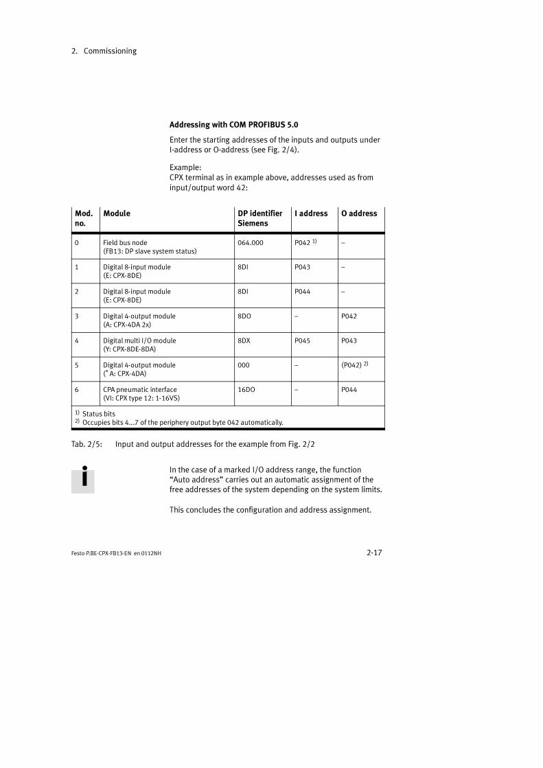
Addressing with COM PROFIBUS 5.0
Enter the starting addresses of the inputs and outputs underI-address or O-address (see Fig. 2/4).
Example:CPX terminal as in example above, addresses used as frominput/output word 42:
Mod.no.
Module DP identifierSiemens
I address O address
0 Field bus node(FB13: DP slave system status)
064.000 P042 1)
1 Digital 8-input module(E: CPX-8DE)
8DI P043
2 Digital 8-input module(E: CPX-8DE)
8DI P044
3 Digital 4-output module(A: CPX-4DA 2x)
8DO P042
4 Digital multi I/O module(Y: CPX-8DE-8DA)
8DX P045 P043
5 Digital 4-output module(* A: CPX-4DA)
000 (P042) 2)
6 CPA pneumatic interface(VI: CPX type 12: 1-16VS)
16DO P044
1) Status bits2) Occupies bits 4...7 of the periphery output byte 042 automatically.
Tab. 2/5: Input and output addresses for the example from Fig. 2/2
In the case of a marked I/O address range, the functionAuto address carries out an automatic assignment of thefree addresses of the system depending on the system limits.
This concludes the configuration and address assignment.

2. Commissioning
2-18 Festo P.BE-CPX-FB13-EN en 0112NH
STEP 7 V5.1 - Hardware configurator
Preparations
1. Copy the GSD file (see section 2.1.3) into directory...\STEP7\S7DATA\GSD on your PC or programmer.
The device master files (GSD) can either be copied man-ually into the above mentioned directory (e.g. with Win-dows Explorer) or
via the menu item Extras Install new GSD in thedialogue window HW Config.
Please noteUpdate the hardware catalogue, if you copy the devicemaster file (GSD) during work with STEP 7.
Menu in Hardware Config: Extras - Update catalog
Please noteAs from STEP 7 V4.02, device master files (GSD) are storedwithin the STEP 7 project (station GSD). This can cause theupdating/reading of new GSD files to appear as if incor-rect. Please inform yourself about handling the stationGSD files in the STEP 7 help.

2. Commissioning
2-19Festo P.BE-CPX-FB13-EN en 0112NH
Symbols 2. Copy the symbol files (see section 2.1.3) for the CPXterminal into directory ...\STEP7\S7DATA\NSBMP onyour PC or programmer.
The symbol files can either be copied
manually into the above-named directory or
read via the menu item Extras Install new GSD file type Bitmap in HW Config.
3. Process the following entries in the dialogue windowProperties of the DP Master:
the bus profile
the baud rate.
4. Activate the DP master in the rack.
2. Commissioning
2-20 Festo P.BE-CPX-FB13-EN en 0112NH
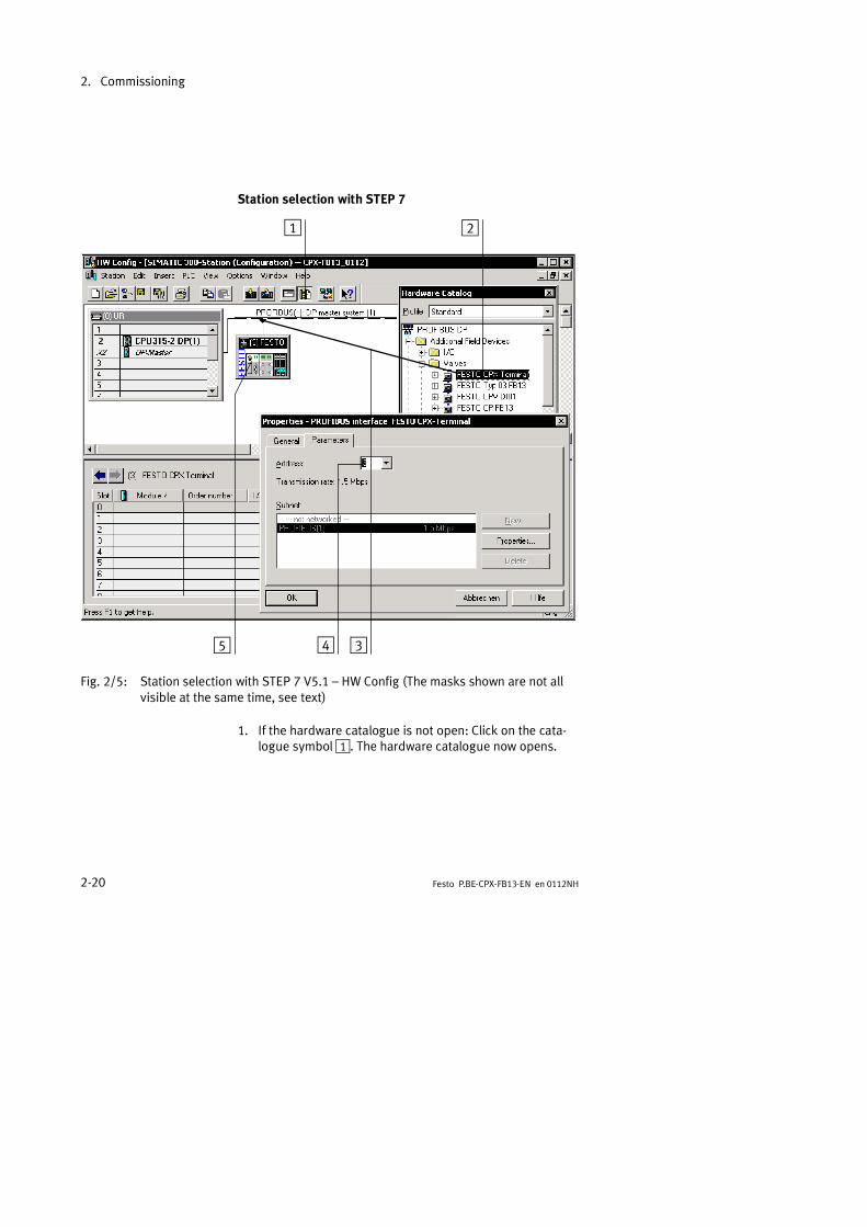
Station selection with STEP 7
1 2
345
Fig. 2/5: Station selection with STEP 7 V5.1 HW Config (The masks shown are not allvisible at the same time, see text)
1. If the hardware catalogue is not open: Click on the cata-logue symbol1. The hardware catalogue now opens.

2. Commissioning
2-21Festo P.BE-CPX-FB13-EN en 0112NH
2. In the hardware catalogue mark the folder FESTO CPX2 (...\PROFIBUS-DP\Additional Field Devices\Valves)with the left-hand mouse key.The slave type VALVES appears under folder Addi-tional Field Devices if you have copied the GSD correctly(see step 1 of the preparations).
3. Pull the folder FESTO CPX onto the PROFIBUS line onthe DP master (Drag & Drop)3.The dialogue window Properties PROFIBUS Interfaceappears.
4. Select the address identical to the selected setting of theDIL switch in the node (see Chapter 1.2.2)4 and confirmwith OK.The symbol of the CPX terminal appears on the PROFIBUSline5.
Configuration with STEP 7
Fill the configuration table with the modules of your CPX sys-tem (see Fig. 2/6):
1. Mark the symbol of the CPX terminal to be configured inHW Config.
2. Mark the first (left-hand) module of your CPX terminal inthe hardware catalogue. Pull it onto line 0 in the configur-ation table.
3. Repeat step 2 for further modules in your CPX terminal.You must pull these onto the next free line.
Please notePull the modules into the configuration table correspon-ding to their physical sequence on your CPX terminal(from left to right).
2. Commissioning
2-22 Festo P.BE-CPX-FB13-EN en 0112NH
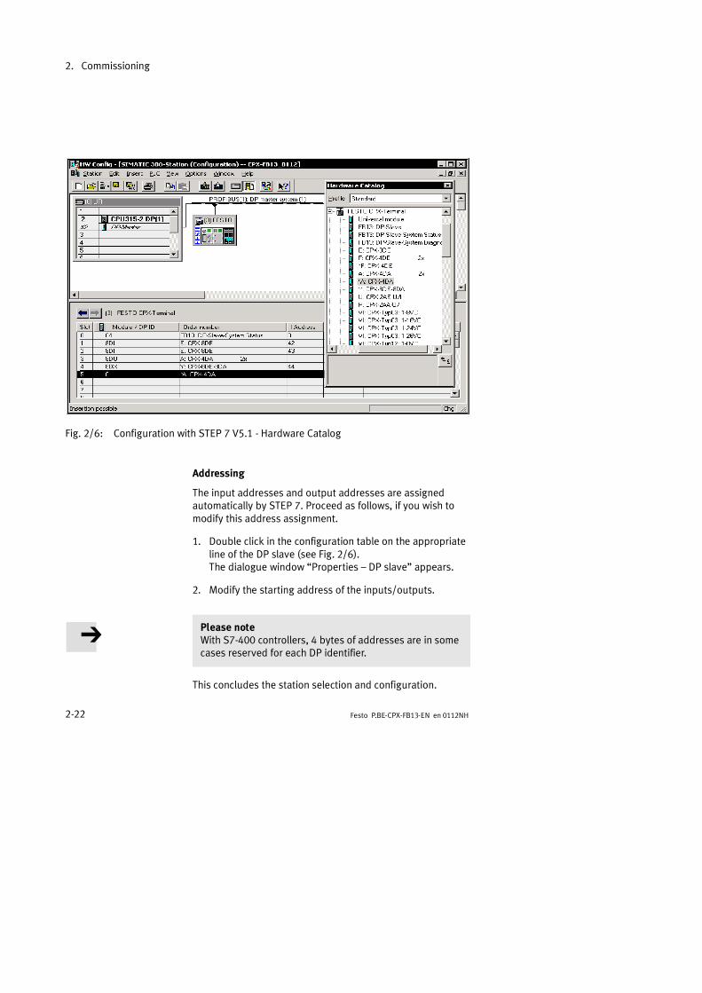
Fig. 2/6: Configuration with STEP 7 V5.1 - Hardware Catalog
Addressing
The input addresses and output addresses are assignedautomatically by STEP 7. Proceed as follows, if you wish tomodify this address assignment.
1. Double click in the configuration table on the appropriateline of the DP slave (see Fig. 2/6).The dialogue window Properties DP slave appears.
2. Modify the starting address of the inputs/outputs.
Please noteWith S7-400 controllers, 4 bytes of addresses are in somecases reserved for each DP identifier.
This concludes the station selection and configuration.

2. Commissioning
2-23Festo P.BE-CPX-FB13-EN en 0112NH
Addressing example
Example:CPX terminal as in Fig. 2/2, addresses used as from input/output word 42:
Loca-tion
Module DP identifierSiemens
I address O address
0 Field bus node(FB13: DP slave system status)
64 42
1 Digital 8-input module(E: CPX-8DE)
8DI 43
2 Digital 8-input module(E: CPX-8DE)
8DI 44
3 Digital 4-output module(A: CPX-4DA 2x)
8DO 42
4 Digital multi I/O module(Y: CPX-8DE-8DA)
8DX 45 43
5 Digital 4-output module(* A: CPX-4DA)
0 (42) *)
6 CPA pneumatic interface(VI: CPX type 12: 1-16VS)
16DO 44
*) Occupies bits 4...7 of output byte 042 automatically.
Tab. 2/6: Input and output addresses for the example from Fig. 2/2
2. Commissioning
2-24 Festo P.BE-CPX-FB13-EN en 0112NH
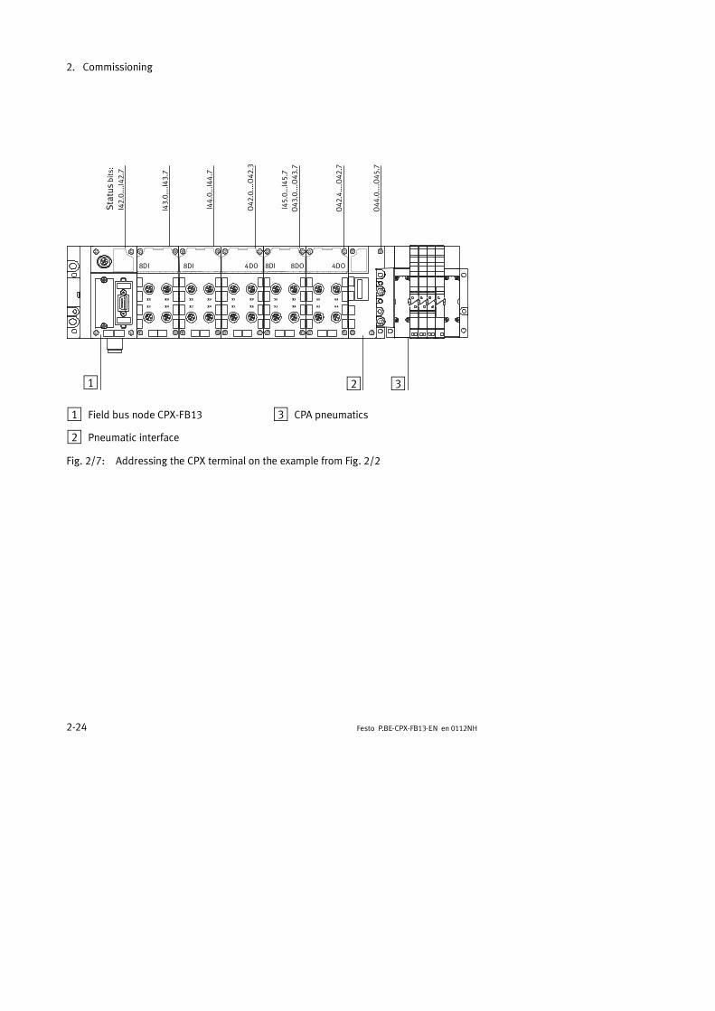
1 2
8DI 8DI 4DO 8DI 4DO
I43.0....I43.7
I44.0...I44
.7
3
O42
.0....O42
.3
O42
.4....O42
.7
O44
.0....O45
.7
I45.0...I45
.7O43
.0....O43
.7
Status
bits:
I42.0....I42.7
8DO
1 Field bus node CPX-FB13
2 Pneumatic interface
3 CPA pneumatics
Fig. 2/7: Addressing the CPX terminal on the example from Fig. 2/2

2. Commissioning
2-25Festo P.BE-CPX-FB13-EN en 0112NH
2.2 Parametrizing
You can set the reaction of the CPX terminal individually bymeans of parameters. A distinction is made between the fol-lowing parametrizings:
system parametrierung, e.g.: switching out error mess-ages, etc.
parametrizing the diagnostic memory
module parametrizing (module and channel-specific),e.g.: monitorings, settings in the event of faults, settingsthe debouncing times of the inputs.
A detailed description of the individual parameters as well asbasic information on application can be found in the CPX sys-tem manual (P.BE-CPX-SYS-..).Parameter lists for CPX I/O modules and CPX pneumatic in-terfaces can be found in the manual for the CPX I/O modules(P.BE-CPX-EA-..).
2.2.1 Parametrizing when the terminal is switched on
1 The parameterset is loaded intothe node by themaster.
2 The parameterset is distributedto the modulesby the node.
PLC/IPC
PROFI-BUS-DPMaster
1
2
Fig. 2/8: Sequence of the start parametrizing

2. Commissioning
2-26 Festo P.BE-CPX-FB13-EN en 0112NH
When the PROFIBUS system is switched on, the startparametrizing of the CPX terminal is undertaken by the para-meter set1 saved in the PROFIBUS master. The field busnode then distributes the parameters module-orientated tothe CPX modules2.
Please noteAfter each interruption of the field bus system (e.g. afterinterruption of the power supply to the field bus node), theparameter set will be sent again by the PROFIBUS masterto the field bus node.
An exchange of individual CPX modules is therefore possiblewithout the need once again for manual parametrizing.
2.2.2 Parametrizing the CPX terminal with STEP 7
System parameters
1. Double click the symbol of the CPX terminal on thePROFIBUS line1 (see Fig. 2/9).The dialogue window Properties - DP slave appears2.
2. Select the register Parameter assignment3.The list with the parameters and the present active valueswill be displayed.
3. Click the value of the parameter you wish to modify.A dropdown list with the possible values will open up4.
4. Modify the value by clicking and confirm with OK.

2. Commissioning
2-27Festo P.BE-CPX-FB13-EN en 0112NH
1 2 3 4
Fig. 2/9: Setting the system parameters with STEP 7
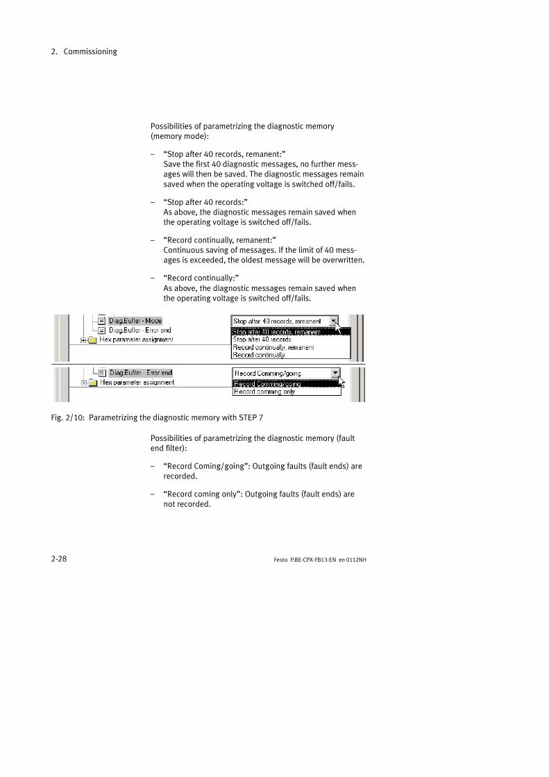
Parametrizing the diagnostic memory
Maximum 40 diagnostic messages can be saved in the diag-nostic memory. With the aid of the HW Config, DPV1 or thehandheld, you can parametrize the way in which the mess-ages are to be saved.
1. Click the value of the parameter Diag.Buffer Mode orDiag.Buffer Error endA dropdown list with the possible values will open up.
2. Modify the value as follows and confirm with OK.
2. Commissioning
2-28 Festo P.BE-CPX-FB13-EN en 0112NH
Possibilities of parametrizing the diagnostic memory(memory mode):
Stop after 40 records, remanent:Save the first 40 diagnostic messages, no further mess-ages will then be saved. The diagnostic messages remainsaved when the operating voltage is switched off/fails.
Stop after 40 records:As above, the diagnostic messages remain saved whenthe operating voltage is switched off/fails.
Record continually, remanent:Continuous saving of messages. If the limit of 40 mess-ages is exceeded, the oldest message will be overwritten.
Record continually:As above, the diagnostic messages remain saved whenthe operating voltage is switched off/fails.
Fig. 2/10: Parametrizing the diagnostic memory with STEP 7
Possibilities of parametrizing the diagnostic memory (faultend filter):
Record Coming/going: Outgoing faults (fault ends) arerecorded.
Record coming only: Outgoing faults (fault ends) arenot recorded.

2. Commissioning
2-29Festo P.BE-CPX-FB13-EN en 0112NH
Module parameters
1. Double click in the configuration table on the line of themodule you wish to parametrize1.The dialogue window Properties DP slave appears.
2. Proceed further as described in System parametersunder 3. and 4.
1
Fig. 2/11: Parametrizing the module with STEP 7
Please noteModule parameters can refer to:
features of the complete module
features of an individual channel of a module.

2. Commissioning
2-30 Festo P.BE-CPX-FB13-EN en 0112NH
2.2.3 Parametrizing with the handheld
The CPX handheld offers menu-orientated access to parame-trizing the CPX terminal without configuration software.
Information on operating the handheld can be found in theappropriate manual.
2.2.4 Application example of parametrizing
1 Input with defaultparametrizing
2 Input with reduc-tion of the inputdebounce timeand increase inthe signal exten-sion time
21
1. Sensor
2. Sensor
Fig. 2/12: Application example of parametrizing the debounce time and the pulse exten-sion (here on the right-hand sensor)
In the example above packets are transported on a fast con-veyor belt. With the following parametrizing, signal register-ing and processing are improved:
Reduction of the input debounce time of 3 ms (factorysetting) to 0.1 ms: It is possible to register shorter sig-nals. (Applies to the complete module).
Modification of the signal extension time to 50 ms: Thesignal is registered reliably by the controller. (Applies onlyto the input channel of the 2nd. sensor).

2. Commissioning
2-31Festo P.BE-CPX-FB13-EN en 0112NH
2.3 Commissioning the CPX terminal in the system
Please notePlease observe also the switching-on instructions in themanual for your controller.
Proceed as follows:
1. Connect the field bus cable to the CPX field bus node.
2. Switch on the operating voltage:
of all field bus slaves
of the CPX terminal.
3. Switch on the operating voltage for the master module.
Configuration run The master systems carry out a comparison between theNOMINAL and ACTUAL configurations (= DIL switch settingfor station number and modules used) automatically whenthe system is switched on. For this configuration run it is im-portant that:
the specifications for the NOMINAL configuration are com-plete and correct.
the power supply for the programmable logic controllerand for the field bus slaves is switched on either simulta-neously or in the sequence indicated above.
Recommendation:Providing the safety concept of your machine/system permitsthis, commission the CPX terminal with both operating volt-ages (pins 1 and 2), but without compressed air. You can thentest the CPX terminal without triggering undesired reactions.

2. Commissioning
2-32 Festo P.BE-CPX-FB13-EN en 0112NH
2.3.1 Faultless commissioning, normal operating status
After faultless commissioning the LEDs PS (power system)and PL (power load) light up green.Information on the other LEDs for diagnosis and error treat-ment can be found in chapter 3 of this manual and in the CPXsystem manual (P.BE-CPX-SYS-..).
LED Colour Operating status Error treatment
PS Greenlights up
Normal None
PL Greenlights up
Normal None
BF LED is off Normal None
Tab. 2/7: Normal operating status of the CPX terminal

Diagnosis
3-1Festo P.BE-CPX-FB13-EN en 0112NH
Chapter 3

3. Diagnosis
3-2 Festo P.BE-CPX-FB13-EN en 0112NH
Contents
3. Diagnosis 3-1. . . . . . . . . . . . . . . . . . . . . . . . . . . . . . . . . . . . . . . . . . . . . . . . . . . . .
3.1 Overview of diagnostic possibilities 3-4. . . . . . . . . . . . . . . . . . . . . . . . . . . . . . . .3.2 Diagnosis via LEDs 3-6. . . . . . . . . . . . . . . . . . . . . . . . . . . . . . . . . . . . . . . . . . . . . .
3.2.1 Fault displays of the bus fault/status LED BF 3-7. . . . . . . . . . . . . . . . .3.2.2 Error displays of the LEDs for system diagnosis PS, PL, SF, M 3-8. . . .
3.3 Diagnosis via status bits 3-11. . . . . . . . . . . . . . . . . . . . . . . . . . . . . . . . . . . . . . . . .3.4 Diagnosis via the I/O diagnostic interface 3-11. . . . . . . . . . . . . . . . . . . . . . . . . . .3.5 Diagnosis via PROFIBUS-DP 3-12. . . . . . . . . . . . . . . . . . . . . . . . . . . . . . . . . . . . . .
3.5.1 Diagnostic steps 3-13. . . . . . . . . . . . . . . . . . . . . . . . . . . . . . . . . . . . . . . .
3.5.2 Overview of diagnostic bytes 3-14. . . . . . . . . . . . . . . . . . . . . . . . . . . . . .3.5.3 Details on standard diagnostic information 3-18. . . . . . . . . . . . . . . . . . .3.5.4 Module-related diagnosis 3-20. . . . . . . . . . . . . . . . . . . . . . . . . . . . . . . . .3.5.5 Channel-related diagnosis 3-20. . . . . . . . . . . . . . . . . . . . . . . . . . . . . . . .
3.6 Error treatment (Fail safe) 3-23. . . . . . . . . . . . . . . . . . . . . . . . . . . . . . . . . . . . . .3.6.1 Siemens SIMATIC S5/S7 3-24. . . . . . . . . . . . . . . . . . . . . . . . . . . . . . . . . .
3.7 Online diagnosis with STEP 7 3-27. . . . . . . . . . . . . . . . . . . . . . . . . . . . . . . . . . . . .3.7.1 Read diagnostic buffer with STEP 7 (version 4.x, 5.1) 3-27. . . . . . . . . .3.7.2 Read device-specific diagnosis with STEP 7 (version 5.1) 3-29. . . . . . .

3. Diagnosis
3-3Festo P.BE-CPX-FB13-EN en 0112NH
Contents of this chapter The CPX terminal offers you extensive diagnostic possibilities.In this chapter you will find an overview of as well as detailedinformation on the diagnostic possibilities with:
LEDs
status bits
the I/O diagnostic interface
PROFIBUS-DP
the handheld.
Further information Information on general diagnosis of the CPX terminal can befound in the CPX system manual (P.BE-CPX-SYS-..).
Information on diagnosing the pneumatic interface and theI/O modules can be found in the manual CPX I/O modules(P.BE-CPX-EA-..).
Information on diagnosing the pneumatics can be found inthe relevant pneumatics manual.

3. Diagnosis
3-4 Festo P.BE-CPX-FB13-EN en 0112NH
3.1 Overview of diagnostic possibilities
The CPX terminal offers extensive and user-friendly possibi-lities of diagnosis and error treatment. The following possibi-lities are available depending on the configuration:
Diagnosticpossibility
Brief description Advantages Detaileddescription
LED display The LEDs show directly con-figuration faults, hardwarefaults, bus faults, etc.
Fast on-the-spot faultrecognition
Section 3.2
Status bits Internal inputs which sup-ply coded common diag-nostic messages.The 8 status bits are trans-mitted to the module asinputs cyclically with thenormal inputs.
Fast access to error mess-ages in the PLC user pro-gram, irrespective of themodule and the master.
Section 3.3
Diagnosis viaPROFIBUS-DP
Diagnosis as per PROFIBUSstandard
Detailed module-relatedand channel-related faultrecognition in the onlinemode of the programming/configuration software andin the PLC user program.
Section 3.5
Diagnosis withPROFIBUS DPV1
Access to all system data ofthe CPX terminal via thefield bus.
Extended access to diag-nostic data in the PLC userprogram (e.g. diagnosticmemory).
Appendix A.3
Tab. 3/1: Diagnostic possibilities part 1

3. Diagnosis
3-5Festo P.BE-CPX-FB13-EN en 0112NH
Diagnosticpossibility
Brief description Advantages Detaileddescription
I/O diagnosticinterface
Bus-independent diagnos-tic interface at I/O levelwhich permits access tointernal data of the CPXterminal (16 inputs and16 outputs).
Read access to internalparameters and data atI/O level.
CPX systemmanual(P.BE-CPX-SYS-..)
Diagnosis with thehandheld
Convenient and menu-listed diagnostic informa-tion can be displayed onthe CPX handheld.
Fast on-the-spot faultrecognition without pro-gramming in clear text.
Manual for thehandheld
Tab. 3/2: Diagnostic possibilities part 2
Please noteNote that the diagnostic information shown can depend onthe settings (see section 1.2.2) as well as on the parame-trizing (see section 2.2) of the CPX terminal.

3. Diagnosis
3-6 Festo P.BE-CPX-FB13-EN en 0112NH
3.2 Diagnosis via LEDs
The LEDs on the cover indicate the operating status of theCPX field bus node.
1 LED BF: Busfault/status (red)
2 LEDs for the sys-tem diagnosis:PS: Power system(green)PL: Power load(green)SF: System fault(red)M: Modify(yellow)
BF PS
PL
SF
M
1
2
Fig. 3/1: LEDs of the CPX node
The LEDs in their various states are represented as follows:
lights up ; flashes ; out
3. Diagnosis
3-7Festo P.BE-CPX-FB13-EN en 0112NH
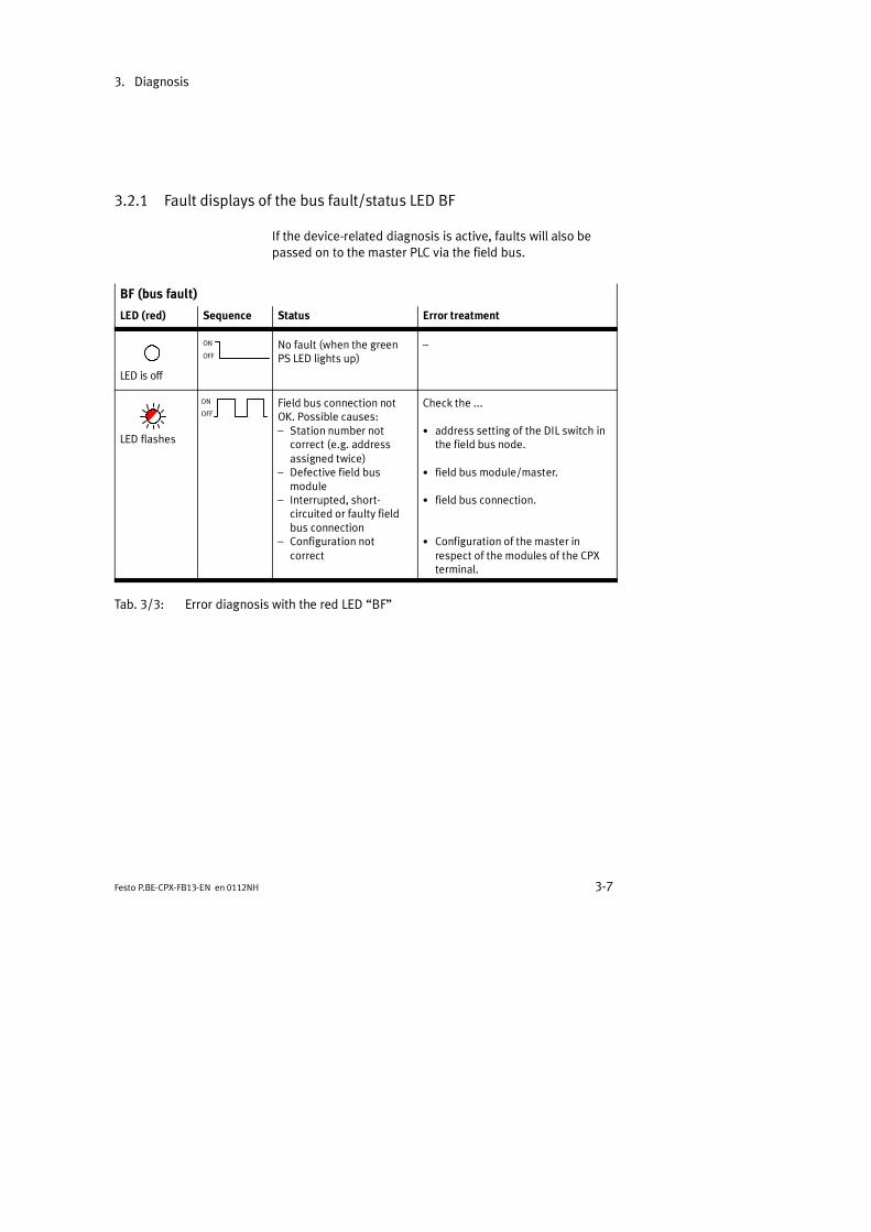
3.2.1 Fault displays of the bus fault/status LED BF
If the device-related diagnosis is active, faults will also bepassed on to the master PLC via the field bus.
BF (bus fault)
LED (red) Sequence Status Error treatment
LED is off
ON
OFFNo fault (when the greenPS LED lights up)
LED flashes
ON
OFFField bus connection notOK. Possible causes: Station number not
correct (e.g. addressassigned twice)
Defective field busmodule
Interrupted, short-circuited or faulty fieldbus connection
Configuration notcorrect
Check the ...
address setting of the DIL switch inthe field bus node.
field bus module/master.
field bus connection.
Configuration of the master inrespect of the modules of the CPXterminal.
Tab. 3/3: Error diagnosis with the red LED BF
3. Diagnosis
3-8 Festo P.BE-CPX-FB13-EN en 0112NH
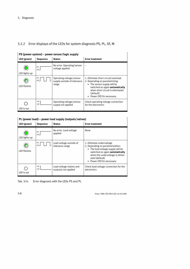
3.2.2 Error displays of the LEDs for system diagnosis PS, PL, SF, M
PS (power system) power sensor/logic supply
LED (green) Sequence Status Error treatment
LED lights up
ON
OFF
No error. Operating/sensorvoltage applied
LED flashes
ON
OFFOperating voltage/sensorsupply outside of tolerancerange
1. Eliminate short circuit/overload2. Depending on parametrizing:
The sensor supply will beswitched on again automaticallywhen short circuit is eliminated(default)
Power Off/On necessary
LED is out
ON
OFFOperating voltage/sensorsupply not applied
Check operating voltage connectionfor the electronics
PL (power load) power load supply (outputs/valves)
LED (green) Sequence Status Error treatment
LED lights up
ON
OFF
No error. Load voltageapplied
None
LED flashes
ON
OFFLoad voltage outside oftolerance range
1. Eliminate undervoltage2. Depending on parametrization:
The load voltage supply will beswitched on again automaticallywhen the undervoltage is elimin-ated (default)
Power Off/On necessary
LED is out
ON
OFFLoad voltage (valves andoutputs) not applied
Check load voltage connection for theelectronics
Tab. 3/4: Error diagnosis with the LEDs PS and PL
3. Diagnosis
3-9Festo P.BE-CPX-FB13-EN en 0112NH
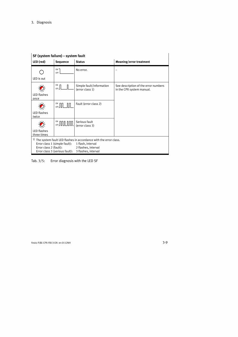
SF (system failure) system fault
LED (red) Sequence Status Meaning/error treatment
LED is out
ON
OFFNo error.
LED flashesonce
ON
OFFSimple fault/information(error class 1)
See description of the error numbersin the CPX system manual.
LED flashestwice
ON
OFFFault (error class 2)
LED flashesthree times
ON
OFFSerious fault(error class 3)
1) The system fault LED flashes in accordance with the error class.Error class 1 (simple fault): 1 flash, intervalError class 2 (fault): 2 flashes, intervalError class 3 (serious fault): 3 flashes, interval
Tab. 3/5: Error diagnosis with the LED SF
3. Diagnosis
3-10 Festo P.BE-CPX-FB13-EN en 0112NH
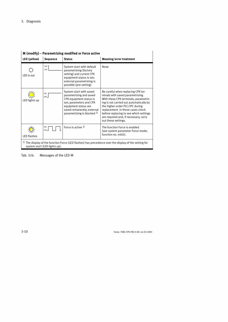
M (modify) Parametrizing modified or Force active
LED (yellow) Sequence Status Meaning/error treatment
LED is out
ON
OFFSystem start with defaultparametrizing (factorysetting) and current CPXequipment status is set;external parametrizing ispossible (pre-setting)
None
LED lights up
ON
OFF
System start with savedparametrizing and savedCPX equipment status isset; parameters and CPXequipment status aresaved remanently; externalparametrizing is blocked 1)
Be careful when replacing CPX ter-minals with saved parametrizing.With these CPX terminals, parametriz-ing is not carried out automatically bythe higher-order PLC/IPC duringreplacement. In these cases checkbefore replacing to see which settingsare required and, if necessary, carryout these settings.
LED flashes
ON
OFFForce is active 1) The function Force is enabled
(see system parameter Force mode;function no. 4402).
1) The display of the function Force (LED flashes) has precedence over the display of the setting forsystem start (LED lights up).
Tab. 3/6: Messages of the LED M

3. Diagnosis
3-11Festo P.BE-CPX-FB13-EN en 0112NH
3.3 Diagnosis via status bits
The CPX terminal will provide 8 status bits if you haveparametrized it with option FB13 DP slave system status.The status bits serve for displaying common diagnostic mess-ages (global error messages). They are configured like in-puts; you can select the address when configuring.If all status bits supply a 0-signal, no fault will be registered.
Bit Diagnostic informationwith 1-signal
Description
0 Fault at valve Module type with which af lt h d
1 Fault at outputfault has occurred.
2 Fault at input
3 Fault in analogue module/function module
4 Undervoltage Type of fault
5 Short circuit/overload
6 Wire fracture
7 Other faults
Tab. 3/7: Status bits of the CPX FB13 (optional)
3.4 Diagnosis via the I/O diagnostic interface
The CPX terminal will provide a 16-bit diagnostic interface ifyou have configured it with option FB13 DP slave systemdiagnosis.
Information on the I/O diagnostic interface can be found inthe CPX system manual P.BE-CPX-SYS-.. .

3. Diagnosis
3-12 Festo P.BE-CPX-FB13-EN en 0112NH
3.5 Diagnosis via PROFIBUS-DP
The CPX terminal supports the following diagnostic possibi-lities via PROFIBUS as per EN 50170:
Device-related diagnosis:Status message (see also section 3.7.2)
Module-related diagnosis (see section 3.5.4).One bit is reserved pro module for displaying a currentdiagnosis.
Channel-related diagnosis (see section 3.5.5).- module number- channel number and type- type of diagnosis (fault number).
1
2 3
1 Device-related diagnosis
2 Module-related diagnosis
3 Channel-related diagnosis
Fig. 3/2: Diagnostic possibilities
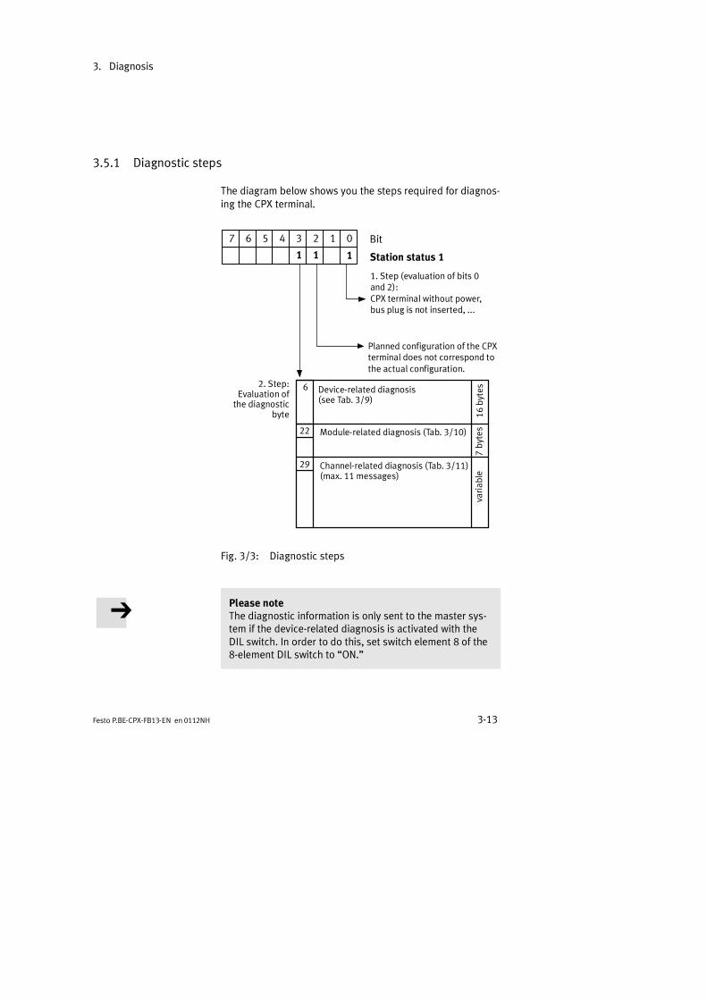
3. Diagnosis
3-13Festo P.BE-CPX-FB13-EN en 0112NH
3.5.1 Diagnostic steps
The diagram below shows you the steps required for diagnos-ing the CPX terminal.
22
123 04567
1
Bit
Station status 1
1. Step (evaluation of bits 0and 2):CPX terminal without power,bus plug is not inserted, ...
1
Planned configuration of the CPXterminal does not correspond tothe actual configuration.
2. Step:Evaluation of
the diagnosticbyte
1
Device-related diagnosis(see Tab. 3/9)
Module-related diagnosis (Tab. 3/10)
Channel-related diagnosis (Tab. 3/11)(max. 11 messages)
7by
tes
varia
ble
16by
tes6
29
Fig. 3/3: Diagnostic steps
Please noteThe diagnostic information is only sent to the master sys-tem if the device-related diagnosis is activated with theDIL switch. In order to do this, set switch element 8 of the8-element DIL switch to ON.
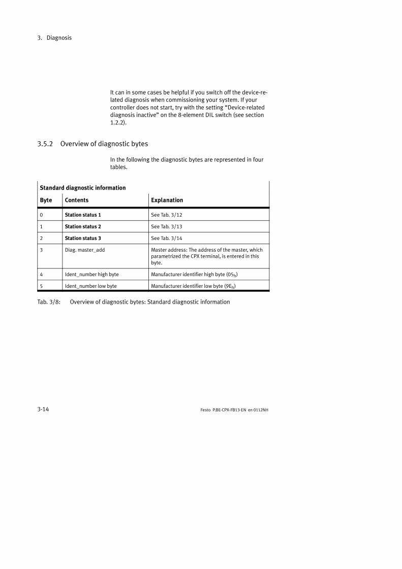
3. Diagnosis
3-14 Festo P.BE-CPX-FB13-EN en 0112NH
It can in some cases be helpful if you switch off the device-re-lated diagnosis when commissioning your system. If yourcontroller does not start, try with the setting Device-relateddiagnosis inactive on the 8-element DIL switch (see section1.2.2).
3.5.2 Overview of diagnostic bytes
In the following the diagnostic bytes are represented in fourtables.
Standard diagnostic information
Byte Contents Explanation
0 Station status 1 See Tab. 3/12
1 Station status 2 See Tab. 3/13
2 Station status 3 See Tab. 3/14
3 Diag. master_add Master address: The address of the master, whichparametrized the CPX terminal, is entered in thisbyte.
4 Ident_number high byte Manufacturer identifier high byte (05h)
5 Ident_number low byte Manufacturer identifier low byte (9Eh)
Tab. 3/8: Overview of diagnostic bytes: Standard diagnostic information

3. Diagnosis
3-15Festo P.BE-CPX-FB13-EN en 0112NH
Device-related diagnosis (16 bytes), (module status DPV1)
Byte Contents Explanation
6 Header On the CPX terminal fixed Ch
7 Type On the CPX terminal fixed 82h
8 Slot On the CPX terminal fixed 0h
9 Slot On the CPX terminal fixed 0h
10 Module 0 (bits 1 and 2)...Module 3 (bits 6 and 7)
2 bits per module:00 = No fault (valid work data)01 = Module fault (work data invalid)10 = Incorrect module (work data invalid)11 = Module has failed or does not exist
(work data invalid)
11 Modules 4...7 Like byte 10
12 Modules 8...10(bits 6 and 7 are reserved)
Like byte 10
13...21 Reserved
Tab. 3/9: Overview of device-related diagnosis (fixed at length of 16 bytes)

3. Diagnosis
3-16 Festo P.BE-CPX-FB13-EN en 0112NH
Module-related diagnosis (7 bytes)
Byte Contents Explanation
22 Header On the CPX terminal fixed 47h
23 Module-related diagnostic modules 0...7 The relevant module has diagnosticmessage
24 Module-related diagnostic modules 8...10 The relevant module has diagnosticmessage
25...28 Reserved
Tab. 3/10: Overview of diagnostic bytes: Module-related diagnosis (details in section 3.5.4)
Channel-related diagnosis (variable length)
Byte Contents Explanation
29 Channel-related diagnostic module x byte 1 Contains module number
30 Channel-related diagnostic module x byte 2 Channel number and input/output
31 Channel-related diagnostic module x byte 3 Fault type and channel type
32 Channel-related diagnostic module y byte 1 Contains module number
33 Channel-related diagnostic module y byte 2 Channel number and input/output
34 Channel-related diagnostic module y byte 3 Fault type and channel type
... ... ...
59 Channel-related diagnostic module z byte 1 Contains module number
60 Channel-related diagnostic module z byte 2 Channel number and input/output
61 Channel-related diagnostic module z byte 3 Fault type and channel type
x, y, z: See explanation in the following text.
Tab. 3/11: Overview of diagnostic bytes: Channel-related diagnosis (details in section 3.5.5)

3. Diagnosis
3-17Festo P.BE-CPX-FB13-EN en 0112NH
The following applies for the entries in the diagnostic bytes29...61 of the channel-related diagnosis:
Entry according to module numbers in ascending orderand without gaps: The entries are always listed accordingto the module numbers, irrespective of the time sequenceof the diagnostic messages (if necessary, the entries withhigher module numbers will be postponed).
In the case of module-orientated and channel-orientatedfaults on a module, only the module-orientated diagnosticmessage will be entered.
In the case of several channel-orientated faults on a mod-ule, only the diagnostic message of the channel with thelowest channel number will be entered.
Maximum 11 diagnostic messages can be processed.

3. Diagnosis
3-18 Festo P.BE-CPX-FB13-EN en 0112NH
3.5.3 Details on standard diagnostic information
The following diagnostic information can be requested bythe DP master from the CPX terminal with the functionSlave_Diag . The procedure for reading out this diagnosticinformation with a SIMATIC S5/S7 system is described in-chapter 3.6.1.
Station status_1
Bit Meaning Explanation
0 *) Diag.Station_Non_Existent CPX terminal is no longer/not yet addressable.Possible causes: operating voltage not applied data cable interrupted fault in data cable
1 *) Diag.Station_Not_Ready CPX terminal is not yet ready for data exchange
2 *) Diag.Cfg_Fault The configuration data received from the master do notagree with those ascertained by the CPX terminal.
3 *) Diag.Ext_Diag There is a diagnosis. Possible causes: cable fracture on input/output module short circuit/overload at electric outputs, ...
4 Diag.Not_Supported 1 = CPX terminal does not support the function requested
5 Diag.Invalid_Slave_Response Always 0 (set by CPX terminal)
6 Diag.Prm_Fault Last parametrizing telegram faulty
7 Diag.Master_Lock Always 0 (set by CPX terminal)
*) Valve terminal related bits
Tab. 3/12: Diagnostic bits Station status_1
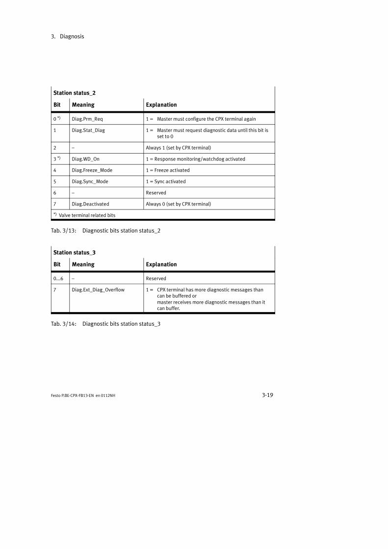
3. Diagnosis
3-19Festo P.BE-CPX-FB13-EN en 0112NH
Station status_2
Bit Meaning Explanation
0 *) Diag.Prm_Req 1 = Master must configure the CPX terminal again
1 Diag.Stat_Diag 1 = Master must request diagnostic data until this bit isset to 0
2 Always 1 (set by CPX terminal)
3 *) Diag.WD_On 1 = Response monitoring/watchdog activated
4 Diag.Freeze_Mode 1 = Freeze activated
5 Diag.Sync_Mode 1 = Sync activated
6 Reserved
7 Diag.Deactivated Always 0 (set by CPX terminal)
*) Valve terminal related bits
Tab. 3/13: Diagnostic bits station status_2
Station status_3
Bit Meaning Explanation
0...6 Reserved
7 Diag.Ext_Diag_Overflow 1 = CPX terminal has more diagnostic messages thancan be buffered ormaster receives more diagnostic messages than itcan buffer.
Tab. 3/14: Diagnostic bits station status_3

3. Diagnosis
3-20 Festo P.BE-CPX-FB13-EN en 0112NH
3.5.4 Module-related diagnosis
One bit is reserved for each module assigned during the con-figuration (identifier byte). A set bit means that there is adiagnostic message in this I/O range.
5 123 0467 Bit Header byte of the module-relateddiagnosis
Length of the module-related diagnosticrecord in bytes inclusive header byte.
1
Bit 7, 6 fixed at 01
0 1110 0 0
Fig. 3/4: Header byte of the module-related diagnosis
5 123 0467 BitModule-related diagnosis
Module 0 has diagnosis
Module 1 has diagnosis
Module 7 has diagnosis
...
...
Fig. 3/5: Module-related diagnosis
3.5.5 Channel-related diagnosis
3 bytes of diagnostic data are available for each channel.
Byte 1: Module number
Byte 2: Channel number
Byte 3: Type of diagnosis

3. Diagnosis
3-21Festo P.BE-CPX-FB13-EN en 0112NH
Bit 7, 6 fixed at 10
5 123 0467 Bit Module number of the channel-relateddiagnosis
Module number 0...63
01
Fig. 3/6: Channel-related diagnostic byte 1
5 123 0467 Bit Channel number
Channel number 0...63
Input/output00 = reserved 10 = output01 = input 11 = input/output
Fig. 3/7: Channel-related diagnostic byte 2
5 123 0467 Bit Type of diagnosis
Fault type (see Tab. 3/15)
Channel type000 = reserved 100 = 1 byte001 = 1 bit 101 = 1 word010 = 2 bits 110 = 2 words011 = 4 bits 111 = reserved
Fig. 3/8: Channel-related diagnostic byte 3

3. Diagnosis
3-22 Festo P.BE-CPX-FB13-EN en 0112NH
Value Fault type (standard) Value Fault type (Festo)
0 Reserved 16 Valve setting incorrect
1 Short circuit 17 Valve: Switching cycle counter, limitexceeded
2 Undervoltage 18 Reserved
3 Overvoltage 19 Reserved
4 Overload 20 Parametrizing fault (configurable)
5 Overtemperature 21 Parametrizing fault (data format)
6 Cable fracture 22 Parametrizing fault (linear scaling)
7 Switching cycle counter, limitexceeded
23 Parametrizing fault (digital filter)
8 Lower limit exceeded 24 Parametrizing fault (lower limit)
9 Reserved 25 Parametrizing fault (upper limit)
10 Reserved 26 Reserved
11 Reserved 27 Reserved
12 Reserved 28 Reserved
13 Reserved 29 Reserved
14 Reserved 30 Slave has no bus connection
15 Reserved 31 Channel failure
Tab. 3/15: Fault types (byte 3 of the channel-related diagnosis)

3. Diagnosis
3-23Festo P.BE-CPX-FB13-EN en 0112NH
3.6 Error treatment (Fail safe)
Parametrizing With the following faults, the reaction of the CPX terminaldepends on the configured reaction of the master moduleand the parametrized Fail safe setting:
telegram failure
master stopped
interruption in bus cable.
Depending on the parametrizing, the outputs (valves andelectric outputs) will be switched off (factory setting),switched on or retain their status (see CPX system manual).
Warning Make sure that valves and outputs are put into a safestate when the faults named occur.
An incorrect status of the valves and outputs may lead todangerous situations.
Further information on the fail-safe setting can be found inthe CPX system manual P.BE-CPX-SYS-.. .
Please noteIf the outputs are reset in the event of a PLC stop, field businterruption or field bus fault, please observe the follow-ing:
Single-solenoid valves move to the basic position.
Double-solenoid valves remain in the current position.
Mid-position valves move to the mid-position (depend-ing on valve type: pressurized, exhausted or blocked).
3. Diagnosis
3-24 Festo P.BE-CPX-FB13-EN en 0112NH
3.6.1 Siemens SIMATIC S5/S7
With these controllers, you have the possibility of determin-ing the reaction of the CPX terminal to the faults named (de-tails see controller manual).
Almost all configuration programs contain the functionResponse monitoring. For the operating modes named, thetime specified corresponds to the drop-off time of the valvesand electric outputs.
Further details on response monitoring can be found in therelevant manuals.

3. Diagnosis
3-25Festo P.BE-CPX-FB13-EN en 0112NH
You can set two ways in which the control system reacts tofaults:
when a fault occurs, the controller switches to the operat-ing mode STOP (hard fault reaction) or
when a fault occurs, the controller remains in the operat-ing mode RUN (soft fault reaction).
Control system Module Meaning STOP RUN
SIMATIC S5with IM 308C
OB23 Reaction to QVZ withdirect periphery access
default OB is programmed
OB24 Reaction to QVZ withperiphery access viaprocess image
default OB is programmed
OB35 Reaction to PEU default OB is programmed
SIMATIC S7/M7 OB82 Reaction to a device-specific diagnosis
default OB is programmed
OB86 Reaction to failure of aDP slave
default OB is programmed
QVZ: Quitting delayOB: Organisation modulePEU: Periphery not clear
Tab. 3/16: Fault reaction of the control system
Further details can be found in the relevant manuals for thecontrol systems.
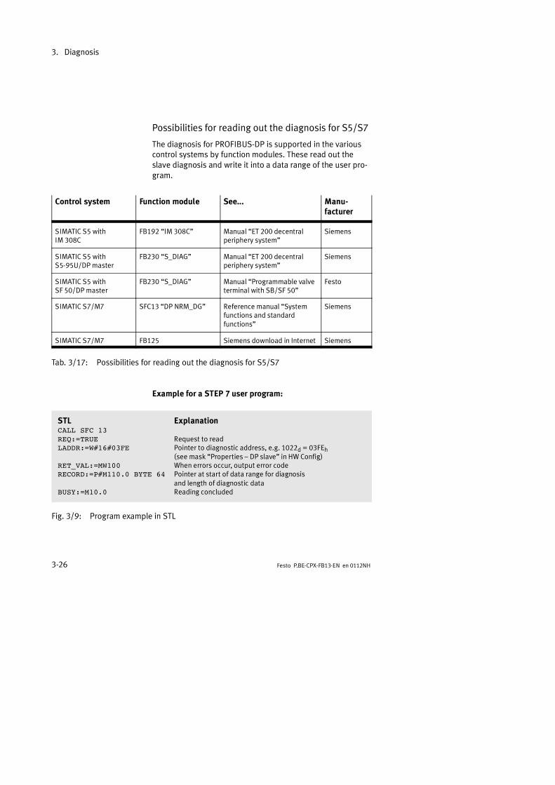
3. Diagnosis
3-26 Festo P.BE-CPX-FB13-EN en 0112NH
Possibilities for reading out the diagnosis for S5/S7
The diagnosis for PROFIBUS-DP is supported in the variouscontrol systems by function modules. These read out theslave diagnosis and write it into a data range of the user pro-gram.
Control system Function module See... Manu-facturer
SIMATIC S5 withIM 308C
FB192 IM 308C Manual ET 200 decentralperiphery system
Siemens
SIMATIC S5 withS5-95U/DP master
FB230 S_DIAG Manual ET 200 decentralperiphery system
Siemens
SIMATIC S5 withSF 50/DP master
FB230 S_DIAG Manual Programmable valveterminal with SB/SF 50
Festo
SIMATIC S7/M7 SFC13 DP NRM_DG Reference manual Systemfunctions and standardfunctions
Siemens
SIMATIC S7/M7 FB125 Siemens download in Internet Siemens
Tab. 3/17: Possibilities for reading out the diagnosis for S5/S7
Example for a STEP 7 user program:
STL ExplanationCALL SFC 13REQ:=TRUE Request to readLADDR:=W#16#03FE Pointer to diagnostic address, e.g. 1022d = 03FEh
(see mask Properties DP slave in HW Config)RET_VAL:=MW100 When errors occur, output error codeRECORD:=P#M110.0 BYTE 64 Pointer at start of data range for diagnosis
and length of diagnostic dataBUSY:=M10.0 Reading concluded
Fig. 3/9: Program example in STL

3. Diagnosis
3-27Festo P.BE-CPX-FB13-EN en 0112NH
3.7 Online diagnosis with STEP 7
Direct diagnostic events in conjunction with the CPX terminalcan be:
Decentral periphery: Station failure.Communication between slave and master is interrupted.
Component faulty (see device-related diagnosis,Tab. 3/9).
Operating status transition from START to RUN (nominal/actual difference exists):
Configuration data of the CPX node do not correspondwith the periphery.
Incorrect DIL switch setting in the CPX node.
3.7.1 Read diagnostic buffer with STEP 7 (version 4.x, 5.1)
Prerequisites:
HW Config has been accessed
Proceed as follows (Fig. 3/10):
1. Switch from offline to online1.
2. Click with the right-hand mouse button on the CPU in therack 2. Click on Module information in the contextmenu which now appears.The dialogue window Module information appears3.
3. Select the register Diagnostic Buffer4.
4. Mark the event and read the details on the event. Thesesupply more detailed information on the further pro-cedure and depend on the S7 controller 5 used.

3. Diagnosis
3-28 Festo P.BE-CPX-FB13-EN en 0112NH
1 2 3 4
56
Fig. 3/10: Online diagnosis via diagnostic buffer (explanation see text)
3. Diagnosis
3-29Festo P.BE-CPX-FB13-EN en 0112NH
3.7.2 Read device-specific diagnosis with STEP 7 (version 5.1)
You can display error messages of the device-specific diag-nosis with STEP 7 HW Config V5.1, if you mark the CPX ter-minal instead of the CPU.Proceed as follows (see Fig. 3/11):
Prerequisites: HW Config has been accessed.
1. Switch from offline to online.
2. Click with the right-hand mouse key on the symbol of theCPX terminal1. Click on Module information in the con-text menu which now appears.The dialogue window Module information appears.
3. Select the register DP Slave Diagnostics.
4. Read the diagnostic information2.
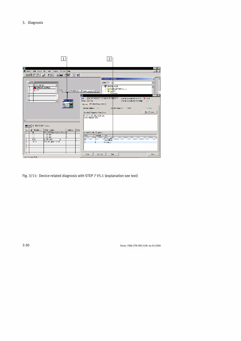
3. Diagnosis
3-30 Festo P.BE-CPX-FB13-EN en 0112NH
1 2
Fig. 3/11: Device-related diagnosis with STEP 7 V5.1 (explanation see text)

Technical appendix
A-1Festo P.BE-CPX-FB13-EN en 0112NH
Appendix A

A. Technical appendix
A-2 Festo P.BE-CPX-FB13-EN en 0112NH
Contents
A. Technical appendix A-1. . . . . . . . . . . . . . . . . . . . . . . . . . . . . . . . . . . . . . . . . . . . .
A.1 Technical specifications of field bus node CPX-FB13 A-3. . . . . . . . . . . . . . . . . . .A.2 Operation with the general DP master A-4. . . . . . . . . . . . . . . . . . . . . . . . . . . . . .
A.2.1 Bus start A-4. . . . . . . . . . . . . . . . . . . . . . . . . . . . . . . . . . . . . . . . . . . . . . .A.2.2 Send parametriziung data A-5. . . . . . . . . . . . . . . . . . . . . . . . . . . . . . . .
A.2.3 Send configuration data A-7. . . . . . . . . . . . . . . . . . . . . . . . . . . . . . . . . .A.2.4 Error treatment A-10. . . . . . . . . . . . . . . . . . . . . . . . . . . . . . . . . . . . . . . . .A.2.5 Request diagnostic information A-10. . . . . . . . . . . . . . . . . . . . . . . . . . . .A.2.6 Start cyclic exchange of data A-10. . . . . . . . . . . . . . . . . . . . . . . . . . . . . .
A.2.7 Implemented functions and service access points (SAP) A-12. . . . . . . .A.2.8 Bus parameters/reaction times A-13. . . . . . . . . . . . . . . . . . . . . . . . . . . .A.2.9 Transmission times on the PROFIBUS-DP A-13. . . . . . . . . . . . . . . . . . . .
A.3 Access to the CPX terminal via DPV1 A-14. . . . . . . . . . . . . . . . . . . . . . . . . . . . . . .
A.3.1 Reading and writing data records A-14. . . . . . . . . . . . . . . . . . . . . . . . . .A.3.2 Data records A-17. . . . . . . . . . . . . . . . . . . . . . . . . . . . . . . . . . . . . . . . . . .

A. Technical appendix
A-3Festo P.BE-CPX-FB13-EN en 0112NH
A.1 Technical specifications of field bus node CPX-FB13
General
General technical specifications See CPX system manual: P.BE-CPX-SYS-..
Protection class as per EN 60529, CPX-FB13 fittedcompletely, plug connector inserted or providedwith protective cap
IP65
Protection against electric shock(protection against direct and indirect contact asper EN 60204-1/IEC 204)
By means of PELV power units(Protected Extra-Low Voltage)
Module code (CPX-specific) 202
Power supply
Operating voltage / Load voltage See CPX system manual: P.BE-CPX-SYS-..
Current consumption of field bus node CPX-FB13 From operating voltage supply for electronics/
sensors (VSEN)Max. 200 mA (only CPX-FB13)
Electrical isolation Bus interface opto-decoupled
Field bus
PROFIBUS chip SPC 3 with DPV1
Design RS 485, floating
Transmission type Serial asynchronous, half-duplex
Protocol PROFIBUS-DP
Baud rate 9.6...12000 kBaud, automatic baud raterecognition
Cable type Depending on cable length and field bus baudrate set: see controller manual

A. Technical appendix
A-4 Festo P.BE-CPX-FB13-EN en 0112NH
A.2 Operation with the general DP master
The Festo CPX terminal can be controlled from any PLC, PC orindustrial PC with a PROFIBUS-DP module in accordance withEN 50170 (DIN 19245).
Information on the functions FREEZE, SYNC and the DP ident-ifiers can be found in section 2.1.1.
A.2.1 Bus start
In order to commission the CPX terminal correctly, the DPmaster must carry out the following functions in the sequencespecified:
1. Request diagnosis.
2. Send parametrizing data.In the case of the start parametrizing, the parameter setwill be loaded into the field bus node by the master. Thenode distributes the parameters to the modules.
3. Send configuration data.
4. Diagnosis request before data exchange.
5. Start cyclic exchange of data.
The composition and contents of the individual telegrams aredescribed in the following sections.
Please noteAfter each interruption of the field bus system (e.g. afterinterruption of the power supply to the field bus node), theparameter set will be sent again by the PROFIBUS masterto the field bus node.
An exchange of individual CPX modules is therefore possiblewithout the need for manual parametrizing.

A. Technical appendix
A-5Festo P.BE-CPX-FB13-EN en 0112NH
A.2.2 Send parametrizing data
Set_Prm The parametrizing data are sent to the CPX terminal by the DPmaster with the function Set_Prm.
Octet 1: Station status
Bit Meaning Explanation
0 Reserved
1
2
3 WD_On Response monitoring of the CPX terminal on/off:0 = Off1 = On
4 Freeze_Req 0 = Freeze mode not requested by the master1 = Freeze mode set by the master
5 Sync_Req 0 = Sync mode not requested by the master1 = Sync mode set by the master
6 Unlock_Req Bit 7 Bit 6 Explanation
7 Lock_Req 0 0 Min TSDR + slave parameter may be overwritten
0 1 CPX terminal released for other masters
1 0 CPX terminal blocked for other masters
1 1 CPX terminal released for other masters
Tab. A/1: Octet 1: Station status
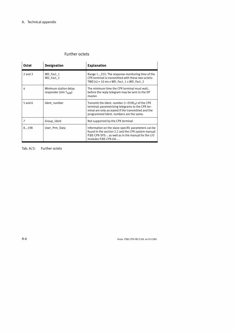
A. Technical appendix
A-6 Festo P.BE-CPX-FB13-EN en 0112NH
Further octets
Octet Designation Explanation
2 and 3 WD_Fact_1WD_Fact_2
Range 1...255: The response monitoring time of theCPX terminal is transmitted with these two octets:TWD [s] = 10 ms x WD_Fact_1 x WD_Fact_2
4 Minimum station delayresponder (min TSDR)
The minimum time the CPX terminal must wait,before the reply telegram may be sent to the DPmaster.
5 and 6 Ident_number Transmit the Ident. number (= 059EH) of the CPXterminal; parametrizing telegrams to the CPX ter-minal are only accepted if the transmitted and theprogrammed Ident. numbers are the same.
7 Group_Ident Not supported by the CPX terminal
8...198 User_Prm_Data Information on the slave-specific parameters can befound in the section 2.2 and the CPX system manualP.BE-CPX-SYS-.. as well as in the manual for the I/Omodules P.BE-CPX-EA-.. .
Tab. A/2: Further octets

A. Technical appendix
A-7Festo P.BE-CPX-FB13-EN en 0112NH
A.2.3 Send configuration data
Chk_Cfg The configuration data are transmitted to the CPX terminal bythe DP master with the function Chk_Cfg.
Overview of parameters:Octet 1-n: DP identifier
Permitted identifiers for the Festo CPX terminal:
Module(order code)
Occupied bytes IdentifierEN 50170
Field bus node(FB13: DP slave-...)
Without I/O diagnostic access 0 byte With status bits: 1 byte E With system diagnosis/DPV1:
00h10h70h
Digital 4-input module(F CPX 4DE)
1 byte I 10h(F: CPX-4DE)
4 bits I * 00h
Digital 4-output module(A CPX 4DA)
1 byte O 20h(A: CPX-4DA)
4 bits O * 00h
Digital 8-input module(E: CPX-8DE)
1 byte I 10h
Digital multi I/O module(Y: CPX-8DE-8DA)
1 byte I + 1 byte O 30h
Analogue 2-input module(U: CPX-2AE-U/I)
2 words I 51h
Analogue 2-output module(P: CPX-2AA-U/I)
2 words O 61h
* Identifiers can be grouped together.
Tab. A/3: Overview of identifiers for CPX modules

A. Technical appendix
A-8 Festo P.BE-CPX-FB13-EN en 0112NH
Pneumatic interface(order code)
Occupied bytes IdentifierEN 50170
Pneumatic interface for CPA valves(VI: CPX type 12: 1-..VS)
1...8 valve coils1 byte O
1...16 valve coils2 bytes O
1...22 valve coils3 bytes O
20h
21h
22h
Pneumatic interface for Midi/Maxi valves(VI: CPX type 03: 1-..VS)
1...8 valve coils1 byte O
1...16 valve coils2 bytes O
1...24 valve coils3 bytes O
1...26 valve coils4 bytes O
20h
21h
22h
23h
Tab. A/4: Overview of identifiers for CPX pneumatic interfaces
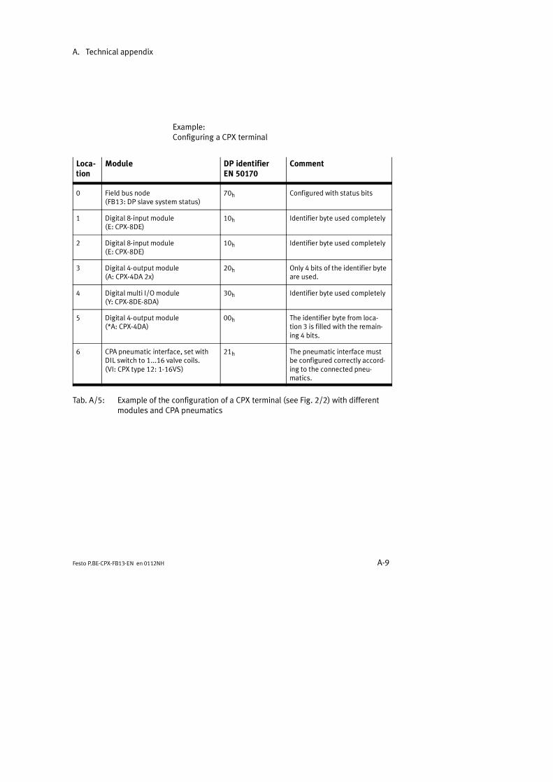
A. Technical appendix
A-9Festo P.BE-CPX-FB13-EN en 0112NH
Example:Configuring a CPX terminal
Loca-tion
Module DP identifierEN 50170
Comment
0 Field bus node(FB13: DP slave system status)
70h Configured with status bits
1 Digital 8-input module(E: CPX-8DE)
10h Identifier byte used completely
2 Digital 8-input module(E: CPX-8DE)
10h Identifier byte used completely
3 Digital 4-output module(A: CPX-4DA 2x)
20h Only 4 bits of the identifier byteare used.
4 Digital multi I/O module(Y: CPX-8DE-8DA)
30h Identifier byte used completely
5 Digital 4-output module(*A: CPX-4DA)
00h The identifier byte from loca-tion 3 is filled with the remain-ing 4 bits.
6 CPA pneumatic interface, set withDIL switch to 1...16 valve coils.(VI: CPX type 12: 1-16VS)
21h The pneumatic interface mustbe configured correctly accord-ing to the connected pneu-matics.
Tab. A/5: Example of the configuration of a CPX terminal (see Fig. 2/2) with differentmodules and CPA pneumatics

A. Technical appendix
A-10 Festo P.BE-CPX-FB13-EN en 0112NH
A.2.4 Error treatment
With the function Set_Prm you have the possibility of deter-mining the watchdog time (WD_Fact_1, Octet 2, WD_Fact_2,Octet 3).The reaction of the CPX terminal to a fault (e.g. bus failure)depends on the parametrizing. Further information can befound in chapter 3.6.
A.2.5 Request diagnostic information
Slave_Diag The diagnostic data are requested by the CPX terminal withthe function Slave_Diag. A description of this function can befound in section 3.5.3, Diagnosis via PROFIBUS-DP.
A.2.6 Start cyclic exchange of data
Data_Exchange The cyclic exchange of data is accomplished with the functionData_Exchange.With this function the output data for CPX terminals are trans-mitted as an octet string of length x. The octet string lengthdepends on the number of identifier bytes.
Please noteWith the function Data_Exchange, the CPX terminal ex-pects the output information for the valves and electricoutputs.
The input information is sent to the master as a replytelegram.
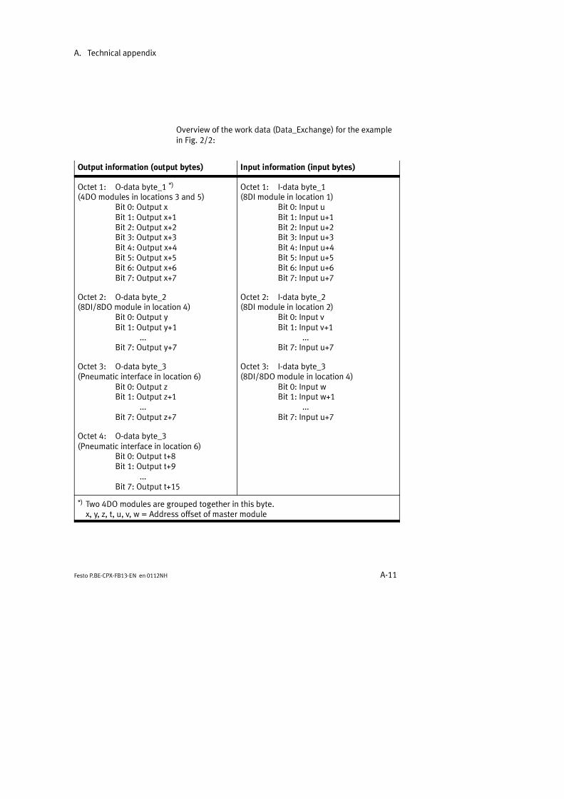
A. Technical appendix
A-11Festo P.BE-CPX-FB13-EN en 0112NH
Overview of the work data (Data_Exchange) for the examplein Fig. 2/2:
Output information (output bytes) Input information (input bytes)
Octet 1: O-data byte_1 *)
(4DO modules in locations 3 and 5)Bit 0: Output xBit 1: Output x+1Bit 2: Output x+2Bit 3: Output x+3Bit 4: Output x+4Bit 5: Output x+5Bit 6: Output x+6Bit 7: Output x+7
Octet 2: O-data byte_2(8DI/8DO module in location 4)
Bit 0: Output yBit 1: Output y+1
...Bit 7: Output y+7
Octet 3: O-data byte_3(Pneumatic interface in location 6)
Bit 0: Output zBit 1: Output z+1
...Bit 7: Output z+7
Octet 4: O-data byte_3(Pneumatic interface in location 6)
Bit 0: Output t+8Bit 1: Output t+9
...Bit 7: Output t+15
Octet 1: I-data byte_1(8DI module in location 1)
Bit 0: Input uBit 1: Input u+1Bit 2: Input u+2Bit 3: Input u+3Bit 4: Input u+4Bit 5: Input u+5Bit 6: Input u+6Bit 7: Input u+7
Octet 2: I-data byte_2(8DI module in location 2)
Bit 0: Input vBit 1: Input v+1
...Bit 7: Input u+7
Octet 3: I-data byte_3(8DI/8DO module in location 4)
Bit 0: Input wBit 1: Input w+1
...Bit 7: Input u+7
*) Two 4DO modules are grouped together in this byte.x, y, z, t, u, v, w = Address offset of master module

A. Technical appendix
A-12 Festo P.BE-CPX-FB13-EN en 0112NH
A.2.7 Implemented functions and service access points (SAP)
Function Available Destination SAP(DSAP)
Data_Exchange Yes NIL
RD_Inp Yes 56
RD_Outp Yes 57
Slave_Diag Yes 60
Set_Prm *) Yes 61
Chk_Cfg Yes 62
Get_Cfg Yes 59
Global_Control Yes 58
Set_Slave_Add No 55
MSAC_C1 Yes 50, 51
MSAC_C2 Yes 0...48
*) The CPX parameters are herewith also sent during the initiali-zation phase.
Tab. A/6: Overview of functions and service access points
You can access the DPV1 services with the following func-tions:
MSAC_C1: For masters of class 1 (e.g. PLC), fixedservice access points.
MSAC_C2: For masters of class 2 (e.g. PC/pro-grammer), dynamic use, service access points arespecified when connections are set up.
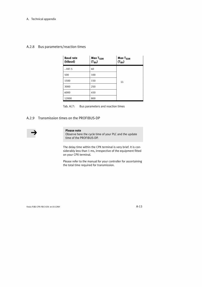
A. Technical appendix
A-13Festo P.BE-CPX-FB13-EN en 0112NH
A.2.8 Bus parameters/reaction times
Baud rate(kBaud)
Max TSDR(TBit)
Max TSDR(TBit)
..187.5 60
500 100
1500 150 11
3000 250
11
6000 450
12000 800
Tab. A/7: Bus parameters and reaction times
A.2.9 Transmission times on the PROFIBUS-DP
Please noteObserve here the cycle time of your PLC and the updatetime of the PROFIBUS-DP.
The delay time within the CPX terminal is very brief. It is con-siderably less than 1 ms, irrespective of the equipment fittedon your CPX terminal.
Please refer to the manual for your controller for ascertainingthe total time required for transmission.

A. Technical appendix
A-14 Festo P.BE-CPX-FB13-EN en 0112NH
A.3 Access to the CPX terminal via DPV1
By means of DPV1 commands you can access all the data andparameters which the CPX terminal provides:
Parameter and status information
System data
DPV1 commands are only available if you configure the fieldbus node as follows:
FB13: DP slave system diagnosis
You can easily access the system data by means of the PROFI-BUS configuration software. Background information can befound in the CPX system manual P.BE-CPX-SYS-.. .
A.3.1 Reading and writing data records
Use the function module SFC 59 for reading and SFC 58 forwriting data. First set the DPV1 compatibility S7-conform asfollows:
Set the DPV1 compatibility
Parametrize the field bus node S7-conform if you are workingwith a Siemens master:
1. Proceed as described in section 2.2.2, double-click in step1 but on the line of the field bus node in the configurationtable.The mask Properties DP slave appears.
2. Select the register Parameter Assignment and modifythe value of the DPV1-Services to S7 compatible(see following diagram).
3. Confirm with OK.
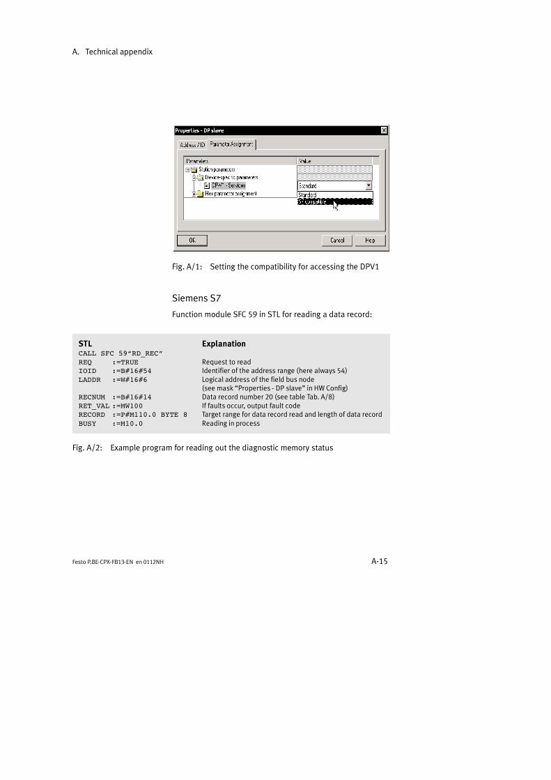
A. Technical appendix
A-15Festo P.BE-CPX-FB13-EN en 0112NH
Fig. A/1: Setting the compatibility for accessing the DPV1
Siemens S7
Function module SFC 59 in STL for reading a data record:
STL ExplanationCALL SFC 59RD_RECREQ :=TRUE Request to readIOID :=B#16#54 Identifier of the address range (here always 54)LADDR :=W#16#6 Logical address of the field bus node
(see mask Properties - DP slave in HW Config)RECNUM :=B#16#14 Data record number 20 (see table Tab. A/8)RET_VAL :=MW100 If faults occur, output fault codeRECORD :=P#M110.0 BYTE 8 Target range for data record read and length of data recordBUSY :=M10.0 Reading in process
Fig. A/2: Example program for reading out the diagnostic memory status
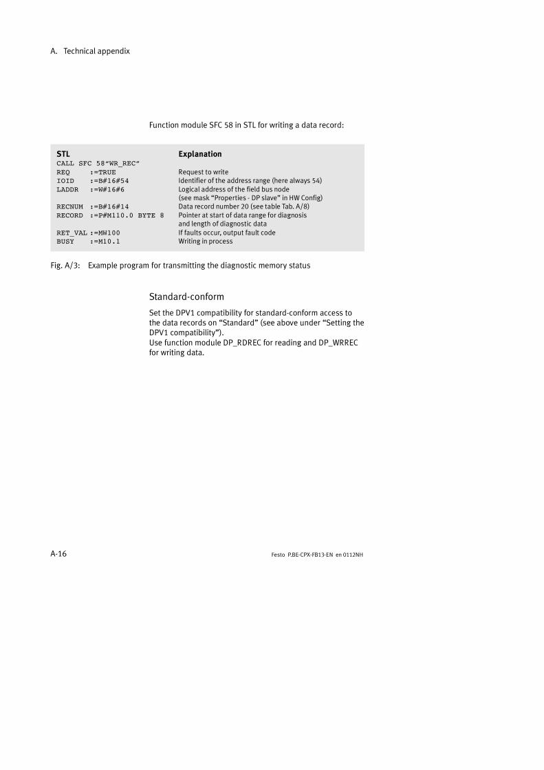
A. Technical appendix
A-16 Festo P.BE-CPX-FB13-EN en 0112NH
Function module SFC 58 in STL for writing a data record:
STL ExplanationCALL SFC 58WR_RECREQ :=TRUE Request to writeIOID :=B#16#54 Identifier of the address range (here always 54)LADDR :=W#16#6 Logical address of the field bus node
(see mask Properties - DP slave in HW Config)RECNUM :=B#16#14 Data record number 20 (see table Tab. A/8)RECORD :=P#M110.0 BYTE 8 Pointer at start of data range for diagnosis
and length of diagnostic dataRET_VAL :=MW100 If faults occur, output fault codeBUSY :=M10.1 Writing in process
Fig. A/3: Example program for transmitting the diagnostic memory status
Standard-conform
Set the DPV1 compatibility for standard-conform access tothe data records on Standard (see above under Setting theDPV1 compatibility).Use function module DP_RDREC for reading and DP_WRRECfor writing data.
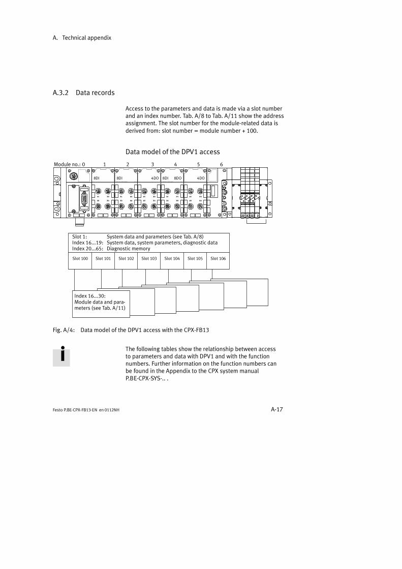
A. Technical appendix
A-17Festo P.BE-CPX-FB13-EN en 0112NH
A.3.2 Data records
Access to the parameters and data is made via a slot numberand an index number. Tab. A/8 to Tab. A/11 show the addressassignment. The slot number for the module-related data isderived from: slot number = module number + 100.
Data model of the DPV1 access
0 1 2 3 4 5 6
8DI 8DI 4DO 8DI 4DO
Module no.:
8DO
Slot 100 Slot 101 Slot 102 Slot 103 Slot 104 Slot 105 Slot 106
Slot 1: System data and parameters (see Tab. A/8)Index 16...19: System data, system parameters, diagnostic dataIndex 20...65: Diagnostic memory
Index 16...30:Module data and para-meters (see Tab. A/11)
Fig. A/4: Data model of the DPV1 access with the CPX-FB13
The following tables show the relationship between accessto parameters and data with DPV1 and with the functionnumbers. Further information on the function numbers canbe found in the Appendix to the CPX system manualP.BE-CPX-SYS-.. .
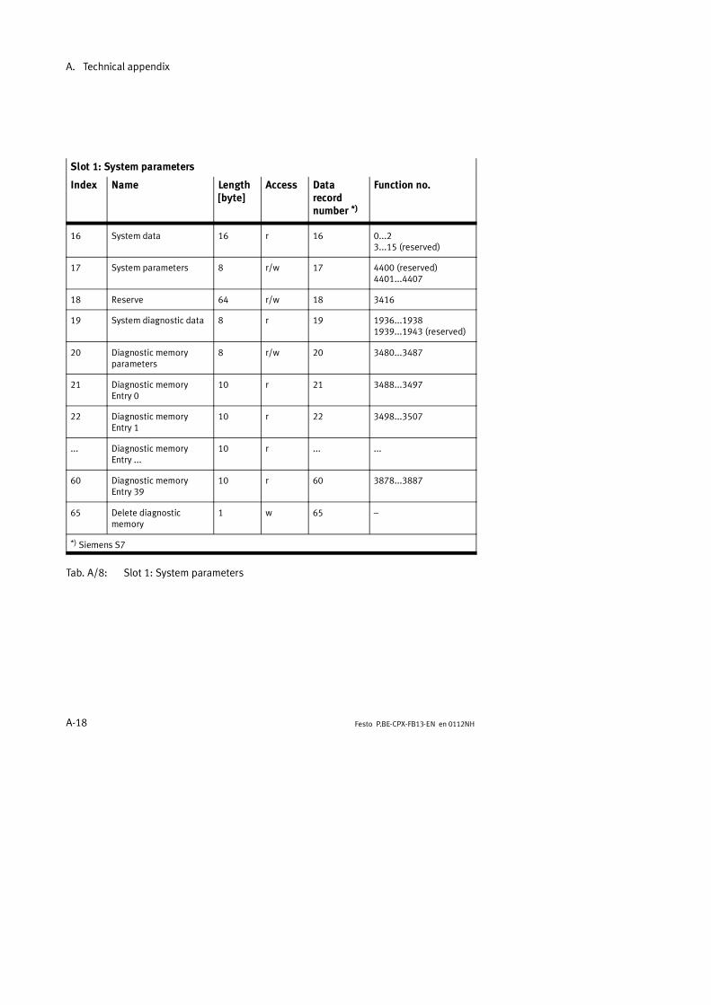
A. Technical appendix
A-18 Festo P.BE-CPX-FB13-EN en 0112NH
Slot 1: System parameters
Index Name Length[byte]
Access Datarecordnumber *)
Function no.
16 System data 16 r 16 0...23...15 (reserved)
17 System parameters 8 r/w 17 4400 (reserved)4401...4407
18 Reserve 64 r/w 18 3416
19 System diagnostic data 8 r 19 1936...19381939...1943 (reserved)
20 Diagnostic memoryparameters
8 r/w 20 3480...3487
21 Diagnostic memoryEntry 0
10 r 21 3488...3497
22 Diagnostic memoryEntry 1
10 r 22 3498...3507
... Diagnostic memoryEntry ...
10 r ... ...
60 Diagnostic memoryEntry 39
10 r 60 3878...3887
65 Delete diagnosticmemory
1 w 65
*) Siemens S7
Tab. A/8: Slot 1: System parameters

A. Technical appendix
A-19Festo P.BE-CPX-FB13-EN en 0112NH
Slot 2: Channel-specific module parameters
Index Name Length[byte]
Access Datarecordnumber *)
Function no.
16 Fault mode 64 r 2 3888
17 Fault state 64 r 3 3952
18 Force mode outputs 64 r 4 4016
19 Force state outputs 64 r 5 4080
20 Force mode inputs 64 r 6 4144
21 Force state inputs 64 r 7 4208
22 Global operating systemdata
40 r 8 4792
Tab. A/9: Slot 2: Channel-specific module parameters
With slot 3 you have indirect reading and writing access tothe data records (System parameters, Module data andModule parameters). To do this, assign the 4 bytes of thecommand box with: the slot number, the index number andan offset (byte 4 is reserved). With the read box and the writebox you can then carry out the read or write process.
Slot 3: Indexed addressing of the objects
Index Name Length[byte]
Access Datarecordnumber *)
Function no.
16 Command box 4 r/w 9
17 Read box 64 r 10
18 Write box 64 w 11
*) Siemens S7
Tab. A/10: Slot 3: Indexed addressing of the objects
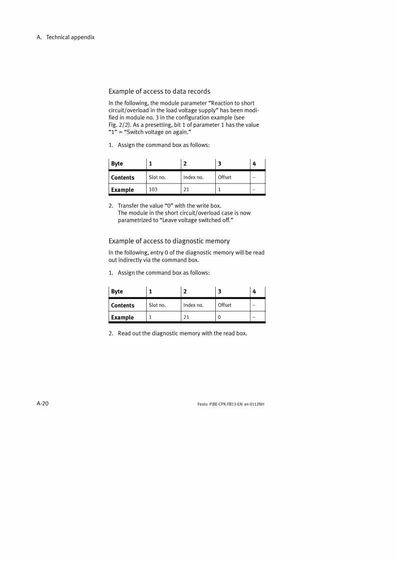
A. Technical appendix
A-20 Festo P.BE-CPX-FB13-EN en 0112NH
Example of access to data records
In the following, the module parameter Reaction to shortcircuit/overload in the load voltage supply has been modi-fied in module no. 3 in the configuration example (seeFig. 2/2). As a presetting, bit 1 of parameter 1 has the value1 = Switch voltage on again.
1. Assign the command box as follows:
Byte 1 2 3 4
Contents Slot no. Index no. Offset
Example 103 21 1
2. Transfer the value 0 with the write box.The module in the short circuit/overload case is nowparametrized to Leave voltage switched off.
Example of access to diagnostic memory
In the following, entry 0 of the diagnostic memory will be readout indirectly via the command box.
1. Assign the command box as follows:
Byte 1 2 3 4
Contents Slot no. Index no. Offset
Example 1 21 0
2. Read out the diagnostic memory with the read box.
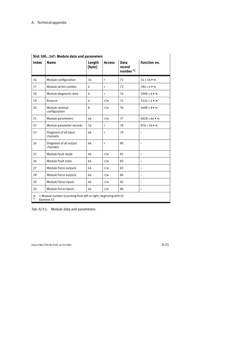
A. Technical appendix
A-21Festo P.BE-CPX-FB13-EN en 0112NH
Slot 100...147: Module data and parameters
Index Name Length[byte]
Access Datarecordnumber *)
Function no.
16 Module configuration 16 r 72 16 + 16 m
17 Module series number 4 r 73 784 + 4 m
18 Module diagnostic data 4 r 74 2008 + 4 m
19 Reserve 4 r/w 75 3224 + 4 m
20 Module nominalconfiguration
8 r/w 76 4408 + 8 m
21 Module parameters 64 r/w 77 4828 + 64 m
22 Module parameter records 16 r 78 976 + 16 m
23 Diagnosis of all inputchannels
64 r 79
24 Diagnosis of all outputchannels
64 r 80
25 Module Fault mode 64 r/w 81
26 Module Fault state 64 r/w 82
27 Module Force outputs 64 r/w 83
28 Module Force outputs 64 r/w 84
29 Module Force inputs 64 r/w 85
30 Module Force inputs 64 r/w 86
m =Module number (counting from left to right, beginning with 0)*) Siemens S7
Tab. A/11: Module data and parameters

A. Technical appendix
A-22 Festo P.BE-CPX-FB13-EN en 0112NH

Index
B-1Festo P.BE-CPX-FB13-EN en 0112NH
Appendix B

B. Index
B-2 Festo P.BE-CPX-FB13-EN en 0112NH
Contents
B. Index B-1. . . . . . . . . . . . . . . . . . . . . . . . . . . . . . . . . . . . . . . . . . . . . . . . . . . . . . . . .

B. Index
B-3Festo P.BE-CPX-FB13-EN en 0112NH
B.1 Index
A
AbbreviationsProduct-specific XI. . . . . . . . . . . . . . . . . . . . . . . . . . . . . . . . .
Additional supply 1-27. . . . . . . . . . . . . . . . . . . . . . . . . . . . . . . .
Addressing 2-5. . . . . . . . . . . . . . . . . . . . . . . . . . . . . . . . . . . . . .COM PROFIBUS 2-17. . . . . . . . . . . . . . . . . . . . . . . . . . . . . . .STEP 7 2-22. . . . . . . . . . . . . . . . . . . . . . . . . . . . . . . . . . . . . . .
B
Baud rate 1-19. . . . . . . . . . . . . . . . . . . . . . . . . . . . . . . . . . . . . .
BF LED 3-7. . . . . . . . . . . . . . . . . . . . . . . . . . . . . . . . . . . . . . . . . .
Branch line lengths 1-19. . . . . . . . . . . . . . . . . . . . . . . . . . . . . .
Bus termination 1-23. . . . . . . . . . . . . . . . . . . . . . . . . . . . . . . . .
C
CablesField bus 1-18. . . . . . . . . . . . . . . . . . . . . . . . . . . . . . . . . . . . .
CLEAR_DATA 2-5. . . . . . . . . . . . . . . . . . . . . . . . . . . . . . . . . . . . .
COM PROFIBUS 5.0 2-12. . . . . . . . . . . . . . . . . . . . . . . . . . . . . .
Configuration 2-4. . . . . . . . . . . . . . . . . . . . . . . . . . . . . . . . . . . .With Siemens master 2-12. . . . . . . . . . . . . . . . . . . . . . . . . . .
ConnectingField bus 1-18, 1-20. . . . . . . . . . . . . . . . . . . . . . . . . . . . . . . .Power supply 1-26. . . . . . . . . . . . . . . . . . . . . . . . . . . . . . . . .
Cyclic exchange of data A-10. . . . . . . . . . . . . . . . . . . . . . . . . . .
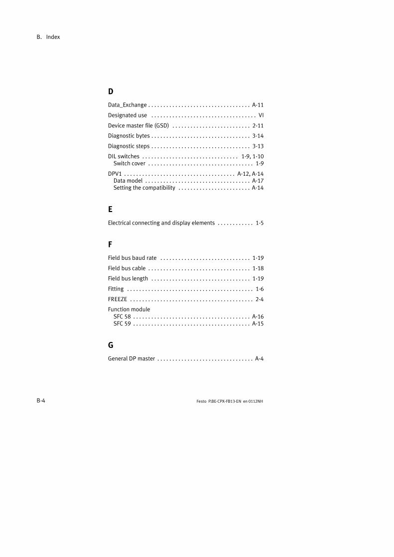
B. Index
B-4 Festo P.BE-CPX-FB13-EN en 0112NH
D
Data_Exchange A-11. . . . . . . . . . . . . . . . . . . . . . . . . . . . . . . . . .
Designated use VI. . . . . . . . . . . . . . . . . . . . . . . . . . . . . . . . . . .
Device master file (GSD) 2-11. . . . . . . . . . . . . . . . . . . . . . . . . .
Diagnostic bytes 3-14. . . . . . . . . . . . . . . . . . . . . . . . . . . . . . . . .
Diagnostic steps 3-13. . . . . . . . . . . . . . . . . . . . . . . . . . . . . . . . .
DIL switches 1-9, 1-10. . . . . . . . . . . . . . . . . . . . . . . . . . . . . . . .Switch cover 1-9. . . . . . . . . . . . . . . . . . . . . . . . . . . . . . . . . . .
DPV1 A-12, A-14. . . . . . . . . . . . . . . . . . . . . . . . . . . . . . . . . . . . .Data model A-17. . . . . . . . . . . . . . . . . . . . . . . . . . . . . . . . . . .Setting the compatibility A-14. . . . . . . . . . . . . . . . . . . . . . . .
E
Electrical connecting and display elements 1-5. . . . . . . . . . . .
F
Field bus baud rate 1-19. . . . . . . . . . . . . . . . . . . . . . . . . . . . . .
Field bus cable 1-18. . . . . . . . . . . . . . . . . . . . . . . . . . . . . . . . . .
Field bus length 1-19. . . . . . . . . . . . . . . . . . . . . . . . . . . . . . . . .
Fitting 1-6. . . . . . . . . . . . . . . . . . . . . . . . . . . . . . . . . . . . . . . . . .
FREEZE 2-4. . . . . . . . . . . . . . . . . . . . . . . . . . . . . . . . . . . . . . . . .
Function moduleSFC 58 A-16. . . . . . . . . . . . . . . . . . . . . . . . . . . . . . . . . . . . . . .SFC 59 A-15. . . . . . . . . . . . . . . . . . . . . . . . . . . . . . . . . . . . . . .
G
General DP master A-4. . . . . . . . . . . . . . . . . . . . . . . . . . . . . . . .

B. Index
B-5Festo P.BE-CPX-FB13-EN en 0112NH
I
IdentifierGroupable 2-7. . . . . . . . . . . . . . . . . . . . . . . . . . . . . . . . . . . . .
Identifiers can be grouped together 2-7. . . . . . . . . . . . . . . . . .
Implemented functions (SAP) A-12. . . . . . . . . . . . . . . . . . . . . .
Important user instructions VIII. . . . . . . . . . . . . . . . . . . . . . . . .
L
LEDs 2-32, 3-6. . . . . . . . . . . . . . . . . . . . . . . . . . . . . . . . . . . . . .
M
Module data and parameters A-21. . . . . . . . . . . . . . . . . . . . . .
Module parameters 2-29. . . . . . . . . . . . . . . . . . . . . . . . . . . . . .
N
Notes on the use of this manual VII. . . . . . . . . . . . . . . . . . . . .
O
Optical-fibre waveguide 1-25. . . . . . . . . . . . . . . . . . . . . . . . . . .
P
ParametrizingApplication example 2-30. . . . . . . . . . . . . . . . . . . . . . . . . . . .Diagnostic memory 2-27. . . . . . . . . . . . . . . . . . . . . . . . . . . .Module parameters 2-29. . . . . . . . . . . . . . . . . . . . . . . . . . . .Start parametrizing 2-25. . . . . . . . . . . . . . . . . . . . . . . . . . . .System parameters 2-26. . . . . . . . . . . . . . . . . . . . . . . . . . . .

B. Index
B-6 Festo P.BE-CPX-FB13-EN en 0112NH
PELV 1-26. . . . . . . . . . . . . . . . . . . . . . . . . . . . . . . . . . . . . . . . . .
Pictograms IX. . . . . . . . . . . . . . . . . . . . . . . . . . . . . . . . . . . . . . .
Pin assignmentField bus interface 1-20. . . . . . . . . . . . . . . . . . . . . . . . . . . . .
Power supply 1-26. . . . . . . . . . . . . . . . . . . . . . . . . . . . . . . . . . .
RReaction times A-13. . . . . . . . . . . . . . . . . . . . . . . . . . . . . . . . . .
Removing 1-6. . . . . . . . . . . . . . . . . . . . . . . . . . . . . . . . . . . . . . .
SScreening/shield connection 1-21. . . . . . . . . . . . . . . . . . . . . . .
Send configuration data A-7. . . . . . . . . . . . . . . . . . . . . . . . . . .
Send parametrizing data A-5. . . . . . . . . . . . . . . . . . . . . . . . . . .
Service VII. . . . . . . . . . . . . . . . . . . . . . . . . . . . . . . . . . . . . . . . .
Service access points (SAP) A-12. . . . . . . . . . . . . . . . . . . . . . .
SettingDiagnostic mode 1-11. . . . . . . . . . . . . . . . . . . . . . . . . . . . . . .Station number 1-12. . . . . . . . . . . . . . . . . . . . . . . . . . . . . . . .
Station numbersPermitted 1-12. . . . . . . . . . . . . . . . . . . . . . . . . . . . . . . . . . . .Setting 1-13. . . . . . . . . . . . . . . . . . . . . . . . . . . . . . . . . . . . . . .
Station status 3-18. . . . . . . . . . . . . . . . . . . . . . . . . . . . . . . . . . .
STEP 7 online diagnosis 3-27. . . . . . . . . . . . . . . . . . . . . . . . . . .
STEP 7 V5.1 - Hardware configurator 2-18. . . . . . . . . . . . . . . .
Strain relief 1-20. . . . . . . . . . . . . . . . . . . . . . . . . . . . . . . . . . . . .
Sub-D plugs from Festo 1-21. . . . . . . . . . . . . . . . . . . . . . . . . . .
Switch coverFitting and removing 1-8. . . . . . . . . . . . . . . . . . . . . . . . . . . .
Symbol files 2-11. . . . . . . . . . . . . . . . . . . . . . . . . . . . . . . . . . . .
SYNC 2-5. . . . . . . . . . . . . . . . . . . . . . . . . . . . . . . . . . . . . . . . . . .
System supply 1-27. . . . . . . . . . . . . . . . . . . . . . . . . . . . . . . . . .

B. Index
B-7Festo P.BE-CPX-FB13-EN en 0112NH
T
Target group VII. . . . . . . . . . . . . . . . . . . . . . . . . . . . . . . . . . . . .
Technical specifications A-3. . . . . . . . . . . . . . . . . . . . . . . . . . . .
Text markings IX. . . . . . . . . . . . . . . . . . . . . . . . . . . . . . . . . . . . .
W
Work data A-11. . . . . . . . . . . . . . . . . . . . . . . . . . . . . . . . . . . . . .

B. Index
B-8 Festo P.BE-CPX-FB13-EN en 0112NH