
ELEC 5270/6270 Spring 2013 Low-Power Design of Electronic Circuits Tools for Power Analysis...
31
ELEC 5270/6270 Spring 2013 Low-Power Design of Electronic Circuits Tools for Power Analysis http://www.eng.auburn.edu/~vagrawal/COURSE/E6270_Spr13/cours e.html Murali Dharan January 9, 2013 1
-
Upload
brett-green -
Category
Documents
-
view
215 -
download
2
Transcript of ELEC 5270/6270 Spring 2013 Low-Power Design of Electronic Circuits Tools for Power Analysis...

ELEC 5270/6270 Spring 2013Low-Power Design of Electronic Circuits
Tools for Power Analysishttp://www.eng.auburn.edu/~vagrawal/COURSE/E6270_Spr13/course.html
Murali DharanJanuary 9, 2013
1

Course Objectives
Understand the need for low power in VLSI design.
Learn basic ideas, concepts, theory and methods.
Get experience with tools and techniques.
2

Low-Power Design Methods
Algorithms and architectures
High-level and software techniques
Gate and circuit-level methods
Test Power3

VLSI Simulation and Synthesis Tools
QuestaSim Designing, compiling and simulating designs
LeonardoSpectrum ASIC and standard cell synthesis
DesignArchitect-IC Schematic Capture
HSPICE Circuit simulation and verification
4

Some Power Analysis Tools and Techniques
PowerPlay Logic simulation based power estimator
PrimeTime PX Early stage power estimator
NanoSim Analog Circuit Engine (ACE) simulator
HSPICE SPICE Engine simulator (Industry standard)
5

EDA Tools Setup
Download sample.bashrc file from Dr. Nelson's website.
Rename file to .bashrc and save it on your home directory.
http://www.eng.auburn.edu/~nelson/courses/elec5250_6250/bashrc
6
QuestaSim
Invoked using the command “vsim” at the shell prompt
Create HDL models (behavioral/structural) Can verify functionality using simulations Supports VHDL, Verilog, SystemC,
SystemVerilog
7

QuestaSim
8

QuestaSim Simulation Steps
After writing your HDL code, you should compile it to check for errors and/or inconsistencies.
If no errors are there, the compiled code will be available in your “work” library.
To run the simulation, you can double click the module in the “work” library.
9

10

LeonardoSpectrum Synthesis Steps
Load technology library in the database Load the HDL file in the database Specify design constraints (timing, area) Compile/optimize design Generate technology specific HDL netlists Generate reports (area, timing)
11

Synthesis Steps
Execute “spectrum -file filename.tcl” at the shell prompt.
Tcl file contains the list of spectrum commands which are executed sequentially.
12

Load Library
load_library /linux_apps/ADK3.1/technology/leonardo/tsmc035_typ
Available ADK libraries: tsmc035_typ (use this for projects) tsmc025_typ tsmc018_typ ami12_typ ami05_typ
13

Read HDL File
read {file1.vhd folder/file2.vhd “file 3.vhd”} -format VHDL (or verilog)
Syntax check and builds database (analyze) Synthesize generic gates and black boxes
(elaborate) Technology independent logic optimization
(pre_optimize)14

Optimize Design
optimize <design> (default is current design)
Various switches can change the functionality of the command
-effort quick (one pass) or standard (multiple passes)
-area, -delay, -auto (default) -hierarchy preserve, flatten or auto (default)
15

Save Design to File
write <filename>
-silent (no warnings or messages) -format <format name>
Verilog (.v) VHDL (.vhd) SDF (.sdf) EDIF (.edf)
16

Area Report
report_area [<filename>]
-cell_usage -hierarchy -all_leafs
17
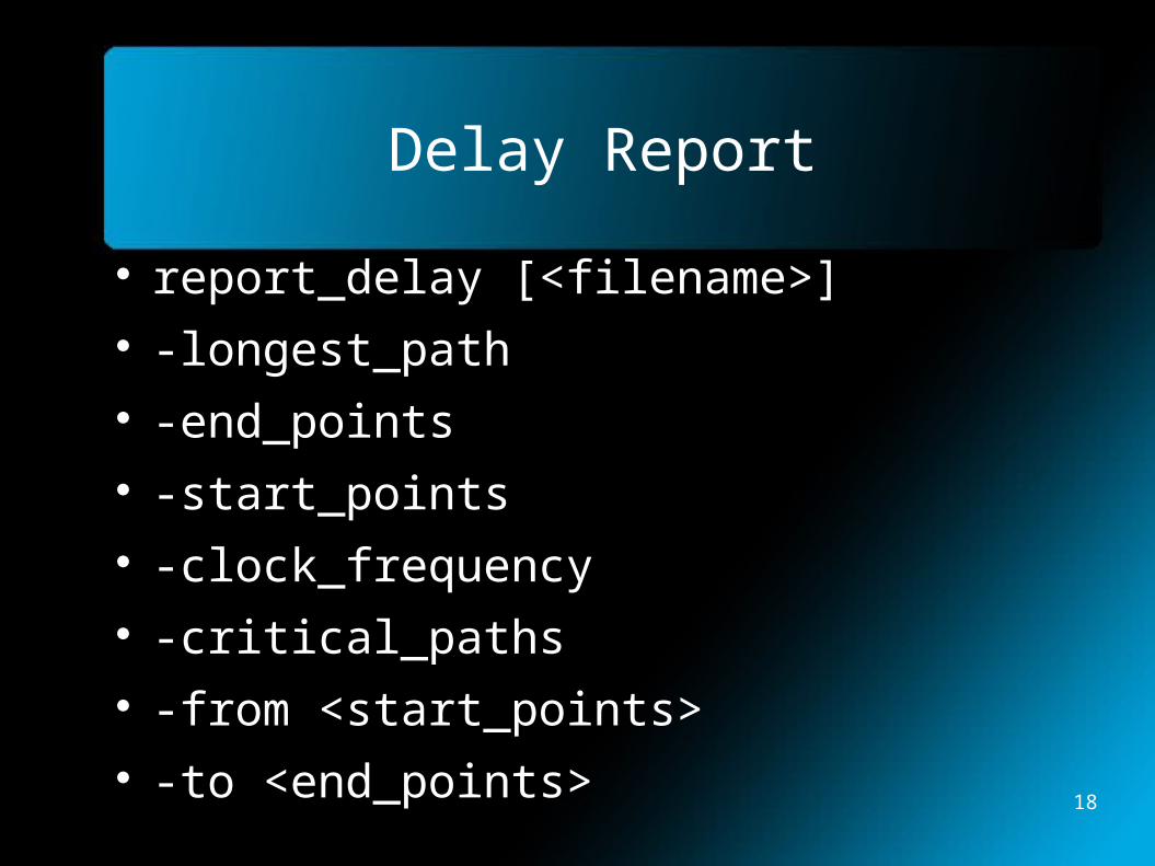
Delay Report
report_delay [<filename>] -longest_path -end_points -start_points -clock_frequency -critical_paths -from <start_points> -to <end_points> 18
Spectrum Documentation
In shell prompt, type mgcdocs $LEO_DOCS
User's Manual Reference Manual HDL Synthesis Manual Synthesis and Technology Manual
19
DesignArchitect-IC
Invoked using the command “adk_daic” at the shell prompt.
Loads the ADK libraries set up at the .bashrc file.
Import the newly synthesized verilog netlist Go to File -> Import Verilog
Mapping file $ADK/technology/adk_map.vmp
20
DesignArchitect-IC
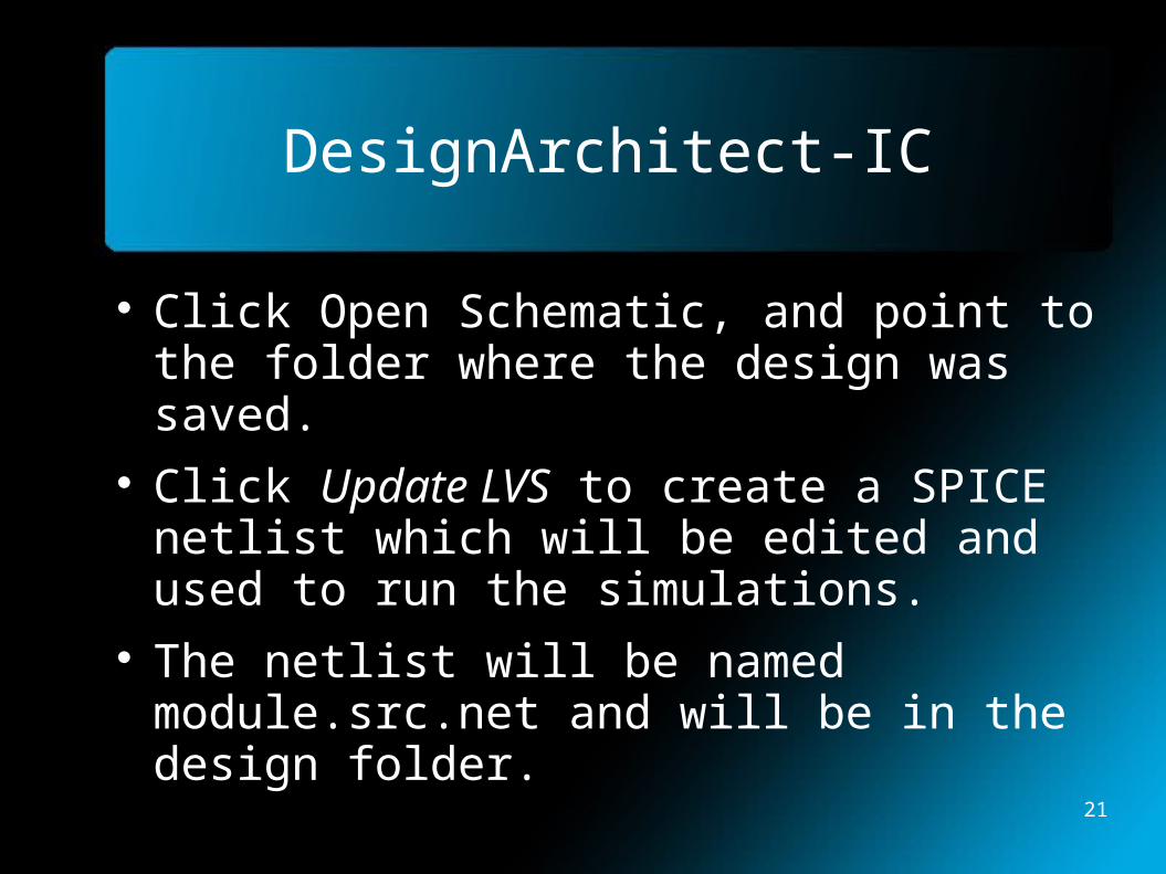
Click Open Schematic, and point to the folder where the design was saved.
Click Update LVS to create a SPICE netlist which will be edited and used to run the simulations.
The netlist will be named module.src.net and will be in the design folder.
21

SPICE Netlist Modifications
The length and width parameters need to be changed while keeping the ratios constant.
Change the L value to match the technology file specifications.
Change the W values w.r.t the L values such that the previous ratios are maintained.
Include the transistor technology fileshttp://ptm.asu.edu
22

SPICE Netlist Modifications
A top level module needs to be created which instantiates the primary inputs and outputs.
X_modulename signal1 signal2... modulename
.end command is added at the end of the netlist which shows the end of SPICE netlist.
23

Useful SPICE Commands
.inc <filename> .option post brief probe
Post stores simulation results for analysis Brief doesn't print data file till .end
statement Probe limits output to .probe, .print, .plot,
and .graph statements .param <parameter value>
24

SPICE Data Statements
Independent DC Sources Vname N1 N2 Type Value Iname N1 N2 Type Value
N1 is the positive terminal N2 is the negative terminal Type can be DC, AC or TRAN Value is the value of the source Names should prefix with V or I
25

SPICE Data Statements
Dependent DC Sources Vname N1 N2 PWL (T1 V1 T2 V2 ...) Vname N1 N2 PULSE (V1 V2 Td Tr Tf PW
Period) Td – initial delay time Tr – rise time Tf – fall time PW – pulse width
26
SPICE Data Statements
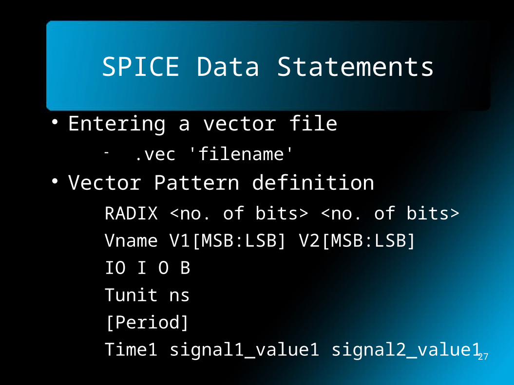
Entering a vector file .vec 'filename'
Vector Pattern definition
RADIX <no. of bits> <no. of bits>
Vname V1[MSB:LSB] V2[MSB:LSB]
IO I O B
Tunit ns
[Period]
Time1 signal1_value1 signal2_value1 27
SPICE Data Analysis
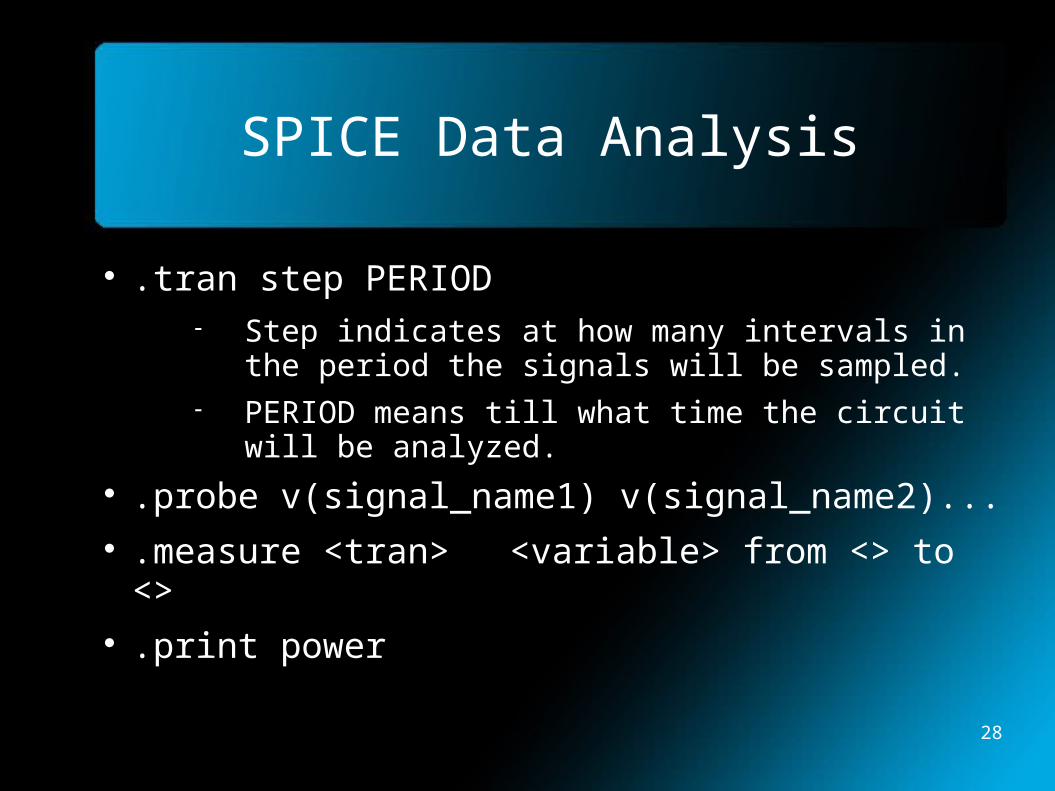
.tran step PERIOD Step indicates at how many intervals in the
period the signals will be sampled. PERIOD means till what time the circuit will
be analyzed. .probe v(signal_name1) v(signal_name2)... .measure <tran> <variable> from <> to <> .print power
28

SPICE Simulations and Analysis
HSPICE invoked by writing “hspice” in the shell prompt.
Opens up a xterm window, then hspice is invoked for a specific netlist.
hspice -i inputfile.sp > output.out Waveform viewer invoked using the
command “ezwave” from the shell prompt. Used to view the waveforms of the probed
signals after the SPICE simulations.29

NanoSim
Invoked with “nsim” command at shell prompt, then typing “nanosimgui” at the xterm window.
Uses the same SPICE netlist used in HSPICE.
HSPICE more accurate, but NanoSim faster for larger circuits.
30

References
Dr. Nelson's CAD Tools course http://www.eng.auburn.edu/~nelson/courses/elec5250_6250/
HSPICE Reference Manual NanoSim Reference Manual Predictive Technology Model website
http://ptm.asu.edu
31