
Design Guide VLT® AutomationDrive FC 361 90–315 kW ...
102
ENGINEERING TOMORROW Design Guide VLT® AutomationDrive FC 361 90–315 kW, Enclosure Sizes J8–J9 vlt-drives.danfoss.com
Transcript of Design Guide VLT® AutomationDrive FC 361 90–315 kW ...
ENGINEERING TOMORROW
Design GuideVLT® AutomationDrive FC 36190–315 kW, Enclosure Sizes J8–J9
vlt-drives.danfoss.com

Contents
1 Introduction 4
1.1 Purpose of the Design Guide 4
1.2 Additional Resources 4
1.3 Document and Software Version 4
1.4 Approvals and Certifications 4
1.5 Conventions 5
2 Safety 6
2.1 Safety Symbols 6
2.2 Qualified Personnel 6
2.3 Safety Precautions 6
3 Product Overview and Features 7
3.1 Power Ratings, Weights, and Dimensions 7
3.2 Automated Operational Features 8
3.3 Custom Application Features 10
3.4 Dynamic Braking Overview 13
3.5 Back-channel Cooling Overview 14
4 Options and Accessories Overview 15
4.1 Fieldbus Devices 15
4.2 Functional Extensions 15
5 Specifications 16
5.1 Electrical Data, 380-480 V 16
5.2 Mains Supply 18
5.3 Motor Output and Motor Data 18
5.4 Ambient Conditions 18
5.5 Cable Specifications 19
5.6 Control Input/Output and Control Data 19
5.7 Enclosure Weights 22
5.8 Exterior and Terminal Dimensions 23
6 Mechanical Installation Considerations 33
6.1 Storage 33
6.2 Lifting the Unit 33
6.3 Operating Environment 34
6.4 Mounting Configurations 34
6.5 Cooling 35
6.6 Derating 35
Contents Design Guide
MG06K102 Danfoss A/S © 03/2019 All rights reserved. 1

7 Electrical Installation Considerations 38
7.1 Safety Instructions 38
7.2 Wiring Schematic 39
7.3 Connections 40
7.4 Control Wiring and Terminals 41
7.5 Fuses and Circuit Breakers 44
7.6 Motor 45
7.7 Residual Current Devices (RCD) and Insulation Resistance Monitor (IRM) 47
7.8 Leakage Current 47
7.9 IT Mains 49
7.10 Efficiency 49
7.11 Acoustic Noise 49
7.12 dU/dt Conditions 50
7.13 Electromagnetic Compatibility (EMC) Overview 51
7.14 EMC-compliant Installation 54
7.15 Harmonics Overview 57
8 Basic Operating Principles of a Drive 60
8.1 Description of Operation 60
8.2 Drive Controls 60
9 Application Examples 68
9.1 Programming a Closed-loop Drive System 68
9.2 Wiring for Open-loop Speed Control 68
9.3 Wiring for Start/Stop 69
9.4 Wiring for External Alarm Reset 70
9.5 Wiring for a Motor Thermistor 71
9.6 Wiring Configuration for the Encoder 71
10 How to Order a Drive 72
10.1 Drive Configurator 72
10.2 Ordering Numbers for Options and Accessories 74
10.3 Spare Parts 74
11 Appendix 75
11.1 Abbreviations and Symbols 75
11.2 Definitions 76
11.3 RS485 Installation and Set-up 77
11.4 RS485: FC Protocol Overview 78
11.5 RS485: FC Protocol Telegram Structure 79
11.6 RS485: FC Protocol Parameter Examples 83
Contents VLT® AutomationDrive FC 361
2 Danfoss A/S © 03/2019 All rights reserved. MG06K102

11.7 RS485: Modbus RTU Overview 83
11.8 RS485: Modbus RTU Telegram Structure 84
11.9 RS485: Modbus RTU Message Function Codes 87
11.10 RS485: Modbus RTU Parameters 88
11.11 RS485: FC Control Profile 88
Index 95
Contents Design Guide
MG06K102 Danfoss A/S © 03/2019 All rights reserved. 3
1 Introduction
1.1 Purpose of the Design Guide
This design guide is intended for:• Project and systems engineers.
• Design consultants.
• Application and product specialists.
The design guide provides technical information tounderstand the capabilities of the drive for integration intomotor control and monitoring systems.
VLT® is a registered trademark.
1.2 Additional Resources
Other resources are available to understand advanceddrive functions and programming.
• The operating guide provides detailed informationfor the installation and start-up of the drive.
• The programming guide provides greater detail onworking with parameters and many applicationexamples.
• Instructions for operation with optionalequipment.
Supplementary publications and manuals are availablefrom Danfoss. See www.danfoss.com/en/search/?filter=type%3Adocumentation%2Csegment%3Adds for listings.
1.3 Document and Software Version
This manual is regularly reviewed and updated. Allsuggestions for improvement are welcome. Table 1.1 showsthe version of the manual and the corresponding softwareversion.
Manual version Remarks Software version
MG06K1xx First edition. 1.0x
Table 1.1 Manual and Software Version
1.4 Approvals and Certifications
Drives are designed in compliance with the directivesdescribed in this section.
1.4.1 CE Mark
The CE mark (Conformité Européenne) indicates that theproduct manufacturer conforms to all applicable EUdirectives.
The EU directives applicable to the design andmanufacture of drives are:
• The Low Voltage Directive.
• The EMC Directive.
• The Machinery Directive (for units with anintegrated safety function).
The CE mark is intended to eliminate technical barriers tofree trade between the EC and EFTA states inside the ECU.The CE mark does not regulate the quality of the product.Technical specifications cannot be deduced from the CEmark.
1.4.2 Low Voltage Directive
Drives are classified as electronic components and must beCE-labeled in accordance with the Low Voltage Directive.The directive applies to all electrical equipment in the 50–1000 V AC and the 75–1500 V DC voltage ranges.
The directive mandates that the equipment design mustensure the safety and health of people and livestock, andthe preservation of material by ensuring the equipment isproperly installed, maintained, and used as intended.Danfoss CE labels comply with the Low Voltage Directive,and Danfoss provides a declaration of conformity uponrequest.
Introduction VLT® AutomationDrive FC 361
4 Danfoss A/S © 03/2019 All rights reserved. MG06K102
11
1.4.3 EMC Directive
Electromagnetic compatibility (EMC) means that electro-magnetic interference between pieces of equipment doesnot hinder their performance. The basic protectionrequirement of the EMC Directive 2014/30/EU states thatdevices that generate electromagnetic interference (EMI) orwhose operation could be affected by EMI must bedesigned to limit the generation of electromagneticinterference and shall have a suitable degree of immunityto EMI when properly installed, maintained, and used asintended.
A drive can be used as stand-alone device or as part of amore complex installation. Devices in either of these casesmust bear the CE mark. Systems must not be CE-markedbut must comply with the basic protection requirements ofthe EMC directive.
1.5 Conventions
• Numbered lists indicate procedures.
• Bullet lists indicate other information anddescription of illustrations.
• Italicized text indicates:
- Cross-reference.
- Link.
- Footnote.
- Parameter name, parameter groupname, parameter option.
• All dimensions in drawings are in mm (in).
• An asterisk (*) indicates a default setting of aparameter.
Introduction Design Guide
MG06K102 Danfoss A/S © 03/2019 All rights reserved. 5
1 1
2 Safety
2.1 Safety Symbols
The following symbols are used in this guide:
WARNINGIndicates a potentially hazardous situation that couldresult in death or serious injury.
CAUTIONIndicates a potentially hazardous situation that couldresult in minor or moderate injury. It can also be used toalert against unsafe practices.
NOTICEIndicates important information, including situations thatcan result in damage to equipment or property.
2.2 Qualified Personnel
Only qualified personnel are allowed to install or operatethis equipment.
Qualified personnel are defined as trained staff, who areauthorized to install, commission, and maintain equipment,systems, and circuits in accordance with pertinent laws andregulations. Also, the personnel must be familiar with theinstructions and safety measures described in this manual.
2.3 Safety Precautions
WARNINGHIGH VOLTAGEDrives contain high voltage when connected to AC mainsinput, DC supply, load sharing, or permanent motors.Failure to use qualified personnel to install, start up, andmaintain the drive can result in death or serious injury.
• Only qualified personnel must install, start up,and maintain the drive.
WARNINGDISCHARGE TIMEThe drive contains DC-link capacitors, which can remaincharged even when the drive is not powered. Highvoltage can be present even when the warning LEDindicator lights are off. Failure to wait the specified timeafter power has been removed before performing serviceor repair work can result in death or serious injury.
• Stop the motor.
• Disconnect AC mains and remote DC-link powersupplies, including battery back-ups, UPS, andDC-link connections to other drives.
• Disconnect or lock PM motor.
• Wait for the capacitors to discharge fully. Theminimum waiting time is 20 minutes.
• Before performing any service or repair work,use an appropriate voltage measuring device tomake sure that the capacitors are fullydischarged.
WARNINGLEAKAGE CURRENT HAZARDLeakage currents exceed 3.5 mA. Failure to ground thedrive properly can result in death or serious injury.
• Ensure the correct grounding of the equipmentby a certified electrical installer.
Safety VLT® AutomationDrive FC 361
6 Danfoss A/S © 03/2019 All rights reserved. MG06K102
22

3 Product Overview and Features
3.1 Power Ratings, Weights, and Dimensions
For enclosure sizes and power ratings of the drives, refer to Table 3.1. For more dimensions, see chapter 5.8 Exterior andTerminal Dimensions.
Enclosure size J8 J9
IPNEMA
20Chassis
20Chassis
Shipping dimensions [mm (in)] Height 587 (23) 587 (23)
Width 997 (39) 1170 (46)
Depth 460 (18) 535 (21)
Drive dimensions [mm (in)]
Height 909 (36) 1122 (44)
Width 250 (10) 350 (14)
Depth 375 (15) 375 (15)
Maximum weight [kg (lb)] 98 (216) 164 (362)
Table 3.1 Power Ratings, Weight, and Dimensions, Enclosure Sizes J8–J9, 380–480 V
Product Overview and Featur... Design Guide
MG06K102 Danfoss A/S © 03/2019 All rights reserved. 7
3 3

3.2 Automated Operational Features
Automated operational features are active when the driveis operating. Most of them require no programming or set-up. The drive has a range of built-in protection functionsto protect itself and the motor when it runs.
For details of any set-up required, in particular motorparameters, refer to the programming guide.
3.2.1 Short-circuit Protection
Motor (phase-to-phase)The drive is protected against short circuits on the motorside by current measurement in each of the 3 motorphases. A short circuit between 2 output phases causes anovercurrent in the inverter. The inverter is turned off whenthe short circuit current exceeds the allowed value (Alarm16, Trip Lock).
Mains sideA drive that works correctly limits the current it can drawfrom the supply. Still, it is recommended to use fusesand/or circuit breakers on the supply side as protection ifthere is component break-down inside the drive (1st fault).
NOTICETo ensure compliance with IEC 60364 for CE, it ismandatory to use fuses and/or circuit breakers.
3.2.2 Overvoltage Protection
Motor-generated overvoltageThe voltage in the DC link is increased when the motoracts as a generator. This situation occurs in the followingcases:
• The load rotates the motor at constant outputfrequency from the drive, that is, the loadgenerates energy.
• During deceleration (ramp-down) if the inertiamoment is high, the friction is low, and the ramp-down time is too short for the energy to bedissipated as a loss throughout the drive system.
• Incorrect slip compensation setting causinghigher DC-link voltage.
• Back EMF from PM motor operation. If coasted athigh RPM, the PM motor back EMF canpotentially exceed the maximum voltagetolerance of the drive and cause damage. To helpprevent this situation, the value ofparameter 4-19 Max Output Frequency is automat-ically limited based on an internal calculationbased on the value of parameter 1-40 Back EMF at1000 RPM, parameter 1-25 Motor Nominal Speed,and parameter 1-39 Motor Poles.
The overvoltage can be handled either using a brakefunction (parameter 2-10 Brake Function) and/or usingovervoltage control (parameter 2-17 Over-voltage Control).
Brake functionsAC brake is an alternative to improving braking withoutusing a brake resistor. This function controls an over-magnetization of the motor when the motor is acting as agenerator. Increasing the electrical losses in the motorallows the OVC function to increase the braking torquewithout exceeding the overvoltage limit.
NOTICEAC brake is not as effective as dynamic braking with aresistor.
Overvoltage control (OVC)By automatically extending the ramp-down time, OVCreduces the risk of the drive tripping due to anovervoltage on the DC link.
NOTICEOVC can be activated for a PM motor.
NOTICEDo not enable OVC in hoisting applications.
3.2.3 Missing Motor Phase Detection
The missing motor phase function (parameter 4-58 MissingMotor Phase Function) is enabled by default to avoid motordamage if a motor phase is missing. The default setting is1000 ms, but it can be adjusted for faster detection.
3.2.4 Supply Voltage Imbalance Detection
Operation under severe supply voltage imbalance reducesthe lifetime of the motor and drive. If the motor isoperated continuously near nominal load, conditions areconsidered severe. The default setting trips the drive ifthere is supply voltage imbalance(parameter 14-12 Response to Mains Imbalance).
3.2.5 Switching on the Output
Adding a switch to the output between the motor and thedrive is allowed, however fault messages can appear.
Product Overview and Featur... VLT® AutomationDrive FC 361
8 Danfoss A/S © 03/2019 All rights reserved. MG06K102
33
3.2.6 Overload Protection
Torque limitThe torque limit feature protects the motor againstoverload, independent of the speed. Torque limit iscontrolled in parameter 4-16 Torque Limit Motor Mode andparameter 4-17 Torque Limit Generator Mode. The timebefore the torque limit warning trips is controlled inparameter 14-25 Trip Delay at Torque Limit.
Current limitThe current limit is controlled in parameter 4-18 CurrentLimit, and the time before the drive trips is controlled inparameter 14-24 Trip Delay at Current Limit.
Speed limitMinimum speed limit: Parameter 4-11 Motor Speed LowLimit [RPM] or parameter 4-12 Motor Speed Low Limit [Hz]limit the minimum operating speed range of the drive.Maximum speed limit: Parameter 4-13 Motor Speed HighLimit [RPM] or parameter 4-19 Max Output Frequency limitsthe maximum output speed that the drive can provide.
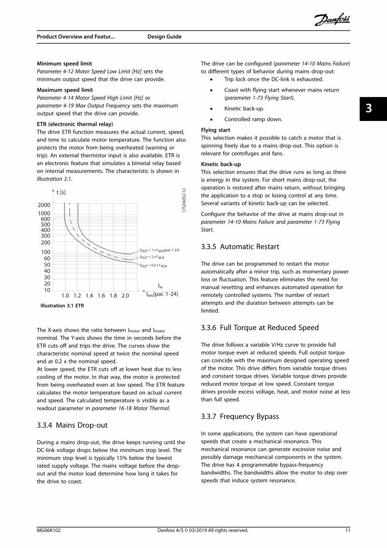
Electronic thermal relay (ETR)ETR is an electronic feature that simulates a bimetal relaybased on internal measurements. The characteristic isshown in Illustration 3.1.
Voltage limitThe inverter turns off to protect the transistors and the DClink capacitors when a certain hard-coded voltage level isreached.
OvertemperatureThe drive has built-in temperature sensors and reactsimmediately to critical values via hard-coded limits.
3.2.7 Locked Rotor Protection
There can be situations when the rotor is locked due toexcessive load or other factors. The locked rotor cannotproduce enough cooling, which in turn can overheat themotor winding. The drive is able to detect the locked rotorsituation with PM VVC+ control (parameter 30-22 LockedRotor Protection).
3.2.8 Automatic Derating
The drive constantly checks for the following critical levels:• High temperature on the control card or heat
sink.
• High motor load.
• High DC-link voltage.
• Low motor speed.
As a response to a critical level, the drive adjusts theswitching frequency. For high internal temperatures andlow motor speed, the drive can also force the PWM patternto SFAVM.
NOTICEThe automatic derating is different whenparameter 14-55 Output Filter is set to [2] Sine-Wave FilterFixed.
3.2.9 Automatic Energy Optimization
Automatic energy optimization (AEO) directs the drive tomonitor the load on the motor continuously and adjustthe output voltage to maximize efficiency. Under lightload, the voltage is reduced and the motor current isminimized. The motor benefits from:
• Increased efficiency.
• Reduced heating.
• Quieter operation.
There is no need to select a V/Hz curve because the driveautomatically adjusts motor voltage.
3.2.10 Automatic Switching FrequencyModulation
The drive generates short electrical pulses to form an ACwave pattern. The switching frequency is the rate of thesepulses. A low switching frequency (slow pulsing rate)causes audible noise in the motor, making a higherswitching frequency preferable. A high switchingfrequency, however, generates heat in the drive that canlimit the amount of current available to the motor.
Automatic switching frequency modulation regulates theseconditions automatically to provide the highest switchingfrequency without overheating the drive. By providing aregulated high switching frequency, it quiets motoroperating noise at slow speeds, when audible noise controlis critical, and produces full output power to the motorwhen required.
3.2.11 Automatic Derating for HighSwitching Frequency
The drive is designed for continuous, full-load operation atswitching frequencies between 1.5–2 kHz for 380–480 V.The frequency range depends on power size and voltagerating. A switching frequency exceeding the maximumallowed range generates increased heat in the drive andrequires the output current to be derated.
An automatic feature of the drive is load-dependentswitching frequency control. This feature allows the motorto benefit from as high a switching frequency as the loadallows.
Product Overview and Featur... Design Guide
MG06K102 Danfoss A/S © 03/2019 All rights reserved. 9
3 3
3.2.12 Power Fluctuation Performance
The drive withstands mains fluctuations such as:• Transients.
• Momentary drop-outs.
• Short voltage drops.
• Surges.
The drive automatically compensates for input voltages±10% from the nominal to provide full rated motor voltageand torque. With auto restart selected, the drive automat-ically powers up after a voltage trip. With flying start, thedrive synchronizes to motor rotation before start.
3.2.13 Resonance Damping
Resonance damping eliminates the high-frequency motorresonance noise. Automatic or manually selected frequencydamping is available.
3.2.14 Temperature-controlled Fans
Sensors in the drive regulate the operation of the internalcooling fans. Often, the cooling fans do not run during lowload operation, or when in sleep mode or standby. Thesesensors reduce noise, increase efficiency, and extend theoperating life of the fan.
3.2.15 EMC Compliance
Electromagnetic interference (EMI) and radio frequencyinterference (RFI) are disturbances that can affect anelectrical circuit due to electromagnetic induction orradiation from an external source. The drive is designed tocomply with the EMC product standard for drives IEC61800-3 and the European standard EN 55011. Motorcables must be shielded and properly terminated tocomply with the emission levels in EN 55011. For moreinformation regarding EMC performance, see chapter 7.13.1 EMC Test Results.
3.2.16 Galvanic Isolation of ControlTerminals
All control terminals and output relay terminals are galvan-ically isolated from mains power, which completelyprotects the controller circuitry from the input current. Theoutput relay terminals require their own grounding. Thisisolation meets the stringent protective extra-low voltage(PELV) requirements for isolation.
The components that make up the galvanic isolationare:
• Supply, including signal isolation.
• Gatedrive for the IGBTs, trigger transformers, andoptocouplers.
• The output current Hall effect transducers.
3.3 Custom Application Features
Custom application functions are the most commonfeatures programmed in the drive for enhanced systemperformance. They require minimum programming or set-up. See the programming guide for instructions onactivating these functions.
3.3.1 Automatic Motor Adaptation
Automatic motor adaptation (AMA) is an automated testprocedure used to measure the electrical characteristics ofthe motor. AMA provides an accurate electronic model ofthe motor, allowing the drive to calculate optimalperformance and efficiency. Running the AMA procedurealso maximizes the automatic energy optimization featureof the drive. AMA is performed without the motor rotatingand without uncoupling the load from the motor.
3.3.2 Built-in PID Controller
The built-in proportional, integral, derivative (PID)controller eliminates the need for auxiliary control devices.The PID controller maintains constant control of closed-loop systems where regulated pressure, flow, temperature,or other system requirements must be maintained.
The drive can use 2 feedback signals from 2 differentdevices, allowing the system to be regulated with differentfeedback requirements. The drive makes control decisionsby comparing the 2 signals to optimize systemperformance.
3.3.3 Motor Thermal Protection
To protect the application from serious damage, the driveoffers several dedicated features.
Torque limitThe torque limit protects the motor from being overloadedindependent of the speed. Torque limit is controlled inparameter 4-16 Torque Limit Motor Mode andparameter 4-17 Torque Limit Generator Mode.Parameter 14-25 Trip Delay at Torque Limit controls the timebefore the torque limit warning trips.
Current limitParameter 4-18 Current Limit controls the current limit, andparameter 14-24 Trip Delay at Current Limit controls thetime before the current limit warning trips.
Product Overview and Featur... VLT® AutomationDrive FC 361
10 Danfoss A/S © 03/2019 All rights reserved. MG06K102
33
Minimum speed limitParameter 4-12 Motor Speed Low Limit [Hz] sets theminimum output speed that the drive can provide.
Maximum speed limitParameter 4-14 Motor Speed High Limit [Hz] orparameter 4-19 Max Output Frequency sets the maximumoutput speed that the drive can provide.
ETR (electronic thermal relay)The drive ETR function measures the actual current, speed,and time to calculate motor temperature. The function alsoprotects the motor from being overheated (warning ortrip). An external thermistor input is also available. ETR isan electronic feature that simulates a bimetal relay basedon internal measurements. The characteristic is shown inIllustration 3.1.
1.21.0 1.4
30
1020
10060
4050
1.81.6 2.0
2000
500
200
400300
1000600
t [s]
175Z
A05
2.12
fOUT = 2 x f M,N
fOUT = 0.2 x f M,N
fOUT = 1 x f M,N(par. 1-23)
IMN(par. 1-24)IM
Illustration 3.1 ETR
The X-axis shows the ratio between Imotor and Imotor
nominal. The Y-axis shows the time in seconds before theETR cuts off and trips the drive. The curves show thecharacteristic nominal speed at twice the nominal speedand at 0.2 x the nominal speed.At lower speed, the ETR cuts off at lower heat due to lesscooling of the motor. In that way, the motor is protectedfrom being overheated even at low speed. The ETR featurecalculates the motor temperature based on actual currentand speed. The calculated temperature is visible as areadout parameter in parameter 16-18 Motor Thermal.
3.3.4 Mains Drop-out
During a mains drop-out, the drive keeps running until theDC-link voltage drops below the minimum stop level. Theminimum stop level is typically 15% below the lowestrated supply voltage. The mains voltage before the drop-out and the motor load determine how long it takes forthe drive to coast.
The drive can be configured (parameter 14-10 Mains Failure)to different types of behavior during mains drop-out:
• Trip lock once the DC-link is exhausted.
• Coast with flying start whenever mains return(parameter 1-73 Flying Start).
• Kinetic back-up.
• Controlled ramp down.
Flying startThis selection makes it possible to catch a motor that isspinning freely due to a mains drop-out. This option isrelevant for centrifuges and fans.
Kinetic back-upThis selection ensures that the drive runs as long as thereis energy in the system. For short mains drop-out, theoperation is restored after mains return, without bringingthe application to a stop or losing control at any time.Several variants of kinetic back-up can be selected.
Configure the behavior of the drive at mains drop-out inparameter 14-10 Mains Failure and parameter 1-73 FlyingStart.
3.3.5 Automatic Restart
The drive can be programmed to restart the motorautomatically after a minor trip, such as momentary powerloss or fluctuation. This feature eliminates the need formanual resetting and enhances automated operation forremotely controlled systems. The number of restartattempts and the duration between attempts can belimited.
3.3.6 Full Torque at Reduced Speed
The drive follows a variable V/Hz curve to provide fullmotor torque even at reduced speeds. Full output torquecan coincide with the maximum designed operating speedof the motor. This drive differs from variable torque drivesand constant torque drives. Variable torque drives providereduced motor torque at low speed. Constant torquedrives provide excess voltage, heat, and motor noise at lessthan full speed.
3.3.7 Frequency Bypass
In some applications, the system can have operationalspeeds that create a mechanical resonance. Thismechanical resonance can generate excessive noise andpossibly damage mechanical components in the system.The drive has 4 programmable bypass-frequencybandwidths. The bandwidths allow the motor to step overspeeds that induce system resonance.
Product Overview and Featur... Design Guide
MG06K102 Danfoss A/S © 03/2019 All rights reserved. 11
3 3

3.3.8 Motor Preheat
To preheat a motor in a cold or damp environment, a smallamount of DC current can be trickled continuously into themotor to protect it from condensation and cold starts. Thisfunction can eliminate the need for a space heater.
3.3.9 Programmable Set-ups
The drive has 4 set-ups that can be independentlyprogrammed. Using multi-setup, it is possible to switchbetween independently programmed functions activatedby digital inputs or a serial command. Independent set-upsare used, for example, to change references, or for day/night or summer/winter operation, or to control multiplemotors. The LCP shows the active set-up.
Set-up data can be copied from drive to drive bydownloading the information from the removable LCP.
3.3.10 Smart Logic Control (SLC)
Smart logic control (SLC) is a sequence of user-definedactions (see parameter 13-52 SL Controller Action [x])executed by the SLC when the associated user-definedevent (see parameter 13-51 SL Controller Event [x]) isevaluated as TRUE by the SLC.The condition for an event can be a particular status, orthat the output from a logic rule or a comparator operandbecomes TRUE. The condition leads to an associated actionas shown in Illustration 3.2.
. . .
. . .
Par. 13-11Comparator Operator
Par. 13-43Logic Rule Operator 2
Par. 13-51SL Controller Event
Par. 13-52SL Controller Action
130B
B671
.13
CoastStart timerSet Do X lowSelect set-up 2. . .
RunningWarningTorque limitDigital input X 30/2. . .
=TRUE longer than..
. . .
. . .
Illustration 3.2 SLC Event and Action
Events and actions are each numbered and linked in pairs(states), which means that when event [0] is fulfilled(attains the value TRUE), action [0] is executed. After the 1st
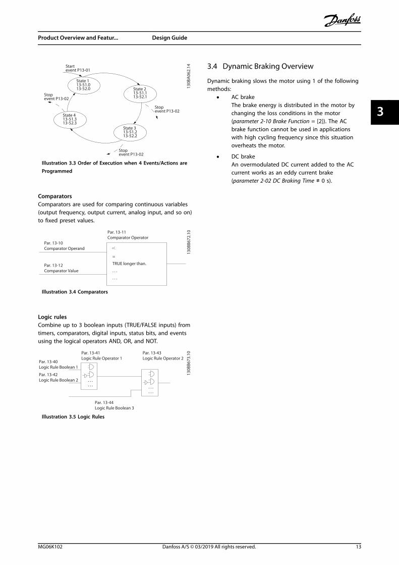
action is executed, the conditions of the next event areevaluated. If this event is evaluated as true, then thecorresponding action is executed. Only 1 event isevaluated at any time. If an event is evaluated as false,nothing happens in the SLC during the current scaninterval and no other events are evaluated. When the SLCstarts, it only evaluates event [0] during each scan interval.Only when event [0] is evaluated as true, the SLC executesaction [0] and starts evaluating the next event. It ispossible to program 1–20 events and actions.When the last event/action has been executed, thesequence starts over again from event [0]/action [0].Illustration 3.3 shows an example with 4 event/actions:
Product Overview and Featur... VLT® AutomationDrive FC 361
12 Danfoss A/S © 03/2019 All rights reserved. MG06K102
33
130B
A06
2.14
State 113-51.013-52.0 State 2
13-51.113-52.1
Startevent P13-01
State 313-51.213-52.2
State 413-51.313-52.3
Stopevent P13-02
Stopevent P13-02
Stopevent P13-02
Illustration 3.3 Order of Execution when 4 Events/Actions areProgrammed
ComparatorsComparators are used for comparing continuous variables(output frequency, output current, analog input, and so on)to fixed preset values.
Par. 13-11Comparator Operator
=
TRUE longer than.
. . .
. . .
Par. 13-10Comparator Operand
Par. 13-12Comparator Value
130B
B672
.10
Illustration 3.4 Comparators
Logic rulesCombine up to 3 boolean inputs (TRUE/FALSE inputs) fromtimers, comparators, digital inputs, status bits, and eventsusing the logical operators AND, OR, and NOT.
. . .
. . . . . .. . .
Par. 13-43Logic Rule Operator 2
Par. 13-41Logic Rule Operator 1
Par. 13-40Logic Rule Boolean 1
Par. 13-42Logic Rule Boolean 2
Par. 13-44Logic Rule Boolean 3
130B
B673
.10
Illustration 3.5 Logic Rules
3.4 Dynamic Braking Overview
Dynamic braking slows the motor using 1 of the followingmethods:
• AC brakeThe brake energy is distributed in the motor bychanging the loss conditions in the motor(parameter 2-10 Brake Function = [2]). The ACbrake function cannot be used in applicationswith high cycling frequency since this situationoverheats the motor.
• DC brakeAn overmodulated DC current added to the ACcurrent works as an eddy current brake(parameter 2-02 DC Braking Time ≠ 0 s).
Product Overview and Featur... Design Guide
MG06K102 Danfoss A/S © 03/2019 All rights reserved. 13
3 3
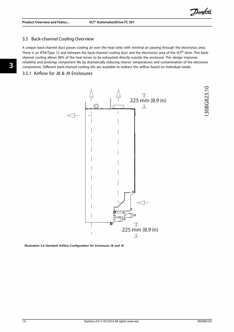
3.5 Back-channel Cooling Overview
A unique back-channel duct passes cooling air over the heat sinks with minimal air passing through the electronics area.There is an IP54/Type 12 seal between the back-channel cooling duct and the electronics area of the VLT® drive. This back-channel cooling allows 90% of the heat losses to be exhausted directly outside the enclosure. This design improvesreliability and prolongs component life by dramatically reducing interior temperatures and contamination of the electroniccomponents. Different back-channel cooling kits are available to redirect the airflow based on individual needs.
3.5.1 Airflow for J8 & J9 Enclosures
130B
G82
3.10
225 mm (8.9 in)
225 mm (8.9 in)
Illustration 3.6 Standard Airflow Configuration for Enclosures J8 and J9
Product Overview and Featur... VLT® AutomationDrive FC 361
14 Danfoss A/S © 03/2019 All rights reserved. MG06K102
33

4 Options and Accessories Overview
4.1 Fieldbus Devices
This section describes the fieldbus devices that areavailable with the VLT® AutomationDrive FC 361 series.Using a fieldbus device reduces system cost, delivers fasterand more efficient communication, and provides an easieruser interface. For ordering numbers, refer tochapter 10.2 Ordering Numbers for Options and Accessories.
4.1.1 VLT® PROFIBUS DP-V1 MCA 101
The VLT® PROFIBUS DP-V1 MCA 101 provides:• Wide compatibility, a high level of availability,
support for all major PLC vendors, and compati-bility with future versions.
• Fast, efficient communication, transparent instal-lation, advanced diagnosis, and parameterizationand auto-configuration of process data via a GSDfile.
• Acyclic parameterization using PROFIBUS DP-V1,PROFIdrive, or Danfoss FC profile state machines.
4.1.2 VLT® PROFINET MCA 120
The VLT® PROFINET MCA 120 combines the highestperformance with the highest degree of openness. Theoption is designed so that many of the features from theVLT® PROFIBUS MCA 101 can be reused, minimizing usereffort to migrate PROFINET and securing the investment ina PLC program.
• Same PPO types as the VLT® PROFIBUS DP V1MCA 101 for easy migration to PROFINET.
• Built-in web server for remote diagnosis andreading out of basic drive parameters.
• Supports MRP.
• Supports DP-V1. Diagnostic allows easy, fast, andstandardized handling of warning and faultinformation into the PLC, improving bandwidth inthe system.
• Implementation in accordance with ConformanceClass B.
4.2 Functional Extensions
This section describes the functional extension options thatare available with the VLT® AutomationDrive FC 361 series.For ordering numbers, refer to chapter 10.2 OrderingNumbers for Options and Accessories.
4.2.1 VLT® General Purpose I/O ModuleMCB 101
The VLT® General Purpose I/O Module MCB 101 offers anextended number of control inputs and outputs:
• 3 digital inputs 0–24 V: Logic 0 < 5 V; Logic 1 >10 V.
• 2 analog inputs 0–10 V: Resolution 10 bits plussign.
• 2 digital outputs NPN/PNP push-pull.
• 1 analog output 0/4–20 mA.
• Spring-loaded connection.
4.2.2 VLT® Encoder Input MCB 102
The MCB 102 option offers the possibility to connectvarious types of incremental and absolute encoders. Theconnected encoder can be used for closed-loop speedcontrol and closed-loop flux motor control.
The following encoder types are supported:• 5 V TTL (RS 422).
• 1VPP SinCos.
4.2.3 VLT® Resolver Option MCB 103
The MCB 103 option enables connection of a resolver toprovide speed feedback from the motor.
• Primary voltage: 2–8 Vrms.
• Primary frequency: 2.0–15 kHz.
• Primary maximum current: 50 mA rms.
• Secondary input voltage: 4 Vrms.
• Spring-loaded connection.
Options and Accessories Ove... Design Guide
MG06K102 Danfoss A/S © 03/2019 All rights reserved. 15
4 4

5 Specifications
5.1 Electrical Data, 380-480 V
VLT® AutomationDrive FC 361 N90K N110 N132 N160
High/normal overload NO HO NO HO NO HO NO(High overload=150% current during 60 s, normaloverload=110% current during 60 s)
Typical shaft output at 400 V [kW] 90 90 110 110 132 132 160
Typical shaft output at 460 V [hp] 125 125 150 150 200 200 250
Enclosure size J8
Output current (3-phase)
Continuous (at 400 V) [A] 177 177 212 212 260 260 315
Intermittent (60 s overload) (at 400 V) [A] 195 266 233 318 286 390 347
Continuous (at 460 V) [A] 160 160 190 190 240 240 302
Intermittent (60 s overload) (at 460 V) [kVA] 176 240 209 285 264 360 332
Continuous kVA (at 400 V) [kVA] 123 123 147 147 180 180 218
Continuous kVA (at 460 V) [kVA] 127 127 151 151 191 191 241
Maximum input current
Continuous (at 400 V) [A] 171 171 204 204 251 251 304
Continuous (at 460 V) [A] 154 154 183 183 231 231 291
Maximum number and size of cables per phase
Mains and motor [mm2 (AWG)] 2x95 (2x3/0)
Maximum external mains fuses [A]1) 315 315 350 400
Estimated power loss at 400 V [W]2), 3) 2031 2031 2559 2289 2954 2923 3770
Estimated power loss at 460 V [W]2), 3) 1828 1828 2261 2051 2724 2089 3628
Efficiency3) 0.98
Output frequency [Hz] 0–590
Heat sink overtemperature trip [°C (°F)] 110 (230)
Weight, enclosure protection rating IP20 kg (lbs) 98 (216)
Efficiency3) 0.98
Output frequency [Hz] 0–590
Heat sink overtemperature trip [°C (°F)] 110 (230)
Control card overtemperature trip [°C (°F)] 75 (167)
Table 5.1 Electrical Data for Enclosures J8, Mains Supply 3x380–480 V AC
1) For fuse ratings, see chapter 7.5 Fuses and Circuit Breakers.
2) Typical power loss is at normal conditions and expected to be within ±15% (tolerance relates to variety in voltage and cable conditions). Thesevalues are based on a typical motor efficiency (IE/IE3 border line). Lower efficiency motors add to the power loss in the drive. Applies todimensioning of drive cooling. If the switching frequency is higher than the default setting, the power losses can increase. LCP and typical controlcard power consumptions are included. For power loss data according to EN 50598-2, refer to drives.danfoss.com/knowledge-center/energy-efficiency-directive/#/. Options and customer load can add up to 30 W to the losses, though usually a fully loaded control card and options forslots A and B each add only 4 W.3) Measured using 5 m (16.4 ft) shielded motor cables at rated load and rated frequency. Efficiency measured at nominal current. For energyefficiency class, see chapter 5.4 Ambient Conditions. For part load losses, see drives.danfoss.com/knowledge-center/energy-efficiency-directive/#/.
Specifications VLT® AutomationDrive FC 361
16 Danfoss A/S © 03/2019 All rights reserved. MG06K102
55
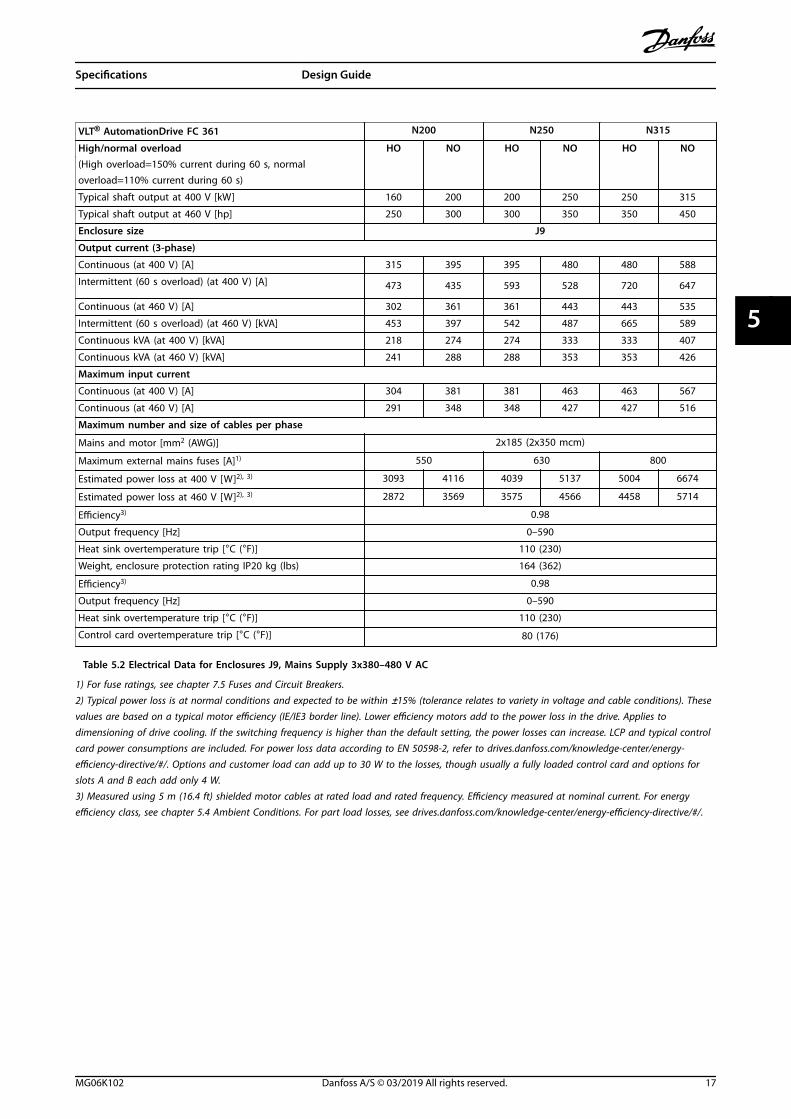
VLT® AutomationDrive FC 361 N200 N250 N315
High/normal overload HO NO HO NO HO NO(High overload=150% current during 60 s, normaloverload=110% current during 60 s)
Typical shaft output at 400 V [kW] 160 200 200 250 250 315
Typical shaft output at 460 V [hp] 250 300 300 350 350 450
Enclosure size J9
Output current (3-phase)
Continuous (at 400 V) [A] 315 395 395 480 480 588
Intermittent (60 s overload) (at 400 V) [A] 473 435 593 528 720 647
Continuous (at 460 V) [A] 302 361 361 443 443 535
Intermittent (60 s overload) (at 460 V) [kVA] 453 397 542 487 665 589
Continuous kVA (at 400 V) [kVA] 218 274 274 333 333 407
Continuous kVA (at 460 V) [kVA] 241 288 288 353 353 426
Maximum input current
Continuous (at 400 V) [A] 304 381 381 463 463 567
Continuous (at 460 V) [A] 291 348 348 427 427 516
Maximum number and size of cables per phase
Mains and motor [mm2 (AWG)] 2x185 (2x350 mcm)
Maximum external mains fuses [A]1) 550 630 800
Estimated power loss at 400 V [W]2), 3) 3093 4116 4039 5137 5004 6674
Estimated power loss at 460 V [W]2), 3) 2872 3569 3575 4566 4458 5714
Efficiency3) 0.98
Output frequency [Hz] 0–590
Heat sink overtemperature trip [°C (°F)] 110 (230)
Weight, enclosure protection rating IP20 kg (lbs) 164 (362)
Efficiency3) 0.98
Output frequency [Hz] 0–590
Heat sink overtemperature trip [°C (°F)] 110 (230)
Control card overtemperature trip [°C (°F)] 80 (176)
Table 5.2 Electrical Data for Enclosures J9, Mains Supply 3x380–480 V AC
1) For fuse ratings, see chapter 7.5 Fuses and Circuit Breakers.
2) Typical power loss is at normal conditions and expected to be within ±15% (tolerance relates to variety in voltage and cable conditions). Thesevalues are based on a typical motor efficiency (IE/IE3 border line). Lower efficiency motors add to the power loss in the drive. Applies todimensioning of drive cooling. If the switching frequency is higher than the default setting, the power losses can increase. LCP and typical controlcard power consumptions are included. For power loss data according to EN 50598-2, refer to drives.danfoss.com/knowledge-center/energy-efficiency-directive/#/. Options and customer load can add up to 30 W to the losses, though usually a fully loaded control card and options forslots A and B each add only 4 W.3) Measured using 5 m (16.4 ft) shielded motor cables at rated load and rated frequency. Efficiency measured at nominal current. For energyefficiency class, see chapter 5.4 Ambient Conditions. For part load losses, see drives.danfoss.com/knowledge-center/energy-efficiency-directive/#/.
Specifications Design Guide
MG06K102 Danfoss A/S © 03/2019 All rights reserved. 17
5 5
5.2 Mains Supply
Mains supply (L1, L2, L3)Supply voltage 380–480 V ±10%
Mains voltage low/mains voltage drop-out:During low mains voltage or a mains drop-out, the drive continues until the DC-link voltage drops below the minimum stoplevel, which corresponds typically to 15% below the lowest rated supply voltage of the drive. Power-up and full torque cannot beexpected at mains voltage lower than 10% below the lowest rated supply voltage of the drive.
Supply frequency 50/60 Hz ±5%Maximum imbalance temporary between mains phases 3.0% of rated supply voltage1)
True power factor (λ) ≥0.9 nominal at rated loadDisplacement power factor (cos Φ) near unity (>0.98)Switching on input supply L1, L2, L3 (power-ups) Maximum 1 time/2 minuteEnvironment according to EN60664-1 Overvoltage category III/pollution degree 2
The drive is suitable for use on a circuit capable of delivering up to 100 kA short circuit current rating (SCCR) at 480/600 V.1) Calculations based on IEC61800-3.
5.3 Motor Output and Motor Data
Motor output (U, V, W)Output voltage 0–100% of supply voltageOutput frequency 0–590 Hz1)
Output frequency in flux mode 0–300 HzSwitching on output UnlimitedRamp times 0.01–3600 s
1) Dependent on voltage and power.
Torque characteristicsStarting torque (constant torque) Maximum 150% for 60 s1), 2)
Overload torque (constant torque) Maximum 150% for 60 s1), 2)
1) Percentage relates to the nominal current of the drive.2) Once every 10 minutes.
5.4 Ambient Conditions
EnvironmentJ8/J9 enclosure IP20/ChassisVibration test (standard/ruggedized) 0.7 g/1.0 gRelative humidity 5%–95% (IEC 721-3-3; Class 3K3 (non-condensing) during operation)Aggressive environment (IEC 60068-2-43) H2S test Class KdAggressive gases (IEC 60721-3-3) Class 3C3Test method according to IEC 60068-2-43 H2S (10 days)Ambient temperature (at SFAVM switching mode)- with derating Maximum 55 °C (131 °F)1)
- with full output power of typical EFF2 motors (up to 90% output current) Maximum 50 °C (122 °F)1)
- at full continuous FC output current Maximum 45 °C (113 °F)1)
Minimum ambient temperature during full-scale operation 0 °C (32 °F)Minimum ambient temperature at reduced performance -10 °C (14 °F)Temperature during storage/transport -25 to +65/70 °C (13 to 149/158 °F)Maximum altitude above sea level without derating 1000 m (3281 ft)Maximum altitude above sea level with derating 3000 m (9842 ft)
1) For more information on derating, see chapter 6.6 Derating.
EMC standards, Emission EN 61800-3
Specifications VLT® AutomationDrive FC 361
18 Danfoss A/S © 03/2019 All rights reserved. MG06K102
55

EMC standards, Immunity EN 61800-3Energy efficiency class1) IE2
1) Determined according to EN 50598-2 at:
• Rated load.
• 90% rated frequency.
• Switching frequency factory setting.
• Switching pattern factory setting.
5.5 Cable Specifications
Cable lengths and cross-sections for control cablesMaximum motor cable length, shielded 150 m (492 ft)Maximum motor cable length, unshielded 300 m (984 ft)Maximum cross-section to motor and mains See chapter 5.1 Electrical Data, 380-480 V1)
Maximum cross-section to control terminals, rigid wire 1.5 mm2/16 AWG (2x0.75 mm2)Maximum cross-section to control terminals, flexible cable 1 mm2/18 AWGMaximum cross-section to control terminals, cable with enclosed core 0.5 mm2/20 AWGMinimum cross-section to control terminals 0.25 mm2/23 AWG
1) For power cables, see electrical data in chapter 5.1 Electrical Data, 380-480 V.
5.6 Control Input/Output and Control Data
Digital inputsProgrammable digital inputs 4 (6)Terminal number 18, 19, 271), 291), 32, 33Logic PNP or NPNVoltage level 0–24 V DCVoltage level, logic 0 PNP <5 V DCVoltage level, logic 1 PNP >10 V DCVoltage level, logic 0 NPN >19 V DCVoltage level, logic 1 NPN <14 V DCMaximum voltage on input 28 V DCInput resistance, Ri Approximately 4 kΩ
All digital inputs are galvanically isolated from the supply voltage (PELV) and other high-voltage terminals.1) Terminals 27 and 29 can also be programmed as outputs.
Analog inputsNumber of analog inputs 2Terminal number 53, 54Modes Voltage or currentMode select Switches A53 and A54Voltage mode Switch A53/A54=(U)Voltage level 0 V to +10 V (scaleable)Input resistance, Ri Approximately 10 kΩMaximum voltage ±20 VCurrent mode Switch A53/A54=(I)Current level 0/4 to 20 mA (scaleable)Input resistance, Ri Approximately 200 ΩMaximum current 30 mAResolution for analog inputs 10 bit (+ sign)Accuracy of analog inputs Maximum error 0.5% of full scaleBandwidth 100 Hz
The analog inputs are galvanically isolated from the supply voltage (PELV) and other high-voltage terminals.
Specifications Design Guide
MG06K102 Danfoss A/S © 03/2019 All rights reserved. 19
5 5

Mains
Functionalisolation
PELV isolation
Motor
DC-bus
Highvoltage
Control+24 V
RS485
18
37
130B
A11
7.10
Illustration 5.1 PELV Isolation
Pulse inputsProgrammable pulse inputs 2Terminal number pulse 29, 33Maximum frequency at terminal 29, 33 (push-pull driven) 110 kHzMaximum frequency at terminal 29, 33 (open collector) 5 kHzMinimum frequency at terminal 29, 33 4 HzVoltage level See Digital Inputs in chapter 5.6 Control Input/Output and Control DataMaximum voltage on input 28 V DCInput resistance, Ri Approximately 4 kΩPulse input accuracy (0.1–1 kHz) Maximum error: 0.1% of full scale
Analog outputNumber of programmable analog outputs 1Terminal number 42Current range at analog output 0/4–20 mAMaximum resistor load to common at analog output 500 ΩAccuracy on analog output Maximum error: 0.8% of full scaleResolution on analog output 8 bit
The analog output is galvanically isolated from the supply voltage (PELV) and other high-voltage terminals.
Control card, RS485 serial communicationTerminal number 68 (P, TX+, RX+), 69 (N, TX-, RX-)Terminal number 61 Common for terminals 68 and 69
The RS485 serial communication circuit is functionally separated from other central circuits and galvanically isolated from thesupply voltage (PELV).
Digital outputProgrammable digital/pulse outputs 2Terminal number 27, 291)
Voltage level at digital/frequency output 0–24 VMaximum output current (sink or source) 40 mAMaximum load at frequency output 1 kΩMaximum capacitive load at frequency output 10 nFMinimum output frequency at frequency output 0 HzMaximum output frequency at frequency output 32 kHzAccuracy of frequency output Maximum error: 0.1% of full scaleResolution of frequency outputs 12 bit
1) Terminals 27 and 29 can also be programmed as inputs.
The digital output is galvanically isolated from the supply voltage (PELV) and other high-voltage terminals.
Specifications VLT® AutomationDrive FC 361
20 Danfoss A/S © 03/2019 All rights reserved. MG06K102
55

Control card, 24 V DC outputTerminal number 12, 13Maximum load 200 mA
The 24 V DC supply is galvanically isolated from the supply voltage (PELV), but has the same potential as the analog and digitalinputs and outputs.
Relay outputsProgrammable relay outputs 2Maximum cross-section to relay terminals 2.5 mm2 (12 AWG)Minimum cross-section to relay terminals 0.2 mm2 (30 AWG)Length of stripped wire 8 mm (0.3 in)Relay 01 terminal number 1–3 (break), 1–2 (make)Maximum terminal load (AC-1)1) on 1–2 (NO) (Resistive load)2), 3) 400 V AC, 2 AMaximum terminal load (AC-15)1) on 1–2 (NO) (Inductive load @ cosφ 0.4) 240 V AC, 0.2 AMaximum terminal load (DC-1)1) on 1–2 (NO) (Resistive load) 80 V DC, 2 AMaximum terminal load (DC-13)1) on 1–2 (NO) (Inductive load) 24 V DC, 0.1 AMaximum terminal load (AC-1)1) on 1–3 (NC) (Resistive load) 240 V AC, 2 AMaximum terminal load (AC-15)1) on 1–3 (NC) (Inductive load @ cosφ 0.4) 240 V AC, 0.2 AMaximum terminal load (DC-1)1) on 1–3 (NC) (Resistive load) 50 V DC, 2 AMaximum terminal load (DC-13)1) on 1–3 (NC) (Inductive load) 24 V DC, 0.1 AMinimum terminal load on 1–3 (NC), 1–2 (NO) 24 V DC 10 mA, 24 V AC 2 mAEnvironment according to EN 60664-1 Overvoltage category III/pollution degree 2Relay 02 terminal number 4–6 (break), 4–5 (make)Maximum terminal load (AC-1)1) on 4–5 (NO) (Resistive load)2), 3) 400 V AC, 2 AMaximum terminal load (AC-15)1) on 4–5 (NO) (Inductive load @ cosφ 0.4) 240 V AC, 0.2 AMaximum terminal load (DC-1)1) on 4–5 (NO) (Resistive load) 80 V DC, 2 AMaximum terminal load (DC-13)1) on 4–5 (NO) (Inductive load) 24 V DC, 0.1 AMaximum terminal load (AC-1)1) on 4–6 (NC) (Resistive load) 240 V AC, 2 AMaximum terminal load (AC-15)1) on 4–6 (NC) (Inductive load @ cosφ 0.4) 240 V AC, 0.2 AMaximum terminal load (DC-1)1) on 4–6 (NC) (Resistive load) 50 V DC, 2 AMaximum terminal load (DC-13)1) on 4–6 (NC) (Inductive load) 24 V DC, 0.1 AMinimum terminal load on 4–6 (NC), 4–5 (NO) 24 V DC 10 mA, 24 V AC 2 mAEnvironment according to EN 60664-1 Overvoltage category III/pollution degree 2
The relay contacts are galvanically isolated from the rest of the circuit by reinforced isolation (PELV).1) IEC 60947 part 4 and 5.2) Overvoltage Category II.
Control card, +10 V DC outputTerminal number 50Output voltage 10.5 V ±0.5 VMaximum load 25 mA
The 10 V DC supply is galvanically isolated from the supply voltage (PELV) and other high-voltage terminals.
Control characteristicsResolution of output frequency at 0–1000 Hz ±0.003 HzSystem response time (terminals 18, 19, 27, 29, 32, 33) ≤2 m/sSpeed control range (open loop) 1:100 of synchronous speedSpeed accuracy (open loop) 30–4000 RPM: Maximum error of ±8 RPM
All control characteristics are based on a 4-pole asynchronous motor.
Control card performanceScan interval 5 M/S
Specifications Design Guide
MG06K102 Danfoss A/S © 03/2019 All rights reserved. 21
5 5
Control card, USB serial communicationUSB standard 1.1 (full speed)USB plug USB type B device plug
NOTICEConnection to PC is carried out via a standard host/device USB cable.The USB connection is galvanically isolated from the supply voltage (PELV) and other high-voltage terminals.The USB connection is not galvanically isolated from ground. Use only isolated laptop/PC as connection to the USBconnector on the drive or an isolated USB cable/converter.
5.7 Enclosure Weights
Enclosure 380–480 V
J8 98 (216)
J9 164 (362)
Table 5.3 Enclosure J8–J9 Weights, kg (lb)
Specifications VLT® AutomationDrive FC 361
22 Danfoss A/S © 03/2019 All rights reserved. MG06K102
55
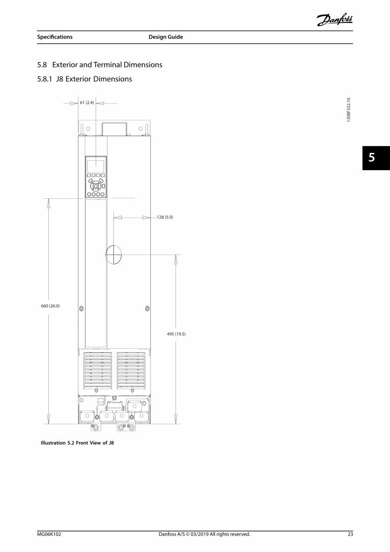
5.8 Exterior and Terminal Dimensions
5.8.1 J8 Exterior Dimensions
130B
F322
.10
61 (2.4)
128 (5.0)
495 (19.5)
660 (26.0)
Illustration 5.2 Front View of J8
Specifications Design Guide
MG06K102 Danfoss A/S © 03/2019 All rights reserved. 23
5 5

148 (5.8)
20 (0.8)
130B
F801
.10
844 (33.2)
39 (1.5)
375 (14.8)
82 (3.2)
18 (0.7)
Illustration 5.3 Side View of J8
Specifications VLT® AutomationDrive FC 361
24 Danfoss A/S © 03/2019 All rights reserved. MG06K102
55
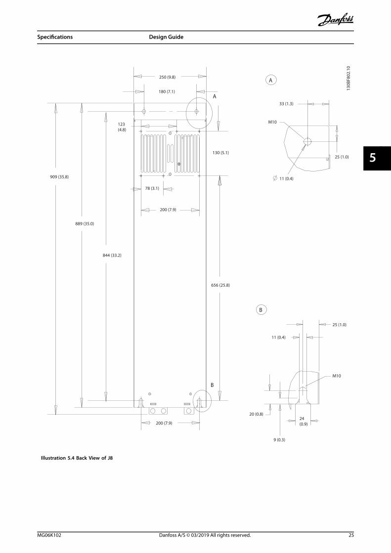
656 (25.8)
200 (7.9)
200 (7.9)
130 (5.1)
889 (35.0)
909 (35.8)
844 (33.2)
78 (3.1)
123 (4.8)
250 (9.8)
180 (7.1)
A
B
A
B
33 (1.3)
11 (0.4)
25 (1.0)
11 (0.4)
20 (0.8)
9 (0.3)
24 (0.9)
25 (1.0)
M10
M10
130B
F802
.10
Illustration 5.4 Back View of J8
Specifications Design Guide
MG06K102 Danfoss A/S © 03/2019 All rights reserved. 25
5 5
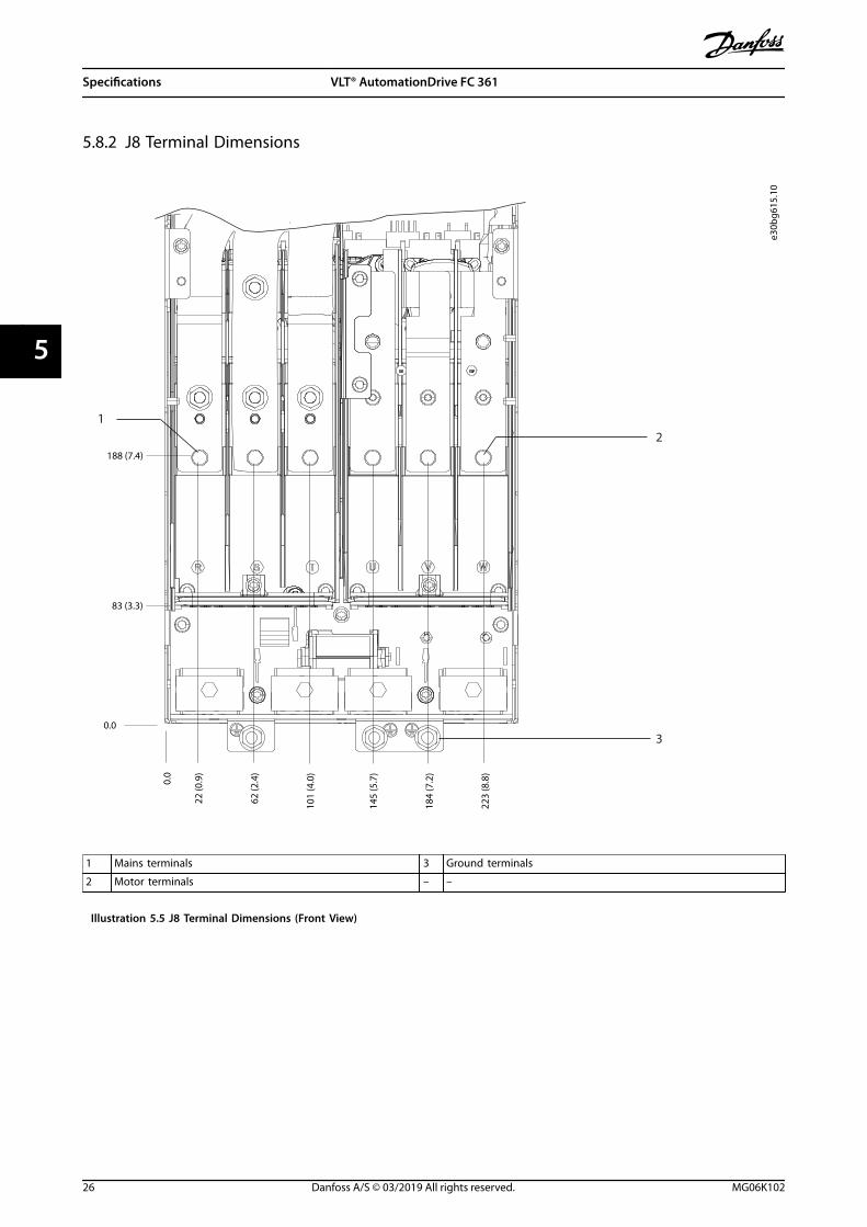
5.8.2 J8 Terminal Dimensions
e30b
g615
.10
83 (3.3)
0.0
188 (7.4)
22 (0
.9)
62 (2
.4)
101
(4.0
)
145
(5.7
)
184
(7.2
)
223
(8.8
)
0.0
12
3
1 Mains terminals 3 Ground terminals
2 Motor terminals – –
Illustration 5.5 J8 Terminal Dimensions (Front View)
Specifications VLT® AutomationDrive FC 361
26 Danfoss A/S © 03/2019 All rights reserved. MG06K102
55
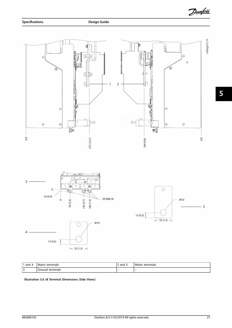
M10
13 (0.5)
32 (1.3)
59 (2
.3)
10 (0.4)
244
(9.6
)
272
(10.
7)0.0
0.0
1 2
4
3
5
M10
13 (0.5)
32 (1.3)
145
(5.7
)
182
(7.2
) 3X M8x18
0
0
e30b
g573
.10
1 and 4 Mains terminals 2 and 5 Motor terminals
3 Ground terminals – –
Illustration 5.6 J8 Terminal Dimensions (Side Views)
Specifications Design Guide
MG06K102 Danfoss A/S © 03/2019 All rights reserved. 27
5 5
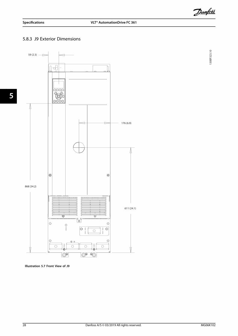
5.8.3 J9 Exterior Dimensions
130B
F323
.10
176 (6.9)
611 (24.1)
59 (2.3)
868 (34.2)
Illustration 5.7 Front View of J9
Specifications VLT® AutomationDrive FC 361
28 Danfoss A/S © 03/2019 All rights reserved. MG06K102
55
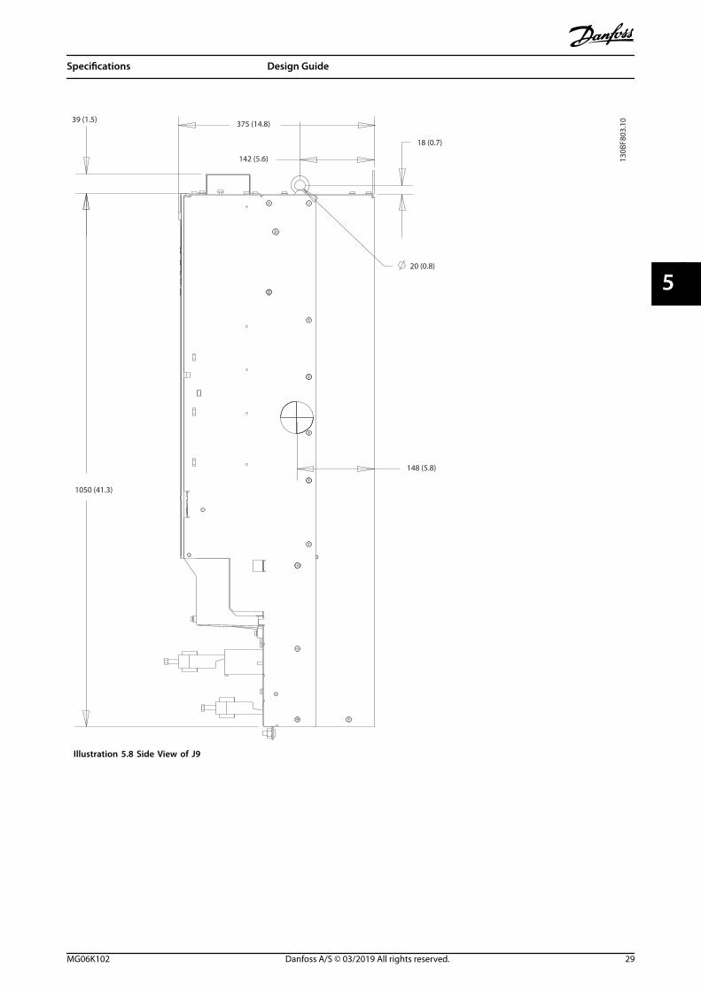
130B
F803
.10
20 (0.8)
148 (5.8)
18 (0.7)
1050 (41.3)
39 (1.5) 375 (14.8)
142 (5.6)
Illustration 5.8 Side View of J9
Specifications Design Guide
MG06K102 Danfoss A/S © 03/2019 All rights reserved. 29
5 5

B
130B
F804
.10
B
857 (33.7)
A
A
320 (12.6)
280 (11.0)
350 (13.8)
107 (4.2)
213 (8.4)1122 (44.2)
1096 (43.1)
1051 (41.4)
271 (10.7)
130 (5.1) 25 (1.0)
33 (1.3)
11 (0.4)
40 (1.6)
11 (0.4)
9 (0.3)
20 (0.8)24 (0.9)
Illustration 5.9 Back View of J9
Specifications VLT® AutomationDrive FC 361
30 Danfoss A/S © 03/2019 All rights reserved. MG06K102
55

5.8.4 J9 Terminal Dimensions
33 (1
.3)
91 (3
.6)
149
(5.8
)
211
(8.3
)
265
(10.
4)
319
(12.
6)
200 (7.9)
319 (12.6)
e30b
g616
.10
0.0
o.o
1
2
3
1 Mains terminals 3 Ground terminals
2 Motor terminals – –
Illustration 5.10 J9 Terminal Dimensions (Front View)
Specifications Design Guide
MG06K102 Danfoss A/S © 03/2019 All rights reserved. 31
5 5
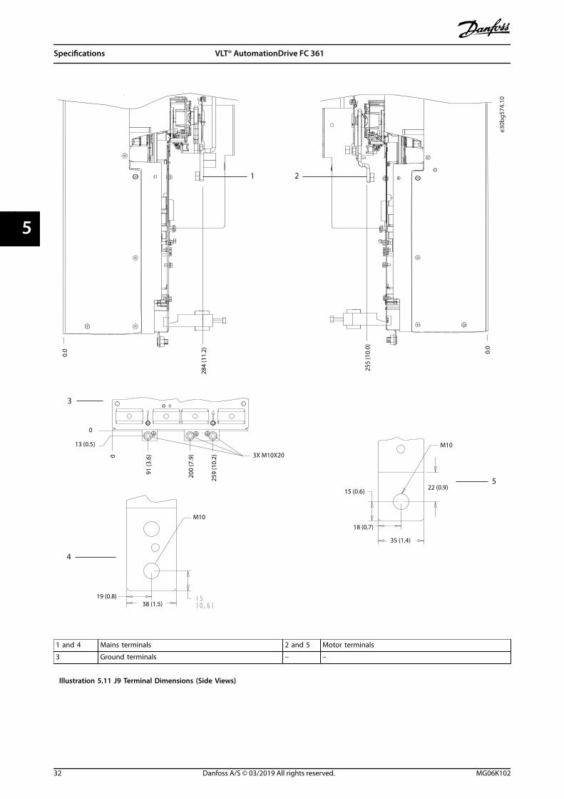
4
3
91 (3
.6)
13 (0.5)
200
(7.9
)
259
(10.
2) 3X M10X20
0
0
M10
19 (0.8)38 (1.5)
255
(10.
0)
284
(11.
2)
0.0 0.
0
1 2
5
M10
22 (0.9)
35 (1.4)
15 (0.6)
18 (0.7)
e30b
g574
.10
1 and 4 Mains terminals 2 and 5 Motor terminals
3 Ground terminals – –
Illustration 5.11 J9 Terminal Dimensions (Side Views)
Specifications VLT® AutomationDrive FC 361
32 Danfoss A/S © 03/2019 All rights reserved. MG06K102
55

6 Mechanical Installation Considerations
6.1 Storage
Store the drive in a dry location. Keep the equipmentsealed in its packaging until installation. Refer to chapter 5.4 Ambient Conditions for recommended ambienttemperature.
Periodic forming (capacitor charging) is not necessaryduring storage unless storage exceeds 12 months.
6.2 Lifting the Unit
Always lift the drive using the dedicated lifting eyes. Toavoid bending the lifting holes, use a bar.
WARNINGRISK OF INJURY OR DEATHFollow local safety regulations for lifting heavy weights.Failure to follow recommendations and local safetyregulations can result in death or serious injury.
• Ensure that the lifting equipment is in properworking condition.
• See chapter 3 Product Overview and Features forthe weight of the different enclosure sizes.
• Maximum diameter for bar: 20 mm (0.8 in).
• The angle from the top of the drive to thelifting cable: 60° or greater.
e30b
g512
.11
65° min
Illustration 6.1 Recommended Lifting Method
Mechanical Installation Con... Design Guide
MG06K102 Danfoss A/S © 03/2019 All rights reserved. 33
6 6
6.3 Operating Environment
In environments with airborne liquids, particles, orcorrosive gases, ensure that the IP/Type rating of theequipment matches the installation environment. Forspecifications regarding ambient conditions, seechapter 5.4 Ambient Conditions.
NOTICECONDENSATIONMoisture can condense on the electronic componentsand cause short circuits. Avoid installation in areassubject to frost. Install an optional space heater whenthe drive is colder than the ambient air. Operating instandby mode reduces the risk of condensation as longas the power dissipation keeps the circuitry free ofmoisture.
NOTICEEXTREME AMBIENT CONDITIONSHot or cold temperatures compromise unit performanceand longevity.
• Do not operate in environments where theambient temperature exceeds 55 °C (131 °F).
• The drive can operate at temperatures down to-10 °C (14 °F). However, proper operation atrated load is only guaranteed at 0 °C (32 °F) orhigher.
• If temperature exceeds ambient temperaturelimits, extra air conditioning of the cabinet orinstallation site is required.
6.3.1 Gases
Aggressive gases, such as hydrogen sulphide, chlorine, orammonia can damage the electrical and mechanicalcomponents. The unit uses conformal-coated circuit boardsto reduce the effects of aggressive gases. For conformal-coating class specifications and ratings, seechapter 5.4 Ambient Conditions.
6.3.2 Dust
When installing the drive in dusty environments, payattention to the following:
Periodic maintenanceWhen dust accumulates on electronic components, it actsas a layer of insulation. This layer reduces the coolingcapacity of the components, and the components becomewarmer. The hotter environment decreases the life of theelectronic components.
Keep the heat sink and fans free from dust build-up. Formore service and maintenance information, refer to theoperating guide.
Cooling fansFans provide airflow to cool the drive. When fans areexposed to dusty environments, the dust can damage thefan bearings and cause premature fan failure. Also, dustcan accumulate on fan blades causing an imbalance whichprevents the fans from properly cooling the unit.
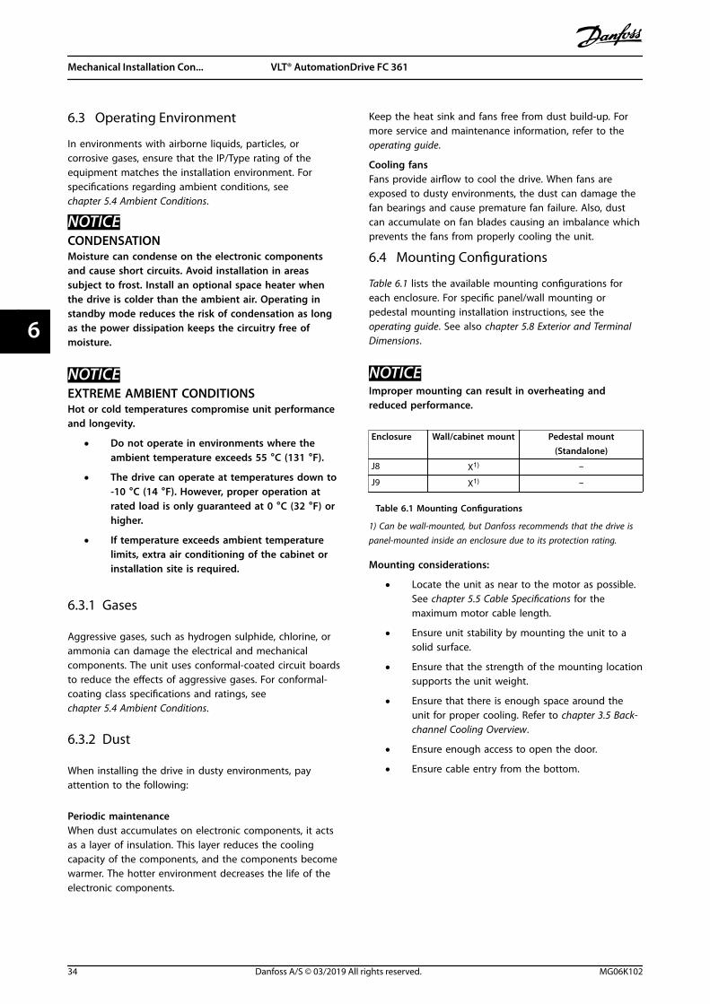
6.4 Mounting Configurations
Table 6.1 lists the available mounting configurations foreach enclosure. For specific panel/wall mounting orpedestal mounting installation instructions, see theoperating guide. See also chapter 5.8 Exterior and TerminalDimensions.
NOTICEImproper mounting can result in overheating andreduced performance.
Enclosure Wall/cabinet mount Pedestal mount(Standalone)
J8 X1) –
J9 X1) –
Table 6.1 Mounting Configurations
1) Can be wall-mounted, but Danfoss recommends that the drive ispanel-mounted inside an enclosure due to its protection rating.
Mounting considerations:
• Locate the unit as near to the motor as possible.See chapter 5.5 Cable Specifications for themaximum motor cable length.
• Ensure unit stability by mounting the unit to asolid surface.
• Ensure that the strength of the mounting locationsupports the unit weight.
• Ensure that there is enough space around theunit for proper cooling. Refer to chapter 3.5 Back-channel Cooling Overview.
• Ensure enough access to open the door.
• Ensure cable entry from the bottom.
Mechanical Installation Con... VLT® AutomationDrive FC 361
34 Danfoss A/S © 03/2019 All rights reserved. MG06K102
66
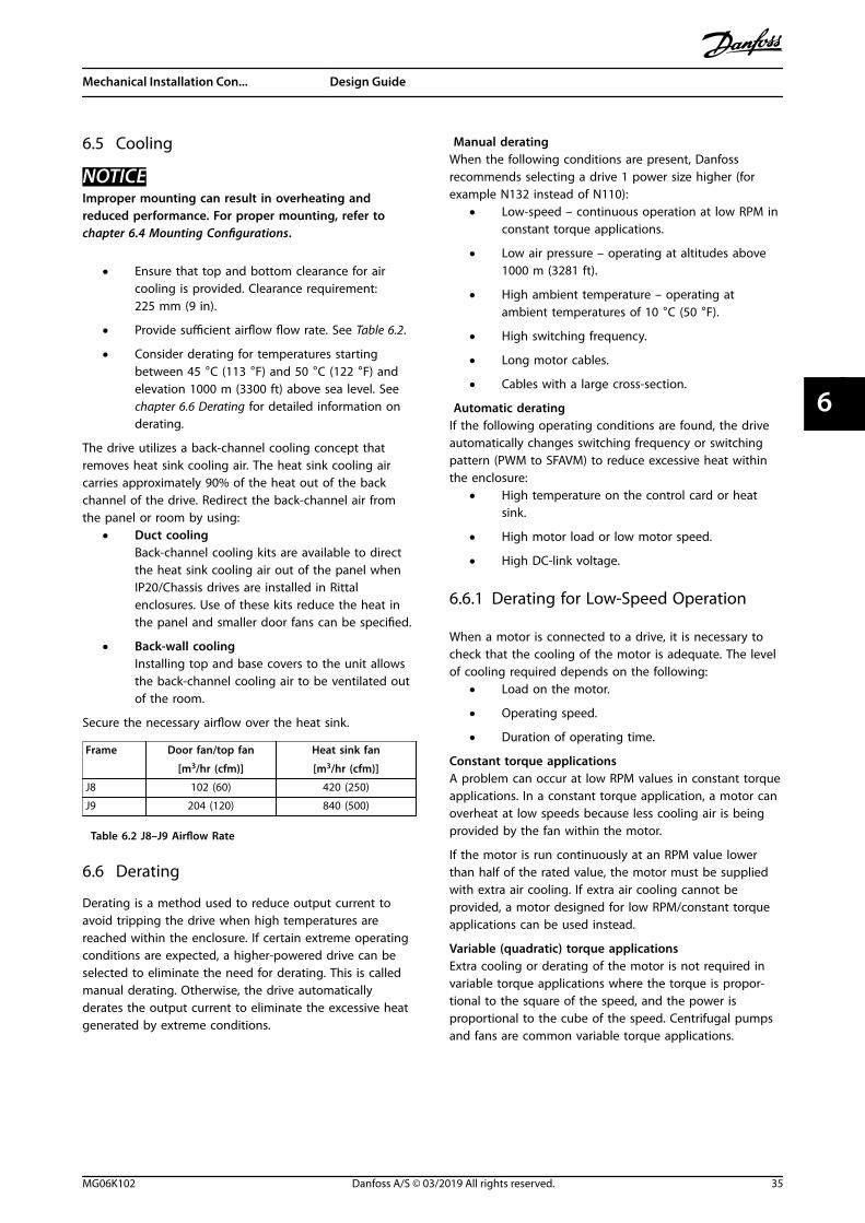
6.5 Cooling
NOTICEImproper mounting can result in overheating andreduced performance. For proper mounting, refer tochapter 6.4 Mounting Configurations.
• Ensure that top and bottom clearance for aircooling is provided. Clearance requirement:225 mm (9 in).
• Provide sufficient airflow flow rate. See Table 6.2.
• Consider derating for temperatures startingbetween 45 °C (113 °F) and 50 °C (122 °F) andelevation 1000 m (3300 ft) above sea level. Seechapter 6.6 Derating for detailed information onderating.
The drive utilizes a back-channel cooling concept thatremoves heat sink cooling air. The heat sink cooling aircarries approximately 90% of the heat out of the backchannel of the drive. Redirect the back-channel air fromthe panel or room by using:
• Duct coolingBack-channel cooling kits are available to directthe heat sink cooling air out of the panel whenIP20/Chassis drives are installed in Rittalenclosures. Use of these kits reduce the heat inthe panel and smaller door fans can be specified.
• Back-wall coolingInstalling top and base covers to the unit allowsthe back-channel cooling air to be ventilated outof the room.
Secure the necessary airflow over the heat sink.
Frame Door fan/top fan
[m3/hr (cfm)]
Heat sink fan
[m3/hr (cfm)]
J8 102 (60) 420 (250)
J9 204 (120) 840 (500)
Table 6.2 J8–J9 Airflow Rate
6.6 Derating
Derating is a method used to reduce output current toavoid tripping the drive when high temperatures arereached within the enclosure. If certain extreme operatingconditions are expected, a higher-powered drive can beselected to eliminate the need for derating. This is calledmanual derating. Otherwise, the drive automaticallyderates the output current to eliminate the excessive heatgenerated by extreme conditions.
Manual deratingWhen the following conditions are present, Danfossrecommends selecting a drive 1 power size higher (forexample N132 instead of N110):
• Low-speed – continuous operation at low RPM inconstant torque applications.
• Low air pressure – operating at altitudes above1000 m (3281 ft).
• High ambient temperature – operating atambient temperatures of 10 °C (50 °F).
• High switching frequency.
• Long motor cables.
• Cables with a large cross-section.
Automatic deratingIf the following operating conditions are found, the driveautomatically changes switching frequency or switchingpattern (PWM to SFAVM) to reduce excessive heat withinthe enclosure:
• High temperature on the control card or heatsink.
• High motor load or low motor speed.
• High DC-link voltage.
6.6.1 Derating for Low-Speed Operation
When a motor is connected to a drive, it is necessary tocheck that the cooling of the motor is adequate. The levelof cooling required depends on the following:
• Load on the motor.
• Operating speed.
• Duration of operating time.
Constant torque applicationsA problem can occur at low RPM values in constant torqueapplications. In a constant torque application, a motor canoverheat at low speeds because less cooling air is beingprovided by the fan within the motor.
If the motor is run continuously at an RPM value lowerthan half of the rated value, the motor must be suppliedwith extra air cooling. If extra air cooling cannot beprovided, a motor designed for low RPM/constant torqueapplications can be used instead.
Variable (quadratic) torque applicationsExtra cooling or derating of the motor is not required invariable torque applications where the torque is propor-tional to the square of the speed, and the power isproportional to the cube of the speed. Centrifugal pumpsand fans are common variable torque applications.
Mechanical Installation Con... Design Guide
MG06K102 Danfoss A/S © 03/2019 All rights reserved. 35
6 6

6.6.2 Derating for Altitude
The cooling capability of air is decreased at lower air pressure. No derating is necessary at or below 1000 m (3281 ft). Above1000 m (3281 ft), the ambient temperature (TAMB) or maximum output current (IMAX) should be derated. Refer toIllustration 6.2.
Max.Iout (%)at TAMB, MAX
Altitude (km)
HO NO
Tat 100% Iout
100%
96%
92%
0 K
-3 K
-6 K
1 km 2 km 3 km
-5 K
-8 K
-11 K
130B
T866
.10
AMB, MAX
Illustration 6.2 Derating of Output Current Based on Altitude at TAMB,MAX
Illustration 6.2 shows that at 41.7 °C (107 °F), 100% of the rated output current is available. At 45 °C (113 °F) (TAMB, MAX-3K), 91% of the rated output current is available.
Mechanical Installation Con... VLT® AutomationDrive FC 361
36 Danfoss A/S © 03/2019 All rights reserved. MG06K102
66
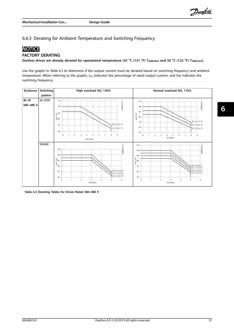
6.6.3 Derating for Ambient Temperature and Switching Frequency
NOTICEFACTORY DERATINGDanfoss drives are already derated for operational temperature (55 °C (131 °F) TAMB,MAX and 50 °C (122 °F) TAMB,AVG).
Use the graphs in Table 6.3 to determine if the output current must be derated based on switching frequency and ambienttemperature. When referring to the graphs, Iout indicates the percentage of rated output current, and fsw indicates theswitching frequency.
Enclosure Switchingpattern
High overload HO, 150% Normal overload NO, 110%
J8–J9380–480 V
60 AVM
130B
X473
.11
Iout
[%
]
fsw [kHz]
70
80
90
1
60
100
110
2 3 4 5 6 7 8 90
50 ˚C (122 ˚F)
55 ˚C (131 ˚F)
130B
X474
.11
70
80
90
1
60
100
110
2 3 4 5 6 7 8 9050
Iout
[%
]fsw [kHz]
45 ˚C (113 ˚F)
50 ˚C (122 ˚F)
55 ˚C (131 ˚F)
SFAVM
130B
X475
.11
Iout
[%
]
fsw [kHz]
70
80
90
60
100
110
2 4 60 31 5
45 ˚C (113 ˚F)50 ˚C (122 ˚F)55 ˚C (131 ˚F)
130B
X476
.11
Iout
[%
]
fsw [kHz]
70
80
90
60
100
110
2 4 6050
1 3 5
40 ˚C (104 ˚F)45 ˚C (113 ˚F)50 ˚C (122 ˚F)55 ˚C (131 ˚F)
Table 6.3 Derating Tables for Drives Rated 380–480 V
Mechanical Installation Con... Design Guide
MG06K102 Danfoss A/S © 03/2019 All rights reserved. 37
6 6
7 Electrical Installation Considerations
7.1 Safety Instructions
See chapter 2 Safety for general safety instructions.
WARNINGINDUCED VOLTAGEInduced voltage from output motor cables from differentdrives that are run together can charge equipmentcapacitors even with the equipment turned off andlocked out. Failure to run output motor cables separatelyor use shielded cables could result in death or seriousinjury.
• Run output motor cables separately or useshielded cables.
• Simultaneously lock out all the drives.
WARNINGSHOCK HAZARDThe drive can cause a DC current in the groundconductor and thus result in death or serious injury.
• When a residual current-operated protectivedevice (RCD) is used for protection againstelectrical shock, only an RCD of Type B isallowed on the supply side.
Failure to follow the recommendation means that theRCD cannot provide the intended protection.
Overcurrent protection• Extra protective equipment such as short-circuit
protection or motor thermal protection betweendrive and motor is required for applications withmultiple motors.
• Input fusing is required to provide short circuitand overcurrent protection. If fuses are notfactory-supplied, the installer must provide them.See maximum fuse ratings in chapter 7.5 Fusesand Circuit Breakers.
Wire type and ratings• All wiring must comply with local and national
regulations regarding cross-section and ambienttemperature requirements.
• Power connection wire recommendation:Minimum 75 °C (167 °F) rated copper wire.
See chapter 5.5 Cable Specifications for recommended wiresizes and types.
CAUTIONPROPERTY DAMAGEProtection against motor overload is not included in thedefault setting. To add this function, setparameter 1-90 Motor Thermal Protection to [ETR trip] or[ETR warning]. For the North American market, the ETRfunction provides class 20 motor overload protection inaccordance with NEC. Failure to set parameter 1-90 MotorThermal Protection to [ETR trip] or [ETR warning] meansthat motor overload protection is not provided and, ifthe motor overheats, property damage can occur.
Electrical Installation Con... VLT® AutomationDrive FC 361
38 Danfoss A/S © 03/2019 All rights reserved. MG06K102
77
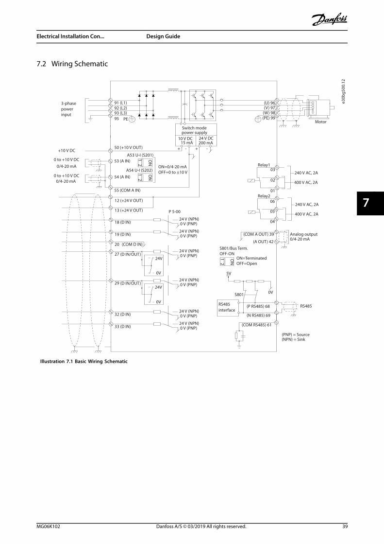
7.2 Wiring Schematic
e30b
g500
.12
91 (L1)92 (L2)93 (L3)
PE
50 (+10 V OUT)
53 (A IN)
54 (A IN)
55 (COM A IN)
0/4-20 mA
12 (+24 V OUT)
13 (+24 V OUT)
18 (D IN)
20 (COM D IN)
15 mA 200 mA
(U) 96(V) 97
(W) 98(PE) 99
(COM A OUT) 39
(A OUT) 420/4-20 mA
03
+10 V DC
0 to +10 V DC
0/4-20 mA
24 V DC
02
01
05
04
06240 V AC, 2A
24 V (NPN) 0 V (PNP)
0 V (PNP)24 V (NPN)
19 (D IN)
24 V (NPN) 0 V (PNP)27
24V
0V
(D IN/OUT)
0 V (PNP)24 V (NPN)
(D IN/OUT)
0V
24V29
24 V (NPN) 0 V (PNP)
0 V (PNP)24 V (NPN)
33 (D IN)
32 (D IN)
12
ON
A53 U-I (S201)
ON2
1A54 U-I (S202)ON=0/4-20 mAOFF=0 to ±10 V
95
400 V AC, 2AP 5-00
+ - + -
(P RS485) 68
(N RS485) 69
(COM RS485) 61
0V
5V
S801
RS485RS485
21 O
N
S801/Bus Term.OFF-ON
3-phasepowerinput
Switch modepower supply
Motor
Analog output
interface
Relay1
Relay2
ON=TerminatedOFF=Open
(NPN) = Sink(PNP) = Source
240 V AC, 2A
400 V AC, 2A
0 to +10 V DC
10 V DC
Illustration 7.1 Basic Wiring Schematic
Electrical Installation Con... Design Guide
MG06K102 Danfoss A/S © 03/2019 All rights reserved. 39
7 7
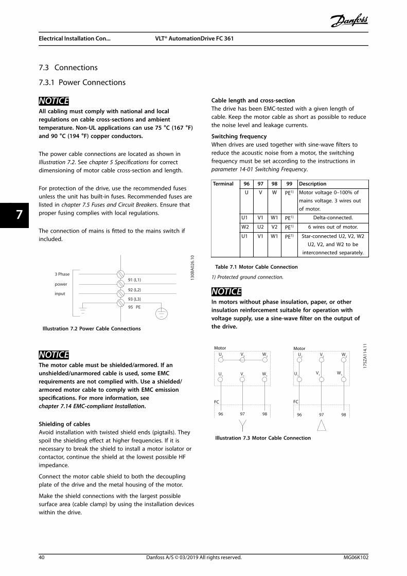
7.3 Connections
7.3.1 Power Connections
NOTICEAll cabling must comply with national and localregulations on cable cross-sections and ambienttemperature. Non-UL applications can use 75 °C (167 °F)and 90 °C (194 °F) copper conductors.
The power cable connections are located as shown inIllustration 7.2. See chapter 5 Specifications for correctdimensioning of motor cable cross-section and length.
For protection of the drive, use the recommended fusesunless the unit has built-in fuses. Recommended fuses arelisted in chapter 7.5 Fuses and Circuit Breakers. Ensure thatproper fusing complies with local regulations.
The connection of mains is fitted to the mains switch ifincluded.
3 Phase
power
input
130B
A02
6.10
91 (L1)
92 (L2)
93 (L3)
95 PE
Illustration 7.2 Power Cable Connections
NOTICEThe motor cable must be shielded/armored. If anunshielded/unarmored cable is used, some EMCrequirements are not complied with. Use a shielded/armored motor cable to comply with EMC emissionspecifications. For more information, seechapter 7.14 EMC-compliant Installation.
Shielding of cablesAvoid installation with twisted shield ends (pigtails). Theyspoil the shielding effect at higher frequencies. If it isnecessary to break the shield to install a motor isolator orcontactor, continue the shield at the lowest possible HFimpedance.
Connect the motor cable shield to both the decouplingplate of the drive and the metal housing of the motor.
Make the shield connections with the largest possiblesurface area (cable clamp) by using the installation deviceswithin the drive.
Cable length and cross-sectionThe drive has been EMC-tested with a given length ofcable. Keep the motor cable as short as possible to reducethe noise level and leakage currents.
Switching frequencyWhen drives are used together with sine-wave filters toreduce the acoustic noise from a motor, the switchingfrequency must be set according to the instructions inparameter 14-01 Switching Frequency.
Terminal 96 97 98 99 Description
U V W PE1) Motor voltage 0–100% ofmains voltage. 3 wires outof motor.
U1 V1 W1 PE1) Delta-connected.
W2 U2 V2 PE1) 6 wires out of motor.
U1 V1 W1 PE1) Star-connected U2, V2, W2U2, V2, and W2 to be
interconnected separately.
Table 7.1 Motor Cable Connection
1) Protected ground connection.
NOTICEIn motors without phase insulation, paper, or otherinsulation reinforcement suitable for operation withvoltage supply, use a sine-wave filter on the output ofthe drive.
U1
V1
W1
175Z
A11
4.11
96 97 98 96 97 98
FC FC
Motor MotorU
2V2
W2
U1
V1
W1
U2
V2
W2
Illustration 7.3 Motor Cable Connection
Electrical Installation Con... VLT® AutomationDrive FC 361
40 Danfoss A/S © 03/2019 All rights reserved. MG06K102
77
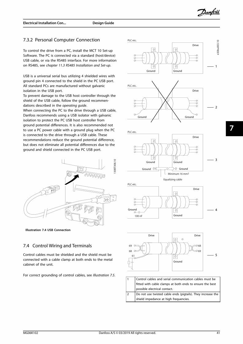
7.3.2 Personal Computer Connection
To control the drive from a PC, install the MCT 10 Set-upSoftware. The PC is connected via a standard (host/device)USB cable, or via the RS485 interface. For more informationon RS485, see chapter 11.3 RS485 Installation and Set-up.
USB is a universal serial bus utilizing 4 shielded wires withground pin 4 connected to the shield in the PC USB port.All standard PCs are manufactured without galvanicisolation in the USB port.To prevent damage to the USB host controller through theshield of the USB cable, follow the ground recommen-dations described in the operating guide.When connecting the PC to the drive through a USB cable,Danfoss recommends using a USB isolator with galvanicisolation to protect the PC USB host controller fromground potential differences. It is also recommended notto use a PC power cable with a ground plug when the PCis connected to the drive through a USB cable. Theserecommendations reduce the ground potential difference,but does not eliminate all potential differences due to theground and shield connected in the PC USB port.
130B
T308
.10
Illustration 7.4 USB Connection
7.4 Control Wiring and Terminals
Control cables must be shielded and the shield must beconnected with a cable clamp at both ends to the metalcabinet of the unit.
For correct grounding of control cables, see Illustration 7.5.
Drive
Ground
e30b
u003
.10
100 nF
69
68
61
68
69
PLC etc.
PLC etc.
PLC etc.
PLC etc.
Equalizing cable
Minimum 16 mm2
1
2
3
4
5
Drive
Ground
Drive
Ground
Drive
Ground
Drive
Ground
Ground
Ground
Ground Ground
Ground
Ground
Drive
1 Control cables and serial communication cables must befitted with cable clamps at both ends to ensure the bestpossible electrical contact.
2 Do not use twisted cable ends (pigtails). They increase theshield impedance at high frequencies.
Electrical Installation Con... Design Guide
MG06K102 Danfoss A/S © 03/2019 All rights reserved. 41
7 7

3 If the ground potential between the drive and the PLC isdifferent, electric noise can occur that disturbs the entiresystem. Fit an equalizing cable next to the control cable.
Minimum cable cross-section: 16 mm2 (6 AWG).
4 If long control cables are used, 50/60 Hz ground loops arepossible. Connect 1 end of the shield to ground via a 100nF capacitor (keeping leads short).
5 When using cables for serial communication, eliminatelow-frequency noise currents between 2 drives byconnecting 1 end of the shield to terminal 61. Thisterminal is connected to ground via an internal RC link.Use twisted-pair cables for reducing the differential modeinterference between the conductors.
Illustration 7.5 Grounding Examples
7.4.1 Control Cable Routing
Tie down and route all control wires. Remember toconnect the shields in a proper way to ensure optimumelectrical immunity.
• Isolate control wiring from high-power cables.
• When the drive is connected to a thermistor,ensure that the thermistor control wiring isshielded and reinforced/double insulated. A24 V DC supply voltage is recommended.
Fieldbus connectionConnections are made to the relevant options on thecontrol card. See the relevant fieldbus instruction. Thecable must be tied down and routed along with othercontrol wires inside the unit.
7.4.2 Control Terminals
Illustration 7.6 shows the removable drive connectors.Terminal functions and default settings are summarized inTable 7.2 – Table 7.4.
e30b
g501
.11
Illustration 7.6 Control Terminal Locations
12 13 18 19 27 29 32 33 20
39696861 42 50 53 54 55
e30b
g502
.11
1
2
3
1 Serial communication terminals
2 Digital input/output terminals
3 Analog input/output terminals
Illustration 7.7 Terminal Numbers Located on the Connectors
Electrical Installation Con... VLT® AutomationDrive FC 361
42 Danfoss A/S © 03/2019 All rights reserved. MG06K102
77

Terminal Parameter Defaultsetting
Description
61 – – Integrated RC-filter toconnect cable shieldif there are EMCproblems.
68 (+) Parametergroup 8-3* FCPort Settings
– RS485 interface. Aswitch (BUS TER.) isprovided on thecontrol card for busterminationresistance.
69 (-) Parametergroup 8-3* FCPort Settings
–
Table 7.2 Serial Communication Terminal Descriptions
Terminal Parameter Defaultsetting
Description
12, 13 – +24 V DC 24 V DC supplyvoltage for digitalinputs and externaltransducers.Maximum outputcurrent 200 mA for all24 V loads.
18 Parameter 5-10 Terminal 18Digital Input
[8] Start Digital inputs.
19 Parameter 5-11 Terminal 19Digital Input
[10]Reversing
32 Parameter 5-14 Terminal 32Digital Input
[0] Nooperation
33 Parameter 5-15 Terminal 33Digital Input
[0] Nooperation
27 Parameter 5-12 Terminal 27Digital Input
[2] Coastinverse
For digital input oroutput. Defaultsetting is input.
29 Parameter 5-13 Terminal 29Digital Input
[14] JOG
20 – – Common for digitalinputs and 0 Vpotential for 24 Vsupply.
Table 7.3 Digital Input/Output Terminal Descriptions
Terminal Parameter Defaultsetting
Description
39 – – Common for analogoutput.
42 Parameter 6-50 Terminal 42Output
[0] Nooperation
Programmable analogoutput. 0–20 mA or4–20 mA at a
maximum of 500 Ω.
50 – +10 V DC 10 V DC analogsupply voltage forpotentiometer orthermistor. 15 mAmaximum.
53 Parametergroup 6-1*Analog Input 1
Reference Analog input. Forvoltage or current.Switches A53 andA54 select mA or V.54 Parameter
group 6-2*Analog Input 2
Feedback
55 – – Common for analoginput.
Table 7.4 Analog Input/Output Terminal Descriptions
Relay terminals
RELAY 1 RELAY 2
01 02 03 04 05 06
130B
F156
.10
Illustration 7.8 Relay 1 and Relay 2 Terminals
• Relay 1 and relay 2. Location depends on driveconfiguration. See the operating guide.
• Terminals on built-in optional equipment. See theinstructions provided with the equipment option.
Terminal Parameter Defaultsetting
Description
01, 02, 03 Parameter 5-40 Function Relay[0]
[0] Nooperation
Form C relay output.For AC or DC voltageand resistive orinductive loads.04, 05, 06 Parameter 5-40
Function Relay[1]
[0] Nooperation
Table 7.5 Relay Terminal Descriptions
Electrical Installation Con... Design Guide
MG06K102 Danfoss A/S © 03/2019 All rights reserved. 43
7 7

7.5 Fuses and Circuit Breakers
Fuses ensure that possible damage to the drive is limited to damages inside the unit. To ensure compliance with EN 50178,use the recommended fuses as replacements. Use of fuses on the supply side is mandatory for IEC 60364 (CE) compliantinstallations.
J8–J9 recommended fusesType aR fuses are recommended for enclosures J8–J9. See Table 7.6.
Model 380–480 V
N90K ar-315
N110 ar-315
N132 ar-350
N160 ar-400
N200 ar-500
N250 ar-630
N315 ar-800
Table 7.6 J8–J9 Power/Semiconductor Fuse Sizes
Model Fuse Options
Bussman Littelfuse Littelfuse Bussmann Siba Ferraz-Shawmut
Ferraz-Shawmut(Europe)
N90K 170M2619 LA50QS300-4 L50S-300 FWH-300A 20 189 20.315 A50QS300-4 6,9URD31D08A0315
N110 170M2619 LA50QS300-4 L50S-300 FWH-300A 20 189 20.315 A50QS300-4 6,9URD31D08A0315
N132 170M2620 LA50QS350-4 L50S-350 FWH-350A 20 189 20.350 A50QS350-4 6,9URD31D08A0350
N160 170M2621 LA50QS400-4 L50S-400 FWH-400A 20 189 20.400 A50QS400-4 6,9URD31D08A0400
N200 170M4015 LA50QS500-4 L50S-500 FWH-500A 20 610 31.550 A50QS500-4 6,9URD31D08A0550
N250 170M4016 LA50QS600-4 L50S-600 FWH-600A 20 610 31.630 A50QS600-4 6,9URD31D08A0630
N315 170M4017 LA50QS800-4 L50S-800 FWH-800A 20 610 31.800 A50QS800-4 6,9URD32D08A0800
Table 7.7 J8–J9 Power/Semiconductor Fuse Options, 380–480 V
Bussmann Rating
LPJ-21/2SP 2.5 A, 600 V
Table 7.8 J8–J9 Space Heater Fuse Recommendation
NOTICEDISCONNECT SWITCHAll units ordered and supplied with a factory-installed disconnect switch require Class L branch circuit fusing to meetthe 100 kA SCCR for the drive. If a circuit breaker is used, the SCCR rating is 42 kA. The input voltage and power ratingof the drive determine the specific Class L fuse. The input voltage and power rating are found on the productnameplate. For more information regarding the nameplate, see chapter 6 Mechanical Installation Considerations.
Electrical Installation Con... VLT® AutomationDrive FC 361
44 Danfoss A/S © 03/2019 All rights reserved. MG06K102
77

7.6 Motor
Any 3-phase asynchronous standard motor can be usedwith a drive.
Terminal Function
96 U/T1
97 V/T2
98 W/T3
99 Ground
Table 7.9 Motor Cable Terminals Providing ClockwiseRotation (Factory Default)
The direction of rotation can be changed by switching 2phases in the motor cable, or by changing the setting ofparameter 4-10 Motor Speed Direction.
Motor rotation check can be performed usingparameter 1-28 Motor Rotation Check and following theconfiguration shown in Illustration 7.9.
175H
A03
6.11
U1 V1 W1
96 97 98
FC
MotorU2 V2 W2
U1 V1 W1
96 97 98
FC
MotorU2 V2 W2
Illustration 7.9 Changing Motor Rotation
7.6.1 Motor Thermal Protection
The electronic thermal relay in the drive has receivedapproval for single motor overload protection, whenparameter 1-90 Motor Thermal Protection is set for ETR Tripand parameter 1-24 Motor Current is set to the rated motorcurrent (see the motor nameplate).
7.6.2 Parallel Connection of Motors
The drive can control several parallel-connected motors.For different configurations of parallel-connected motors,see Illustration 7.10.
When using parallel motor connection, observe thefollowing points:
• Run applications with parallel motors in U/Fmode (volts per hertz).
• VVC+ mode can be used in some applications.
• Total current consumption of motors must notexceed the rated output current IINV for the drive.
• Problems can occur at start and at low RPM ifmotor sizes are widely different because therelatively high ohmic resistance in the stator of asmall motor demands a higher voltage at startand at low RPM.
• The electronic thermal relay (ETR) of the drivecannot be used as motor overload protection.Provide further motor overload protection byincluding thermistors in each motor winding orindividual thermal relays.
• When motors are connected in parallel,parameter 1-01 Motor Control Principle must be setto [0] U/f.
Electrical Installation Con... Design Guide
MG06K102 Danfoss A/S © 03/2019 All rights reserved. 45
7 7
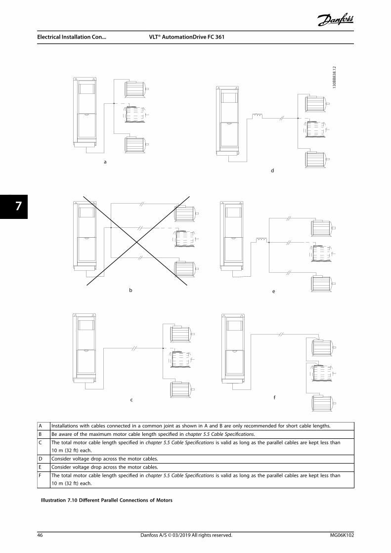
130B
B838
.12
a
b
c
d
e
f
A Installations with cables connected in a common joint as shown in A and B are only recommended for short cable lengths.
B Be aware of the maximum motor cable length specified in chapter 5.5 Cable Specifications.
C The total motor cable length specified in chapter 5.5 Cable Specifications is valid as long as the parallel cables are kept less than10 m (32 ft) each.
D Consider voltage drop across the motor cables.
E Consider voltage drop across the motor cables.
F The total motor cable length specified in chapter 5.5 Cable Specifications is valid as long as the parallel cables are kept less than10 m (32 ft) each.
Illustration 7.10 Different Parallel Connections of Motors
Electrical Installation Con... VLT® AutomationDrive FC 361
46 Danfoss A/S © 03/2019 All rights reserved. MG06K102
77

7.6.3 Motor Insulation
For motor cable lengths that are less than or equal to themaximum cable length listed in chapter 5.5 Cable Specifi-cations, use the motor insulation ratings shown inTable 7.10. If a motor has lower insulation rating, Danfossrecommends using a dU/dt or sine-wave filter.
Nominal mains voltage Motor insulation
UN≤420 V Standard ULL=1300 V
420 V<UN≤500 V Reinforced ULL=1600 V
500 V<UN≤600 V Reinforced ULL=1800 V
600 V<UN≤690 V Reinforced ULL=2000 V
Table 7.10 Motor Insulation Ratings
7.6.4 Motor Bearing Currents
To eliminate circulating bearing currents in all motorsinstalled with the drive, install NDE (non-drive end)insulated bearings. To minimize DE (drive end) bearing andshaft currents, ensure proper grounding of the drive,motor, driven machine, and motor to the driven machine.
Standard mitigation strategies:• Use an insulated bearing.
• Follow proper installation procedures.
- Ensure that the motor and load motorare aligned.
- Follow the EMC Installation guideline.
- Reinforce the PE so the high-frequencyimpedance is lower in the PE than theinput power leads.
- Provide a good high-frequencyconnection between the motor and thedrive. Use a shielded cable that has a360° connection in the motor and thedrive.
- Ensure that the impedance from thedrive to building ground is lower thanthe grounding impedance of themachine. This procedure can be difficultfor pumps.
- Make a direct ground connectionbetween the motor and load motor.
• Lower the IGBT switching frequency.
• Modify the inverter waveform, 60° AVM vs.SFAVM.
• Install a shaft grounding system or use anisolating coupling.
• Apply conductive lubrication.
• Use minimum speed settings if possible.
• Try to ensure that the mains voltage is balancedto ground. This procedure can be difficult for IT,TT, TN-CS, or grounded leg systems.
• Use a dU/dt or sine-wave filter.
7.7 Residual Current Devices (RCD) andInsulation Resistance Monitor (IRM)
Use RCD relays, multiple protective grounding, orgrounding as extra protection, provided they comply withlocal safety regulations.If a ground fault appears, a DC current can develop in thefaulty current. If RCD relays are used, local regulationsmust be observed. Relays must be suitable for protectionof 3-phase equipment with a bridge rectifier and for a briefdischarge on power-up. See chapter 7.8 Leakage Current formore details.
7.8 Leakage Current
Follow national and local codes regarding protectivegrounding of equipment where leakage current exceeds3.5 mA.Drive technology implies high-frequency switching at highpower. This high-frequency switching generates a leakagecurrent in the ground connection.
The ground leakage current is made up of several contri-butions and depends on various system configurations,including:
• RFI filtering.
• Motor cable length.
• Motor cable shielding.
• Drive power.
130B
B955
.12
a
b
Leakage current
Motor cable length
Illustration 7.11 Motor Cable Length and Power Size Influencethe Leakage Current. Power Size a > Power Size b.
The leakage current also depends on the line distortion.
Electrical Installation Con... Design Guide
MG06K102 Danfoss A/S © 03/2019 All rights reserved. 47
7 7
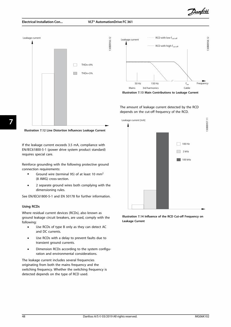
130B
B956
.12
THDv=0%
THDv=5%
Leakage current
Illustration 7.12 Line Distortion Influences Leakage Current
If the leakage current exceeds 3.5 mA, compliance withEN/IEC61800-5-1 (power drive system product standard)requires special care.
Reinforce grounding with the following protective groundconnection requirements:
• Ground wire (terminal 95) of at least 10 mm2
(8 AWG) cross-section.
• 2 separate ground wires both complying with thedimensioning rules.
See EN/IEC61800-5-1 and EN 50178 for further information.
Using RCDs
Where residual current devices (RCDs), also known asground leakage circuit breakers, are used, comply with thefollowing:
• Use RCDs of type B only as they can detect ACand DC currents.
• Use RCDs with a delay to prevent faults due totransient ground currents.
• Dimension RCDs according to the system configu-ration and environmental considerations.
The leakage current includes several frequenciesoriginating from both the mains frequency and theswitching frequency. Whether the switching frequency isdetected depends on the type of RCD used.
130B
B958
.12
f sw
Cable
150 Hz
3rd harmonics
50 Hz
Mains
RCD with low f cut-
RCD with high fcut-
Leakage current
Frequency
Illustration 7.13 Main Contributions to Leakage Current
The amount of leakage current detected by the RCDdepends on the cut-off frequency of the RCD.
130B
B957
.11
Leakage current [mA]
100 Hz
2 kHz
100 kHz
Illustration 7.14 Influence of the RCD Cut-off Frequency onLeakage Current
Electrical Installation Con... VLT® AutomationDrive FC 361
48 Danfoss A/S © 03/2019 All rights reserved. MG06K102
77
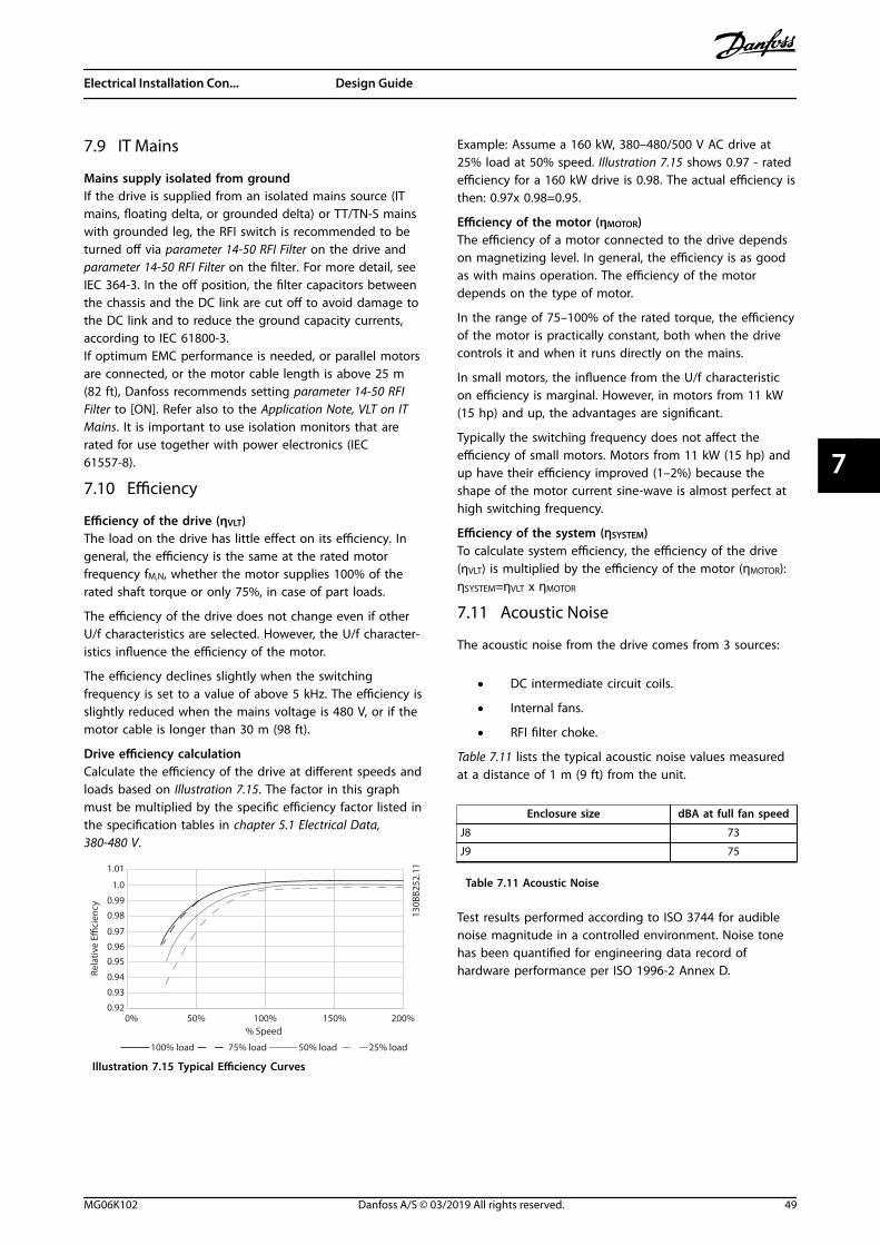
7.9 IT Mains
Mains supply isolated from groundIf the drive is supplied from an isolated mains source (ITmains, floating delta, or grounded delta) or TT/TN-S mainswith grounded leg, the RFI switch is recommended to beturned off via parameter 14-50 RFI Filter on the drive andparameter 14-50 RFI Filter on the filter. For more detail, seeIEC 364-3. In the off position, the filter capacitors betweenthe chassis and the DC link are cut off to avoid damage tothe DC link and to reduce the ground capacity currents,according to IEC 61800-3.If optimum EMC performance is needed, or parallel motorsare connected, or the motor cable length is above 25 m(82 ft), Danfoss recommends setting parameter 14-50 RFIFilter to [ON]. Refer also to the Application Note, VLT on ITMains. It is important to use isolation monitors that arerated for use together with power electronics (IEC61557-8).
7.10 Efficiency
Efficiency of the drive (ηVLT)The load on the drive has little effect on its efficiency. Ingeneral, the efficiency is the same at the rated motorfrequency fM,N, whether the motor supplies 100% of therated shaft torque or only 75%, in case of part loads.
The efficiency of the drive does not change even if otherU/f characteristics are selected. However, the U/f character-istics influence the efficiency of the motor.
The efficiency declines slightly when the switchingfrequency is set to a value of above 5 kHz. The efficiency isslightly reduced when the mains voltage is 480 V, or if themotor cable is longer than 30 m (98 ft).
Drive efficiency calculationCalculate the efficiency of the drive at different speeds andloads based on Illustration 7.15. The factor in this graphmust be multiplied by the specific efficiency factor listed inthe specification tables in chapter 5.1 Electrical Data,380-480 V.
1.0
0.990.98
0.97
0.960.95
0.93
0.920% 50% 100% 200%
0.94Rela
tive
Eci
ency
130B
B252
.111.01
150%% Speed
100% load 75% load 50% load 25% load
Illustration 7.15 Typical Efficiency Curves
Example: Assume a 160 kW, 380–480/500 V AC drive at25% load at 50% speed. Illustration 7.15 shows 0.97 - ratedefficiency for a 160 kW drive is 0.98. The actual efficiency isthen: 0.97x 0.98=0.95.
Efficiency of the motor (ηMOTOR)The efficiency of a motor connected to the drive dependson magnetizing level. In general, the efficiency is as goodas with mains operation. The efficiency of the motordepends on the type of motor.
In the range of 75–100% of the rated torque, the efficiencyof the motor is practically constant, both when the drivecontrols it and when it runs directly on the mains.
In small motors, the influence from the U/f characteristicon efficiency is marginal. However, in motors from 11 kW(15 hp) and up, the advantages are significant.
Typically the switching frequency does not affect theefficiency of small motors. Motors from 11 kW (15 hp) andup have their efficiency improved (1–2%) because theshape of the motor current sine-wave is almost perfect athigh switching frequency.
Efficiency of the system (ηSYSTEM)To calculate system efficiency, the efficiency of the drive(ηVLT) is multiplied by the efficiency of the motor (ηMOTOR):ηSYSTEM=ηVLT x ηMOTOR
7.11 Acoustic Noise
The acoustic noise from the drive comes from 3 sources:
• DC intermediate circuit coils.
• Internal fans.
• RFI filter choke.
Table 7.11 lists the typical acoustic noise values measuredat a distance of 1 m (9 ft) from the unit.
Enclosure size dBA at full fan speed
J8 73
J9 75
Table 7.11 Acoustic Noise
Test results performed according to ISO 3744 for audiblenoise magnitude in a controlled environment. Noise tonehas been quantified for engineering data record ofhardware performance per ISO 1996-2 Annex D.
Electrical Installation Con... Design Guide
MG06K102 Danfoss A/S © 03/2019 All rights reserved. 49
7 7
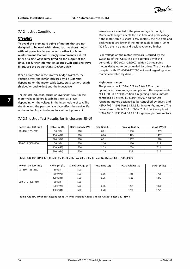
7.12 dU/dt Conditions
NOTICETo avoid the premature aging of motors that are notdesigned to be used with drives, such as those motorswithout phase insulation paper or other insulationreinforcement, Danfoss strongly recommends a dU/dtfilter or a sine-wave filter fitted on the output of thedrive. For further information about dU/dt and sine-wavefilters, see the Output Filters Design Guide.
When a transistor in the inverter bridge switches, thevoltage across the motor increases by a dU/dt ratiodepending on the motor cable (type, cross-section, lengthshielded or unshielded) and the inductance.
The natural induction causes an overshoot UPEAK in themotor voltage before it stabilizes itself at a leveldepending on the voltage in the intermediate circuit. Therise time and the peak voltage UPEAK affect the service lifeof the motor. In particular, motors without phase coil
insulation are affected if the peak voltage is too high.Motor cable length affects the rise time and peak voltage.If the motor cable is short (a few meters), the rise time andpeak voltage are lower. If the motor cable is long (100 m(328 ft)), the rise time and peak voltage are higher.
Peak voltage on the motor terminals is caused by theswitching of the IGBTs. The drive complies with thedemands of IEC 60034-25:2007 edition 2.0 regardingmotors designed to be controlled by drives. The drive alsocomplies with IEC 60034-17:2006 edition 4 regarding Normmotors controlled by drives.
High-power rangeThe power sizes in Table 7.12 to Table 7.13 at theappropriate mains voltages comply with the requirementsof IEC 60034-17:2006 edition 4 regarding normal motorscontrolled by drives, IEC 60034-25:2007 edition 2.0regarding motors designed to be controlled by drives, andNEMA MG 1-1998 Part 31.4.4.2 for inverter-fed motors. Thepower sizes in Table 7.12 to Table 7.13 do not comply withNEMA MG 1-1998 Part 30.2.2.8 for general purpose motors.
7.12.1 dU/dt Test Results for Enclosures J8–J9
Power size [kW (hp)] Cable [m (ft)] Mains voltage [V] Rise time [µs] Peak voltage [V] dU/dt [V/µs]
90–160 (125–250) 30 (98) 500 0.71 1180 1339
150 (492) 500 0.76 1423 1497
300 (984) 500 0.91 1557 1370
200–315 (300–450) 30 (98) 500 1.10 1116 815
150 (492) 500 2.53 1028 321
300 (984) 500 1.29 835 517
Table 7.12 IEC dU/dt Test Results for J8–J9 with Unshielded Cables and No Output Filter, 380–480 V
Power size [kW (hp)] Cable [m (ft)] Mains voltage [V] Rise time [µs] Peak voltage [V] dU/dt [V/µs]
90–160 (125–250) 30 (98) 500 – – –
150 (492) 500 0.66 1418 1725
300 (984) 500 0.96 1530 1277
200–315 (300–450) 30 (98) 500 – – –
150 (492) 500 0.56 1261 1820
300 (984) 500 0.78 1278 1295
Table 7.13 IEC dU/dt Test Results for J8–J9 with Shielded Cables and No Output Filter, 380–480 V
Electrical Installation Con... VLT® AutomationDrive FC 361
50 Danfoss A/S © 03/2019 All rights reserved. MG06K102
77

7.13 Electromagnetic Compatibility (EMC) Overview
Electrical devices both generate interference and are affected by interference from other generated sources. The electro-magnetic compatibility (EMC) of these effects depends on the power and the harmonic characteristics of the devices.
Uncontrolled interaction between electrical devices in a system can degrade compatibility and impair reliable operation.Interference takes the form of the following:
• Electrostatic discharges.
• Rapid voltage fluctuations.
• High-frequency interference.
Electrical interference is most commonly found at frequencies in the range 150 kHz to 30 MHz. Airborne interference fromthe drive system in the range 30 MHz to 1 GHz is generated from the inverter, motor cable, and the motor.
Capacitive currents in the motor cable, coupled with a high dU/dt from the motor voltage, generate leakage currents. SeeIllustration 7.16. Shielded motor cables have higher capacitance between the phase wires and the shield, and again betweenthe shield and ground. This added cable capacitance, along with other parasitic capacitance and motor inductance, changesthe electromagnetic emission signature produced by the unit. The change in electromagnetic emission signature occursmainly in emissions less than 5 MHz. Most of the leakage current (I1) is carried back to the unit through the PE (I3), leavingonly a small electromagnetic field (I4) from the shielded motor cable. The shield reduces the radiated interference butincreases the low-frequency interference on the mains.
1
2
z
z
z
L1
L2
L3
PE
U
V
W
CS
I2
I1
I3
I4
CS CS CS
CS
I4
CSz PE
3 4 5 617
5ZA
062.
12
1 Ground wire Cs Possible shunt parasitic capacitance paths (varies with differentinstallations)
2 Shield I1 Common-mode leakage current
3 AC mains supply I2 Shielded motor cable
4 Drive I3 Safety ground (4th conductor in motor cables)
5 Shielded motor cable I4 Unintended common-mode current
6 Motor – –
Illustration 7.16 Electric Model Showing Possible Leakage Currents
Electrical Installation Con... Design Guide
MG06K102 Danfoss A/S © 03/2019 All rights reserved. 51
7 7

7.13.1 EMC Test Results
The following test results have been obtained using a drive (with options if relevant), a shielded control cable, a control boxwith potentiometer, a motor, and motor shielded cable.
RFI filter type Conducted emission Radiated emission
Standards andrequirements
EN 55011 Class BHousing,
trades, andlight
industries
Class Agroup 1
Industrialenvironment
Class Agroup 2
Industrialenvironment
Class BHousing, trades,
and lightindustries
Class Agroup 1
Industrialenvironment
Class Agroup 2
Industrialenvironment
EN/IEC 61800-3 Category C1First
environmentHome and
office
Category C2First
environmentHome and
office
Category C3Second
environmentIndustrial
Category C1First
environmentHome and office
Category C2First environmentHome and office
Category C3First
environmentHome and
office
FC 361 90–315 kW380–480 V
No No 150 m(492 ft)
No No Yes
Table 7.14 EMC Test Results (Emission and Immunity)
7.13.2 Emission Requirements
According to the EMC product standard for adjustable speed drives EN/IEC 61800-3:2004, the EMC requirements depend onthe environment in which the drive is installed. These environments along with the mains voltage supply requirements aredefined in Table 7.15.
The drives comply with EMC requirements described in IEC/EN 61800-3 (2004)+AM1 (2011), category C3, for equipmenthaving greater than 100 A per-phase current draw, installed in the 2nd environment. Compliance testing is performed with a150 m (492 ft) shielded motor cable.
Category(EN 61800-3)
Definition Conducted emission(EN 55011)
C1 First environment (home and office) with a supply voltage less than 1000 V. Class B
C2 First environment (home and office) with a supply voltage less than 1000 V, whichis not plug-in or movable and where a professional is intended to be used toinstall or commission the system.
Class A Group 1
C3 Second environment (industrial) with a supply voltage lower than 1000 V. Class A Group 2
C4 Second environment with the following:
• Supply voltage equal to or above 1000 V.
• Rated current equal to or above 400 A.
• Intended for use in complex systems.
No limit line.An EMC plan must be made.
Table 7.15 Emission Requirements
When the generic emission standards are used, the drives are required to comply with Table 7.16.
Environment Generic standard Conducted emission requirementaccording to EN 55011 limits
First environment(home and office)
EN/IEC 61000-6-3 Emission standard for residential, commercial,and light industrial environments.
Class B
Second environment(industrial environment)
EN/IEC 61000-6-4 Emission standard for industrial environments. Class A Group 1
Table 7.16 Generic Emission Standard Limits
Electrical Installation Con... VLT® AutomationDrive FC 361
52 Danfoss A/S © 03/2019 All rights reserved. MG06K102
77

7.13.3 Immunity Requirements
The immunity requirements for drives depend on the installation environment. The requirements for the industrialenvironment are higher than the requirements for the home and office environment. All Danfoss drives comply with therequirements for both the industrial and the home/office environment.
To document immunity against burst transient, the following immunity tests have been performed on a drive (with optionsif relevant), a shielded control cable, and a control box with potentiometer, motor cable, and motor. The tests wereperformed in accordance with the following basic standards. For more details, see Table 7.17.
• EN 61000-4-2 (IEC 61000-4-2): Electrostatic discharges (ESD): Simulation of electrostatic discharges from humanbeings.
• EN 61000-4-3 (IEC 61000-4-3): Incoming electromagnetic field radiation, amplitude modulated simulation of theeffects of radar, radio communication equipment, and mobile communications equipment.
• EN 61000-4-4 (IEC 61000-4-4): Burst transients: Simulation of interference brought about by switching a contactor,relay, or similar devices.
• EN 61000-4-5 (IEC 61000-4-5): Surge transients: Simulation of transients brought about by lightning strikes nearinstallations.
• EN 61000-4-6 (IEC 61000-4-6): RF common mode: Simulation of the effect from radio-transmission equipmentjoined by connection cables.
Basic standard BurstIEC 61000-4-4
SurgeIEC 61000-4-5
ESDIEC
61000-4-2
Radiatedelectro-magnetic field
IEC 61000-4-3
RF commonmode voltageIEC 61000-4-6
Acceptance criterion B B B A A
Line 4 kV CM 2 kV/2 Ω DM
4 kV/12 Ω CM
– – 10 VRMS
Motor 4 kV CM 4 kV/2 Ω1) – – 10 VRMS
Control wires 2 kV CM 2 kV/2 Ω1) – – 10 VRMS
Standard bus 2 kV CM 2 kV/2 Ω1) – – 10 VRMS
Relay wires 2 kV CM 2 kV/2 Ω1) – – 10 VRMS
Application/fieldbus options 2 kV CM 2 kV/2 Ω1) – – 10 VRMS
LCP cable 2 kV CM 2 kV/2 Ω1) – – 10 VRMS
External 24 V DC 2 V CM 0.5 kV/2 Ω DM
1 kV/12 Ω CM
– – 10 VRMS
Enclosure – – 8 kV AD6 kV CD
10 V/m –
Table 7.17 EMC Immunity Form, Voltage Range: 380–480
1) Injection on cable shield.AD: air discharge; CD: contact discharge; CM: common mode; DM: differential mode.
Electrical Installation Con... Design Guide
MG06K102 Danfoss A/S © 03/2019 All rights reserved. 53
7 7
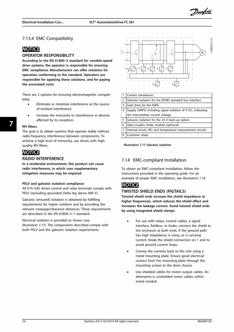
7.13.4 EMC Compatibility
NOTICEOPERATOR RESPONSIBILITYAccording to the EN 61800–3 standard for variable-speeddrive systems, the operator is responsible for ensuringEMC compliance. Manufacturers can offer solutions foroperation conforming to the standard. Operators areresponsible for applying these solutions, and for payingthe associated costs.
There are 2 options for ensuring electromagnetic compati-bility.
• Eliminate or minimize interference at the sourceof emitted interference.
• Increase the immunity to interference in devicesaffected by its reception.
RFI filtersThe goal is to obtain systems that operate stably withoutradio frequency interference between components. Toachieve a high level of immunity, use drives with high-quality RFI filters.
NOTICERADIO INTERFERENCEIn a residential environment, this product can causeradio interference, in which case supplementarymitigation measures may be required.
PELV and galvanic isolation complianceAll E1h–E4h drives control and relay terminals comply withPELV (excluding grounded Delta leg above 400 V).
Galvanic (ensured) isolation is obtained by fulfillingrequirements for higher isolation and by providing therelevant creepage/clearance distances. These requirementsare described in the EN 61800–5–1 standard.
Electrical isolation is provided as shown (seeIllustration 7.17). The components described comply withboth PELV and the galvanic isolation requirements.
130B
X514
.10
4
1
37 68
25
M
1 Current transducers
2 Galvanic isolation for the RS485 standard bus interface
3 Gate drive for the IGBTs
4 Supply (SMPS) including signal isolation of V DC, indicatingthe intermediate current voltage
5 Galvanic isolation for the 24 V back-up option
6 Opto-coupler, brake module (optional)
7 Internal inrush, RFI, and temperature measurement circuits
8 Customer relays
Illustration 7.17 Galvanic Isolation
7.14 EMC-compliant Installation
To obtain an EMC-compliant installation, follow theinstructions provided in the operating guide. For anexample of proper EMC installation, see Illustration 7.18.
NOTICETWISTED SHIELD ENDS (PIGTAILS)Twisted shield ends increase the shield impedance athigher frequencies, which reduces the shield effect andincreases the leakage current. Avoid twisted shield endsby using integrated shield clamps.
• For use with relays, control cables, a signalinterface, fieldbus, or brake, connect the shield tothe enclosure at both ends. If the ground pathhas high impedance, is noisy, or is carryingcurrent, break the shield connection on 1 end toavoid ground current loops.
• Convey the currents back to the unit using ametal mounting plate. Ensure good electricalcontact from the mounting plate through themounting screws to the drive chassis.
• Use shielded cables for motor output cables. Analternative is unshielded motor cables withinmetal conduit.
Electrical Installation Con... VLT® AutomationDrive FC 361
54 Danfoss A/S © 03/2019 All rights reserved. MG06K102
77
NOTICESHIELDED CABLESIf shielded cables or metal conduits are not used, theunit and the installation do not meet regulatory limitson radio frequency (RF) emission levels.
• Ensure that motor and brake cables are as shortas possible to reduce the interference level fromthe entire system.
• Avoid placing cables with a sensitive signal levelalongside motor and brake cables.
• For communication and command/control lines,follow the particular communication protocolstandards. For example, USB must use shieldedcables, but RS485/ethernet can use shielded UTPor unshielded UTP cables.
• Ensure that all control terminal connections arePELV.
NOTICEEMC INTERFERENCEUse shielded cables for motor and control wiring. Makesure to separate mains input, motor, and control cablesfrom one another. Failure to isolate these cables canresult in unintended behavior or reduced performance.Minimum 200 mm (7.9 in) clearance between mainsinput, motor, and control cables are required.
NOTICEINSTALLATION AT HIGH ALTITUDEThere is a risk of overvoltage. Isolation betweencomponents and critical parts could be insufficient andnot comply with PELV requirements. Reduce the risk ofovervoltage by using external protective devices orgalvanic isolation.For installations above 2000 m (6500 ft) altitude, contactDanfoss regarding PELV compliance.
Electrical Installation Con... Design Guide
MG06K102 Danfoss A/S © 03/2019 All rights reserved. 55
7 7

NOTICEPELV COMPLIANCEPrevent electric shock by using protective extra lowvoltage (PELV) electrical supply and complying with localand national PELV regulations.
e30b
f228
.11
L1L2L3PE
PE
u
v
w
2
1
3
5
16
17
18
14
12
8
7
10
9
4
11
13
4
6
15
90
4
1 PLC 10 Mains cable (unshielded)
2 Minimum 16 mm2 (6 AWG) equalizing cable 11 Output contactor
3 Control cables 12 Cable insulation stripped
4 Minimum 200 mm (7.9 in) between control cables, motorcables, and mains cables
13 Common ground busbar. Follow local and nationalrequirements for cabinet grounding
5 Mains supply 14 Brake resistor
6 Bare (unpainted) surface 15 Metal box
7 Star washers 16 Connection to motor
8 Brake cable (shielded) 17 Motor
9 Motor cable (shielded) 18 EMC cable gland
Illustration 7.18 Example of Proper EMC Installation
Electrical Installation Con... VLT® AutomationDrive FC 361
56 Danfoss A/S © 03/2019 All rights reserved. MG06K102
77
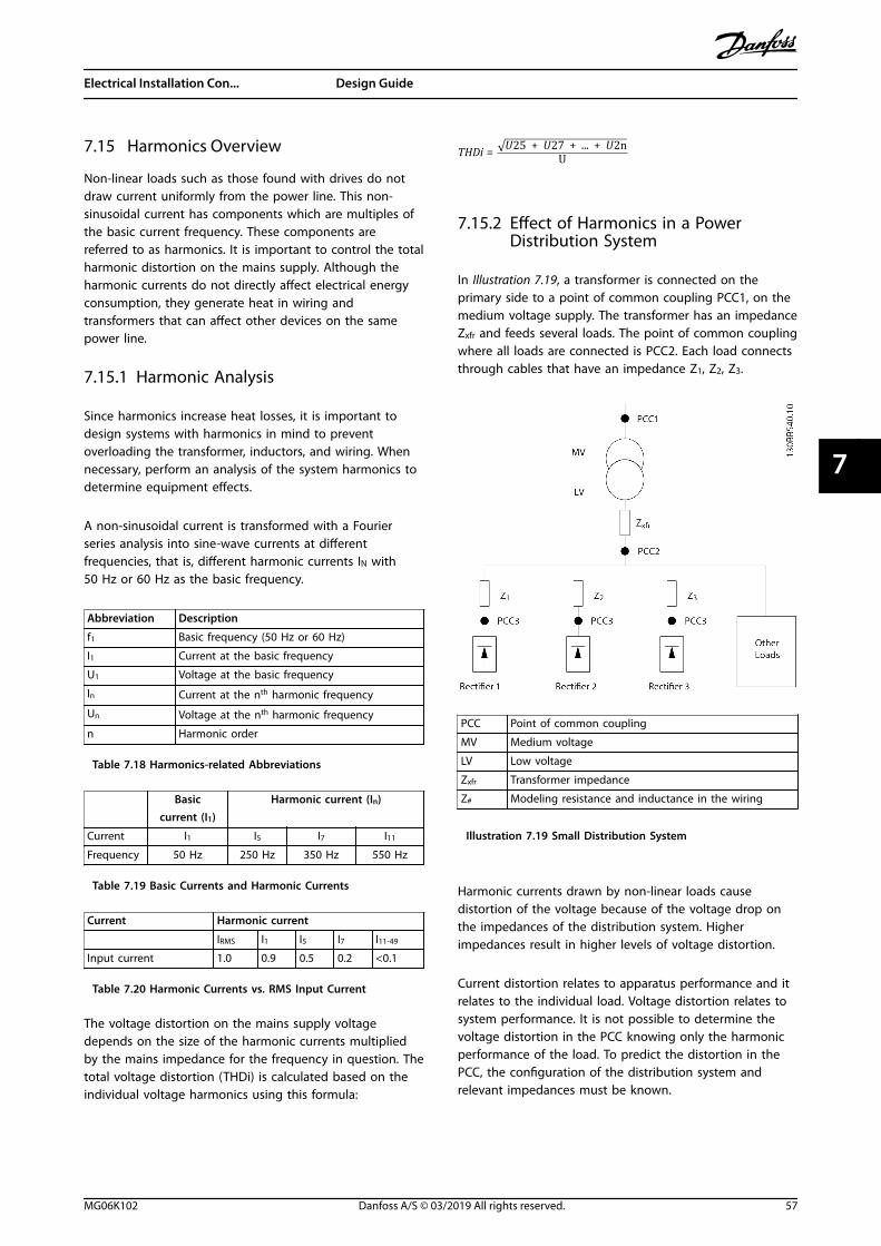
7.15 Harmonics Overview
Non-linear loads such as those found with drives do notdraw current uniformly from the power line. This non-sinusoidal current has components which are multiples ofthe basic current frequency. These components arereferred to as harmonics. It is important to control the totalharmonic distortion on the mains supply. Although theharmonic currents do not directly affect electrical energyconsumption, they generate heat in wiring andtransformers that can affect other devices on the samepower line.
7.15.1 Harmonic Analysis
Since harmonics increase heat losses, it is important todesign systems with harmonics in mind to preventoverloading the transformer, inductors, and wiring. Whennecessary, perform an analysis of the system harmonics todetermine equipment effects.
A non-sinusoidal current is transformed with a Fourierseries analysis into sine-wave currents at differentfrequencies, that is, different harmonic currents IN with50 Hz or 60 Hz as the basic frequency.
Abbreviation Description
f1 Basic frequency (50 Hz or 60 Hz)
I1 Current at the basic frequency
U1 Voltage at the basic frequency
In Current at the nth harmonic frequency
Un Voltage at the nth harmonic frequency
n Harmonic order
Table 7.18 Harmonics-related Abbreviations
Basiccurrent (I1)
Harmonic current (In)
Current I1 I5 I7 I11
Frequency 50 Hz 250 Hz 350 Hz 550 Hz
Table 7.19 Basic Currents and Harmonic Currents
Current Harmonic current
IRMS I1 I5 I7 I11-49
Input current 1.0 0.9 0.5 0.2 <0.1
Table 7.20 Harmonic Currents vs. RMS Input Current
The voltage distortion on the mains supply voltagedepends on the size of the harmonic currents multipliedby the mains impedance for the frequency in question. Thetotal voltage distortion (THDi) is calculated based on theindividual voltage harmonics using this formula:
THDi = U25 + U27 + ... + U2nU
7.15.2 Effect of Harmonics in a PowerDistribution System
In Illustration 7.19, a transformer is connected on theprimary side to a point of common coupling PCC1, on themedium voltage supply. The transformer has an impedanceZxfr and feeds several loads. The point of common couplingwhere all loads are connected is PCC2. Each load connectsthrough cables that have an impedance Z1, Z2, Z3.
PCC Point of common coupling
MV Medium voltage
LV Low voltage
Zxfr Transformer impedance
Z# Modeling resistance and inductance in the wiring
Illustration 7.19 Small Distribution System
Harmonic currents drawn by non-linear loads causedistortion of the voltage because of the voltage drop onthe impedances of the distribution system. Higherimpedances result in higher levels of voltage distortion.
Current distortion relates to apparatus performance and itrelates to the individual load. Voltage distortion relates tosystem performance. It is not possible to determine thevoltage distortion in the PCC knowing only the harmonicperformance of the load. To predict the distortion in thePCC, the configuration of the distribution system andrelevant impedances must be known.
Electrical Installation Con... Design Guide
MG06K102 Danfoss A/S © 03/2019 All rights reserved. 57
7 7

A commonly used term for describing the impedance of a grid is the short circuit ratio Rsce, where Rsce is defined as theratio between the short circuit apparent power of the supply at the PCC (Ssc) and the rated apparent power of the load.
(Sequ).Rsce =SscSequ
where Ssc = U2Zsupply
and Sequ = U × Iequ
Negative effects of harmonics• Harmonic currents contribute to system losses (in cabling and transformer).
• Harmonic voltage distortion causes disturbance to other loads and increases losses in other loads.
7.15.3 IEC Harmonic Standards
In most of Europe, the basis for the objective assessment of the quality of mains power is the Electromagnetic Compatibilityof Devices Act (EMVG). Compliance with these regulations ensures that all devices and networks connected to electricaldistribution systems fulfill their intended purpose without generating problems.
Standard Definition
EN 61000-2-2, EN 61000-2-4, EN 50160 Define the mains voltage limits required for public and industrial power grids.
EN 61000-3-2, EN 61000-3-12 Regulate mains interference generated by connected devices in lower current products.
EN 50178 Monitors electronic equipment for use in power installations.
Table 7.21 EN Design Standards for Mains Power Quality
There are 2 European standards that address harmonics in the frequency range from 0 Hz to 9 kHz:
EN 61000–2–2 (Compatibility Levels for Low-Frequency Conducted Disturbances and Signaling in Public Low-VoltagePower Supply SystemsThe EN 61000–2–2 standard states the requirements for compatibility levels for PCC (point of common coupling) of low-voltage AC systems on a public supply network. Limits are specified only for harmonic voltage and total harmonic distortionof the voltage. EN 61000–2–2 does not define limits for harmonic currents. In situations where the total harmonic distortionTHD(V)=8%, PCC limits are identical to those limits specified in the EN 61000–2–4 Class 2.
EN 61000–2–4 (Compatibility Levels for Low-Frequency Conducted Disturbances and Signaling in Industrial Plants)The EN 61000–2–4 standard states the requirements for compatibility levels in industrial and private networks. The standardfurther defines the following 3 classes of electromagnetic environments:
• Class 1 relates to compatibility levels that are less than the public supply network, which affects equipmentsensitive to disturbances (lab equipment, some automation equipment, and certain protection devices).
• Class 2 relates to compatibility levels that are equal to the public supply network. The class applies to PCCs on thepublic supply network and to IPCs (internal points of coupling) on industrial or other private supply networks. Anyequipment designed for operation on a public supply network is allowed in this class.
• Class 3 relates to compatibility levels greater than the public supply network. This class applies only to IPCs inindustrial environments. Use this class where the following equipment is found:
- Large drives.
- Welding machines.
- Large motors starting frequently.
- Loads that change quickly.
Typically, a class cannot be defined ahead of time without considering the intended equipment and processes to be used inthe environment. Drives observe the limits of Class 3 under typical supply system conditions (RSC>10 or Vk Line<10%).
Electrical Installation Con... VLT® AutomationDrive FC 361
58 Danfoss A/S © 03/2019 All rights reserved. MG06K102
77

Harmonic order (h) Class 1 (Vh%) Class 2 (Vh%) Class 3 (Vh%)
5 3 6 8
7 3 5 7
11 3 3.5 5
13 3 3 4.5
17 2 2 4
17˂h≤49 2.27 x (17/h) – 0.27 2.27 x (17/h) – 0.27 4.5 x (17/h) – 0.5
Table 7.22 Compatibility Levels for Harmonics
Class 1 Class 2 Class 3
THDv 5% 8% 10%
Table 7.23 Compatibility Levels for the Total Harmonic Voltage Distortion THDv
7.15.4 Harmonic Compliance
Danfoss drives comply with the following standards:• IEC61000-2-4.
• IEC61000-3-4.
• G5/4.
Electrical Installation Con... Design Guide
MG06K102 Danfoss A/S © 03/2019 All rights reserved. 59
7 7
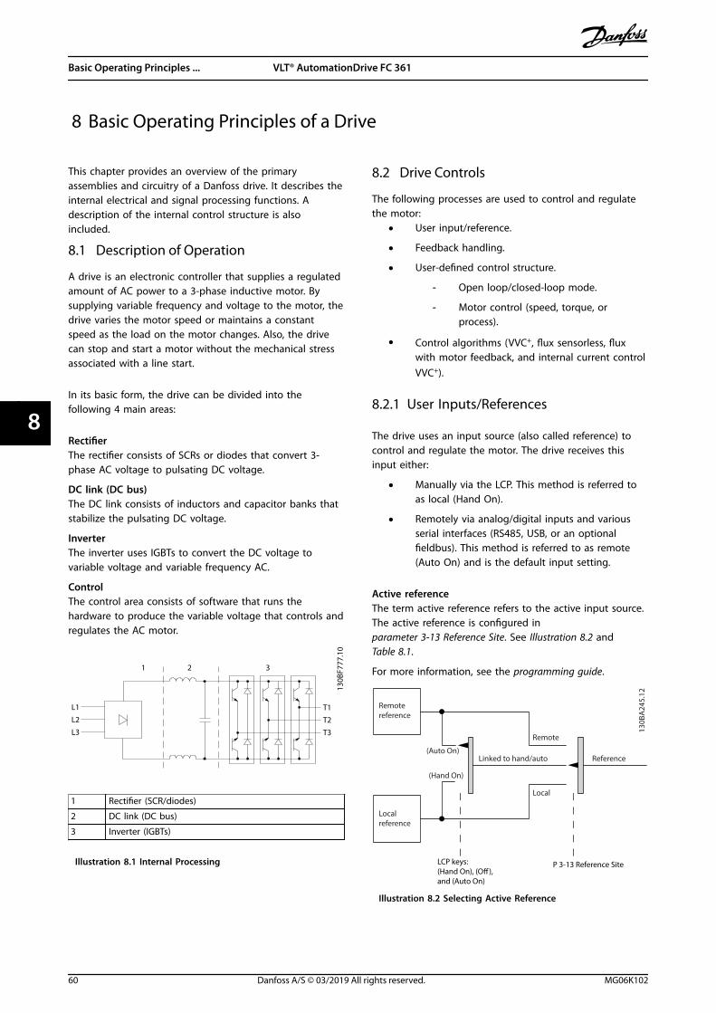
8 Basic Operating Principles of a Drive
This chapter provides an overview of the primaryassemblies and circuitry of a Danfoss drive. It describes theinternal electrical and signal processing functions. Adescription of the internal control structure is alsoincluded.
8.1 Description of Operation
A drive is an electronic controller that supplies a regulatedamount of AC power to a 3-phase inductive motor. Bysupplying variable frequency and voltage to the motor, thedrive varies the motor speed or maintains a constantspeed as the load on the motor changes. Also, the drivecan stop and start a motor without the mechanical stressassociated with a line start.
In its basic form, the drive can be divided into thefollowing 4 main areas:
RectifierThe rectifier consists of SCRs or diodes that convert 3-phase AC voltage to pulsating DC voltage.
DC link (DC bus)The DC link consists of inductors and capacitor banks thatstabilize the pulsating DC voltage.
InverterThe inverter uses IGBTs to convert the DC voltage tovariable voltage and variable frequency AC.
ControlThe control area consists of software that runs thehardware to produce the variable voltage that controls andregulates the AC motor.
L1
L2
L3
T1
T2
T3
1 2 3
130B
F777
.10
1 Rectifier (SCR/diodes)
2 DC link (DC bus)
3 Inverter (IGBTs)
Illustration 8.1 Internal Processing
8.2 Drive Controls
The following processes are used to control and regulatethe motor:
• User input/reference.
• Feedback handling.
• User-defined control structure.
- Open loop/closed-loop mode.
- Motor control (speed, torque, orprocess).
• Control algorithms (VVC+, flux sensorless, fluxwith motor feedback, and internal current controlVVC+).
8.2.1 User Inputs/References
The drive uses an input source (also called reference) tocontrol and regulate the motor. The drive receives thisinput either:
• Manually via the LCP. This method is referred toas local (Hand On).
• Remotely via analog/digital inputs and variousserial interfaces (RS485, USB, or an optionalfieldbus). This method is referred to as remote(Auto On) and is the default input setting.
Active referenceThe term active reference refers to the active input source.The active reference is configured inparameter 3-13 Reference Site. See Illustration 8.2 andTable 8.1.
For more information, see the programming guide.
Remotereference
Localreference
(Auto On)
(Hand On)
Linked to hand/auto
Local
Remote
Reference
130B
A24
5.12
LCP keys:(Hand On), (O), and (Auto On)
P 3-13 Reference Site
Illustration 8.2 Selecting Active Reference
Basic Operating Principles ... VLT® AutomationDrive FC 361
60 Danfoss A/S © 03/2019 All rights reserved. MG06K102
88
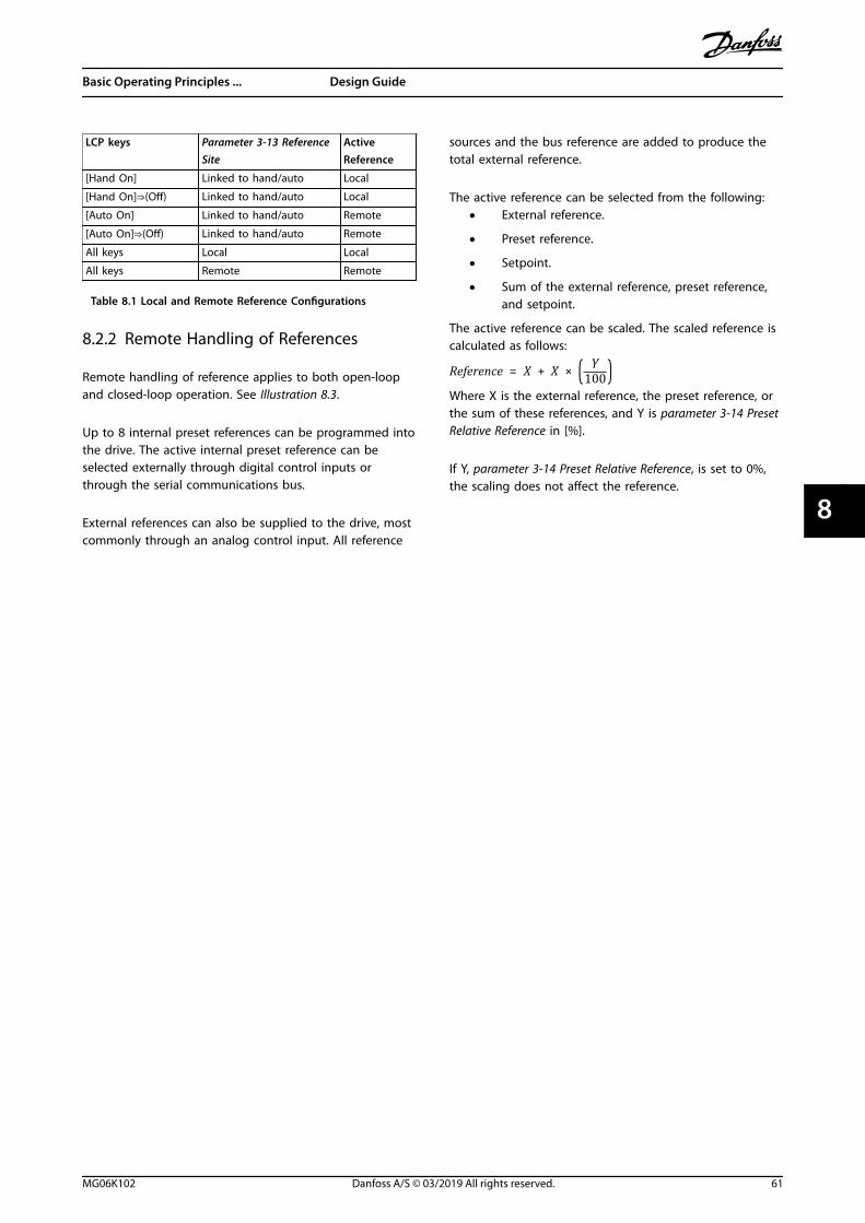
LCP keys Parameter 3-13 ReferenceSite
ActiveReference
[Hand On] Linked to hand/auto Local
[Hand On]⇒(Off) Linked to hand/auto Local
[Auto On] Linked to hand/auto Remote
[Auto On]⇒(Off) Linked to hand/auto Remote
All keys Local Local
All keys Remote Remote
Table 8.1 Local and Remote Reference Configurations
8.2.2 Remote Handling of References
Remote handling of reference applies to both open-loopand closed-loop operation. See Illustration 8.3.
Up to 8 internal preset references can be programmed intothe drive. The active internal preset reference can beselected externally through digital control inputs orthrough the serial communications bus.
External references can also be supplied to the drive, mostcommonly through an analog control input. All reference
sources and the bus reference are added to produce thetotal external reference.
The active reference can be selected from the following:• External reference.
• Preset reference.
• Setpoint.
• Sum of the external reference, preset reference,and setpoint.
The active reference can be scaled. The scaled reference iscalculated as follows:
Reference = X + X × Y100
Where X is the external reference, the preset reference, orthe sum of these references, and Y is parameter 3-14 PresetRelative Reference in [%].
If Y, parameter 3-14 Preset Relative Reference, is set to 0%,the scaling does not affect the reference.
Basic Operating Principles ... Design Guide
MG06K102 Danfoss A/S © 03/2019 All rights reserved. 61
8 8

Preset relative ref.
Pres
et re
f.Re
f. 1
sour
ce
Ext. closed loop outputs
No function
Analog inputs
Frequency inputs
No function
No function
Freeze ref.
Speed up/ speed down
ref.Remote
Ref. in %
[1]
[2]
[3]
[4]
[5]
[6]
[7]
Open loop
Freeze ref.& increase/decreaseref.
Scale toRPM,Hz or %
Scale toClosed loopunit
RelativeX+X*Y/100
DigiPot
DigiPot
DigiPot
max ref.
min ref.
[0]
on
o
Conguration mode
Closed loop
Input command:
Ref. function
Ref. PresetInput command:
Preset ref. bit0, bit1, bit2
Externalreference in %
Busreference
Open loop
From Feedback Handling
Setpoint
Conguration mode
Input command:
Input command:
Digipot ref.Increase
Decrease
Clear
DigiPot
Closed loop
Ref.
2 so
urce
Ref.
3 so
urce
Analog inputs
Frequency inputs
Analog inputs
Frequency inputs
Ext. closed loop outputs
Ext. closed loop outputs
P 3-
10P
3-15
P 3-
16P
3-17
Y
X %
%
P 1-00
P 3-14
±100%
130B
A35
7.12
P 3-04
±200%
±200% ±200%
0%
±200%
P 1-00
±200%0/1
0/1
0/1
Illustration 8.3 Remote Handling of Reference
Basic Operating Principles ... VLT® AutomationDrive FC 361
62 Danfoss A/S © 03/2019 All rights reserved. MG06K102
88
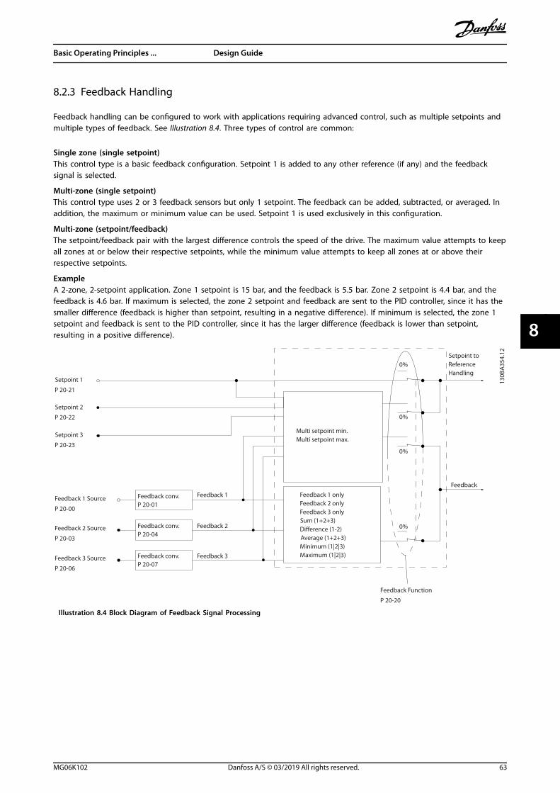
8.2.3 Feedback Handling
Feedback handling can be configured to work with applications requiring advanced control, such as multiple setpoints andmultiple types of feedback. See Illustration 8.4. Three types of control are common:
Single zone (single setpoint)This control type is a basic feedback configuration. Setpoint 1 is added to any other reference (if any) and the feedbacksignal is selected.
Multi-zone (single setpoint)This control type uses 2 or 3 feedback sensors but only 1 setpoint. The feedback can be added, subtracted, or averaged. Inaddition, the maximum or minimum value can be used. Setpoint 1 is used exclusively in this configuration.
Multi-zone (setpoint/feedback)The setpoint/feedback pair with the largest difference controls the speed of the drive. The maximum value attempts to keepall zones at or below their respective setpoints, while the minimum value attempts to keep all zones at or above theirrespective setpoints.
ExampleA 2-zone, 2-setpoint application. Zone 1 setpoint is 15 bar, and the feedback is 5.5 bar. Zone 2 setpoint is 4.4 bar, and thefeedback is 4.6 bar. If maximum is selected, the zone 2 setpoint and feedback are sent to the PID controller, since it has thesmaller difference (feedback is higher than setpoint, resulting in a negative difference). If minimum is selected, the zone 1setpoint and feedback is sent to the PID controller, since it has the larger difference (feedback is lower than setpoint,resulting in a positive difference).
Setpoint 1
P 20-21
Setpoint 2
P 20-22
Setpoint 3
P 20-23
Feedback 1 Source
P 20-00
Feedback 2 Source
P 20-03
Feedback 3 Source
P 20-06
Feedback conv.P 20-01
Feedback conv.P 20-04
Feedback conv.P 20-07
Feedback 1
Feedback 2
Feedback 3
Feedback
Feedback Function
P 20-20
Multi setpoint min.Multi setpoint max.
Feedback 1 onlyFeedback 2 onlyFeedback 3 onlySum (1+2+3)Dierence (1-2)Average (1+2+3)Minimum (1|2|3)Maximum (1|2|3)
Setpoint toReference Handling
0%
0%
0%
0%
130B
A35
4.12
Illustration 8.4 Block Diagram of Feedback Signal Processing
Basic Operating Principles ... Design Guide
MG06K102 Danfoss A/S © 03/2019 All rights reserved. 63
8 8
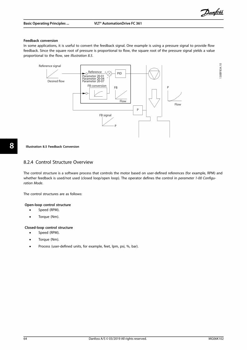
Feedback conversionIn some applications, it is useful to convert the feedback signal. One example is using a pressure signal to provide flowfeedback. Since the square root of pressure is proportional to flow, the square root of the pressure signal yields a valueproportional to the flow, see Illustration 8.5.
130B
F834
.10
Reference signal
Reference
FB conversion
FB signal
P
Flow
FB
P
Flow
PID
P
Parameter 20-01Parameter 20-04Parameter 20-07
Illustration 8.5 Feedback Conversion
8.2.4 Control Structure Overview
The control structure is a software process that controls the motor based on user-defined references (for example, RPM) andwhether feedback is used/not used (closed loop/open loop). The operator defines the control in parameter 1-00 Configu-ration Mode.
The control structures are as follows:
Open-loop control structure• Speed (RPM).
• Torque (Nm).
Closed-loop control structure• Speed (RPM).
• Torque (Nm).
• Process (user-defined units, for example, feet, lpm, psi, %, bar).
Basic Operating Principles ... VLT® AutomationDrive FC 361
64 Danfoss A/S © 03/2019 All rights reserved. MG06K102
88

8.2.5 Open-loop Control Structure
In open-loop mode, the drive uses 1 or more references (local or remote) to control the speed or torque of the motor. Thereare 2 types of open-loop control:
• Speed control. No feedback from the motor.
• Torque control. Used in VVC+ mode. The function is used in mechanically robust applications, but its accuracy islimited. Open-loop torque function works only in 1 speed direction. The torque is calculated based on currentmeasurement within the drive. See chapter 9 Application Examples.
In the configuration shown in Illustration 8.6, the drive operates in open-loop mode. It receives input from either the LCP(hand-on mode) or via a remote signal (auto-on mode).
The signal (speed reference) is received and conditioned with the following:• Programmed minimum and maximum motor speed limits (in RPM and Hz).
• Ramp-up and ramp-down times.
• Motor rotation direction.
The reference is then passed on to control the motor.
130B
B153
.10
100%
0%
-100%
100%
P 3-13Referencesite
Localreferencescaled toRPM or Hz
Auto mode
Hand mode
LCP Hand on,o and autoon keys
Linked to hand/auto
Local
Remote
ReferenceRamp
P 4-10Motor speeddirection
To motorcontrol
ReferencehandlingRemotereference
P 4-13Motor speedhigh limit [RPM]
P 4-14Motor speedhigh limit [Hz]
P 4-11Motor speedlow limit [RPM]
P 4-12Motor speedlow limit [Hz]
P 3-4* Ramp 1P 3-5* Ramp 2
Illustration 8.6 Block Diagram of an Open-loop Control Structure
Basic Operating Principles ... Design Guide
MG06K102 Danfoss A/S © 03/2019 All rights reserved. 65
8 8

8.2.6 Closed-loop Control Structure
In closed-loop mode, the drive uses 1 or more references (local or remote) and feedback sensors to control the motor. Thedrive receives a feedback signal from a sensor in the system. It then compares this feedback to a setpoint reference valueand determines if there is any discrepancy between these 2 signals. The drive then adjusts the speed of the motor tocorrect the discrepancy.
For example, consider a pump application in which the speed of the pump is controlled so that the static pressure in a pipeis constant (see Illustration 8.7). The drive receives a feedback signal from a sensor in the system. It compares this feedbackto a setpoint reference value and determines the discrepancy if any, between these 2 signals. It then adjusts the speed ofthe motor to compensate for the discrepancy.
The static pressure setpoint is the reference signal to the drive. A static pressure sensor measures the actual static pressurein the pipe and provides this information to the drive as a feedback signal. If the feedback signal exceeds the setpointreference, the drive ramps down to reduce the pressure. Similarly, if the pipe pressure is lower than the setpoint reference,the drive ramps up to increase the pump pressure.
There are 3 types of closed-loop control:• Speed control. This type of control requires a speed PID feedback for an input. A properly optimized speed closed-
loop control has higher accuracy than a speed open-loop control.
• Process control. Used to control application parameters that are measured by different sensors (pressure,temperature, and flow) and are affected by the connected motor through a pump or fan.
P 20-81PID Normal/Inverse
Control
PID
Ref.Handling
FeedbackHandling
Scale tospeed
P 4-10Motor speed
direction
To motorcontrol
(Illustra-tion)
(Illustra-tion)
130B
A35
9.12
100%
0%
-100%
100%*[-1]
_
+
Illustration 8.7 Block Diagram of Closed-loop Controller
Programmable featuresWhile the default values for the drive in closed loop often provide satisfactory performance, system control can often beoptimized by tuning the PID parameters. Auto tuning is provided for this optimization.
• Inverse regulation - motor speed increases when a feedback signal is high.
• Start-up frequency - lets the system quickly reach an operating status before the PID controller takes over.
• Built-in lowpass filter - reduces feedback signal noise.
Basic Operating Principles ... VLT® AutomationDrive FC 361
66 Danfoss A/S © 03/2019 All rights reserved. MG06K102
88

8.2.7 Control Processing
See Active/Inactive Parameters in Different Drive Control Modes in the programming guide for an overview of which controlconfiguration is available for your application, depending on selection of AC motor or PM motor.
8.2.7.1 Control Structure in VVC+
+
_
+
_
Cong. mode
Ref.
Process
P 1-00
High
+f max.
Low
-f max.
P 4-11 Motor speedlow limit (RPM)P 4-12 Motor speedlow limit (Hz)
P 4-13 Motor speedhigh limit (RPM)
P 4-14 Motor speedhigh limit (Hz)
Motorcontroller
Ramp
SpeedPID
P 7-20 Process feedback1 sourceP 7-22 Process feedback2 source
P 7-00 Speed PID
feedback source
P 1-00Cong. mode
P 4-19Max. output freq.
-f max.
Motor controller
P 4-19Max. output freq.
+f max.
P 3-**
P 7-0*
13
0B
A0
55
.10
Illustration 8.8 Control Structure in VVC+ Open-loop and Closed-loop Configurations
In Illustration 8.8, the resulting reference from the reference handling system is received and fed through the ramp limitationand speed limitation before being sent to the motor control. The output of the motor control is then limited by themaximum frequency limit.
Parameter 1-01 Motor Control Principle is set to [1] VVC+ and parameter 1-00 Configuration Mode is set to [0] Speed open loop.If parameter 1-00 Configuration Mode is set to [1] Speed closed loop, the resulting reference is passed from the ramplimitation and speed limitation into a speed PID control. The speed PID control parameters are located in parameter group7-0* Speed PID Ctrl. The resulting reference from the speed PID control is sent to the motor control limited by the frequencylimit.
Select [3] Process in parameter 1-00 Configuration Mode to use the process PID control for closed-loop control of, for example,speed or pressure in the controlled application. The process PID parameters are in parameter groups 7-2* Process Ctrl. Feedband 7-3* Process PID Ctrl.
8.2.7.2 Internal Current Control in VVC+ Mode
When the motor torque exceeds the torque limits set in parameter 4-16 Torque Limit Motor Mode, parameter 4-17 Torque LimitGenerator Mode, and parameter 4-18 Current Limit, the integral current limit control is activated.When the drive is at the current limit during motor operation or regenerative operation, it tries to get below the presettorque limits as quickly as possible without losing control of the motor.
Basic Operating Principles ... Design Guide
MG06K102 Danfoss A/S © 03/2019 All rights reserved. 67
8 8

9 Application Examples
The examples in this section are intended as a quickreference for common applications.
• Parameters associated with the terminals andtheir settings are shown next to the drawings.
• Switch settings for analog terminals A53 or A54are shown where required.
9.1 Programming a Closed-loop DriveSystem
A closed-loop drive system usually consists of thefollowing:
• Motor.
• Drive.
• Encoder as feedback system.
• Transmission.
• Gearbox.
• Load.
e30b
h107
.10
Encoder
Motor Gearbox
Load
Transmission
Illustration 9.1 Basic Set-up for Closed-loop Speed Control
9.2 Wiring for Open-loop Speed Control
Parameters
+10 V
A IN
A IN
COM
A OUT
COM
50
53
54
55
42
39
A53
U - I
0 – 10 V
+
-
e30b
b92
6.11FC
Function Setting
Parameter 6-10 Terminal 53 Low Voltage
0.07 V*
Parameter 6-11 Terminal 53 High Voltage
10 V*
Parameter 6-14 Terminal 53 Low Ref./Feedb. Value
0 Hz
Parameter 6-15 Terminal 53 High Ref./Feedb. Value
50 Hz
* = Default value
Notes/comments:Assumptions are 0 V DC input= 0 Hz speed and 10 V DCinput = 50 Hz speed.
Table 9.1 Analog Speed Reference (Voltage)
Parameters
+10 V
A IN
A IN
COM
A OUT
COM
50
53
54
55
42
39
+
-
FC
e30b
b92
7.11
A53
U - I
4 - 20mA
Function Setting
Parameter 6-12 Terminal53 Low Current
4 mA*
Parameter 6-13 Terminal53 High Current
20 mA*
Parameter 6-14 Terminal53 Low Ref./Feedb.Value
0 Hz
Parameter 6-15 Terminal53 High Ref./Feedb.Value
50 Hz
* = Default value
Notes/comments:Assumptions are 4 mA input =0 Hz speed and 20 mA input =50 Hz speed.
Table 9.2 Analog Speed Reference (Current)
Application Examples VLT® AutomationDrive FC 361
68 Danfoss A/S © 03/2019 All rights reserved. MG06K102
99

Parameters
+10 V
A IN
A IN
COM
A OUT
COM
50
53
54
55
42
39
A53
U - I
≈ 5kΩ
e30b
b68
3.11FC
Function Setting
Parameter 6-12 Terminal53 Low Current
4 mA*
Parameter 6-13 Terminal53 High Current
20 mA*
Parameter 6-14 Terminal53 Low Ref./Feedb.Value
0 Hz
Parameter 6-15 Terminal53 High Ref./Feedb.Value
50 Hz
* = Default value
Notes/comments:Assumptions are 0 V DC input= 0 RPM speed and 10 V DCinput = 1500 RPM speed.
Table 9.3 Speed Reference (Using a Manual Potentiometer)
Parameters
FC
+24 V
+24 V
D IN
D IN
D IN
COM
D IN
D IN
D IN
12
13
18
19
20
27
29
32
33
e30b
g503
.10 Function Setting
Parameter 5-10 Terminal 18 Digital Input
[8] Start*
Parameter 5-12 Terminal 27 Digital Input
[19]Freeze
Reference
Parameter 5-13 Terminal 29 Digital Input
[21]Speed Up
Parameter 5-14 Terminal 32 Digital Input
[22]SpeedDown
* = Default value
Notes/comments:
Table 9.4 Speed Up/Speed Down
130B
B840
.12Speed
Reference
Start (18)
Freeze ref (27)
Speed up (29)
Speed down (32)
Illustration 9.2 Speed Up/Speed Down
9.3 Wiring for Start/Stop
Parameters
FC
+24 V
+24 V
D IN
D IN
D IN
COM
D IN
D IN
D IN
12
13
18
19
20
27
29
32
33
e30b
g504
.10 Function Setting
Parameter 5-10 Terminal 18Digital Input
[8] Start*
Parameter 5-12 Terminal 27Digital Input
[0] Nooperation
* = Default value
Notes/comments:If parameter 5-12 Terminal 27Digital Input is set to [0] Nooperation, a jumper wire toterminal 27 is not needed.
Table 9.5 Start/Stop Command
130B
B805
.12
Speed
Start/Stop (18)
Illustration 9.3 Start/Stop Command
Parameters
FC
+24 V
+24 V
D IN
D IN
D IN
COM
D IN
D IN
D IN
+10 V
A IN
A IN
COM
A OUT
COM
12
13
18
19
20
27
29
32
33
50
53
54
55
42
39
e30b
g505
.10 Function Setting
Parameter 5-10 Terminal 18Digital Input
[9] LatchedStart
Parameter 5-12 Terminal 27Digital Input
[6] Stop Inverse
* = Default value
Notes/comments:
Table 9.6 Pulse Start/Stop
Application Examples Design Guide
MG06K102 Danfoss A/S © 03/2019 All rights reserved. 69
9 9

Speed
130B
B806
.10
Latched Start (18)
Stop Inverse (27)
Illustration 9.4 Latched Start/Stop Inverse
Parameters
FC
+24 V
+24 V
D IN
D IN
D IN
COM
D IN
D IN
D IN
+10 VA IN
A IN
COM
A OUT
COM
12
13
18
19
20
27
29
32
33
50
53
54
55
42
39
130B
B934
.11
Function Setting
Parameter 5-10 Terminal 18Digital Input
[8] Start
Parameter 5-11 Terminal 19Digital Input
[10]Reversing*
Parameter 5-12 Terminal 27Digital Input
[0] Nooperation
Parameter 5-14 Terminal 32Digital Input
[16] Preset refbit 0
Parameter 5-15 Terminal 33Digital Input
[17] Preset refbit 1
Parameter 3-10 PresetReference
Preset ref. 0Preset ref. 1Preset ref. 2Preset ref. 3
25%50%75%
100%
* = Default value
Notes/comments:
Table 9.7 Start/Stop with Reversing and 4 Preset Speeds
9.4 Wiring for External Alarm Reset
Parameters
FC
+24 V
+24 V
D IN
D IN
D IN
COM
D IN
D IN
D IN
+10 V
A IN
A IN
COM
A OUT
COM
12
13
18
19
20
27
29
32
33
50
53
54
55
42
39
e30b
g506
.10 Function Setting
Parameter 5-11 Terminal 19Digital Input
[1] Reset
* = Default value
Notes/comments:
Table 9.8 External Alarm Reset
Application Examples VLT® AutomationDrive FC 361
70 Danfoss A/S © 03/2019 All rights reserved. MG06K102
99
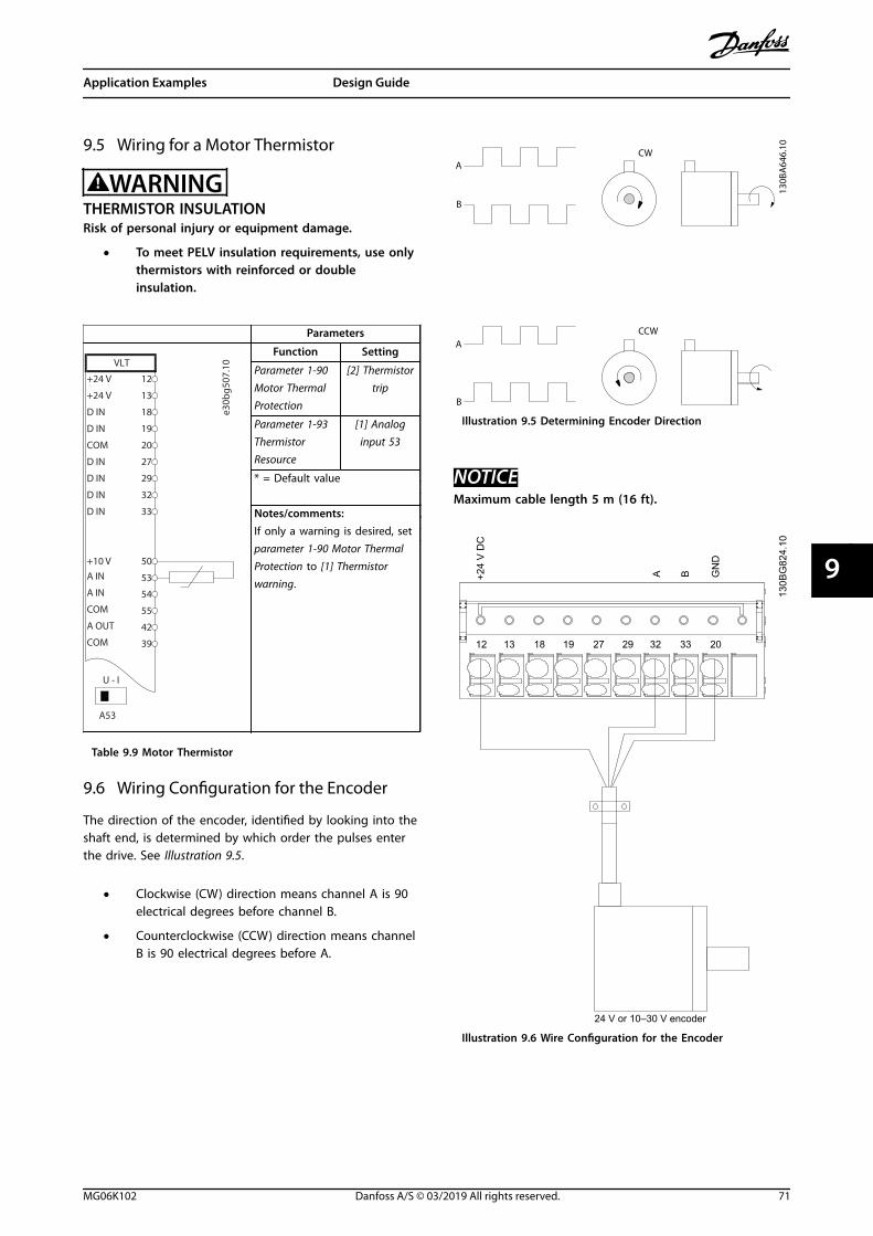
9.5 Wiring for a Motor Thermistor
WARNINGTHERMISTOR INSULATIONRisk of personal injury or equipment damage.
• To meet PELV insulation requirements, use onlythermistors with reinforced or doubleinsulation.
Parameters
e30b
g507
.10VLT
+24 V
+24 V
D IN
D IN
D IN
COM
D IN
D IN
D IN
+10 V
A IN
A IN
COM
A OUT
COM
12
13
18
19
20
27
29
32
33
50
53
54
55
42
39
A53
U - I
Function Setting
Parameter 1-90 Motor ThermalProtection
[2] Thermistortrip
Parameter 1-93 ThermistorResource
[1] Analoginput 53
* = Default value
Notes/comments:If only a warning is desired, setparameter 1-90 Motor ThermalProtection to [1] Thermistorwarning.
Table 9.9 Motor Thermistor
9.6 Wiring Configuration for the Encoder
The direction of the encoder, identified by looking into theshaft end, is determined by which order the pulses enterthe drive. See Illustration 9.5.
• Clockwise (CW) direction means channel A is 90electrical degrees before channel B.
• Counterclockwise (CCW) direction means channelB is 90 electrical degrees before A.
B
A
B
A
130B
A64
6.10
CW
CCW
Illustration 9.5 Determining Encoder Direction
NOTICEMaximum cable length 5 m (16 ft).
130B
G82
4.10
+24
V D
C
A B GN
D
1312 18 322719 29 33 20
24 V or 10–30 V encoder
Illustration 9.6 Wire Configuration for the Encoder
Application Examples Design Guide
MG06K102 Danfoss A/S © 03/2019 All rights reserved. 71
9 9

10 How to Order a Drive
10.1 Drive Configurator
F C - T
e30b
h108
.11
X S A BX X X X
1 2 3 4 5 6 7 8 9 10 11 12 13 14 15 16 17 18 19 20 302221 23 272524 26 28 29 31 32
X3 6 1 4 E 2 0 H 2 X X C X X
Table 10.1 Type Code String
Product group 1–6 Model 7–10 Mains Voltage 11–12 Enclosure 13–15 Hardware configuration 16–23 RFI filter 16–17 Brake 18 Display (LCP) 19 PCB coating 20 Mains option 21 Adaptation A 22 Adaptation B 23 Software release 24–27 Software language 28 A options 29–30 B options 31–32
Table 10.2 Type Code Example for Ordering a Drive
Configure the correct drive for the proper application byusing the internet-based drive configurator. The driveconfigurator is found on the global internet site:www.danfoss.com/drives. The configurator creates a typecode string and an 8-digit sales number, which can bedelivered to the local sales office. It is also possible tobuild a project list with several products and send it to aDanfoss sales representative.
An example of a type code string is:
FC-361N132T4E20H2XXCXXXSXXXXA0BX
The meaning of the characters in the string is defined inthis chapter. In the example above, a drive is configuredwith the following options:
• RFI filter, Class A2.
• 3C3.
• PROFIBUS DP-V1.
Drives are delivered automatically with English andChinese languages.
How to Order a Drive VLT® AutomationDrive FC 361
72 Danfoss A/S © 03/2019 All rights reserved. MG06K102
1010

10.1.1 Ordering Type Code for Enclosures J8–J9
Description Pos Possible choice
Product group 1-6 FC-361
Model 7–10 N90: 90 kW (125 hp)N110: 110 kW (150 hp)N132: 132 kW (200 hp)N160: 160 kW (250 hp)N200: 200 kW (300 hp)N250: 250 kW (350 hp)N315: 315 kW (450 hp)
Mains voltage 11-12 T4: 380–480 V AC
Enclosure 13-15 E20: IP20
RFI filter 16-17 H2: RFI filter, class A2
Brake 18 X: No brake IGBT
Display 19 X: No Local Control Panel
PCB coating 20 C: 3C3
Mains option 21 X: No mains option
Adaptation 22 X: Standard cable entries
Adaptation 23 X: No adaptation
Software release 24-27 SXXX: Standard software
Software language 28 X: Standard language pack
Table 10.3 Ordering Type Code for Enclosures J8–J9
1) Available for all D-frames.
10.1.2 Ordering Options for All VLT® AutomationDrive FC 361 Enclosures
Description Pos Possible option
A options 29–30 AX: No A option
A0: VLT® PROFIBUS DP MCA 101
AL: VLT® PROFINET MCA 120
B options 31–32 BX: No option
Table 10.4 Ordering Type Codes for FC 361 Options
How to Order a Drive Design Guide
MG06K102 Danfoss A/S © 03/2019 All rights reserved. 73
10 10

10.2 Ordering Numbers for Options and Accessories
10.2.1 Ordering Numbers for B Options: Functional Extensions
Description Ordering number
VLT® General Purpose I/O MCB 101 134B6786
VLT® Encoder Input MCB 102 132b0282
VLT® Resolver Input MCB 103 132b0283
Table 10.5 Ordering Numbers for B Options
10.2.2 Ordering Numbers for J8–J9 Kits
Type Description Ordering number
LCP
LCP 101 Numerical local control panel (NLCP). 130B1124
LCP 102 Graphical local control panel (GLCP). 130B1107
LCP cable Separate LCP cable, 3 m (9 ft). 175Z0929
LCP kit, IP21 Panel mounting kit including graphical LCP, fasteners, 3 m (9 ft) cableand gasket.
130B1113
LCP kit, IP21 Panel mounting kit including numerical LCP, fasteners and gasket. 130B1114
LCP kit, IP21 Panel mounting kit for all LCPs including fasteners, 3 m (9 ft) cableand gasket.
130B1117
Table 10.6 Kits Available for Enclosures J8–J9
10.3 Spare Parts
Consult the VLT® Shop or the Drive Configurator (www.danfoss.com/drives) for the spare parts that are available for yourapplication.
How to Order a Drive VLT® AutomationDrive FC 361
74 Danfoss A/S © 03/2019 All rights reserved. MG06K102
1010
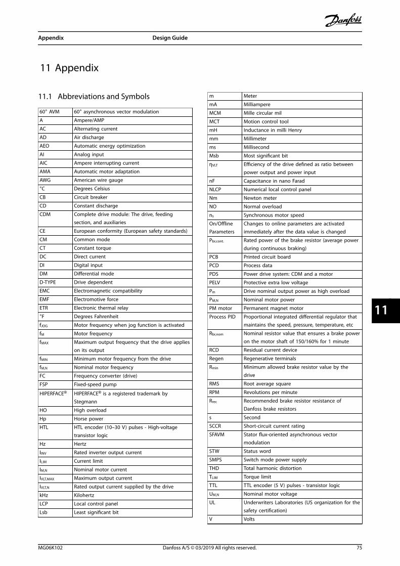
11 Appendix
11.1 Abbreviations and Symbols
60° AVM 60° asynchronous vector modulation
A Ampere/AMP
AC Alternating current
AD Air discharge
AEO Automatic energy optimization
AI Analog input
AIC Ampere interrupting current
AMA Automatic motor adaptation
AWG American wire gauge
°C Degrees Celsius
CB Circuit breaker
CD Constant discharge
CDM Complete drive module: The drive, feedingsection, and auxiliaries
CE European conformity (European safety standards)
CM Common mode
CT Constant torque
DC Direct current
DI Digital input
DM Differential mode
D-TYPE Drive dependent
EMC Electromagnetic compatibility
EMF Electromotive force
ETR Electronic thermal relay
°F Degrees Fahrenheit
fJOG Motor frequency when jog function is activated
fM Motor frequency
fMAX Maximum output frequency that the drive applieson its output
fMIN Minimum motor frequency from the drive
fM,N Nominal motor frequency
FC Frequency converter (drive)
FSP Fixed-speed pump
HIPERFACE® HIPERFACE® is a registered trademark byStegmann
HO High overload
Hp Horse power
HTL HTL encoder (10–30 V) pulses - High-voltagetransistor logic
Hz Hertz
IINV Rated inverter output current
ILIM Current limit
IM,N Nominal motor current
IVLT,MAX Maximum output current
IVLT,N Rated output current supplied by the drive
kHz Kilohertz
LCP Local control panel
Lsb Least significant bit
m Meter
mA Milliampere
MCM Mille circular mil
MCT Motion control tool
mH Inductance in milli Henry
mm Millimeter
ms Millisecond
Msb Most significant bit
ηVLT Efficiency of the drive defined as ratio betweenpower output and power input
nF Capacitance in nano Farad
NLCP Numerical local control panel
Nm Newton meter
NO Normal overload
ns Synchronous motor speed
On/OfflineParameters
Changes to online parameters are activatedimmediately after the data value is changed
Pbr,cont. Rated power of the brake resistor (average powerduring continuous braking)
PCB Printed circuit board
PCD Process data
PDS Power drive system: CDM and a motor
PELV Protective extra low voltage
Pm Drive nominal output power as high overload
PM,N Nominal motor power
PM motor Permanent magnet motor
Process PID Proportional integrated differential regulator thatmaintains the speed, pressure, temperature, etc
Rbr,nom Nominal resistor value that ensures a brake poweron the motor shaft of 150/160% for 1 minute
RCD Residual current device
Regen Regenerative terminals
Rmin Minimum allowed brake resistor value by thedrive
RMS Root average square
RPM Revolutions per minute
Rrec Recommended brake resistor resistance ofDanfoss brake resistors
s Second
SCCR Short-circuit current rating
SFAVM Stator flux-oriented asynchronous vectormodulation
STW Status word
SMPS Switch mode power supply
THD Total harmonic distortion
TLIM Torque limit
TTL TTL encoder (5 V) pulses - transistor logic
UM,N Nominal motor voltage
UL Underwriters Laboratories (US organization for thesafety certification)
V Volts
Appendix Design Guide
MG06K102 Danfoss A/S © 03/2019 All rights reserved. 75
11 11
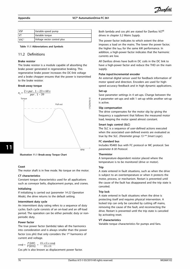
VSP Variable-speed pump
VT Variable torque
VVC+ Voltage vector control plus
Table 11.1 Abbreviations and Symbols
11.2 Definitions
Brake resistorThe brake resistor is a module capable of absorbing thebrake power generated in regenerative braking. Thisregenerative brake power increases the DC-link voltageand a brake chopper ensures that the power is transmittedto the brake resistor.
Break-away torque
ns = 2 × par . 1 − 23 × 60 spar . 1 − 39
175Z
A07
8.10
Pull-out
RPM
Torque
Illustration 11.1 Break-away Torque Chart
CoastThe motor shaft is in free mode. No torque on the motor.
CT characteristicsConstant torque characteristics used for all applicationssuch as conveyor belts, displacement pumps, and cranes.
InitializingIf initializing is carried out (parameter 14-22 OperationMode), the drive returns to the default setting.
Intermittent duty cycleAn intermittent duty rating refers to a sequence of dutycycles. Each cycle consists of an on-load and an off-loadperiod. The operation can be either periodic duty or non-periodic duty.
Power factorThe true power factor (lambda) takes all the harmonicsinto consideration and is always smaller than the powerfactor (cos phi) that only considers the 1st harmonics ofcurrent and voltage.
cosϕ = P kWP kVA = Uλ x Iλ x cosϕUλ x IλCos phi is also known as displacement power factor.
Both lambda and cos phi are stated for Danfoss VLT®
drives in chapter 5.2 Mains Supply.
The power factor indicates to which extent the driveimposes a load on the mains. The lower the power factor,the higher the IRMS for the same kW performance. Inaddition, a high-power factor indicates that the harmoniccurrents are low.
All Danfoss drives have built-in DC coils in the DC link tohave a high-power factor and reduce the THD on the mainsupply.
Pulse input/incremental encoderAn external digital sensor used for feedback information ofmotor speed and direction. Encoders are used for high-speed accuracy feedback and in high dynamic applications.
Set-upSave parameter settings in 4 set-ups. Change between the4 parameter set-ups and edit 1 set-up while another set-upis active.
Slip compensationThe drive compensates for the motor slip by giving thefrequency a supplement that follows the measured motorload, keeping the motor speed almost constant.
Smart logic control (SLC)The SLC is a sequence of user-defined actions executedwhen the associated user-defined events are evaluated astrue by the SLC. (Parameter group 13-** Smart Logic).
FC standard busIncludes RS485 bus with FC protocol or MC protocol. Seeparameter 8-30 Protocol.
ThermistorA temperature-dependent resistor placed where thetemperature is to be monitored (drive or motor).
TripA state entered in fault situations, such as when the driveis subject to an overtemperature or when it protects themotor, process, or mechanism. Restart is prevented untilthe cause of the fault has disappeared and the trip state iscanceled.
Trip lockA state entered in fault situations when the drive isprotecting itself and requires physical intervention. Alocked trip can only be canceled by cutting off mains,removing the cause of the fault, and reconnecting thedrive. Restart is prevented until the trip state is canceledby activating reset.
VT characteristicsVariable torque characteristics for pumps and fans.
Appendix VLT® AutomationDrive FC 361
76 Danfoss A/S © 03/2019 All rights reserved. MG06K102
1111
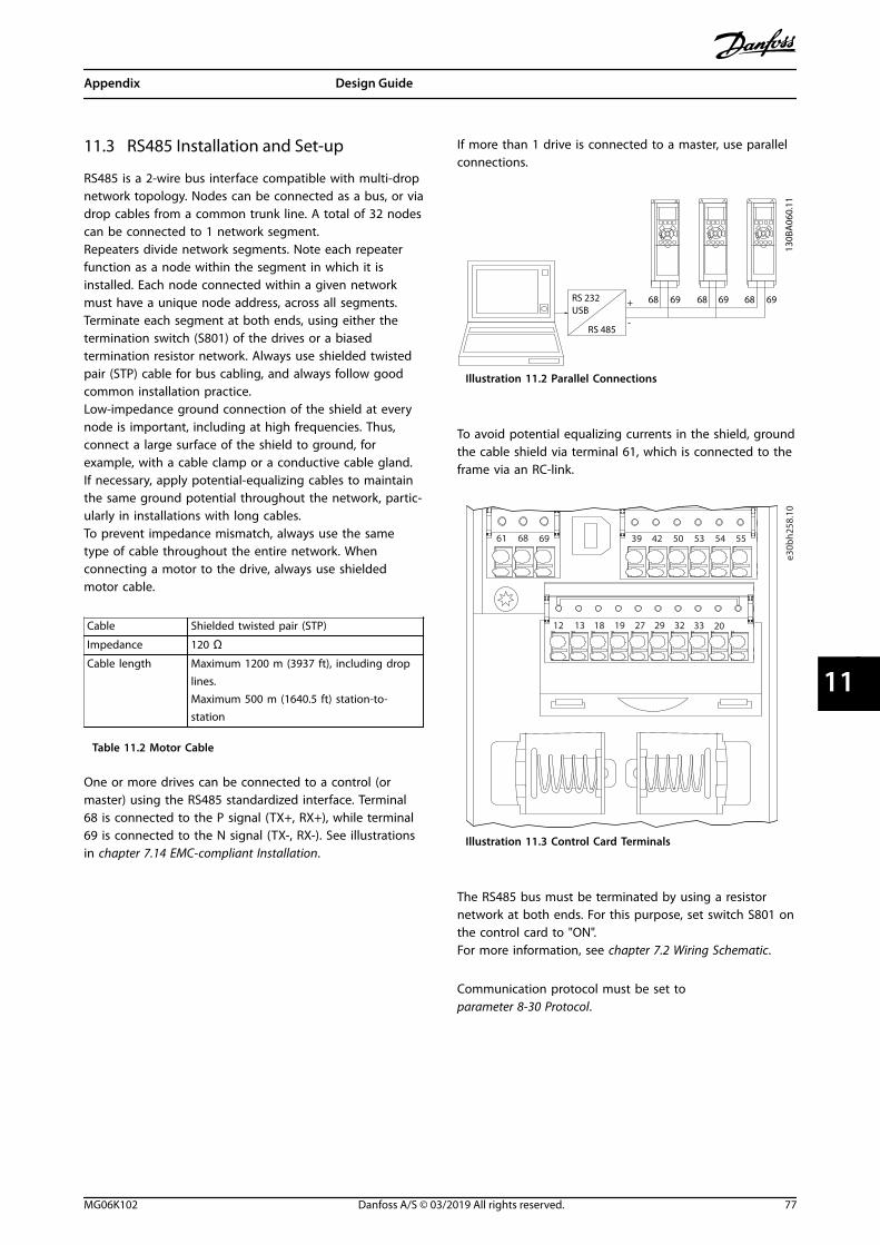
11.3 RS485 Installation and Set-up
RS485 is a 2-wire bus interface compatible with multi-dropnetwork topology. Nodes can be connected as a bus, or viadrop cables from a common trunk line. A total of 32 nodescan be connected to 1 network segment.Repeaters divide network segments. Note each repeaterfunction as a node within the segment in which it isinstalled. Each node connected within a given networkmust have a unique node address, across all segments.Terminate each segment at both ends, using either thetermination switch (S801) of the drives or a biasedtermination resistor network. Always use shielded twistedpair (STP) cable for bus cabling, and always follow goodcommon installation practice.Low-impedance ground connection of the shield at everynode is important, including at high frequencies. Thus,connect a large surface of the shield to ground, forexample, with a cable clamp or a conductive cable gland.If necessary, apply potential-equalizing cables to maintainthe same ground potential throughout the network, partic-ularly in installations with long cables.To prevent impedance mismatch, always use the sametype of cable throughout the entire network. Whenconnecting a motor to the drive, always use shieldedmotor cable.
Cable Shielded twisted pair (STP)
Impedance 120 ΩCable length Maximum 1200 m (3937 ft), including drop
lines.Maximum 500 m (1640.5 ft) station-to-station
Table 11.2 Motor Cable
One or more drives can be connected to a control (ormaster) using the RS485 standardized interface. Terminal68 is connected to the P signal (TX+, RX+), while terminal69 is connected to the N signal (TX-, RX-). See illustrationsin chapter 7.14 EMC-compliant Installation.
If more than 1 drive is connected to a master, use parallelconnections.
130B
A06
0.11
68 69 68 69 68 69
RS 485
RS 232USB
+
-
Illustration 11.2 Parallel Connections
To avoid potential equalizing currents in the shield, groundthe cable shield via terminal 61, which is connected to theframe via an RC-link.
e30b
h258
.10
12 13 18 19 27 29 32 33 20
61 68 69 39 42 50 53 54 55
Illustration 11.3 Control Card Terminals
The RS485 bus must be terminated by using a resistornetwork at both ends. For this purpose, set switch S801 onthe control card to "ON".For more information, see chapter 7.2 Wiring Schematic.
Communication protocol must be set toparameter 8-30 Protocol.
Appendix Design Guide
MG06K102 Danfoss A/S © 03/2019 All rights reserved. 77
11 11

11.3.1 EMC Precautions
To achieve interference-free operation of the RS485network, the following EMC precautions are recommended.
Relevant national and local regulations regardingprotective ground connection, for example, must beobserved. The RS485 communication cable must be keptaway from motor and brake resistor cables to avoidcoupling of high-frequency noise from 1 cable to another.Normally a distance of 200 mm (8 in) is sufficient. However,in situations where cables run in parallel over longdistances, keeping the greatest possible distance betweencables is recommended. When crossing is unavoidable, theRS485 cable must cross motor and brake resistor cables atan angle of 90°.
(2000 mm (78.7 in))Minimum
90° crossing
e30b
a080
.12
Fieldbus cable
Illustration 11.4 EMC Precautions
11.4 RS485: FC Protocol Overview
11.4.1 FC Protocol Overview
The FC protocol, also referred to as FC bus or standard bus,is the Danfoss standard fieldbus. It defines an accesstechnique according to the master/slave principle forcommunications via a field bus.One master and a maximum of 126 slaves can beconnected to the bus. The master selects the individualslaves via an address character in the telegram. The slaveitself can never transmit without first being requested todo so, and direct message transfer between the individualslaves is not possible. Communications occur in the half-duplex mode.The master function cannot be transferred to another node(single-master system).
The physical layer is RS485, thus utilizing the RS485 portbuilt into the drive. The FC protocol supports differenttelegram formats:
• A short format of 8 bytes for process data.
• A long format of 16 bytes that also includes aparameter channel.
• A format used for texts.
11.4.2 Drive Set-up
Set the following parameters to enable the FC protocol forthe drive.
Parameter number Setting
Parameter 8-30 Protocol FC
Parameter 8-31 Address 1–126
Parameter 8-32 FC PortBaud Rate
2400–115200
Parameter 8-33 Parity /Stop Bits
Even parity, 1 stop bit (default)
Table 11.3 FC Protocol Parameters
Appendix VLT® AutomationDrive FC 361
78 Danfoss A/S © 03/2019 All rights reserved. MG06K102
1111
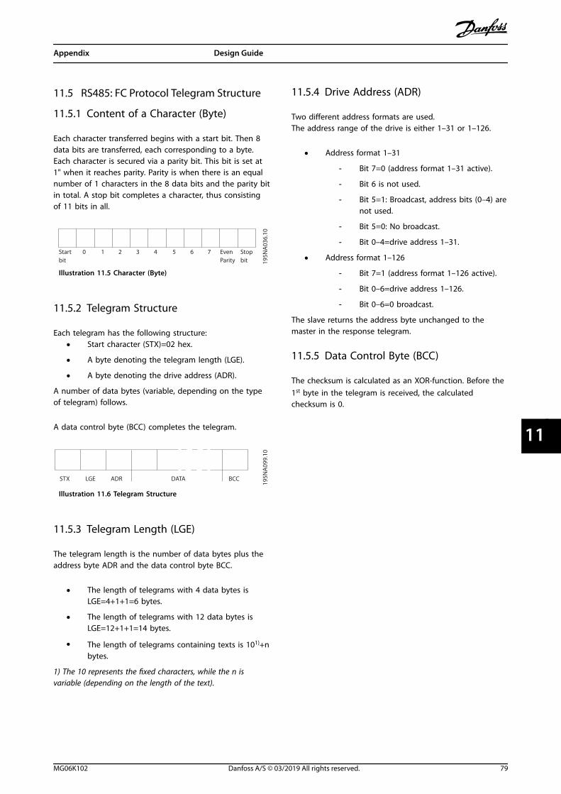
11.5 RS485: FC Protocol Telegram Structure
11.5.1 Content of a Character (Byte)
Each character transferred begins with a start bit. Then 8data bits are transferred, each corresponding to a byte.Each character is secured via a parity bit. This bit is set at1" when it reaches parity. Parity is when there is an equalnumber of 1 characters in the 8 data bits and the parity bitin total. A stop bit completes a character, thus consistingof 11 bits in all.
0 1 32 4 5 6 7
195N
A03
6.10
Startbit
Even StopParity bit
Illustration 11.5 Character (Byte)
11.5.2 Telegram Structure
Each telegram has the following structure:• Start character (STX)=02 hex.
• A byte denoting the telegram length (LGE).
• A byte denoting the drive address (ADR).
A number of data bytes (variable, depending on the typeof telegram) follows.
A data control byte (BCC) completes the telegram.
STX LGE ADR DATA BCC
195N
A09
9.10
Illustration 11.6 Telegram Structure
11.5.3 Telegram Length (LGE)
The telegram length is the number of data bytes plus theaddress byte ADR and the data control byte BCC.
• The length of telegrams with 4 data bytes isLGE=4+1+1=6 bytes.
• The length of telegrams with 12 data bytes isLGE=12+1+1=14 bytes.
• The length of telegrams containing texts is 101)+nbytes.
1) The 10 represents the fixed characters, while the n isvariable (depending on the length of the text).
11.5.4 Drive Address (ADR)
Two different address formats are used.The address range of the drive is either 1–31 or 1–126.
• Address format 1–31
- Bit 7=0 (address format 1–31 active).
- Bit 6 is not used.
- Bit 5=1: Broadcast, address bits (0–4) arenot used.
- Bit 5=0: No broadcast.
- Bit 0–4=drive address 1–31.
• Address format 1–126
- Bit 7=1 (address format 1–126 active).
- Bit 0–6=drive address 1–126.
- Bit 0–6=0 broadcast.
The slave returns the address byte unchanged to themaster in the response telegram.
11.5.5 Data Control Byte (BCC)
The checksum is calculated as an XOR-function. Before the1st byte in the telegram is received, the calculatedchecksum is 0.
Appendix Design Guide
MG06K102 Danfoss A/S © 03/2019 All rights reserved. 79
11 11
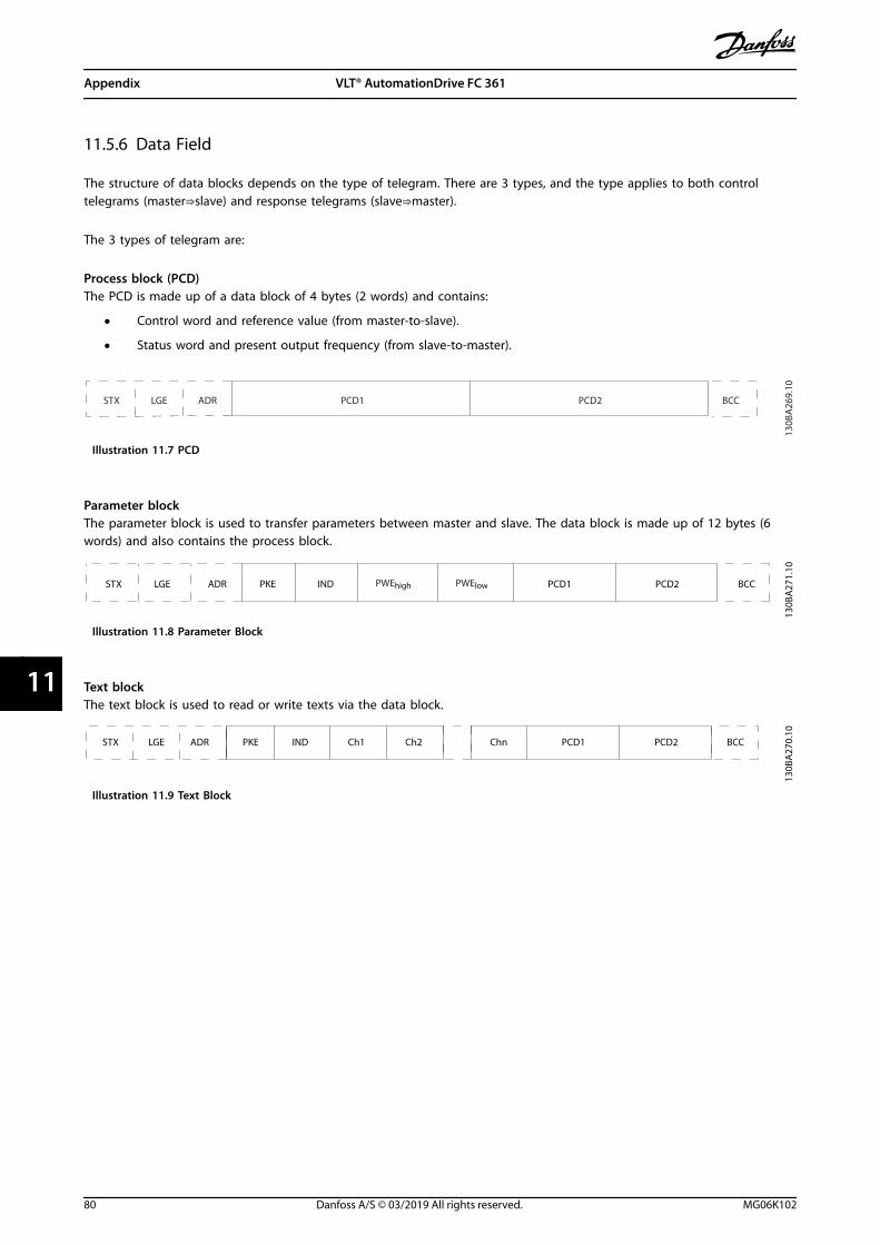
11.5.6 Data Field
The structure of data blocks depends on the type of telegram. There are 3 types, and the type applies to both controltelegrams (master⇒slave) and response telegrams (slave⇒master).
The 3 types of telegram are:
Process block (PCD)The PCD is made up of a data block of 4 bytes (2 words) and contains:
• Control word and reference value (from master-to-slave).
• Status word and present output frequency (from slave-to-master).
ADRLGESTX PCD1 PCD2 BCC
130B
A26
9.10
Illustration 11.7 PCD
Parameter blockThe parameter block is used to transfer parameters between master and slave. The data block is made up of 12 bytes (6words) and also contains the process block.
PKE INDADRLGESTX PCD1 PCD2 BCC
130B
A27
1.10
PWEhigh PWElow
Illustration 11.8 Parameter Block
Text blockThe text block is used to read or write texts via the data block.
PKE IND
130B
A27
0.10
ADRLGESTX PCD1 PCD2 BCCCh1 Ch2 Chn
Illustration 11.9 Text Block
Appendix VLT® AutomationDrive FC 361
80 Danfoss A/S © 03/2019 All rights reserved. MG06K102
1111
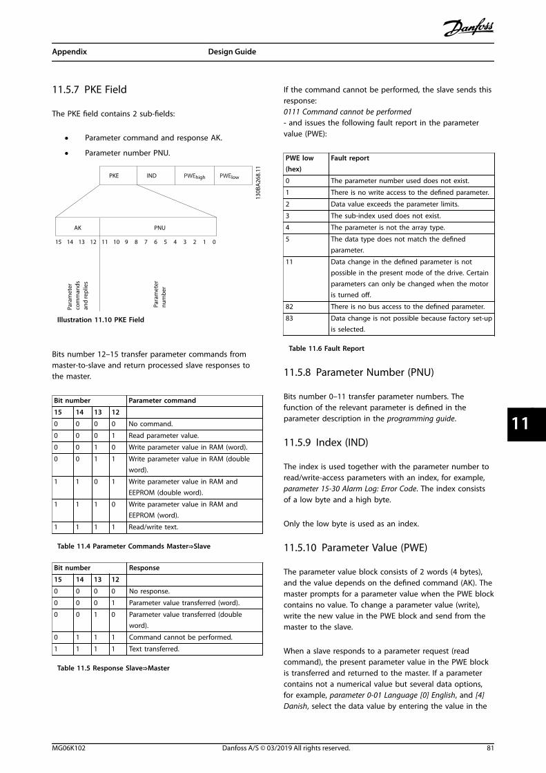
11.5.7 PKE Field
The PKE field contains 2 sub-fields:
• Parameter command and response AK.
• Parameter number PNU.
15 14 13 12 11 10 9 8 7 6 5 4 3 2 1 0
130B
A26
8.11
PKE IND PWEhigh PWElow
AK PNU
Para
met
er
com
man
ds
and
repl
ies
Para
met
ernu
mbe
r
Illustration 11.10 PKE Field
Bits number 12–15 transfer parameter commands frommaster-to-slave and return processed slave responses tothe master.
Bit number Parameter command
15 14 13 12
0 0 0 0 No command.
0 0 0 1 Read parameter value.
0 0 1 0 Write parameter value in RAM (word).
0 0 1 1 Write parameter value in RAM (doubleword).
1 1 0 1 Write parameter value in RAM andEEPROM (double word).
1 1 1 0 Write parameter value in RAM andEEPROM (word).
1 1 1 1 Read/write text.
Table 11.4 Parameter Commands Master⇒Slave
Bit number Response
15 14 13 12
0 0 0 0 No response.
0 0 0 1 Parameter value transferred (word).
0 0 1 0 Parameter value transferred (doubleword).
0 1 1 1 Command cannot be performed.
1 1 1 1 Text transferred.
Table 11.5 Response Slave⇒Master
If the command cannot be performed, the slave sends thisresponse:0111 Command cannot be performed- and issues the following fault report in the parametervalue (PWE):
PWE low(hex)
Fault report
0 The parameter number used does not exist.
1 There is no write access to the defined parameter.
2 Data value exceeds the parameter limits.
3 The sub-index used does not exist.
4 The parameter is not the array type.
5 The data type does not match the definedparameter.
11 Data change in the defined parameter is notpossible in the present mode of the drive. Certainparameters can only be changed when the motoris turned off.
82 There is no bus access to the defined parameter.
83 Data change is not possible because factory set-upis selected.
Table 11.6 Fault Report
11.5.8 Parameter Number (PNU)
Bits number 0–11 transfer parameter numbers. Thefunction of the relevant parameter is defined in theparameter description in the programming guide.
11.5.9 Index (IND)
The index is used together with the parameter number toread/write-access parameters with an index, for example,parameter 15-30 Alarm Log: Error Code. The index consistsof a low byte and a high byte.
Only the low byte is used as an index.
11.5.10 Parameter Value (PWE)
The parameter value block consists of 2 words (4 bytes),and the value depends on the defined command (AK). Themaster prompts for a parameter value when the PWE blockcontains no value. To change a parameter value (write),write the new value in the PWE block and send from themaster to the slave.
When a slave responds to a parameter request (readcommand), the present parameter value in the PWE blockis transferred and returned to the master. If a parametercontains not a numerical value but several data options,for example, parameter 0-01 Language [0] English, and [4]Danish, select the data value by entering the value in the
Appendix Design Guide
MG06K102 Danfoss A/S © 03/2019 All rights reserved. 81
11 11
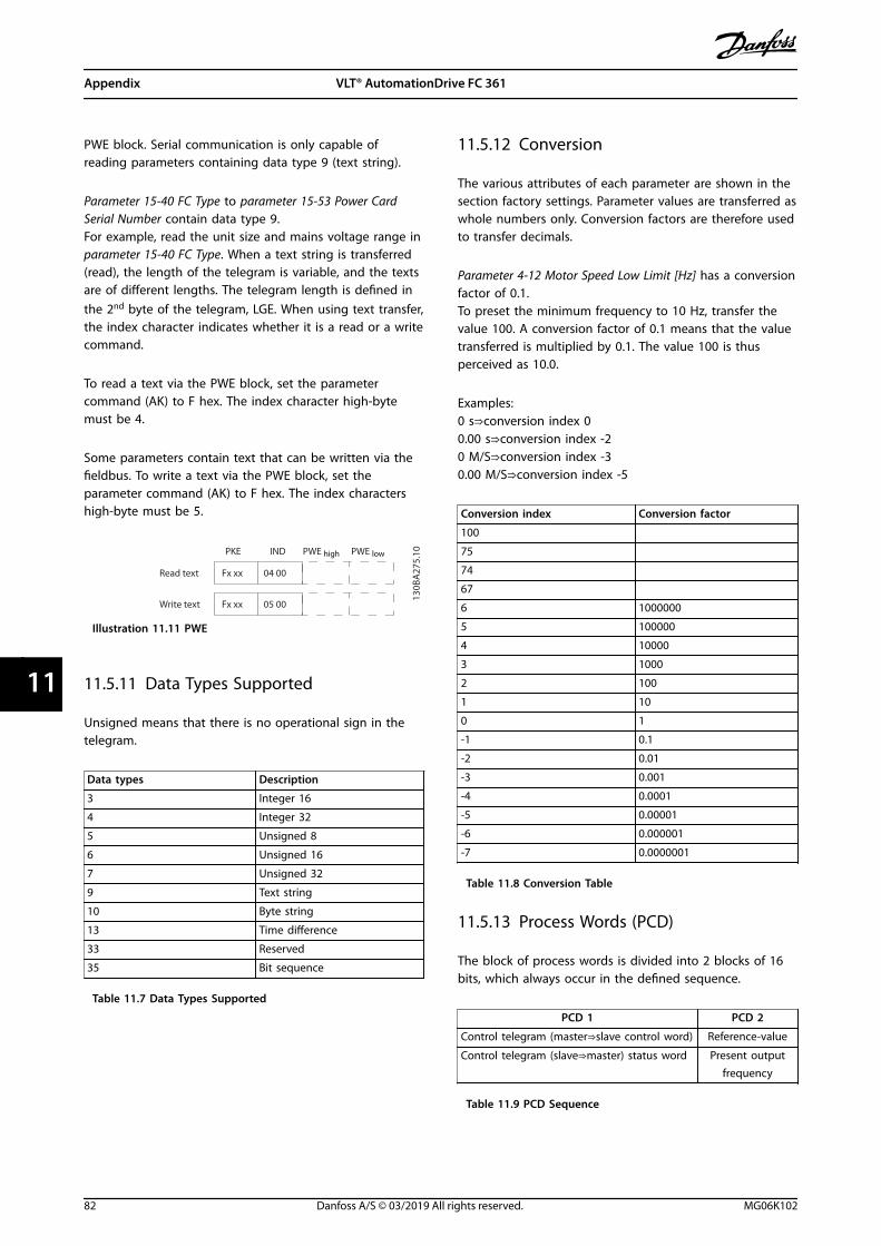
PWE block. Serial communication is only capable ofreading parameters containing data type 9 (text string).
Parameter 15-40 FC Type to parameter 15-53 Power CardSerial Number contain data type 9.For example, read the unit size and mains voltage range inparameter 15-40 FC Type. When a text string is transferred(read), the length of the telegram is variable, and the textsare of different lengths. The telegram length is defined inthe 2nd byte of the telegram, LGE. When using text transfer,the index character indicates whether it is a read or a writecommand.
To read a text via the PWE block, set the parametercommand (AK) to F hex. The index character high-bytemust be 4.
Some parameters contain text that can be written via thefieldbus. To write a text via the PWE block, set theparameter command (AK) to F hex. The index charactershigh-byte must be 5.
PWE high PWE low
Read text
Write text
130B
A27
5.10PKE IND
Fx xx 04 00
Fx xx 05 00
Illustration 11.11 PWE
11.5.11 Data Types Supported
Unsigned means that there is no operational sign in thetelegram.
Data types Description
3 Integer 16
4 Integer 32
5 Unsigned 8
6 Unsigned 16
7 Unsigned 32
9 Text string
10 Byte string
13 Time difference
33 Reserved
35 Bit sequence
Table 11.7 Data Types Supported
11.5.12 Conversion
The various attributes of each parameter are shown in thesection factory settings. Parameter values are transferred aswhole numbers only. Conversion factors are therefore usedto transfer decimals.
Parameter 4-12 Motor Speed Low Limit [Hz] has a conversionfactor of 0.1.To preset the minimum frequency to 10 Hz, transfer thevalue 100. A conversion factor of 0.1 means that the valuetransferred is multiplied by 0.1. The value 100 is thusperceived as 10.0.
Examples:0 s⇒conversion index 00.00 s⇒conversion index -20 M/S⇒conversion index -30.00 M/S⇒conversion index -5
Conversion index Conversion factor
100
75
74
67
6 1000000
5 100000
4 10000
3 1000
2 100
1 10
0 1
-1 0.1
-2 0.01
-3 0.001
-4 0.0001
-5 0.00001
-6 0.000001
-7 0.0000001
Table 11.8 Conversion Table
11.5.13 Process Words (PCD)
The block of process words is divided into 2 blocks of 16bits, which always occur in the defined sequence.
PCD 1 PCD 2
Control telegram (master⇒slave control word) Reference-value
Control telegram (slave⇒master) status word Present outputfrequency
Table 11.9 PCD Sequence
Appendix VLT® AutomationDrive FC 361
82 Danfoss A/S © 03/2019 All rights reserved. MG06K102
1111
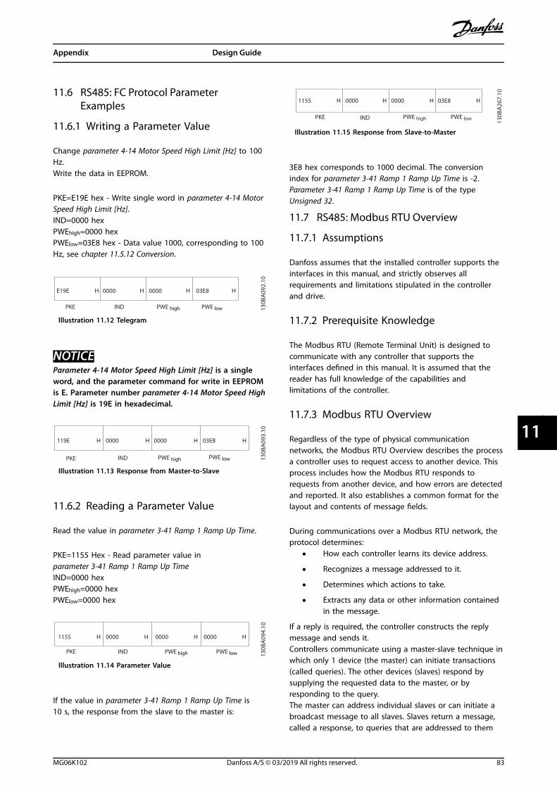
11.6 RS485: FC Protocol ParameterExamples
11.6.1 Writing a Parameter Value
Change parameter 4-14 Motor Speed High Limit [Hz] to 100Hz.Write the data in EEPROM.
PKE=E19E hex - Write single word in parameter 4-14 MotorSpeed High Limit [Hz].IND=0000 hexPWEhigh=0000 hexPWElow=03E8 hex - Data value 1000, corresponding to 100Hz, see chapter 11.5.12 Conversion.
E19E H
PKE IND PWE high PWE low
0000 H 0000 H 03E8 H
130B
A09
2.10
Illustration 11.12 Telegram
NOTICEParameter 4-14 Motor Speed High Limit [Hz] is a singleword, and the parameter command for write in EEPROMis E. Parameter number parameter 4-14 Motor Speed HighLimit [Hz] is 19E in hexadecimal.
119E H
PKE IND PWE high PWE low
0000 H 0000 H 03E8 H
130B
A09
3.10
Illustration 11.13 Response from Master-to-Slave
11.6.2 Reading a Parameter Value
Read the value in parameter 3-41 Ramp 1 Ramp Up Time.
PKE=1155 Hex - Read parameter value inparameter 3-41 Ramp 1 Ramp Up TimeIND=0000 hexPWEhigh=0000 hexPWElow=0000 hex
1155 H
PKE IND PWE high PWE low
0000 H 0000 H 0000 H
130B
A09
4.10
Illustration 11.14 Parameter Value
If the value in parameter 3-41 Ramp 1 Ramp Up Time is10 s, the response from the slave to the master is:
130B
A26
7.10
1155 H
PKE IND
0000 H 0000 H 03E8 H
PWE high PWE low
Illustration 11.15 Response from Slave-to-Master
3E8 hex corresponds to 1000 decimal. The conversionindex for parameter 3-41 Ramp 1 Ramp Up Time is -2.Parameter 3-41 Ramp 1 Ramp Up Time is of the typeUnsigned 32.
11.7 RS485: Modbus RTU Overview
11.7.1 Assumptions
Danfoss assumes that the installed controller supports theinterfaces in this manual, and strictly observes allrequirements and limitations stipulated in the controllerand drive.
11.7.2 Prerequisite Knowledge
The Modbus RTU (Remote Terminal Unit) is designed tocommunicate with any controller that supports theinterfaces defined in this manual. It is assumed that thereader has full knowledge of the capabilities andlimitations of the controller.
11.7.3 Modbus RTU Overview
Regardless of the type of physical communicationnetworks, the Modbus RTU Overview describes the processa controller uses to request access to another device. Thisprocess includes how the Modbus RTU responds torequests from another device, and how errors are detectedand reported. It also establishes a common format for thelayout and contents of message fields.
During communications over a Modbus RTU network, theprotocol determines:
• How each controller learns its device address.
• Recognizes a message addressed to it.
• Determines which actions to take.
• Extracts any data or other information containedin the message.
If a reply is required, the controller constructs the replymessage and sends it.Controllers communicate using a master-slave technique inwhich only 1 device (the master) can initiate transactions(called queries). The other devices (slaves) respond bysupplying the requested data to the master, or byresponding to the query.The master can address individual slaves or can initiate abroadcast message to all slaves. Slaves return a message,called a response, to queries that are addressed to them
Appendix Design Guide
MG06K102 Danfoss A/S © 03/2019 All rights reserved. 83
11 11

individually. No responses are returned to broadcastqueries from the master. The Modbus RTU protocolestablishes the format for the master query by placing intoit the device (or broadcast) address, a function codedefining the requested action, any data to send, and anerror-checking field. The slave response message is alsoconstructed using Modbus protocol. It contains fieldsconfirming the action taken, any data to return, and anerror-checking field. If an error occurs in receipt of themessage, or if the slave is unable to perform the requestedaction, the slave constructs an error message, which itsends in response, or a timeout occurs.
11.7.4 Drive with Modbus RTU
The drive communicates in Modbus RTU format over thebuilt-in RS485 interface. Modbus RTU provides access tothe control word and bus reference of the drive.
The control word allows the Modbus master to controlseveral important functions of the drive:
• Start.
• Stop of the drive in various ways:Coast stop.Quick stop.DC brake stop.Normal (ramp) stop.
• Reset after a fault trip.
• Run at various preset speeds.
• Run in reverse.
• Change the active set-up.
• Control the built-in relay of the drive.
The bus reference is commonly used for speed control. It isalso possible to access the parameters, read their values,and, where possible, write values to them, allowing arange of control options, including controlling the setpointof the drive when its internal PI controller is used.
11.7.5 Drive with Modbus RTU
To enable Modbus RTU on the drive, set the followingparameters:
Parameter Setting
Parameter 8-30 Protocol Modbus RTU
Parameter 8-31 Address 1–247
Parameter 8-32 Baud Rate 2400–115200
Parameter 8-33 Parity /Stop Bits
Even parity, 1 stop bit (default)
11.7.6 Drive with Modbus RTU
The controllers are set up to communicate on the Modbusnetwork using RTU mode, with each byte in a messagecontaining 2 4-bit hexadecimal characters. The format foreach byte is shown in Table 11.10.
Startbit
Data byte Stop/parity
Stop
Table 11.10 Example Format
Coding system 8-bit binary, hexadecimal 0–9, A–F. 2hexadecimal characters contained in each 8-bit field of the message.
Bits per byte 1 start bit.8 data bits, least significant bit sent first.1 bit for even/odd parity; no bit for noparity.1 stop bit if parity is used; 2 bits if noparity.
Error check field CRC (cyclical redundancy check)
Table 11.11 Bit Detail
11.8 RS485: Modbus RTU TelegramStructure
11.8.1 Modbus RTU Telegram Structure
The transmitting device places a Modbus RTU messageinto a frame with a known beginning and ending point.Receiving devices are able to begin at the start of themessage, read the address portion, determine whichdevice is addressed (or all devices, if the message isbroadcast), and to recognize when the message iscompleted. Partial messages are detected and errors set asa result. Characters for transmission must be inhexadecimal 00–FF format in each field. The drive contin-uously monitors the network bus, also during silentintervals. When the 1st field (the address field) is received,each drive or device decodes it to determine which deviceis being addressed. Modbus RTU messages addressed to 0are broadcast messages. No response is allowed forbroadcast messages. A typical message frame is shown inTable 11.12.
Start Address Function Data CRCcheck
End
T1-T2-T3-T4
8 bits 8 bits N x 8 bits 16 bits T1-T2-T3-T4
Table 11.12 Typical Modbus RTU Telegram Structure
Appendix VLT® AutomationDrive FC 361
84 Danfoss A/S © 03/2019 All rights reserved. MG06K102
1111

11.8.2 Start/Stop Field
Messages start with a silent period of at least 3.5 characterintervals, implemented as a multiple of character intervalsat the selected network baud rate (shown as start T1-T2-T3-T4). The 1st transmitted field is the device address.Following the last transmitted character, a similar period ofat least 3.5 character intervals marks the end of themessage. A new message can begin after this period. Theentire message frame must be transmitted as a continuousstream. If a silent period of more than 1.5 characterintervals occurs before completion of the frame, thereceiving device flushes the incomplete message andassumes that the next byte is the address field of a newmessage. Similarly, if a new message begins before 3.5character intervals after a previous message, the receivingdevice considers it a continuation of the previous message,causing a timeout (no response from the slave), since thevalue in the final CRC (cyclical redundancy check) field isnot valid for the combined messages.
11.8.3 Address Field
The address field of a message frame contains 8 bits. Validslave device addresses are in the range of 0–247 decimal.The individual slave devices are assigned addresses in therange of 1–247 (0 is reserved for broadcast mode, which allslaves recognize). A master addresses a slave by placingthe slave address in the address field of the message.When the slave sends its response, it places its ownaddress in this address field to let the master know whichslave is responding.
11.8.4 Function Field
The function field of a message frame contains 8 bits. Validcodes are in the range of 1–FF. Function fields are used tosend messages between master and slave. When amessage is sent from a master to a slave device, thefunction code field tells the slave what action to perform.When the slave responds to the master, it uses thefunction code field to indicate either a normal (error-free)response, or that an error has occurred (called anexception response). For a normal response, the slavesimply echoes the original function code. For an exceptionresponse, the slave returns a code that is equivalent to theoriginal function code with its most significant bit set tologic 1. In addition, the slave places a unique code into thedata field of the response message. This code tells themaster what error occurred, or the reason for theexception. See chapter 11.9.1 Function Codes Supported byModbus RTU.
11.8.5 Data Field
The data field is constructed using sets of 2 hexadecimaldigits, in the range of 00–FF hexadecimal. These sequencesare made up of 1 RTU character. The data field ofmessages sent from a master-to-slave device contains moreinformation, which the slave must use to do what isdefined by the function code. This information can includeitems such as coil or register addresses, the quantity ofitems, and the count of actual data bytes in the field.
11.8.6 CRC Check Field
Messages include an error-checking field, operating basedon a CRC (cyclical redundancy check) method. The CRCfield checks the contents of the entire message. It isapplied regardless of any parity check method used for theindividual characters of the message. The transmittingdevice calculates the CRC value then appends the CRC asthe last field in the message. The receiving devicerecalculates a CRC during receipt of the message andcompares the calculated value to the actual value receivedin the CRC field. If the 2 values are unequal, a bus timeoutresults. The error-checking field contains a 16-bit binaryvalue implemented as 2 8-bit bytes. After error-checking,the low-order byte of the field is appended first, followedby the high-order byte. The CRC high-order byte is the lastbyte sent in the message.
11.8.7 Coil Register Addressing
In Modbus, all data are organized in coils and holdingregisters. Coils hold a single bit, whereas holding registershold a 2 byte word (16 bits). All data addresses in Modbusmessages are referenced to 0. The 1st occurrence of a dataitem is addressed as item number 0. For example: The coilknown as coil 1 in a programmable controller is addressedas coil 0000 in the data address field of a Modbusmessage. Coil 127 decimal is addressed as coil 007Ehex(126 decimal).Holding register 40001 is addressed as register 0000 in thedata address field of the message. The function code fieldalready specifies a holding register operation. Therefore,the 4XXXX reference is implicit. Holding register 40108 isaddressed as register 006Bhex (107 decimal).
Appendix Design Guide
MG06K102 Danfoss A/S © 03/2019 All rights reserved. 85
11 11

Coil number Description Signal direction
1–16 Drive control word (see Table 11.14). Master-to-slave
17–32 Drive speed or setpoint reference range 0x0–0xFFFF (-200% ... ~200%). Master-to-slave
33–48 Drive status word (see Table 11.14). Master-to-slave
49–64 Open-loop mode: Drive output frequency.Closed-loop mode: Drive feedback signal.
Slave-to-master
65 Parameter write control (master-to-slave).
Master-to-slave0 = Parameter changes are written to the RAM of the drive.
1 = Parameter changes are written to the RAM and EEPROM of the drive.
66–65536 Reserved.
Table 11.13 Coils and Holding Registers
Coil 0 1
01 Preset reference LSB
02 Preset reference MSB
03 DC brake No DC brake
04 Coast stop No coast stop
05 Quick stop No quick stop
06 Freeze frequency No freeze frequency
07 Ramp stop Start
08 No reset Reset
09 No jog Jog
10 Ramp 1 Ramp 2
11 Data not valid Data valid
12 Relay 1 off Relay 1 on
13 Relay 2 off Relay 2 on
14 Set up LSB
15 Set up MSB
16 No reversing Reversing
Table 11.14 Drive Control Word (FC Profile)
Coil 0 1
33 Control not ready Control ready
34 Drive not ready Drive ready
35 Coasting stop Safety closed
36 No alarm Alarm
37 Not used Not used
38 Not used Not used
39 Not used Not used
40 No warning Warning
41 Not at reference At reference
42 Hand mode Auto mode
43 Out of frequency range In frequency range
44 Stopped Running
45 Not used Not used
46 No voltage warning Voltage warning
47 Not in current limit Current limit
48 No thermal warning Thermal warning
Table 11.15 Drive Status Word (FC Profile)
Registernumber
Description
00001–00006 Reserved.
00007 Last fault code from an FC data object interface.
00008 Reserved.
00009 Parameter index1).
00010–00990 000 parameter group (parameters 001–099).
01000–01990 100 parameter group (parameters 100–199).
02000–02990 200 parameter group (parameters 200–299).
03000–03990 300 parameter group (parameters 300–399).
04000–04990 400 parameter group (parameters 400–499).
... ...
49000–49990 4900 parameter group (parameters 4900–4999).
50000 Input data: Drive control word register (CTW).
50010 Input data: Bus reference register (REF).
... ...
50200 Output data: Drive status word register (STW).
50210 Output data: Drive main actual value register (MAV).
Table 11.16 Holding Registers
1) Used to specify the index number used when accessing an indexed parameter.
Appendix VLT® AutomationDrive FC 361
86 Danfoss A/S © 03/2019 All rights reserved. MG06K102
1111

11.9 RS485: Modbus RTU Message FunctionCodes
11.9.1 Function Codes Supported byModbus RTU
Modbus RTU supports use of the function codes inTable 11.17 in the function field of a message.
Function Function code
Read coils 1 hex
Read holding registers 3 hex
Write single coil 5 hex
Write single register 6 hex
Write multiple coils F hex
Write multiple registers 10 hex
Get comm. event counter B hex
Report slave ID 11 hex
Table 11.17 Function Codes
Function Functioncode
Sub-functioncode
Sub-function
Diagnostics 8 1 Restart communication.
2 Return diagnostic register.
10 Clear counters anddiagnostic register.
11 Return bus message count.
12 Return bus communicationerror count.
13 Return bus exception errorcount.
14 Return slave messagecount.
Table 11.18 Function Codes
11.9.2 Modbus Exception Codes
For a full explanation of the structure of an exception coderesponse, refer to chapter 11.8 RS485: Modbus RTU TelegramStructure.
Code Name Meaning
1 Illegalfunction
The function code received in the query isnot an allowable action for the server (orslave). This code can be because thefunction code is only applicable to newerdevices and was not implemented in theunit selected. It could also indicate thatthe server (or slave) is in the wrong stateto process a request of this type, forexample because it is not configured andis being asked to return register values.
2 Illegal dataaddress
The data address received in the query isnot an allowable address for the server(or slave). More specifically, thecombination of reference number andtransfer length is invalid. For a controllerwith 100 registers, a request with offset96 and length 4 would succeed, a requestwith offset 96 and length 5 generatesexception 02.
3 Illegal datavalue
A value contained in the query data fieldis not an allowable value for server (orslave). This code indicates a fault in thestructure of the remainder of a complexrequest, such as that the implied length isincorrect. It specifically does NOT meanthat a data item submitted for storage ina register has a value outside theexpectation of the application program,since the Modbus protocol is unaware ofthe significance of any particular value ofany particular register.
4 Slave devicefailure
An unrecoverable error occurred while theserver (or slave) was attempting toperform the requested action.
Table 11.19 Modbus Exception Codes
Appendix Design Guide
MG06K102 Danfoss A/S © 03/2019 All rights reserved. 87
11 11

11.10 RS485: Modbus RTU Parameters
11.10.1 Parameter Handling
The PNU (parameter number) is translated from theregister address contained in the Modbus read or writemessage. The parameter number is translated to Modbusas (10xparameter number) DECIMAL.
11.10.2 Storage of Data
The coil 65 decimal determines whether data written tothe drive is stored in EEPROM and RAM (coil 65=1) or onlyin RAM (coil 65=0).
11.10.3 IND
The array index is set in holding register 9 and used whenaccessing array parameters.
11.10.4 Text Blocks
Parameters stored as text strings are accessed in the sameway as the other parameters. The maximum text block sizeis 20 characters. If a read request for a parameter is formore characters than the parameter stores, the response istruncated. If the read request for a parameter is for fewercharacters than the parameter stores, the response is spacefilled.
11.10.5 Conversion Factor
Since a parameter value can only be transferred as a wholenumber, a conversion factor must be used to transferdecimals. See chapter 11.6 RS485: FC Protocol ParameterExamples.
11.10.6 Parameter Values
Standard data typesStandard data types are int16, int32, uint8, uint16, anduint32. They are stored as 4x registers (40001–4FFFF). Theparameters are read using function 03 hex read holdingregisters. Parameters are written using the function 6 hexpreset single register for 1 register (16 bits), and thefunction 10 hex preset multiple registers for 2 registers (32bits). Readable sizes range from 1 register (16 bits) up to10 registers (20 characters).
Non-standard data typesNon-standard data types are text strings and are stored as4x registers (40001–4FFFF). The parameters are read usingfunction 03 hex Read holding registers and written usingfunction 10 hex Preset multiple registers. Readable sizesrange from 1 register (2 characters) up to 10 registers (20characters).
11.11 RS485: FC Control Profile
11.11.1 Control Word According to FCProfile
Speed ref.CTW
Master-follower
130B
A27
4.11
15 14 13 12 11 10 9 8 7 6 5 4 3 2 1 0Bitno.:
Illustration 11.16 CW Master-to-Slave
Bit Bit value = 0 Bit value = 1
00 Reference value External selection lsb
01 Reference value External selection msb
02 DC brake Ramp
03 Coasting No coasting
04 Quick stop Ramp
05 Hold output frequency Use ramp
06 Ramp stop Start
07 No function Reset
08 No function Jog
09 Ramp 1 Ramp 2
10 Data invalid Data valid
11 No function Relay 01 active
12 No function Relay 02 active
13 Parameter set-up Selection lsb
14 Parameter set-up Selection msb
15 No function Reverse
Explanation of the control bitsBits 00/01Bits 00 and 01 are used to select between the 4 referencevalues, which are pre-programmed in parameter 3-10 PresetReference according to Table 11.20.
Programmedreference value
Parameter Bit 01 Bit 00
1 [0]parameter 3-10 Preset Reference
0 0
2 [1]parameter 3-10 Preset Reference
0 1
3 [2]parameter 3-10 Preset Reference
1 0
4 [3]parameter 3-10 Preset Reference
1 1
Table 11.20 Control Bits
Appendix VLT® AutomationDrive FC 361
88 Danfoss A/S © 03/2019 All rights reserved. MG06K102
1111

NOTICEMake a selection in parameter 8-56 Preset Reference Selectto define how bit 00/01 gates with the correspondingfunction on the digital inputs.
Bit 02, DC brakeBit 02=0 leads to DC braking and stop. Set braking currentand duration in parameter 2-01 DC Brake Current andparameter 2-02 DC Braking Time.Bit 02=1 leads to ramping.
Bit 03, CoastingBit 03=0: The drive immediately shuts off the outputtransistors and the motor coasts to a standstill.Bit 03=1: The drive starts the motor if the other startingconditions are met.
Make a selection in parameter 8-50 Coasting Select todefine how bit 03 gates with the corresponding functionon a digital input.
Bit 04, Quick stopBit 04=0: Makes the motor speed ramp down to stop (setin parameter 3-81 Quick Stop Ramp Time).
Bit 05, Hold output frequencyBit 05=0: The present output frequency (in Hz) freezes.Change the frozen output frequency only with the digitalinputs found in parameter 5-10 Terminal 18 Digital Input –parameter 5-15 Terminal 33 Digital Input.
NOTICEIf freeze output is active, only the following conditionscan stop the drive:
• Bit 03 Coasting stop.
• Bit 02 DC braking.
• Digital input (parameter 5-10 Terminal 18 DigitalInput – parameter 5-15 Terminal 33 Digital Input)programmed to DC braking, Coasting stop, orReset and Coasting stop.
Bit 06, Ramp stop/startBit 06=0: Causes a stop and makes the motor speed rampdown to stop via the selected ramp down parameter.Bit 06=1: Allows the drive to start the motor if the otherstarting conditions are met.
Make a selection in parameter 8-53 Start Select to definehow bit 06 Ramp stop/start gates with the correspondingfunction on a digital input.
Bit 07, ResetBit 07=0: No reset.Bit 07=1: Resets a trip. Reset is activated on the leadingedge of the signal, that is, when changing from logic 0 tologic 1.
Bit 08, JogBit 08=1: The output frequency depends onparameter 3-19 Jog Speed [RPM].
Bit 09, Selection of ramp 1/2Bit 09=0: Ramp 1 is active (parameter 3-41 Ramp 1 RampUp Time – parameter 3-42 Ramp 1 Ramp Down Time).Bit 09=1: Ramp 2 (parameter 3-51 Ramp 2 Ramp Up Time –parameter 3-52 Ramp 2 Ramp Down Time) is active.
Bit 10, Data not valid/Data validTell the drive whether to use or ignore the control word.Bit 10=0: The control word is ignored.Bit 10=1: The control word is used. This function is relevantbecause the telegram always contains the control wordregardless of the telegram type. Thus, it is possible to turnoff the control word if not in use when updating orreading parameters.
Bit 11, Relay 01Bit 11=0: Relay not activated.Bit 11=1: Relay 01 activated if [36] Control word bit 11 isselected in parameter 5-40 Function Relay.
Bit 12, Relay 04Bit 12=0: Relay 04 is not activated.Bit 12=1: Relay 04 is activated if [37] Control word bit 12 isselected in parameter 5-40 Function Relay.
Bit 13/14, Selection of set-upUse bits 13 and 14 to select from the 4 menu set-upsaccording to Table 11.21.
Set-up Bit 14 Bit 13
1 0 0
2 0 1
3 1 0
4 1 1
Table 11.21 Selection of Set-Up
The function is only possible when [9] Multi Set-ups isselected in parameter 0-10 Active Set-up.
Make a selection in parameter 8-55 Set-up Select to definehow bit 13/14 gates with the corresponding function onthe digital inputs.
Bit 15 ReverseBit 15=0: No reversing.Bit 15=1: Reversing. In the default setting, reversing is setto [0] Digital input in parameter 8-54 Reversing Select. Bit 15causes reversing only when the following is selected:
• Serial communication.
• Logic or.
• Logic and.
Appendix Design Guide
MG06K102 Danfoss A/S © 03/2019 All rights reserved. 89
11 11
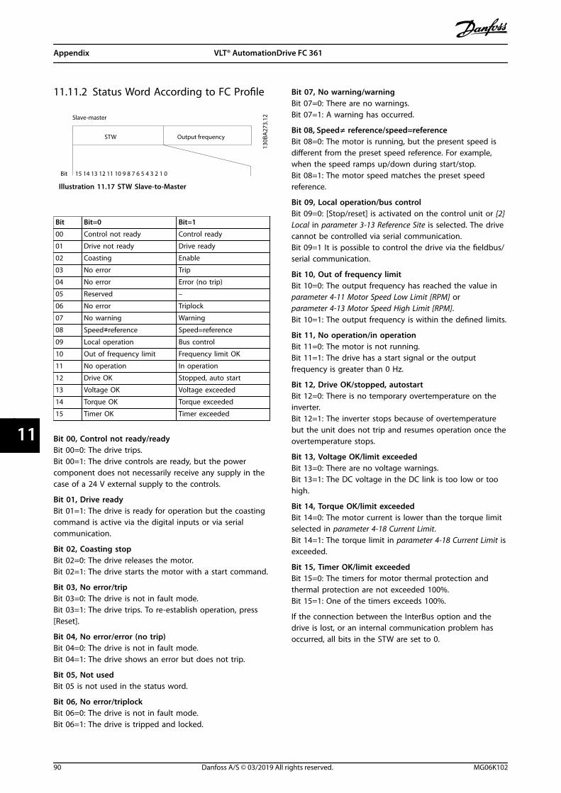
11.11.2 Status Word According to FC Profile
Output frequencySTW
Bit
Slave-master
15 14 13 12 11 10 9 8 7 6 5 4 3 2 1 0
130B
A27
3.12
Illustration 11.17 STW Slave-to-Master
Bit Bit=0 Bit=1
00 Control not ready Control ready
01 Drive not ready Drive ready
02 Coasting Enable
03 No error Trip
04 No error Error (no trip)
05 Reserved –
06 No error Triplock
07 No warning Warning
08 Speed≠reference Speed=reference
09 Local operation Bus control
10 Out of frequency limit Frequency limit OK
11 No operation In operation
12 Drive OK Stopped, auto start
13 Voltage OK Voltage exceeded
14 Torque OK Torque exceeded
15 Timer OK Timer exceeded
Bit 00, Control not ready/readyBit 00=0: The drive trips.Bit 00=1: The drive controls are ready, but the powercomponent does not necessarily receive any supply in thecase of a 24 V external supply to the controls.
Bit 01, Drive readyBit 01=1: The drive is ready for operation but the coastingcommand is active via the digital inputs or via serialcommunication.
Bit 02, Coasting stopBit 02=0: The drive releases the motor.Bit 02=1: The drive starts the motor with a start command.
Bit 03, No error/tripBit 03=0: The drive is not in fault mode.Bit 03=1: The drive trips. To re-establish operation, press[Reset].
Bit 04, No error/error (no trip)Bit 04=0: The drive is not in fault mode.Bit 04=1: The drive shows an error but does not trip.
Bit 05, Not usedBit 05 is not used in the status word.
Bit 06, No error/triplockBit 06=0: The drive is not in fault mode.Bit 06=1: The drive is tripped and locked.
Bit 07, No warning/warningBit 07=0: There are no warnings.Bit 07=1: A warning has occurred.
Bit 08, Speed≠ reference/speed=referenceBit 08=0: The motor is running, but the present speed isdifferent from the preset speed reference. For example,when the speed ramps up/down during start/stop.Bit 08=1: The motor speed matches the preset speedreference.
Bit 09, Local operation/bus controlBit 09=0: [Stop/reset] is activated on the control unit or [2]Local in parameter 3-13 Reference Site is selected. The drivecannot be controlled via serial communication.Bit 09=1 It is possible to control the drive via the fieldbus/serial communication.
Bit 10, Out of frequency limitBit 10=0: The output frequency has reached the value inparameter 4-11 Motor Speed Low Limit [RPM] orparameter 4-13 Motor Speed High Limit [RPM].Bit 10=1: The output frequency is within the defined limits.
Bit 11, No operation/in operationBit 11=0: The motor is not running.Bit 11=1: The drive has a start signal or the outputfrequency is greater than 0 Hz.
Bit 12, Drive OK/stopped, autostartBit 12=0: There is no temporary overtemperature on theinverter.Bit 12=1: The inverter stops because of overtemperaturebut the unit does not trip and resumes operation once theovertemperature stops.
Bit 13, Voltage OK/limit exceededBit 13=0: There are no voltage warnings.Bit 13=1: The DC voltage in the DC link is too low or toohigh.
Bit 14, Torque OK/limit exceededBit 14=0: The motor current is lower than the torque limitselected in parameter 4-18 Current Limit.Bit 14=1: The torque limit in parameter 4-18 Current Limit isexceeded.
Bit 15, Timer OK/limit exceededBit 15=0: The timers for motor thermal protection andthermal protection are not exceeded 100%.Bit 15=1: One of the timers exceeds 100%.
If the connection between the InterBus option and thedrive is lost, or an internal communication problem hasoccurred, all bits in the STW are set to 0.
Appendix VLT® AutomationDrive FC 361
90 Danfoss A/S © 03/2019 All rights reserved. MG06K102
1111
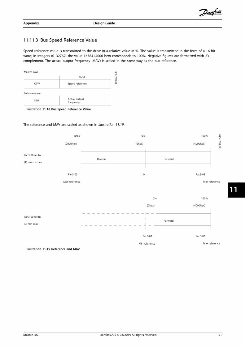
11.11.3 Bus Speed Reference Value
Speed reference value is transmitted to the drive in a relative value in %. The value is transmitted in the form of a 16-bitword; in integers (0–32767) the value 16384 (4000 hex) corresponds to 100%. Negative figures are formatted with 2’scomplement. The actual output frequency (MAV) is scaled in the same way as the bus reference.
Actual outputfrequency
STW
Follower-slave
Speed referenceCTW
Master-slave
16bit
130B
A27
6.11
Illustration 11.18 Bus Speed Reference Value
The reference and MAV are scaled as shown in Illustration 11.19.
Reverse ForwardPar.3-00 set to
(1) -max- +max
Max reference Max reference
Par.3-00 set to
(0) min-max
Max reference
Forward
Min reference
100%
(4000hex)
-100%
(C000hex)
0%
(0hex)
Par.3-03 0 Par.3-03
Par.3-03
(4000hex)(0hex)
0% 100%
Par.3-02
130B
A27
7.10
Illustration 11.19 Reference and MAV
Appendix Design Guide
MG06K102 Danfoss A/S © 03/2019 All rights reserved. 91
11 11
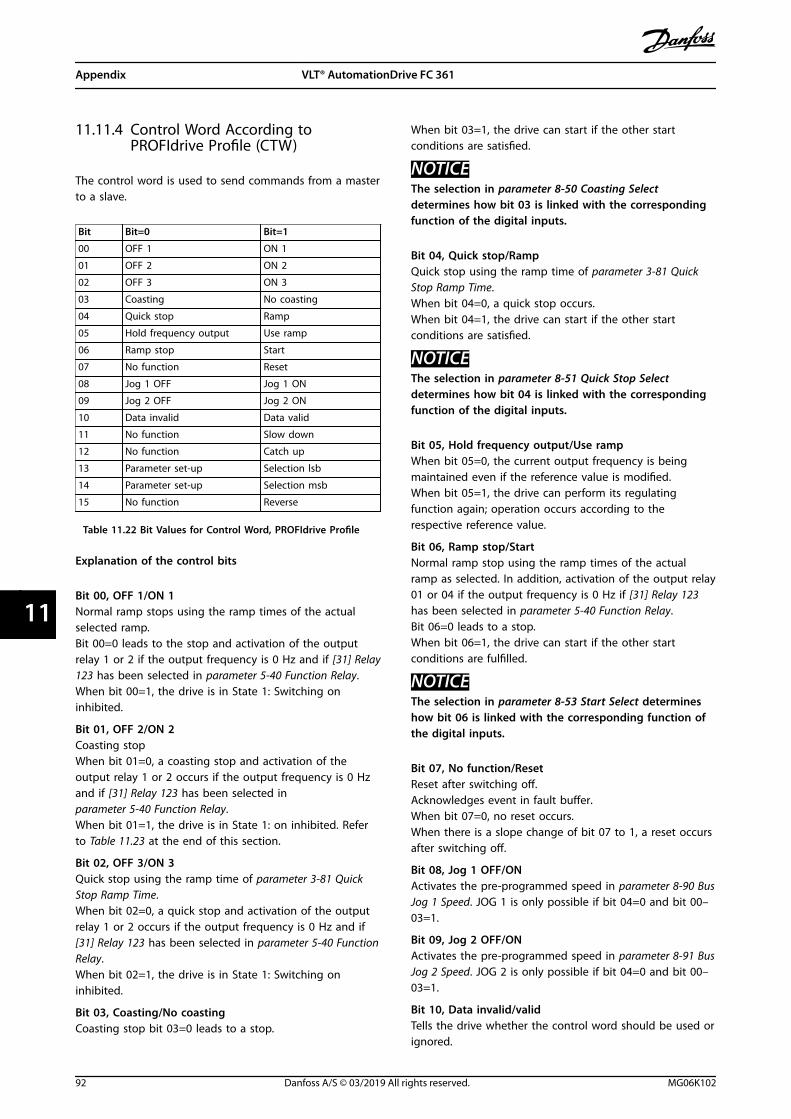
11.11.4 Control Word According toPROFIdrive Profile (CTW)
The control word is used to send commands from a masterto a slave.
Bit Bit=0 Bit=1
00 OFF 1 ON 1
01 OFF 2 ON 2
02 OFF 3 ON 3
03 Coasting No coasting
04 Quick stop Ramp
05 Hold frequency output Use ramp
06 Ramp stop Start
07 No function Reset
08 Jog 1 OFF Jog 1 ON
09 Jog 2 OFF Jog 2 ON
10 Data invalid Data valid
11 No function Slow down
12 No function Catch up
13 Parameter set-up Selection lsb
14 Parameter set-up Selection msb
15 No function Reverse
Table 11.22 Bit Values for Control Word, PROFIdrive Profile
Explanation of the control bits
Bit 00, OFF 1/ON 1Normal ramp stops using the ramp times of the actualselected ramp.Bit 00=0 leads to the stop and activation of the outputrelay 1 or 2 if the output frequency is 0 Hz and if [31] Relay123 has been selected in parameter 5-40 Function Relay.When bit 00=1, the drive is in State 1: Switching oninhibited.
Bit 01, OFF 2/ON 2Coasting stopWhen bit 01=0, a coasting stop and activation of theoutput relay 1 or 2 occurs if the output frequency is 0 Hzand if [31] Relay 123 has been selected inparameter 5-40 Function Relay.When bit 01=1, the drive is in State 1: on inhibited. Referto Table 11.23 at the end of this section.
Bit 02, OFF 3/ON 3Quick stop using the ramp time of parameter 3-81 QuickStop Ramp Time.When bit 02=0, a quick stop and activation of the outputrelay 1 or 2 occurs if the output frequency is 0 Hz and if[31] Relay 123 has been selected in parameter 5-40 FunctionRelay.When bit 02=1, the drive is in State 1: Switching oninhibited.
Bit 03, Coasting/No coastingCoasting stop bit 03=0 leads to a stop.
When bit 03=1, the drive can start if the other startconditions are satisfied.
NOTICEThe selection in parameter 8-50 Coasting Selectdetermines how bit 03 is linked with the correspondingfunction of the digital inputs.
Bit 04, Quick stop/RampQuick stop using the ramp time of parameter 3-81 QuickStop Ramp Time.When bit 04=0, a quick stop occurs.When bit 04=1, the drive can start if the other startconditions are satisfied.
NOTICEThe selection in parameter 8-51 Quick Stop Selectdetermines how bit 04 is linked with the correspondingfunction of the digital inputs.
Bit 05, Hold frequency output/Use rampWhen bit 05=0, the current output frequency is beingmaintained even if the reference value is modified.When bit 05=1, the drive can perform its regulatingfunction again; operation occurs according to therespective reference value.
Bit 06, Ramp stop/StartNormal ramp stop using the ramp times of the actualramp as selected. In addition, activation of the output relay01 or 04 if the output frequency is 0 Hz if [31] Relay 123has been selected in parameter 5-40 Function Relay.Bit 06=0 leads to a stop.When bit 06=1, the drive can start if the other startconditions are fulfilled.
NOTICEThe selection in parameter 8-53 Start Select determineshow bit 06 is linked with the corresponding function ofthe digital inputs.
Bit 07, No function/ResetReset after switching off.Acknowledges event in fault buffer.When bit 07=0, no reset occurs.When there is a slope change of bit 07 to 1, a reset occursafter switching off.
Bit 08, Jog 1 OFF/ONActivates the pre-programmed speed in parameter 8-90 BusJog 1 Speed. JOG 1 is only possible if bit 04=0 and bit 00–03=1.
Bit 09, Jog 2 OFF/ONActivates the pre-programmed speed in parameter 8-91 BusJog 2 Speed. JOG 2 is only possible if bit 04=0 and bit 00–03=1.
Bit 10, Data invalid/validTells the drive whether the control word should be used orignored.
Appendix VLT® AutomationDrive FC 361
92 Danfoss A/S © 03/2019 All rights reserved. MG06K102
1111

Bit 10=0 causes the control word to be ignored.Bit 10=1 causes the control word to be used. This functionis relevant because the control word is always contained inthe telegram, regardless of which type of telegram is used.For example, it is possible to turn off the control word if itis not intended to be used with updating or readingparameters.
Bit 11, No function/slow downReduces the speed reference value by the amount given inparameter 3-12 Catch up/slow Down Value.When bit 11=0, no modification of the reference valueoccurs. When bit 11=1, the reference value is reduced.
Bit 12, No function/catch upIncreases the speed reference value by the amount givenin parameter 3-12 Catch up/slow Down Value.When bit 12=0, no modification of the reference valueoccurs.When bit 12=1, the reference value is increased.If both slowing down and accelerating are activated (bits11 and 12=1), slowing down has priority, for example thespeed reference value is reduced.
Bits 13/14, Set-up selectionSelects between the 4 parameter set-ups according toTable 11.23.
The function is only possible if [9] Multi Set-up has beenselected in parameter 0-10 Active Set-up. The selection inparameter 8-55 Set-up Select determines how bits 13 and14 are linked with the corresponding function of thedigital inputs. Changing set-up while running is onlypossible if the set-ups have been linked inparameter 0-12 This Set-up Linked to.
Set-up Bit 13 Bit 14
1 0 0
2 1 0
3 0 1
4 1 1
Table 11.23 Bits 13/14 Set-up Options
Bit 15, No function/ReverseBit 15=0 causes no reversing.Bit 15=1 causes reversing.Note: In the factory setting, reversing is set to [0] Digitalinput in parameter 8-54 Reversing Select.
NOTICEBit 15 causes reversing only when the following isselected:
• Serial communication.
• Logic or.
• Logic and.
11.11.5 Status Word According toPROFIdrive Profile (STW)
The status word notifies a master about the status of aslave.
Bit Bit=0 Bit=1
00 Control not ready Control ready
01 Drive not ready Drive ready
02 Coasting Enable
03 No error Trip
04 OFF 2 ON 2
05 OFF 3 ON 3
06 Start possible Start not possible
07 No warning Warning
08 Speed ≠ reference Speed = reference
09 Local operation Bus control
10 Out of frequency limit Frequency limit ok
11 No operation In operation
12 Drive OK Stopped, auto start
13 Voltage OK Voltage exceeded
14 Torque OK Torque exceeded
15 Timer OK Timer exceeded
Table 11.24 Bit Values for Status Word, PROFIdrive Profile
Explanation of the status bits
Bit 00, Control not ready/readyWhen bit 00=0, bit 00, 01 or 02 of the control word is 0(OFF 1, OFF 2 or OFF 3) - or the drive is switched off (trip).When bit 00=1, the drive control is ready, but supply tothe unit is not necessarily present (in the event of 24 Vexternal supply to the control system).
Bit 01, VLT not ready/readySame significance as bit 00, however, there is a supply ofthe power unit. The drive is ready when it receives thenecessary start signals.
Bit 02, Coasting/enableWhen bit 02=0, bit 00, 01, or 02 of the control word is 0(OFF 1, OFF 2 or OFF 3 or coasting) - or the drive isswitched off (trip).When bit 02=1, bit 00, 01, or 02 of the control word is 1;the drive has not tripped.
Bit 03, No error/tripWhen bit 03=0, no error condition of the drive exists.When bit 03=1, the drive has tripped and requires a resetsignal before it can start.
Bit 04, ON 2/OFF 2When bit 01 of the control word is 0, then bit 04=0.When bit 01 of the control word is 1, then bit 04=1.
Bit 05, ON 3/OFF 3When bit 02 of the control word is 0, then bit 05=0.When bit 02 of the control word is 1, then bit 05=1.
Appendix Design Guide
MG06K102 Danfoss A/S © 03/2019 All rights reserved. 93
11 11
Bit 06, Start possible/start not possibleIf [1] PROFIdrive profile is selected in parameter 8-10 ControlWord Profile, bit 06 is 1 after a switch-off acknowl-edgement, after activation of OFF2 or OFF3, and afterswitching on the mains voltage. Start not possible is resetwith bit 00 of the control word being set to 0 and bit 01,02, and 10 being set to 1.
Bit 07, No warning/WarningBit 07=0 means that there are no warnings.Bit 07=1 means that a warning has occurred.
Bit 08, Speed ≠ reference/speed = referenceWhen bit 08=0, the current speed of the motor deviatesfrom the set speed reference value. This scenario canoccur, for example, when the speed is being changedduring start/stop through ramp up/down.When bit 08=1, the current speed of the motorcorresponds to the set speed reference value.
Bit 09, Local operation/bus controlBit 09=0 indicates that the drive is stopped with the [Stop]key on the LCP, or that option [2] Linked to Hand/Auto or[0] Local is selected in parameter 3-13 Reference Site.When bit 09=1, the drive can be controlled through theserial interface.
Bit 10, Out of frequency limit/frequency limit OKWhen bit 10=0, the output frequency is outside the limitsset in parameter 4-52 Warning Speed Low andparameter 4-53 Warning Speed High.When bit 10=1, the output frequency is within theindicated limits.
Bit 11, No operation/operationWhen bit 11=0, the motor does not turn.When bit 11=1, the drive has a start signal, or the outputfrequency is higher than 0 Hz.
Bit 12, Drive OK/stopped, auto startWhen bit 12=0, there is no temporary overloading of theinverter.When bit 12=1, the inverter has stopped due tooverloading. However, the drive has not switched off (trip)and will start again after the overloading has ended.
Bit 13, Voltage OK/voltage exceededWhen bit 13=0, the voltage limits of the drive are notexceeded.When bit 13=1, the direct voltage in the intermediatecircuit of the drive is too low or too high.
Bit 14, Torque OK/torque exceededWhen bit 14=0, the motor torque is below the limitselected in parameter 4-16 Torque Limit Motor Mode andparameter 4-17 Torque Limit Generator Mode.When bit 14=1, the limit selected in parameter 4-16 TorqueLimit Motor Mode or parameter 4-17 Torque Limit GeneratorMode is exceeded.
Bit 15, Timer OK/timer exceededWhen bit 15=0, the timers for the motor thermalprotection and thermal drive protection have not exceeded100%.When bit 15=1, 1 of the timers has exceeded 100%.
Appendix VLT® AutomationDrive FC 361
94 Danfoss A/S © 03/2019 All rights reserved. MG06K102
1111
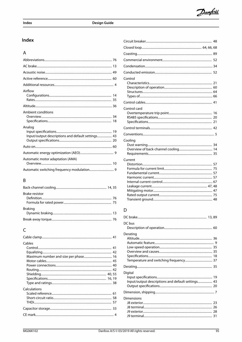
Index
AAbbreviations......................................................................................... 76
AC brake................................................................................................... 13
Acoustic noise........................................................................................ 49
Active reference.................................................................................... 60
Additional resources.............................................................................. 4
AirflowConfigurations.................................................................................. 14Rates..................................................................................................... 35
Altitude..................................................................................................... 36
Ambient conditionsOverview............................................................................................. 34Specifications.................................................................................... 18
AnalogInput specifications......................................................................... 19Input/output descriptions and default settings................... 43Output specifications..................................................................... 20
Auto on..................................................................................................... 60
Automatic energy optimization (AEO)............................................ 9
Automatic motor adaptation (AMA)Overview............................................................................................. 10
Automatic switching frequency modulation................................ 9
BBack-channel cooling................................................................... 14, 35
Brake resistorDefinition............................................................................................ 76Formula for rated power............................................................... 75
BrakingDynamic braking.............................................................................. 13
Break-away torque............................................................................... 76
CCable clamp............................................................................................ 41
CablesControl................................................................................................. 41Equalizing........................................................................................... 42Maximum number and size per phase..................................... 16Motor cables...................................................................................... 45Power connections.......................................................................... 40Routing................................................................................................ 42Shielding...................................................................................... 40, 55Specifications............................................................................. 16, 19Type and ratings............................................................................... 38
CalculationsScaled reference............................................................................... 61Short-circuit ratio............................................................................. 58THDi...................................................................................................... 57
Capacitor storage................................................................................. 33
CE mark....................................................................................................... 4
Circuit breaker....................................................................................... 48
Closed loop............................................................................... 64, 66, 68
Coasting................................................................................................... 89
Commercial environment................................................................. 52
Condensation......................................................................................... 34
Conducted emission........................................................................... 52
ControlCharacteristics................................................................................... 21Description of operation............................................................... 60Structures............................................................................................ 64Types of................................................................................................ 66
Control cables........................................................................................ 41
Control cardOvertemperature trip point......................................................... 16RS485 specifications....................................................................... 20Specifications.................................................................................... 21
Control terminals.................................................................................. 42
Conventions.............................................................................................. 5
CoolingDust warning..................................................................................... 34Overview of back-channel cooling............................................ 14Requirements.................................................................................... 35
CurrentDistortion............................................................................................ 57Formula for current limit............................................................... 75Fundamental current...................................................................... 57Harmonic current............................................................................. 57Internal current control.................................................................. 67Leakage current......................................................................... 47, 48Mitigating motor.............................................................................. 47Rated output current...................................................................... 75Transient ground.............................................................................. 48
DDC brake........................................................................................... 13, 89
DC busDescription of operation............................................................... 60
DeratingAltitude................................................................................................ 36Automatic feature.............................................................................. 9Low-speed operation..................................................................... 35Overview and causes...................................................................... 35Specifications.................................................................................... 18Temperature and switching frequency.................................... 37
Derating................................................................................................... 35
DigitalInput specifications......................................................................... 19Input/output descriptions and default settings................... 43Output specifications..................................................................... 20
Dimension, shipping.............................................................................. 7
DimensionsJ8 exterior........................................................................................... 23J8 terminal.......................................................................................... 26J9 exterior........................................................................................... 28J9 terminal.......................................................................................... 31
Index Design Guide
MG06K102 Danfoss A/S © 03/2019 All rights reserved. 95

Directive, EMC.......................................................................................... 4
Directive, Low Voltage........................................................................... 4
Directive, Machinery.............................................................................. 4
Discharge time......................................................................................... 6
Disconnect.............................................................................................. 44
Document version.................................................................................. 4
DriveClearance requirements................................................................ 35Configurator...................................................................................... 72
DU/dtOverview............................................................................................. 50
Duct cooling........................................................................................... 35
Duty cycleDefinition............................................................................................ 76
EEfficiency
Calculation.......................................................................................... 49Formula for drive efficiency.......................................................... 75Specifications.................................................................................... 16Using AMA.......................................................................................... 10
Electrical specifications 380–480 V................................................ 17
Electromagnetic interference.......................................................... 10
Electronic thermal relay (ETR).......................................................... 38
EMCCompatibility..................................................................................... 54General aspects................................................................................ 51Installation.......................................................................................... 56Interference........................................................................................ 55RS485 installation precautions.................................................... 78Test results.......................................................................................... 52
EMC Directive........................................................................................... 4
Emission requirements....................................................................... 52
EncoderConfiguration.................................................................................... 71Definition............................................................................................ 76Determining encoder direction.................................................. 71VLT® Encoder Input MCB 102....................................................... 15
Energy efficiency class........................................................................ 18
Environment.................................................................................... 18, 34
ETR............................................................................................................. 11
Exterior dimensionsJ8............................................................................................................ 23J9............................................................................................................ 28
External alarm reset............................................................................. 70
FFans
Required airflow............................................................................... 35Temperature-controlled fans....................................................... 10
FC profile.................................................................................................. 88
FeedbackConversion.......................................................................................... 64Handling.............................................................................................. 63Signal.................................................................................................... 66
Fieldbus............................................................................................. 15, 42
FiltersRFI filter................................................................................................ 54Sine-wave filter................................................................................. 40
Flying start.............................................................................................. 11
FormulaCurrent limit....................................................................................... 75Drive efficiency................................................................................. 75Output current.................................................................................. 75Rated power of the brake resistor.............................................. 75
Fourier series analysis......................................................................... 57
Frequency bypass................................................................................. 11
FusesFor use with power connections................................................ 40Overcurrent protection warning................................................ 38Specifications.................................................................................... 44
GGalvanic isolation................................................................... 10, 20, 54
Gases......................................................................................................... 34
General purpose I/O module........................................................... 15
Grounding................................................................................. 10, 41, 48
HHand on.................................................................................................... 60
HarmonicsDefinition of power factor............................................................ 76EN standards...................................................................................... 58IEC standards..................................................................................... 58Overview............................................................................................. 57
Heat sinkCleaning.............................................................................................. 34Overtemperature trip point......................................................... 16Required airflow............................................................................... 35
HeaterUsage.................................................................................................... 34
High voltage warning............................................................................ 6
High-altitude installation................................................................... 55
Humidity.................................................................................................. 34
IImmunity requirements..................................................................... 53
Input specifications............................................................................. 19
InstallationElectrical.............................................................................................. 38Qualified personnel........................................................................... 6Requirements.................................................................................... 34
Insulation................................................................................................. 47
Inverter..................................................................................................... 60
Index VLT® AutomationDrive FC 361
96 Danfoss A/S © 03/2019 All rights reserved. MG06K102
IT grid........................................................................................................ 49
KKinetic back-up...................................................................................... 11
KitsDescriptions....................................................................................... 74Ordering numbers........................................................................... 74
LLeakage current................................................................................ 6, 47
Lifting........................................................................................................ 33
Load shareWarning.................................................................................................. 6
Low Voltage Directive........................................................................... 4
Low-speed operation.......................................................................... 35
MMachinery Directive............................................................................... 4
MainsDrop-out............................................................................................. 11Fluctuations....................................................................................... 10Supply specifications...................................................................... 18
Maintenance.......................................................................................... 34
ModbusMessage structure........................................................................... 84RTU message function codes...................................................... 87RTU overview..................................................................................... 83
Modulation......................................................................................... 9, 75
MotorBreak-away torque........................................................................... 76Cables..................................................................................... 40, 45, 47Full torque.......................................................................................... 11Insulation............................................................................................ 47Leakage current................................................................................ 47Missing phase detection.................................................................. 8Mitigating bearing currents......................................................... 47thermal protection.......................................................................... 10Output specifications..................................................................... 18Parallel connection.......................................................................... 45Rotation............................................................................................... 45Thermistor.......................................................................................... 71Wiring schematic............................................................................. 39
Mounting configurations.................................................................. 34
NNetwork connection............................................................................ 77
OOpen loop........................................................................................ 64, 65
Open loopWiring for speed control................................................................ 68
OptionsFieldbus............................................................................................... 15Functional extensions.................................................................... 15Ordering.............................................................................................. 74
Ordering................................................................................................... 72
OutputContactor............................................................................................ 56Specifications.................................................................................... 20Switch..................................................................................................... 8
Overcurrent protection...................................................................... 38
OverloadIssue with harmonics...................................................................... 57Limits....................................................................................................... 9
Overtemperature.................................................................................. 76
OvervoltageProtection.............................................................................................. 8
PPC connection........................................................................................ 41
PELV............................................................................................. 10, 20, 54
Periodic forming................................................................................... 33
Personal computer............................................................................... 41
PIDController.............................................................................. 10, 63, 66
Pigtails...................................................................................................... 54
PLC............................................................................................................. 42
Point of common coupling............................................................... 57
Potentiometer........................................................................................ 43
PowerConnections....................................................................................... 40Factor.................................................................................................... 76Losses................................................................................................... 16Ratings................................................................................................. 16
Preheat..................................................................................................... 12
Process control...................................................................................... 66
PROFIBUS................................................................................................. 15
PROFINET................................................................................................. 15
ProtectionBrake function..................................................................................... 8Overcurrent........................................................................................ 38Overload................................................................................................ 9Overvoltage.......................................................................................... 8Short circuit.......................................................................................... 8Supply voltage imbalance............................................................... 8
Protocol overview................................................................................ 78
PulseInput specifications......................................................................... 20
QQualified personnel................................................................................ 6
Index Design Guide
MG06K102 Danfoss A/S © 03/2019 All rights reserved. 97

RRadiated emission................................................................................ 52
Radio frequency interference.......................................................... 10
Rectifier.................................................................................................... 60
ReferenceActive reference................................................................................ 60Remote handling of........................................................................ 61Remote reference............................................................................. 61
RelaySpecifications.................................................................................... 21Terminals............................................................................................. 43
Remote reference................................................................................. 61
Residential environment.................................................................... 52
Residual current device............................................................... 47, 48
Resolver option..................................................................................... 15
Resonance damping............................................................................ 10
Restart....................................................................................................... 11
RFIFilter...................................................................................................... 54Using switch with IT grid............................................................... 49
Rise time.................................................................................................. 50
Rotor............................................................................................................ 9
RS485Installation.......................................................................................... 77Overview............................................................................................. 77Parameter values.............................................................................. 88Terminals............................................................................................. 43Wiring schematic............................................................................. 39
SSafety
Instructions........................................................................................ 38
Safety instructions.................................................................................. 6
Scaled reference.................................................................................... 61
Serial communication......................................................................... 43
ShieldingCables............................................................................................ 40, 41Twisted ends...................................................................................... 54
Shipping dimension............................................................................... 7
Short circuitDefinition............................................................................................ 76Protection.............................................................................................. 8Ratio calculation............................................................................... 58
Sine-wave filter...................................................................................... 40
Slip compensation............................................................................... 76
Smart logic controlOverview............................................................................................. 12
Software version...................................................................................... 4
Spare parts.............................................................................................. 74
Specifications electrical...................................................................... 16
SpeedControl................................................................................................. 66PID feedback...................................................................................... 66
Start/stop................................................................................................. 69
Storage..................................................................................................... 33
SwitchA53 and A54....................................................................................... 43
SwitchesA53 and A54....................................................................................... 19Disconnect.......................................................................................... 44
Switching frequencyDerating.......................................................................................... 9, 37Power connections.......................................................................... 40Sine-wave filter................................................................................. 40Use with RCDs................................................................................... 48
TTelegram length (LGE)......................................................................... 79
Temperature........................................................................................... 34
Terminal dimensionsJ8............................................................................................................ 26J9............................................................................................................ 31
TerminalsAnalog input/output...................................................................... 43Control descriptions and default settings.............................. 42Digital input/output........................................................................ 43Relay terminals.................................................................................. 43RS485.................................................................................................... 43Serial communication.................................................................... 43
ThermistorCable routing..................................................................................... 42Definition............................................................................................ 76Terminal location............................................................................. 43Wiring configurations..................................................................... 71
TorqueCharacteristic..................................................................................... 18
Transducer............................................................................................... 43
TransformerEffects of harmonics........................................................................ 57
TripDefinition............................................................................................ 76Points for 380–480 V drives.......................................................... 16
Type code................................................................................................ 72
UUSBSpecifications.................................................................................... 22
User input................................................................................................ 60
VVoltage imbalance.................................................................................. 8
VVC+.......................................................................................................... 67
Index VLT® AutomationDrive FC 361
98 Danfoss A/S © 03/2019 All rights reserved. MG06K102

WWarnings.................................................................................................. 38
Weight......................................................................................................... 7
Wires.......................................................................................................... 38see also Cables
Wiring configurationsExternal alarm reset........................................................................ 70Open loop........................................................................................... 68Start/stop............................................................................................ 69Thermistor.......................................................................................... 71
Wiring schematicDrive...................................................................................................... 39Typical application examples...................................................... 68Wiring schematic............................................................................. 39
Index Design Guide
MG06K102 Danfoss A/S © 03/2019 All rights reserved. 99

Danfoss can accept no responsibility for possible errors in catalogues, brochures and other printed material. Danfoss reserves the right to alter its products without notice. This also applies toproducts already on order provided that such alterations can be made without subsequential changes being necessary in specifications already agreed. All trademarks in this material are propertyof the respective companies. Danfoss and the Danfoss logotype are trademarks of Danfoss A/S. All rights reserved.
Danfoss A/SUlsnaes 1DK-6300 Graastenvlt-drives.danfoss.com
*MG06K102*130R0853 MG06K102 03/2019