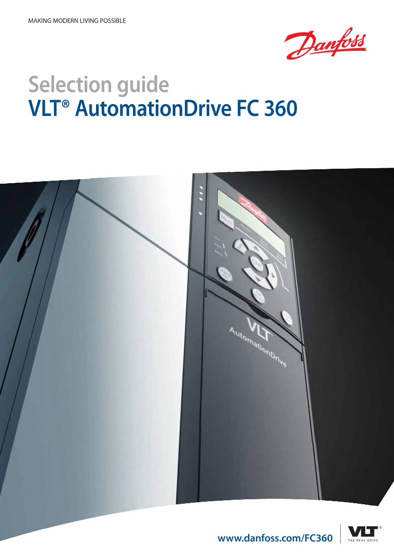
Selection guide VLT® AutomationDrive FC 360 - techtrends.ru · Danfoss developed and launched in...
16
www.danfoss.com/FC360 Selection guide VLT® AutomationDrive FC 360 MAKING MODERN LIVING POSSIBLE
Transcript of Selection guide VLT® AutomationDrive FC 360 - techtrends.ru · Danfoss developed and launched in...
www.danfoss.com/FC360
Selection guideVLT® AutomationDrive FC 360
MAKING MODERN LIVING POSSIBLE
2
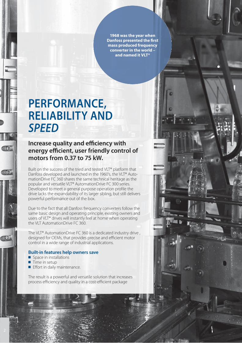
Increase quality and effi ciency with energy effi cient, user friendly control of motors from 0.37 to 75 kW.
Built on the success of the tried and tested VLT® platform that Danfoss developed and launched in the 1960’s, the VLT® Auto-mationDrive FC 360 shares the same technical heritage as the popular and versatile VLT® AutomationDrive FC 300 series. Developed to meet a general purpose operation profi le the drive lacks the expandability of its larger sibling, but still delivers powerful performance out of the box.
Due to the fact that all Danfoss frequency converters follow the same basic design and operating principle, existing owners and users of VLT® drives will instantly feel at home when operating the VLT AutomationDrive FC 360.
The VLT® AutomationDrive FC 360 is a dedicated industry drive , designed for OEMs, that provides precise and effi cient motor control in a wide range of industrial applications.
Built-in features help owners save■ Space in installations■ Time in setup ■ Eff ort in daily maintenance.
The result is a powerful and versatile solution that increases process effi ciency and quality in a cost-effi cient package
PERFORMANCE, RELIABILITY AND SPEED
1968 was the year when Danfoss presented the fi rst mass produced frequency
converter in the world – and named it VLT®
33
4
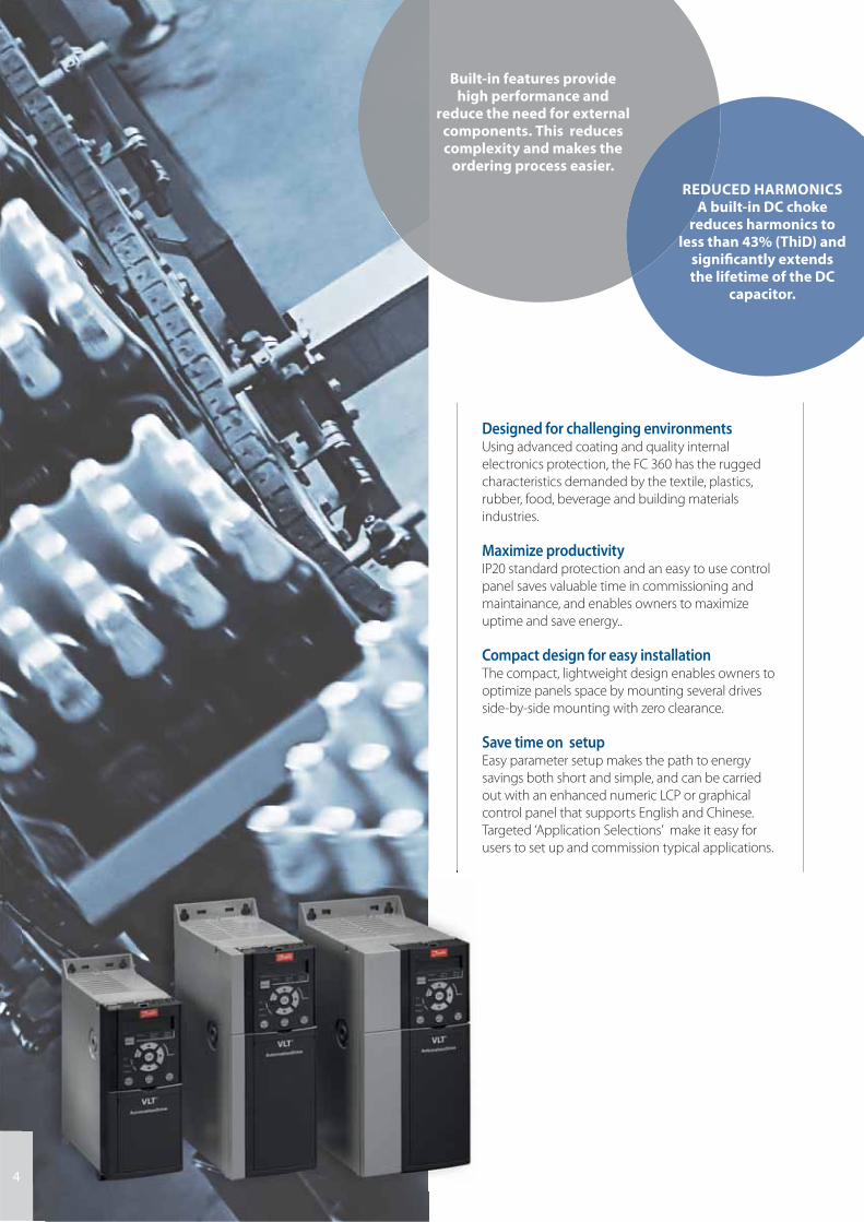
Designed for challenging environmentsUsing advanced coating and quality internal
electronics protection, the FC 360 has the rugged
characteristics demanded by the textile, plastics,
rubber, food, beverage and building materials
industries.
Maximize productivityIP20 standard protection and an easy to use control
panel saves valuable time in commissioning and
maintainance, and enables owners to maximize
uptime and save energy..
Compact design for easy installation The compact, lightweight design enables owners to
optimize panels space by mounting several drives
side-by-side mounting with zero clearance.
Save time on setupEasy parameter setup makes the path to energy
savings both short and simple, and can be carried
out with an enhanced numeric LCP or graphical
control panel that supports English and Chinese.
Targeted ‘Application Selections’ make it easy for
users to set up and commission typical applications.
Built-in features provide high performance and
reduce the need for external components. This reduces complexity and makes the
ordering process easier.
REDUCED HARMONICSA built-in DC choke
reduces harmonics to less than 43% (ThiD) and
signifi cantly extends the lifetime of the DC
capacitor.
5
HIGH RELIABILITY
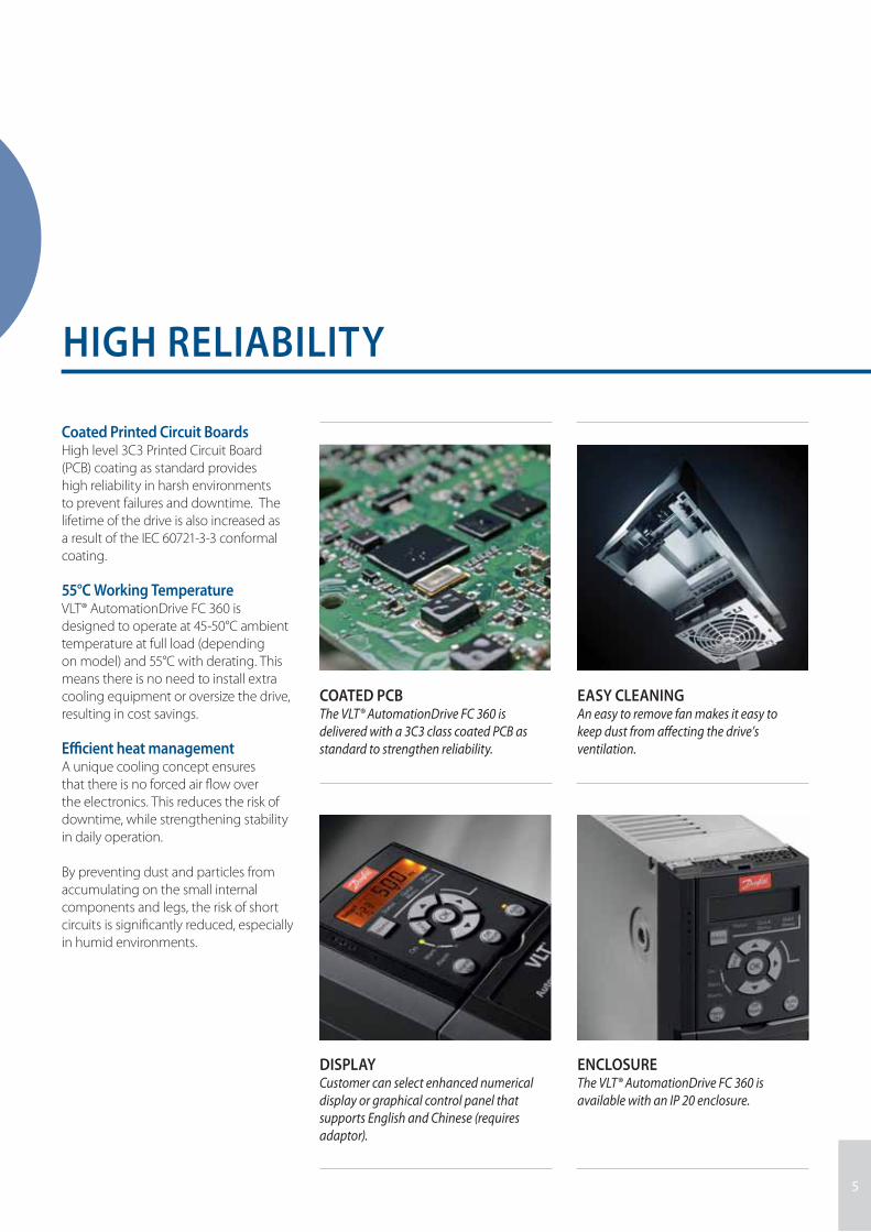
Coated Printed Circuit BoardsHigh level 3C3 Printed Circuit Board
(PCB) coating as standard provides
high reliability in harsh environments
to prevent failures and downtime. The
lifetime of the drive is also increased as
a result of the IEC 60721-3-3 conformal
coating.
55°C Working TemperatureVLT® AutomationDrive FC 360 is
designed to operate at 45-50°C ambient
temperature at full load (depending
on model) and 55°C with derating. This
means there is no need to install extra
cooling equipment or oversize the drive,
resulting in cost savings.
Effi cient heat managementA unique cooling concept ensures
that there is no forced air fl ow over
the electronics. This reduces the risk of
downtime, while strengthening stability
in daily operation.
By preventing dust and particles from
accumulating on the small internal
components and legs, the risk of short
circuits is signifi cantly reduced, especially
in humid environments.
COATED PCBThe VLT® AutomationDrive FC 360 is
delivered with a 3C3 class coated PCB as
standard to strengthen reliability.
DISPLAYCustomer can select enhanced numerical
display or graphical control panel that
supports English and Chinese (requires
adaptor).
EASY CLEANINGAn easy to remove fan makes it easy to
keep dust from aff ecting the drive’s
ventilation.
ENCLOSUREThe VLT® AutomationDrive FC 360 is
available with an IP 20 enclosure.
5
6
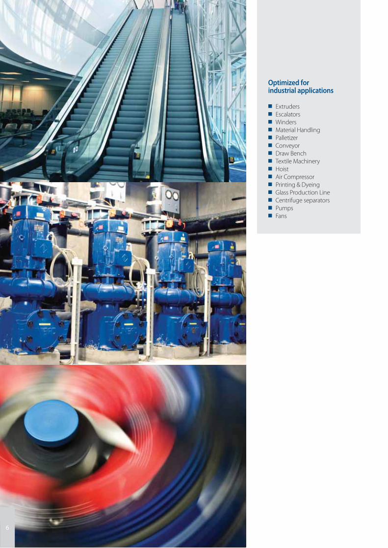
Optimized for industrial applications
■ Extruders■ Escalators■ Winders■ Material Handling■ Palletizer■ Conveyor■ Draw Bench■ Textile Machinery■ Hoist■ Air Compressor■ Printing & Dyeing■ Glass Production Line■ Centrifuge separators■ Pumps ■ Fans
77
PM motor controlThe FC 360 can provide highly effi cient
permanent magnet (PM) motor control
in open loop under VVC+ mode in
motors up to 22kW. Using Automatic
Motor Adaptation (AMA) the drive
adapts to the specifi c characteristics of
the permanent magnet motor.
Smart Logic ControlSmart Logic is a simple and clever way
to keep the drive, motor and application
working together. The smart logic
controller monitors a specifi c event, and
when it occurs, it triggers a predefi ned
action which is monitored for 20 steps,
before returning to step 1.
The Smart Logic Controller can monitor
any parameter that can be defi ned as
“true” or “false”, providing users with
signifi cant freedom to tailor the control
strategy to their specifi c needs. This
includes digital commands and logic
expressions, where sensor outputs can
infl uence operation using parameters
such as temperature, pressure, torque,
fl ow, time, load, frequency, voltage, and
others, combined with the operators
“>”, “<”, “=”, “and” and “or” as logical
statements.
Expand with control and feedback modulesFieldbus communication in VLT®
AutomationDrive FC 360 is integrated
in the control card. In addition, the
drive can be expanded with options
for additional control and encoder
feedback.
With the VLT® Encoder Input MCB 102
and VLT® Resolver Input MCB 103 the
VLT® AutomationDrive FC 360 can
receive encoder feedback from either a
motor or a process.
Time saving setup VLT® Motion Control Tool MCT 10The FC 360 can be confi gured and
monitored with Danfoss own VLT®
Motion Control Tool MCT 10 software.
This provides plant managers with
a comprehensive overview over the
system at any point in time and a high
level of fl exibility in confi guration and
monitoring.
MCT 10 is a windows based engineering
tool with a clearly structured interface
that provides an instant overview of all
the drives in a system of any size. The
software runs under Windows and
enables data exchange over a traditional
RS 485 interface or fi eldbus (PROFIBUS).
Parameter confi guration is possible both
online and offl ine, and the software can
be confi gured to link to the system’s
electrical diagrams or operating
manuals. This helps to reduce the risk of
incorrect confi guration while off ering
fast access to troubleshooting.
450 kg force at 0.6 Hz. The high torque performance of a 0.75 kW VLT® AutomationDrive FC 360 fully meets the demands for tensile testing at Samuya
Technocrates in India.
SPEED
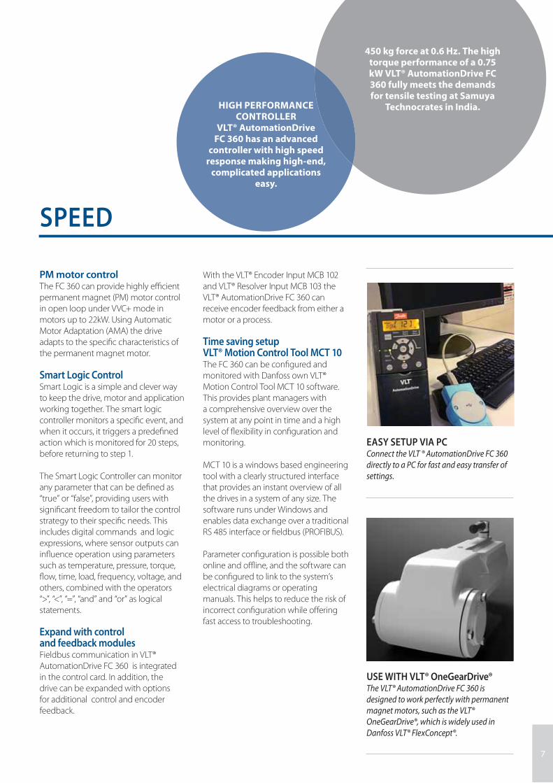
EASY SETUP VIA PCConnect the VLT ® AutomationDrive FC 360
directly to a PC for fast and easy transfer of
settings.
HIGH PERFORMANCE CONTROLLER
VLT® AutomationDrive FC 360 has an advanced
controller with high speed response making high-end,
complicated applications easy.
USE WITH VLT® OneGearDrive®The VLT® AutomationDrive FC 360 is
designed to work perfectly with permanent
magnet motors, such as the VLT®
OneGearDrive®, which is widely used in
Danfoss VLT® FlexConcept®.
88
Built-in Brake ChopperA built-in brake chopper up to 22kW
saves money and panel space.
Pulse Input as Speed ReferenceVLT® AutomationDrive FC 360 off ers the
capability to convert pulse input as a
speed reference, avoiding the need to
purchase an analog signal module for
PLC.
Center WinderFC 360 supports center winder
functionality, eliminating the need for
a special module in the programmable
logic control (PLC).
Built-in PID ControllerThe built in PID controller calculates an
‘error’ value as the diff erence between a
measured process variable and a desired
setpoint.
Built-in RFI FilterBuilt-in fi lters not only save space, but also
eliminate additional costs for fi tting, wiring,
and material. The most important
advantage is the perfect EMC conformance
and cabling of integrated fi lters.
The VLT® AutomationDrive FC 360 is designed to provide maximum uptime and reliability in a wide range of environments.
FEATURES DESIGNED TO MEET INDUSTRIAL NEEDS
4
5
6
2
3
1
DESIGNED FOR A WIDE RANGE OF POWER
SUPPLY CONDITIONSVLT® AutomationDrive FC 360 can operate at
-15% of supply voltage
See the interactive presentation and video at www.danfoss.com/fc360
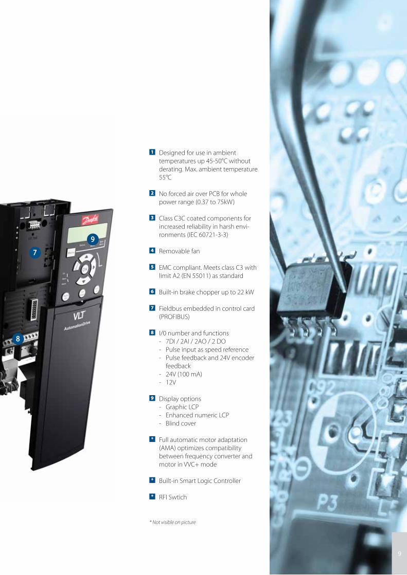
1 Designed for use in ambient
temperatures up 45-50°C without
derating. Max. ambient temperature
55°C
2 No forced air over PCB for whole
power range (0.37 to 75kW)
3 Class C3C coated components for
increased reliability in harsh envi-
ronments (IEC 60721-3-3)
4 Removable fan
5 EMC compliant. Meets class C3 with
limit A2 (EN 55011) as standard
6 Built-in brake chopper up to 22 kW
7 Fieldbus embedded in control card
(PROFIBUS)
8 I/0 number and functions
- 7DI / 2AI / 2AO / 2 DO
- Pulse input as speed reference
- Pulse feedback and 24V encoder
feedback
- 24V (100 mA)
- 12V
9 Display options
- Graphic LCP
- Enhanced numeric LCP
- Blind cover
* Full automatic motor adaptation
(AMA) optimizes compatibility
between frequency converter and
motor in VVC+ mode
* Built-in Smart Logic Controller
* RFI Swtich
* Not visible on picture
9
8
7
9
10
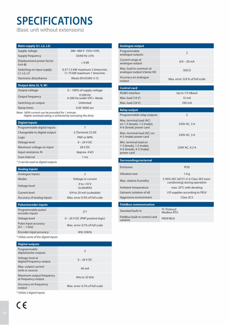
SPECIFICATIONS (Basic unit without extensions)
Main supply (L1, L2, L3)
Supply voltage 380–480 V -15%/+10%
Supply frequency 50/60 Hz ±5%
Displacement power factor(cos ф)
> 0.98
Switching on input supply L1, L2, L3
0.37-7.5 kW maximum 2 times/min.11-75 kW maximum 1 time/min.
Harmonic disturbance Meets EN 61000-3-12
Output data (U, V, W)
Output voltage 0 – 100% of supply voltage
Output frequency0-500 Hz
0-200 Hz under VVC+ Mode
Switching on output Unlimited
Ramp times 0.05-3600 sec
Note: 160% current can be provided for 1 minute. Higher overload rating is achieved by oversizing the drive.
Digital inputs
Programmable digital inputs 7
Changeable to digital output 2 (Terminal 27,29)
Logic PNP or NPN
Voltage level 0 – 24 V DC
Maximum voltage on input 28 V DC
Input resistance, Ri Approx. 4 kΩ
Scan interval 1 ms
* 2 can be used as digital outputs
Analog inputs
Analogue inputs 2
Modes Voltage or current
Voltage level0 to +10 V
(scaleable)
Current level 0/4 to 20 mA (scaleable)
Accuracy of analog inputs Max. error 0.5% of full scale
Pulse/encoder inputs
Programmable pulse/encoder inputs
2/1
Voltage level 0 – 24 V DC (PNP positive logic)
Pulse input accuracy (0.1 – 1 kHz)
Max. error: 0.1% of full scale
Encoder input accuracy 4Hz-32kHz
* Utilize some of the digital inputs
Digital outputs
Programmable digital/pulse outputs
2
Voltage level at digital/frequency output
0 – 24 V DC
Max. output current
(sink or source)40 mA
Maximum output frequency at frequency output
4Hz to 32 kHz
Accuracy on frequency output
Max. error: 0.1% of full scale
* Utilize 2 digital inputs
Analogue output
Programmable analogue outputs
2
Current range at analogue output
0/4 – 20 mA
Max. load to common at analogue output (clamp 30)
500 Ω
Accuracy on analogue output
Max. error: 0.8 % of full scale
Control card
RS485 interface Up to 115 kBaud
Max. load (10 V) 15 mA
Max. load (24 V) 100 mA
Relay output
Programmable relay outputs 2
Max. terminal load (AC) on 1-3 (break), 1-2 (make), 4-6 (break) power card
250V AC, 3 A
Max. terminal load (AC) on 4-5 (make) power card
250V AC, 3 A
Min. terminal load on 1-3 (break), 1-2 (make), 4-6 (break), 4-5 (make) power card
250V AC, 0.2 A
Surroundings/external
Enclosure IP20
Vibration test 1.0 g
Max. relative humidity5-95% (IEC 60721-3-3; Class 3K3 (non-
condensing) during operation
Ambient temperature max. 55°C with derating
Galvanic isolation of all I/O supplies according to PELV
Aggressive environment Class 3C3
Fieldbus communication
Standard built-inFC ProtocolModbus RTU
Fieldbus built-in control card variants
PROFIBUS

11
CONNECTION EXAMPLES The numbers represent the terminals on the drive
3 Phasepowerinput
Switch ModePower Supply
Motor
Analog Output
Interface
relay1
relay 2 2)
ON=Terminated
OFF=Open
Brakeresistor
13
0B
C4
38
.11
91 (L1)
92 (L2)93 (L3)
PE
50 (+10 V OUT)
53 (A IN)
54 (A IN)
55 (COM A IN)
0/4-20 mA
12 (+24V OUT)
31 (D IN)
18 (D IN)
20 (COM D IN)
10Vdc15mA 100mA
+ - + -
(U) 96(V) 97(W) 98(PE) 99
(A OUT) 45
(A OUT) 42
(P RS-485) 68
(N RS-485) 69
(COM RS-485) 61
(PNP) = Source
(NPN) = Sink
0V
5V
S801
0/4-20 mA
RS-485RS-485
03
3)
0/-10V DC -
+10V DC
0/4-20 mA0/-10V DC -
240V AC, 2A
24Vdc
02
01
05
06
04
240V AC, 2A24V (NPN)
0V (PNP)
0V (PNP)24V (NPN)
19 (D IN)
24V (NPN) 0V (PNP)27
24V
0V
(D IN/OUT)
0V (PNP)24V (NPN)
(D IN/OUT)
0V
24V29
24V (NPN) 0V (PNP)
0V (PNP)24V (NPN)
33 (D IN)
24V (NPN) 0V (PNP)
32 (D IN)
95
P 5-00
21 O
N
(-UDC) 88
(+UDC) 89
(BR) 81
The diagram shows the port terminals
of the VLT® AutomationDrive FC 360.
The numbers indicated refer to the
terminal numbers of the drives.
Users can set the mode of the analogue
inputs 53 and 54 by setting software
parameters.
The FC 360 features a RS485 interface
as standard. The RS485 terminations are
integrated in the drive (S801).
PROFIBUS DP can be specifi ed by
confi guring diff erent control cassette
when ordering.
To switch from NPN to PNP logic for the
digital signals, use parameter 5-00.
1 Built-in braking chopper available from 0.37 - 22 kW2 Relay 2 is 2 pole for J1-J3 and 3 pole for J4-J7. Relay 2 of
J4-J7 with terminal 4,5,6, same NO/NC logic as Relay 1.3 Dual DC choke in 30-75 kW4 Switch S801 (bus terminal) can be used to enable termi-
nation on the RS-485 port (terminals 68 and 69).5 Terminal 81 not available from 30 - 75kW
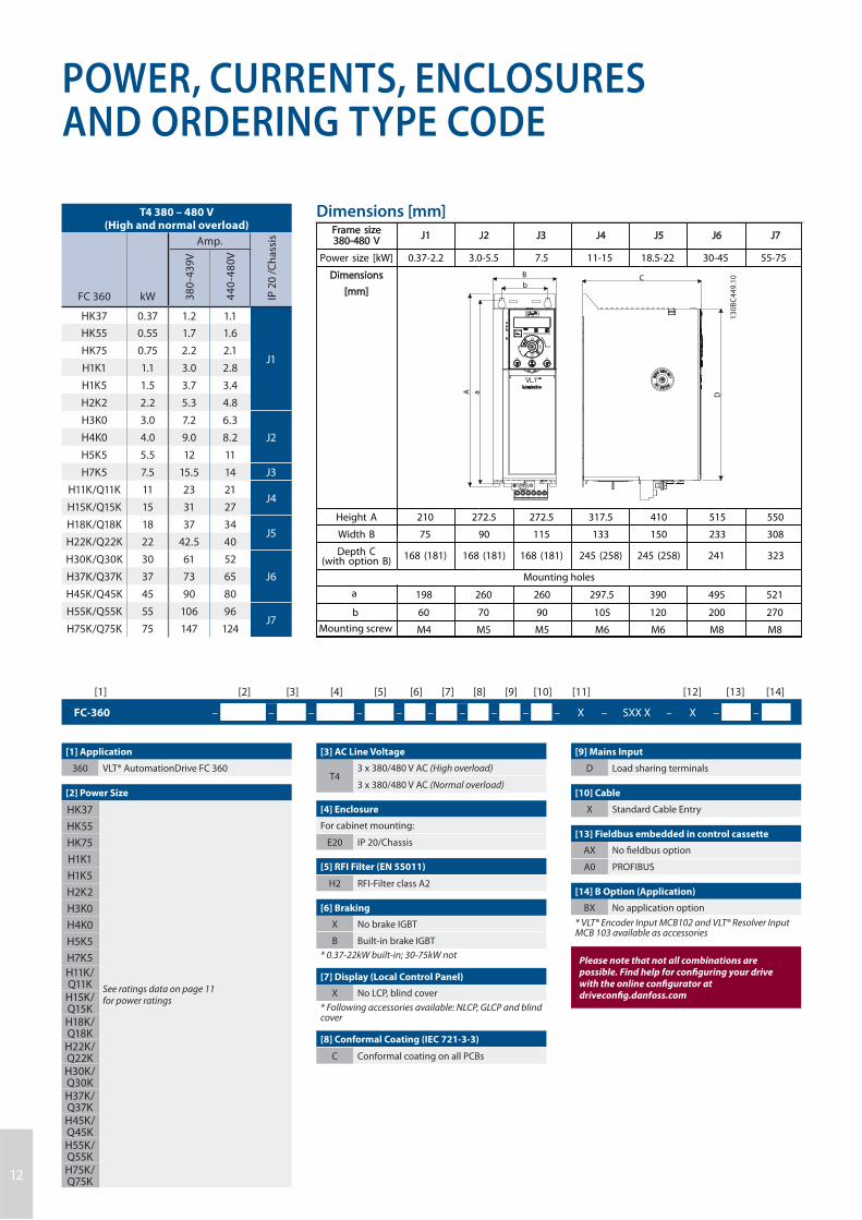
POWER, CURRENTS, ENCLOSURESAND ORDERING TYPE CODE
FC-360 – – – – – – – – – – X – SXX X – X – –
[1] [2] [3] [4] [5] [6] [7] [8] [9] [10] [11] [12] [13] [14]
[9] Mains Input
D Load sharing terminals
[10] Cable
X Standard Cable Entry
[13] Fieldbus embedded in control cassette
AX No fi eldbus option
A0 PROFIBUS
[14] B Option (Application)
BX No application option
* VLT® Encoder Input MCB102 and VLT® Resolver Input MCB 103 available as accessories
Please note that not all combinations are possible. Find help for confi guring your drive with the online confi gurator at driveconfi g.danfoss.com
[1] Application
360 VLT® AutomationDrive FC 360
[2] Power Size
HK37
See ratings data on page 11for power ratings
HK55
HK75
H1K1
H1K5
H2K2
H3K0
H4K0
H5K5
H7K5
H11K/Q11K
H15K/Q15KH18K/Q18KH22K/Q22KH30K/Q30KH37K/Q37KH45K/Q45KH55K/Q55KH75K/Q75K
Dimensions [mm]Frame size380-480 V
J1 J2 J3 J4 J5
Power size [kW] 0.37-2.2 3.0-5.5 7.5 11-15 18.5-22
J6
30-45
J7
55-75
Dimensions
[mm]
A a D
CB
b
13
0B
C4
49
.10
Height A 210 272.5 272.5 317.5 410
Width B 75 90 115 133 150
Depth C(with option B)
168 (181) 168 (181) 168 (181) 245 (258) 245 (258)
a
Mounting holes
198 260 260 297.5 390
b 60 70 90 105 120
Mounting screw M4 M5 M5 M6 M6
515
233
241
495
200
M8
550
308
323
521
270
M8
T4 380 – 480 V(High and normal overload)
FC 360 kW
Amp.
IP 2
0 /
Ch
ass
is
38
0-4
39
V
44
0-4
80
V
HK37 0.37 1.2 1.1
J1
HK55 0.55 1.7 1.6
HK75 0.75 2.2 2.1
H1K1 1.1 3.0 2.8
H1K5 1.5 3.7 3.4
H2K2 2.2 5.3 4.8
H3K0 3.0 7.2 6.3
J2H4K0 4.0 9.0 8.2
H5K5 5.5 12 11
H7K5 7.5 15.5 14 J3
H11K/Q11K 11 23 21J4
H15K/Q15K 15 31 27
H18K/Q18K 18 37 34J5
H22K/Q22K 22 42.5 40
H30K/Q30K 30 61 52
J6H37K/Q37K 37 73 65
H45K/Q45K 45 90 80
H55K/Q55K 55 106 96J7
H75K/Q75K 75 147 124
12
[3] AC Line Voltage
T43 x 380/480 V AC (High overload)
3 x 380/480 V AC (Normal overload)
[4] Enclosure
For cabinet mounting:
E20 IP 20/Chassis
[5] RFI Filter (EN 55011)
H2 RFI-Filter class A2
[6] Braking
X No brake IGBT
B Built-in brake IGBT
* 0.37-22kW built-in; 30-75kW not
[7] Display (Local Control Panel)
X No LCP, blind cover
* Following accessories available: NLCP, GLCP and blind cover
[8] Conformal Coating (IEC 721-3-3)
C Conformal coating on all PCBs
13
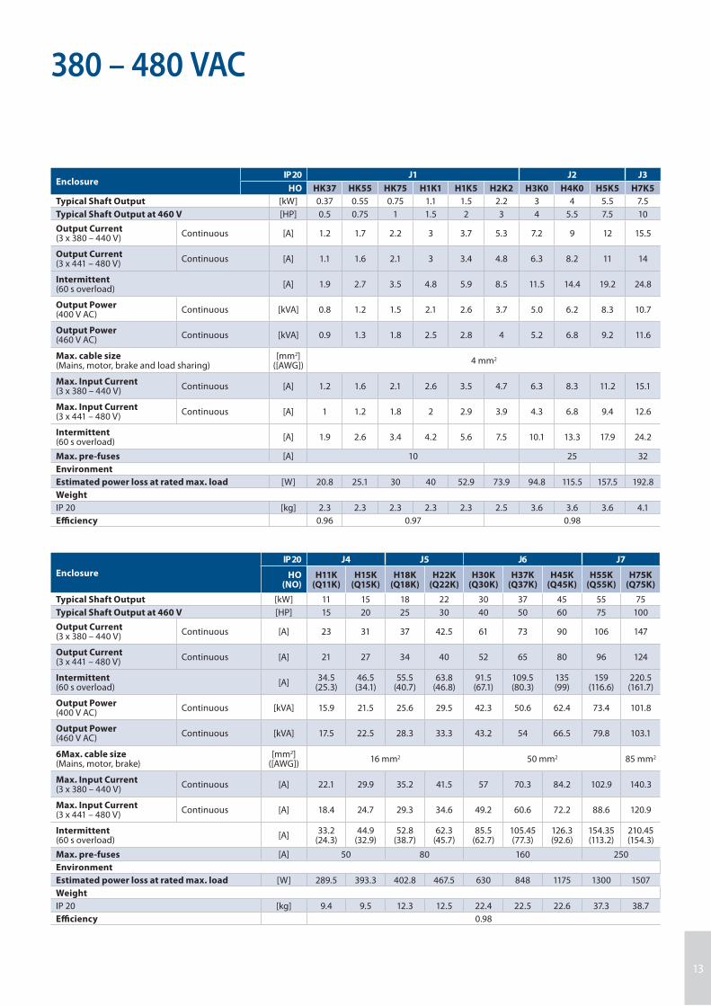
380 – 480 VAC
EnclosureIP 20 J1 J2 J3
HO HK37 HK55 HK75 H1K1 H1K5 H2K2 H3K0 H4K0 H5K5 H7K5
Typical Shaft Output [kW] 0.37 0.55 0.75 1.1 1.5 2.2 3 4 5.5 7.5
Typical Shaft Output at 460 V [HP] 0.5 0.75 1 1.5 2 3 4 5.5 7.5 10
Output Current(3 x 380 – 440 V)
Continuous [A] 1.2 1.7 2.2 3 3.7 5.3 7.2 9 12 15.5
Output Current(3 x 441 – 480 V)
Continuous [A] 1.1 1.6 2.1 3 3.4 4.8 6.3 8.2 11 14
Intermittent(60 s overload)
[A] 1.9 2.7 3.5 4.8 5.9 8.5 11.5 14.4 19.2 24.8
Output Power(400 V AC)
Continuous [kVA] 0.8 1.2 1.5 2.1 2.6 3.7 5.0 6.2 8.3 10.7
Output Power(460 V AC)
Continuous [kVA] 0.9 1.3 1.8 2.5 2.8 4 5.2 6.8 9.2 11.6
Max. cable size(Mains, motor, brake and load sharing)
[mm2]([AWG])
4 mm2
Max. Input Current(3 x 380 – 440 V)
Continuous [A] 1.2 1.6 2.1 2.6 3.5 4.7 6.3 8.3 11.2 15.1
Max. Input Current(3 x 441 – 480 V)
Continuous [A] 1 1.2 1.8 2 2.9 3.9 4.3 6.8 9.4 12.6
Intermittent(60 s overload)
[A] 1.9 2.6 3.4 4.2 5.6 7.5 10.1 13.3 17.9 24.2
Max. pre-fuses [A] 10 25 32
Environment
Estimated power loss at rated max. load [W] 20.8 25.1 30 40 52.9 73.9 94.8 115.5 157.5 192.8
Weight
IP 20 [kg] 2.3 2.3 2.3 2.3 2.3 2.5 3.6 3.6 3.6 4.1
Effi ciency 0.96 0.97 0.98
Enclosure
IP 20 J4 J5 J6 J7
HO (NO)
H11K(Q11K)
H15K(Q15K)
H18K(Q18K)
H22K(Q22K)
H30K(Q30K)
H37K(Q37K)
H45K(Q45K)
H55K(Q55K)
H75K(Q75K)
Typical Shaft Output [kW] 11 15 18 22 30 37 45 55 75
Typical Shaft Output at 460 V [HP] 15 20 25 30 40 50 60 75 100
Output Current(3 x 380 – 440 V)
Continuous [A] 23 31 37 42.5 61 73 90 106 147
Output Current(3 x 441 – 480 V)
Continuous [A] 21 27 34 40 52 65 80 96 124
Intermittent(60 s overload)
[A]34.5
(25.3)46.5(34.1)
55.5(40.7)
63.8(46.8)
91.5(67.1)
109.5(80.3)
135(99)
159(116.6)
220.5(161.7)
Output Power(400 V AC)
Continuous [kVA] 15.9 21.5 25.6 29.5 42.3 50.6 62.4 73.4 101.8
Output Power(460 V AC)
Continuous [kVA] 17.5 22.5 28.3 33.3 43.2 54 66.5 79.8 103.1
6Max. cable size(Mains, motor, brake)
[mm2]([AWG])
16 mm2 50 mm2 85 mm2
Max. Input Current(3 x 380 – 440 V)
Continuous [A] 22.1 29.9 35.2 41.5 57 70.3 84.2 102.9 140.3
Max. Input Current(3 x 441 – 480 V)
Continuous [A] 18.4 24.7 29.3 34.6 49.2 60.6 72.2 88.6 120.9
Intermittent(60 s overload)
[A]33.2
(24.3)44.9
(32.9)52.8
(38.7)62.3
(45.7)85.5
(62.7)105.45(77.3)
126.3(92.6)
154.35(113.2)
210.45(154.3)
Max. pre-fuses [A] 50 80 160 250
Environment
Estimated power loss at rated max. load [W] 289.5 393.3 402.8 467.5 630 848 1175 1300 1507
Weight
IP 20 [kg] 9.4 9.5 12.3 12.5 22.4 22.5 22.6 37.3 38.7
Effi ciency 0.98
14
OPTIONS AND ACCESSORIES
VLT® Encoder Input MCB 102
A universal option for connection
of encoder feedback from either a
motor or a process. Feedback for
asynchronous motors.
Encoder module supports:■ Incremental encoders■ SinCos encoders as Hyperface®■ Power supply for encoders■ RS422 interface■ Connection to all standard 5 V
incremental encoders
Ordering number:
132B0282
VLT® Resolver Input MCB 103
Supports resolver feedback for
asynchronous motors.
■ Primary Voltage:
2 – 8 Vrms■ Primary Frequency:
2.0 kHz – 15 kHz■ Primary current max:
50 mA rms■ Secondary input voltage:
4 Vrms
Ordering number:
132B0283
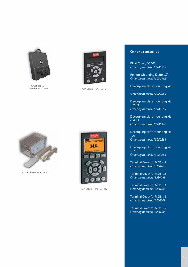
VLT® Control Panel LCP 21
Graphical LCP Adapter for FC 360
VLT® Control Panel LCP 102functions for FC 360
The numerical control panel fea-
tures an excellent user interface to
the drive.
■ Status messages■ Quick menu for easy
commissioning■ Parameter setting and
adjusting ■ Hand-operated start/stop func-
tion or Automatic mode select■ Reset function
Ordering number:
132B0254
The converter between FC 360 and
the graphical control panel of VLT®
AutomationDrive FC 300 series.
■ Supports Chinese and English
display (requires fi rmware 1.11 or
newer)
Ordering number:
132B0281
VLT® Brake Resistors MCE 101
Energy generated during braking
is absorbed by the resistors,
protecting electrical components
from heating up. Danfoss brake
resistors are optimized for the
FC-series.
General versions for horizontal and
vertical applications are also
available.
■ Enclosure protection as IP20
and up to IP65■ Built-in thermo switch■ Versions for vertical and hori-
zontal
mounting ■ UL-recognized – only types for
vertical mounting
PROFIBUS DP-V1
Operating the frequency converter
via a fi eldbus lets you reduce the
cost of your system, communi-
cate faster and more effi ciently,
and benefi t from an easier user
interface.
■ PROFIBUS DP-V1 gives you wide
compatibility, a high level of
availability, support for all major
PLC vendors, and compatibility
with future versions ■ Fast, effi cient communication,
transparent installation, advan-
ced diagnosis and parameteri-
sation and auto- confi guration
of process data via GSD-fi le■ A-cyclic parameterisation using
PROFIBUS DP-V1, PROFIdrive or
Danfoss FC profi le state machi-
nes, PROFIBUS DP-V1, Master
Class 1 and 2
■ English and Chinese display ■ Status messages■ Quick menu for easy
commissioning■ Parameter setting and explana-
tion of parameter function■ Adjusting of parameters■ Full parameter backup and copy
function■ Alarm logging■ Hand-operated start/stop, or
Automatic mode selection■ Reset function
15
VLT® Control Panel LCP 21
VLT® Control Panel LCP 102
Graphical LCP Adapter for FC 360
VLT® Brake Resistors MCE 101
Other accessories
Blind Cover, FC 360
Ordering number: 132B0262
Remote Mounting Kit for LCP
Ordering number: 132B0102
Decoupling plate mounting kit
- J1
Ordering number: 132B0258
Decoupling plate mounting kit
- J2, J3
Ordering number: 132B0259
Decoupling plate mounting kit
- J4, J5
Ordering number: 132B0260
Decoupling plate mounting kit
- J6
Ordering number: 132B0284
Decoupling plate mounting kit
- J7
Ordering number: 132B0285
Terminal Cover for MCB - J1
Ordering number: 132B0263
Terminal Cover for MCB - J2
Ordering number: 132B0265
Terminal Cover for MCB - J3
Ordering number: 132B0266
Terminal Cover for MCB - J4
Ordering number: 132B0267
Terminal Cover for MCB - J5
Ordering number: 132B0268

Environmentally responsible
VLT® products are manufactured
with respect for the safety and
well-being of people and the
environment.
All frequency converter factories
are certifi ed according to ISO 14001
and ISO 9001 standards.
All activities are planned and
performed taking into account
the individual employee, the work
environment and the external en-
vironment. Production takes place
with a minimum of noise, smoke or
other pollution and environmen-
tally safe disposal of the products
is pre-prepared.
UN Global Compact
Danfoss has signed the UN Global
Compact on social and environ-
mental responsibility and our
companies act responsibly towards
local societies.
Impact on energy savings
One year’s energy savings from our
annual production of VLT® drives
will save the energy equivalent
to the energy production from a
major power plant. Better process
control at the same time improves
product quality and reduces waste
and wear on equipment.
What VLT® is all aboutDanfoss VLT Drives is the world leader among dedicated drives providers – and still gaining market share.
Dedicated to drives
Dedication has been a key word since
1968, when Danfoss introduced the
world’s fi rst mass produced variable
speed drive for AC motors – and
named it VLT®.
Twenty fi ve hundred employees
develop, manufacture, sell and service
drives and soft starters in more than
one hundred countries, focused only
on drives and soft starters.
Intelligent and innovative
Developers at Danfoss VLT Drives
have fully adopted modular principles
in development as well as design, pro-
duction and confi guration.
Tomorrow’s features are developed in
parallel using dedicated technology
platforms. This allows the develop-
ment of all elements to take place in
parallel, at the same time reducing
time to market and ensuring that
customers always enjoy the benefi ts
of the latest features.
Rely on the experts
We take responsibility for every
element of our products. The fact that
we develop and produce our own
features, hardware, software, power
modules, printed circuit boards, and
accessories is your guarantee of
reliable products.
Local backup – globally
VLT® motor controllers are operating
in applications all over the world and
Danfoss VLT Drives’ experts located in
more than 100 countries are ready to
support our customers with applica-
tion advice and service wherever they
may be.
Danfoss VLT Drives experts don’t stop
until the customer’s drive challenges
are solved.
benefi ts
DKDD.PB.304.A3.02 VLT® is a trademark of Danfoss A/S PE-MMSC 2014.01
Danfoss VLT Drives, Ulsnaes 1, DK-6300 Graasten, Denmark, Tel. +45 74 88 22 22, Fax +45 74 65 25 80www.danfoss.com/drives, E-mail: [email protected]