CONNECTICUT DEPARTMENT OF · PDF fileconsistent guide to InRoads Design requirements of the...
44
October 2015 CONNECTICUT DEPARTMENT OF TRANSPORTATION AEC Applications – Division of Facilities & Transit CTDOT InRoads SS2 Survey for Designers Workshop
Transcript of CONNECTICUT DEPARTMENT OF · PDF fileconsistent guide to InRoads Design requirements of the...

0
October 2015
CONNECTICUT DEPARTMENT OF TRANSPORTATION
AEC Applications – Division of Facilities & Transit
CTDOT
InRoads SS2 Survey for
Designers Workshop

1
CTDOT InRoads SS2 Survey for Designers Workshop
CTDOT – AEC Applications
2800 Berlin Turnpike • Room 3213
Newington, CT 06131
Phone 860.594.3320 • Fax 860.594.3372
Thanks !
Thanks go to all that contributed to the creation of
this document, especially to Jeff Beckwith for his
survey expertise, assistance in the field and
classroom.
The support and help has been invaluable and is
appreciated beyond measures.
Gabriele Hallock
2
Table of Contents
PREFACE 3
SECTION 1 ORIENTATION TO INROADS SURVEY ................................... 5
1.1 INROADS FILE TYPES ......................................................................................... 5
1.2 RESOURCE FILE STORAGE LOCATION ....................................................................... 6
1.3 PROJECT DEFAULTS ........................................................................................... 6
1.4 START UP - LAB 1 ............................................................................................ 8
SECTION 2 ELECTRONIC SURVEY DATA ............................................... 17
2.1 IMPORTING SURVEY DATA - LAB 2 ....................................................................... 17
2.2 FIXING CODE ERRORS ...................................................................................... 21
2.2.1 Fieldbook Data Dialog Box ..................................................................... 21
2.2.2 Point Codes ......................................................................................... 22
2.2.3 Style Manager and Alpha/Numeric codes ................................................. 24
2.3 EDIT SURVEY DATA - LAB 3 .............................................................................. 25
SECTION 3 CREATE SURFACE ............................................................... 29
3.1 WRITING SURVEY DATA TO GRAPHICS - LAB 4 ........................................................ 29
3.2 SURVEY DATA TO SURFACE – LAB 5 ..................................................................... 30
SECTION 4 SURFACE EDITING ............................................................. 34
4.1 FIXING CROSSING BREAKLINES – LAB 6 ................................................................ 34
4.2 CHANGING SURFACE FEATURE PROPERTIES – LAB 7 .................................................. 37
4.3 VIEW SURFACE TOOLS – LAB 8 .......................................................................... 39

3
Preface
Overview
The goals of the CTDOT InRoads V8i Survey for Designers Workshop are:
To give the designer a working understanding of how survey information is gathered in the field
including shot placement, breakline and survey limits.
To improve communication between the Survey and Design units when placing a survey request.
To understand the InRoads workflow, as it relates to how points taken in the field become a DTM and
how the MicroStation survey file is created.
To gain a better understanding of the existing DTM including viewing triangles and contours.
The CTDOT InRoads V8i Survey for Designers Guide will identify standard resource files, configurations,
and CAD functions used in the creation survey data.
The material covered in this guide does not replace the need for other references and training regarding
InRoads software. Additional publications and training may be needed for further clarification of CAD
procedures and functions. The intent of this guide is not to prevent or limit individual initiatives and
engineering judgment. Rather, it is meant to document standard digital design procedures currently in
practice at CTDOT.
The information provided in this guide is subject to change as technology and experience warrant.
Therefore, this guide will be updated as major revisions in design software and CTDOT DDE policies
occur.
Distribution
This manual, in its entirety, may be freely copied and distributed for the purpose of providing a
consistent guide to InRoads Design requirements of the Connecticut Department of Transportation. This
manual is available on the web.
Trademarks
“MicroStation” and “InRoads”, are registered trademarks of Bentley Systems, Incorporated. Other trade
names, computer protocols, and file formats mentioned in this manual are the trademarks of their
respective owners. In no event will the appearance of any graphic, description of a graphic, picture,
screen display, or any other method of conveying meaning, be considered to impair the rights of the
respective owners.

4
Prerequisites:
The required prerequisites for installing and using InRoads V8i are listed below.
MicroStation V8i SS 2 Version 08.11.07.492 or higher,
MicroStation V8i SS 3 Version 08.11.09.397 or higher,
InRoads V8i SS2 Version 08.11.07.428 or higher,
This is not configured to work with OpenRoads (InRoads V8i SS 3)
Online Application Help
As mentioned earlier, this manual is not intended to be a sole source of information for the InRoads
user. InRoads software has extensive online help available through Help on the InRoads Menu Bar.
Additionally, when using the different InRoads dialog boxes, each box has a Help button. These buttons
link directly to information specific to the InRoads process being performed. It is generally expected
that new or even seasoned InRoads users will need to reference the online help regularly. The best
solution to a problem usually requires testing and selecting from multiple options. Practice and
experience using InRoads is the key to becoming a proficient InRoads user. Also, InRoads Help contains
a media library with video presentations and examples of standard workflows.
In addition, there is other outside InRoads learning resources for CTDOT users. CTDOT employees can
access the internet for help and training on the Bentley Learning Web site:
http://www.bentley.com/en-US/Training/, or call Bentley directly at 1-800-778-4277 only for
SELECTservices or all others call 1-800-BENTLEY. To access these learning resources from Bentley
Systems, Inc., CTDOT employees should contact AEC Applications to have a Bentley SELECT-ID issued to
them. However, Consultant Engineering firms need to purchase their own training subscriptions directly
through Bentley.
CTDOT AEC Applications has setup InRoads preferences and standardized CTDOT InRoads practices in an
effort make using InRoads as productive as possible. If you have questions regarding this manual or the
CTDOT InRoads preference files, please contact:
Elaine Richard Gabriele Hallock Samantha Scharpf
Phone: 860-594-3278 Phone: 860-594-3244 Phone: 860-594-2902

CTDOT INROADS SS2 SURVEY FOR DESIGNERS WORKSHOP
5
Section 1 Orientation to InRoads Survey
InRoads Survey provides a vehicle for data transfer and reduction from total stations, GPS, and other
raw data sources. It includes a complete set of tools for adjustments, data analysis and editing of raw
input data. Also included are tools for coordinate geometry and DTM display. InRoads Survey allows
you to save data in geometry and DTM file types for further usage by other applications within the
InRoads product group. InRoads Survey has resource files that have been configured with CTDOT
standards.
MicroStation is the platform application which allows InRoads data to be displayed. MicroStation and
InRoads applications both work together to provide users with CAD functions. For example, InRoads
uses MicroStation files to display CAD graphics for a DTM. This guide will outline the InRoads commands
that are available to view, display and present InRoads design data in CAD files.
1.1 InRoads File Types
The InRoads road design process uses several different file types. All InRoads data is stored in external
files. The CAD file is used to view a graphical representation of the design data, but the graphics files do
not store the InRoads Data. For example, if the graphics that represent the horizontal alignment are
deleted, the InRoads geometry file is not modified.
The following InRoads resource files have been configured for the V8i Environment:
Preference File (*.xin) - This file contains the control settings of all the dialog boxes within InRoads. The
settings for surface, geometry and survey tools have all been confined to one .xin file, replacing the
previous two .ini files, .fxp and .fwf files. This is the main source of standardization where all InRoads
design and graphical output are configured to meet CTDOT standards.
Template Library (*.itl) – This file contains a storage area for typical sections. A template is comprised of
a series of points and components that represent breakline features. These are processed later using
the Roadway Designer command. Roadway features that have been processed are then saved to the
design surface. CTDOT has two standard .itl files; one for roadway use and the other for airport taxiway
and runway uses.
Style Sheet (*.xsl) - All style sheets have been provided by Bentley and are located on the local hard
drive, in the Inroads directory under Civil/XML Data. The View XML Reports command allows users to
select an .xsl style sheet, which specifies the exact information to pull from the .xml file and how to
format it. To further clarify, the .xml file contains raw or computed data; the .xsl file specifies how to
format the data into a report.
Drafting Notes (*.dft) - This file is used to enhance the production of final drawings. Use the commands
across the design session to place intelligent annotation notes on features and geometry, in the plan,
profile, and cross section views, as well as at the intersection of two alignments.

CTDOT INROADS SS2 SURVEY FOR DESIGNERS WORKSHOP
6
Pay Items (*.mdb) - This file is used with Quantity Manager. Quantity formulas and CTDOT pay items
are stored in this Microsoft Access database.
Drainage Structures (*.dat) - This file is used with InRoads Storm and Sanitary. This file has been
configured with CTDOT standard drainage structure information, including sizes, shapes, materials, and
many other parameters.
Rainfall Table (*.idf) - This file is used with InRoads Storm and Sanitary. This file contains a table of
Rainfall/Time of Concentration data that conforms to CTDOT drainage standards.
The following InRoads files need to be created for the project design:
Projects (*.rwk) - This file contains directory and file information for loading and saving InRoads data
files. Once the project file is open, all of the specific project files are also opened.
Surfaces (*.dtm) - A Digital Terrain Model (DTM) file is a surface where existing ground and design
terrain surface models are stored.
Geometry Projects (*.alg) – This file contains coordinate geometry and alignment information for a
specific geometric project.
Survey Data (*.fwd) – This InRoads Survey Fieldbook data file is created by importing survey data from a
field data collector.
XML Data (*.xml) - The XML Reports command, available as an application add-in under Tools on the
pull down menu, generates XML data files. The XML files are not reports, but contain data that can be
formatted into reports by using the View XML Reports command. XML data files are ASCII files that are
not formatted as a report for direct viewing. A report is the output generated when users display data
from an XML file using the View XML Reports command.
1.2 Resource File Storage Location
The latest versions of all V8i resource files will be kept in the workspace under InRoads_V8i _RSC. The
newest V8 level structure resource files will be found in the folder V8_Environment.
1.3 Project Defaults
An organized work environment along with a standardized file management system provides a
consistent way to maintain digital design data. These measures decrease the chance that users will
create and/or work with incorrect InRoads files. File management also eliminates the creation of
multiple copies of the same file. Therefore, a standardized file management system greatly increases
productivity by ensuring the availability of correct InRoads files and eliminating duplicate files.
By setting up the project defaults and creating a project file, users can quickly load all files needed for
project design. Additionally, the project file helps coworkers load and analyze current design data. The
Project Defaults command is used to open resource files including the preferences file (.xin) and drafting

CTDOT INROADS SS2 SURVEY FOR DESIGNERS WORKSHOP
7
file. This command is also used to set up default directories for all file types that can be accessed
through the File/Open and File/Save As dialog boxes. These include Project (.rwk), Surface (.dtm),
Geometry (.alg) and Survey Data (.fwd). All other files, which are opened or saved throughout the
InRoads program, use the Project Default Directory setting. The project default file directories are stored
in the computer’s registry on the local hard drive.
The following two methods, automated method and conventional method, can be used for setting up
project defaults:
The automated method based on variables, only has one configuration name. Files are opened
and paths are driven by the project user’s selection when opening MicroStation. Users can set
a windows system environment variable to define a project working directory. Use Project
Defaults to set the variable name using the syntax, $(variable) or %variable%.
The conventional method allows each project to have its own Configuration Name based on
hard-coded paths. When a particular configuration is saved and users exit the dialog, that
configuration is remembered as the "Current" configuration. The next time InRoads is accessed
all the directory paths are set according to the last configuration used. If the project has been
changed, users will need to select the corresponding project configurations. This means a
configuration name will be needed for every project that the user is working on.

CTDOT INROADS SS2 SURVEY FOR DESIGNERS WORKSHOP
8
1.4 Start Up - Lab 1
A. Open Windows Explorer and Browse to your projects folder, example: X:\999_Student_HIS##.
Within your project folder create the folder SURVEY under the ‘Highways’ setting for this
workflow only.
B. Again in Windows Explorer and Browse to the CTDOT V8i workspace, copy the following files to
the SURVEY folder just created, example: X:\999_Student_HIS##\Highways\SURVEY\.
W:\Workspace\InRoads_V8i_RSC\V8_Environment\
CT_civil.XIN & CT_notes.dft
C. Double-Click on the Accounting icon located on your desktop.
CTDOT INROADS SS2 SURVEY FOR DESIGNERS WORKSHOP
9
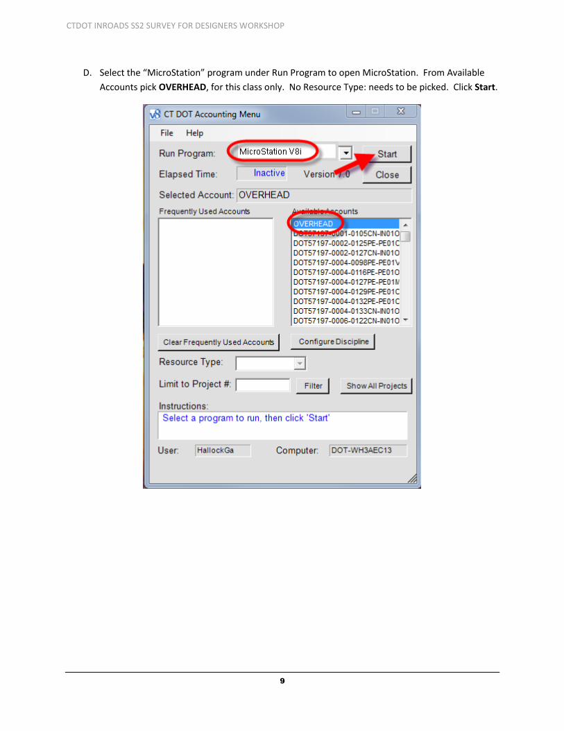
D. Select the “MicroStation” program under Run Program to open MicroStation. From Available
Accounts pick OVERHEAD, for this class only. No Resource Type: needs to be picked. Click Start.

CTDOT INROADS SS2 SURVEY FOR DESIGNERS WORKSHOP
10
E. In the File Open box, pick your interface and user preferences, then pick your project folder, all
training folders start with: 999_Student_HIS and a two digit number. The instructor will assign
you your project.
F. Go to the Survey folder and select the “New File” icon to create a new MicroStation file.

CTDOT INROADS SS2 SURVEY FOR DESIGNERS WORKSHOP
11
G. In the New dialog box select ‘Browse’ button and go to:
W:\CTDOT_Standards\Workspace\Standards\seed\SV_Design_Civil_3D_V8i.dgn and click
Open. Back in the ‘New’ dialog box type in a file name (SVY_HWY_DEMO_2015.dgn) and
select the Save button.
H. In the ‘File Open’ dialog box select the file that was just created (SVY_HWY_DEMO_2015.dgn)
and select the Open button. MicroStation will open.

CTDOT INROADS SS2 SURVEY FOR DESIGNERS WORKSHOP
12
I. From the MicroStation main menu select Element > Cells.
J. On the Cell Library Dialog box select File > Attach File… > Attach Cell Library. Browse to
W:\Workspace\InRoads_V8i_RSC\V8_Environment\cell\ and select SV_V8_LEVELS_40e.cel,
double-click or click Open. Close the cell library box. In MicroStation click on File > Save
Settings.
K. From the MicroStation main menu select Applications > InRoads Group > Activate InRoads
Suite and InRoads will open. Make sure ‘Survey’ is on the InRoads main menu.
CTDOT INROADS SS2 SURVEY FOR DESIGNERS WORKSHOP
13
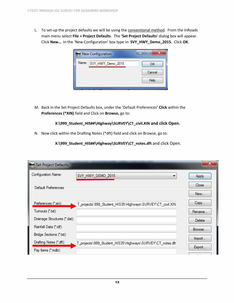
L. To set-up the project defaults we will be using the conventional method. From the InRoads
main menu select File > Project Defaults. The ‘Set Project Defaults’ dialog box will appear.
Click New… In the ‘New Configuration’ box type in: SVY_HWY_Demo_2015. Click OK.
M. Back in the Set Project Defaults box, under the ‘Default Preferences’ Click within the
Preferences (*XIN) field and Click on Browse, go to:
X:\999_Student_HIS##\Highway\SURVEY\CT_civil.XIN and click Open.
N. Now click within the Drafting Notes (*dft) field and click on Browse, go to:
X:\999_Student_HIS##\Highway\SURVEY\CT_notes.dft and click Open.
CTDOT INROADS SS2 SURVEY FOR DESIGNERS WORKSHOP
14
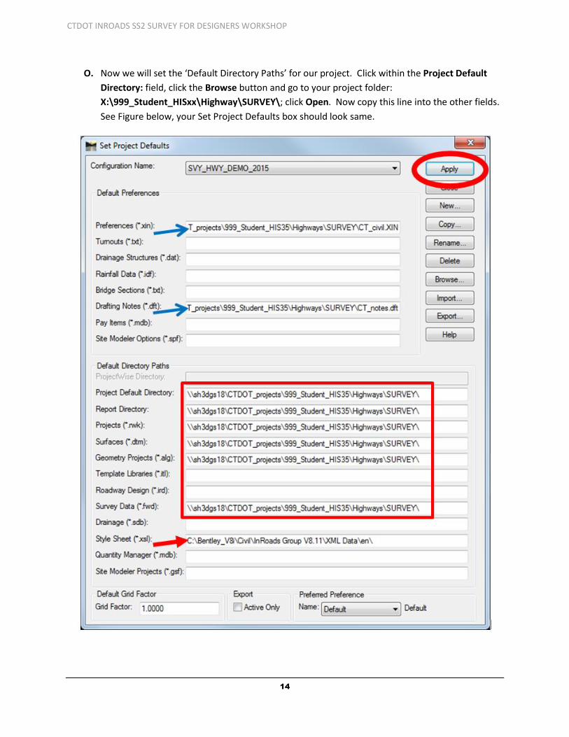
O. Now we will set the ‘Default Directory Paths’ for our project. Click within the Project Default
Directory: field, click the Browse button and go to your project folder:
X:\999_Student_HISxx\Highway\SURVEY\; click Open. Now copy this line into the other fields.
See Figure below, your Set Project Defaults box should look same.

CTDOT INROADS SS2 SURVEY FOR DESIGNERS WORKSHOP
15
P. For Style Sheet (*xsl): Browse to: C:\Bentley_V8i\Civil\InRoads Group V8.11\XML Data\en\,
click Open. All paths have been set. Now click on Apply and Close.
Q. From the InRoads Menu Bar “reselect” File > Project Defaults. At the bottom of the dialog box
select Survey for the Preferred Preference. Click Apply and Close. One more time open Project
Defaults to ensure Preferred Preferences are set to Survey.
R. Next from the InRoads Menu Bar select File > Project Options…. At the bottom select
Preferences… . The Preferences should already be set to Survey. Close both.

CTDOT INROADS SS2 SURVEY FOR DESIGNERS WORKSHOP
16
S. On the InRoads Interface right click next to Help and select Locks. One more time and select
Customize….
T. On the Customize dialog box toggle on Survey and View Survey Data and click Close. Dock the
InRoads Menus.
U. You completed Lab 1 - Start Up.

CTDOT INROADS SS2 SURVEY FOR DESIGNERS WORKSHOP
17
Section 2 Electronic Survey Data
2.1 Importing Survey Data - Lab 2
A. In InRoads Menu/Interface select File > New. , click on the Survey Data tab. In the name field
type in: SVY_HWY_Demo_2015. Click Apply and Close. In your InRoads interface click on the
Survey tab (bottom of interface) under Survey Data your file should show.
B. Now you have to save your survey data (*fwd) file. From the InRoads menu select File > Save
As, for Save as type: select Survey Data (*fwd) from the pull down menu. For Active: select
SVY_HWY_Demo_2015. This should populate the ‘File name:’ with:
SVY_HWY_Demo_2015.fwd. Click on Save, then Click Cancel to close the box.
CTDOT INROADS SS2 SURVEY FOR DESIGNERS WORKSHOP
18
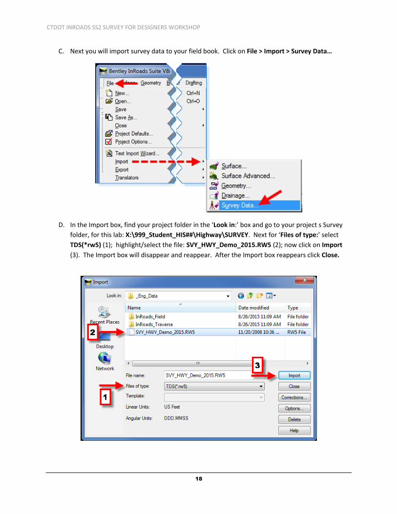
C. Next you will import survey data to your field book. Click on File > Import > Survey Data…
D. In the Import box, find your project folder in the ‘Look in:’ box and go to your project s Survey
folder, for this lab: X:\999_Student_HIS##\Highway\SURVEY. Next for ‘Files of type:’ select
TDS(*rw5) (1); highlight/select the file: SVY_HWY_Demo_2015.RW5 (2); now click on Import
(3). The Import box will disappear and reappear. After the Import box reappears click Close.
CTDOT INROADS SS2 SURVEY FOR DESIGNERS WORKSHOP
19
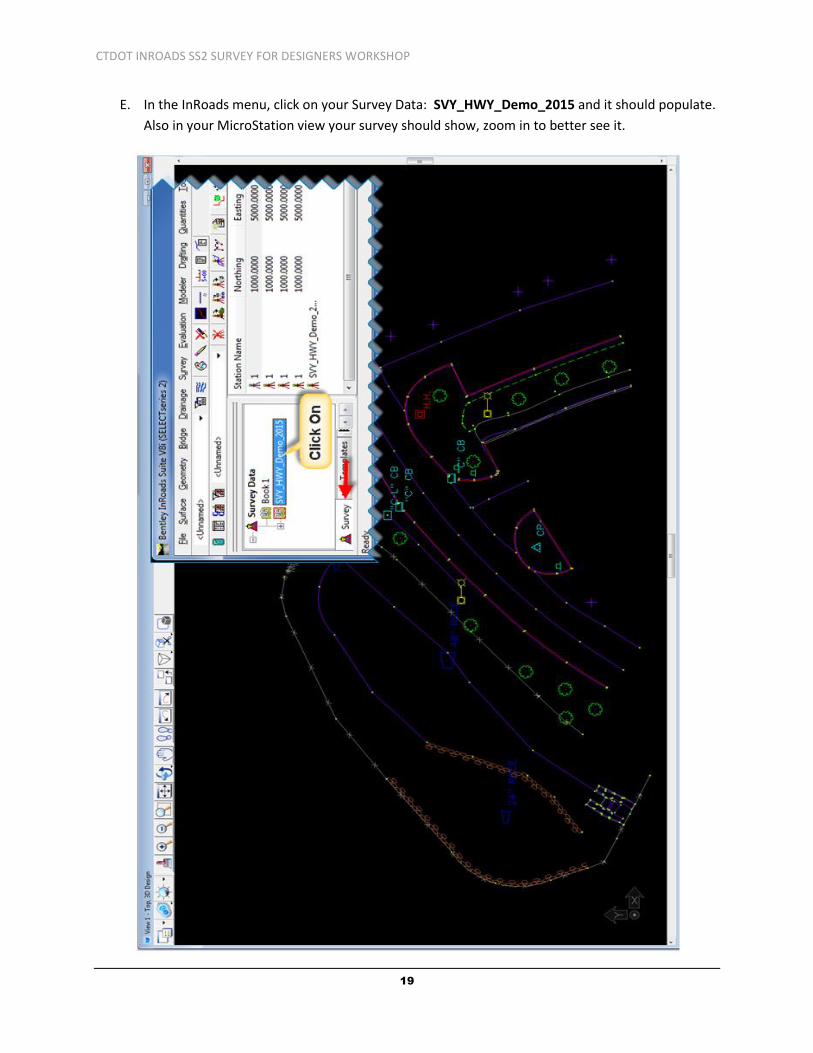
E. In the InRoads menu, click on your Survey Data: SVY_HWY_Demo_2015 and it should populate.
Also in your MicroStation view your survey should show, zoom in to better see it.

CTDOT INROADS SS2 SURVEY FOR DESIGNERS WORKSHOP
20
F. In the InRoads menu click on Tools > Survey Options… see figure below to set your Survey
Options box.

CTDOT INROADS SS2 SURVEY FOR DESIGNERS WORKSHOP
21
2.2 Fixing Code Errors
2.2.1 Fieldbook Data Dialog Box
This command lets you manage your field data. You can add, edit, delete, and find stations and
observations with the resizable Fieldbook Data dialog box. The Stations List contains occupied stations.
Selecting a station in the Stations List affects the Observations List. The Observations List contains
observations that were shot from the station points.
2.2.1.1 Stations List
Station Name - indicates the name of the occupied station. Stations are listed in the order in which
they were gathered in the field.
Northing - indicates the northing coordinate for each station.
Easting - indicates the easting coordinate for each station.
Elevation - indicates the elevation for each station.
Code - indicates the control code associated with each station.
Status indicates the relevant status code(s) for each station. The status codes are:
N - the point has Notes.
E - the point has been Edited.
F - the point is a keyed-in (Fixed) coordinate.
A - the point has Attributes.
V - at least one of the attributes has a Value.
I - an Inserted point.
C - an adjusted point.
Backsight Point - indicates the name of the backsight point for the selected station.
Backsight Direction - indicates the backsight direction from either a north or south azimuth
Instrument Height - indicates the instrument height for each station.
Notes - indicates notes for the selected station.
Attributes - indicates attributes for the selected station.

CTDOT INROADS SS2 SURVEY FOR DESIGNERS WORKSHOP
22
2.2.1.2 Observations List
Point Name indicates the name of the observation. When you open or import a survey data file, if a
fixed point is encountered that has the same name but different coordinates from a previously
encountered fixed point, the name of the second occurrence of the point is assigned a suffix of _1. The
suffix for each subsequent occurrence is incremented (_2, _3, and so on).
Northing - indicates the northing coordinate for each point.
Easting - indicates the easting coordinate for each point.
Elevation - indicates the elevation for each point.
Code - indicates the feature code(s) associated with each observation.
Status indicates the relevant status code(s) for each observation. The status codes are:
N - the point has Notes.
E - the point has been Edited.
F - the point is a keyed-in (Fixed) coordinate.
A - the point has Attributes.
V - at least one of the attributes has a Value.
I - an Inserted point.
C - an adjusted point.
Horizontal Observation - indicates the horizontal angle for each observed point.
Vertical Observation - indicates the vertical angle for each observed point.
Slope Distance - indicates the slope distance to each observed point.
Target Height - indicates the height of the prism above the observed point.
Notes - indicates notes for the selected observation.
Attributes - indicates attributes for the selected observation.
2.2.2 Point Codes
Each station or observation in the field book is assigned a point code. The point code consists of two
parts, an alpha/numeric code and a control code. By assigning an alpha/numeric code to a particular
station or observation, that point will be associated to one or more styles listed in the Style Manager (part
of the *.XIN file). By assigning a control code to a station or observation the construction of the
planimetric graphics (arcs and line segments) related to that point are determined. The process of
combining alpha/numeric codes with control codes is called point coding. Surveyors typically record point
codes in the field. In InRoads Survey, the point codes are activated from the Field Book Data dialog box by
right-clicking in the Stations list or the Observations list. The alpha/numeric codes and control codes
embedded in the field book data, act in concert to define the construction and symbology of planimetric
figures.

CTDOT INROADS SS2 SURVEY FOR DESIGNERS WORKSHOP
23
Control Codes describe geometric relationships among stations/observations in the field book. There are
15 control codes in InRoads Survey. Control Codes entered incorrectly in the field can to be edited and
fixed in the Field book.
Feature Description Control Code
Start Start a line ST
Close Close an object CL
Point of Curvature Start a curve PC
Point of Tangency End a curve PT
Exclude from Triangulation No DTM information DNC
Random Random point type in surfaces
generated by Survey Data to Survey
RND
Rectangle Form a rectangle based on two
shot points and a taped distance
RECT
Close Rectangle Close a rectangle based on
three shot points
CLSR
Nontangent Curve Use in conjunction with the PC
and PT to specify a nontangent
curve
NT
Join Point Join to a specified point number JPT
Join Nearest Code Join to the nearest previously
shot specified code
JNC
Distance Form a closed or open shape based on two shot points and
taped distances
DIST
Template Set up a template to run multiple linear features
TMPL
Cross Section Code Cross section code XS
Add to Adjustment Set Defines a foresight unknown point to be included with
adjustments data
ADJ
Extend Arc Closes an arc with another arc based on three field points,
creating a circle
EXTARC

CTDOT INROADS SS2 SURVEY FOR DESIGNERS WORKSHOP
24
2.2.3 Style Manager and Alpha/Numeric codes
The XIN file allows the user to create a feature usable by all areas of the product. Survey point data is
typically composed of two key aspects:
● Point location (Northing, Easting and Elevation)
● Physical characteristics of the object being recorded (Style Manager).
Each Survey Style has been predefined with CTDOT standard properties including:
● Named Symbology (color, line weight, line style, cell, text size and font)
● Codes - Alpha Codes and a Numeric Code.
● Custom Operations
A style is associated with a particular station or observation in the field book only when the appropriate
alpha/numeric code is used and the CTDOT XIN is loaded. A point entered in the field with the incorrect
code will not have the correct style or have no style associated to it when it is imported into the InRoads
Fieldbook.
The object's physical characteristics are modeled in the style. In other words, styles define symbology
(and more) for representing various real-world objects.
Example – Suppose a utility pole was shot at a certain point. The surveyor wishes to place a cell to
represent the utility pole in the CAD file at the point location. A style has been created that controls
which cell is placed at the point, the cell scale, rotation of the cell, level of the cell, and so on.
Example – Suppose a series of points representing an edge of pavement has been collected. A style has
been created that controls the color and line style of the graphics representing the edge of pavement.
The previous examples contain what are considered generic properties (cell, line style, level, color, and
so on). The surveyor often records more specific physical characteristics, and the style can model these
specific characteristics using attributes and custom operations, as in the following example.
Example – Suppose a manhole was shot at a certain point. In addition to a cell at the point, the surveyor
records an ID number of the manhole, as well as incoming and outgoing invert elevation. A style has
been made that controls the cell, and also recognizes three specific attributes (manhole ID number,
invert in, and invert out). Then using custom operations in InRoads Survey, data related to the three
attributes can be displayed for each manhole shot.
Associating stations/observations with styles is part of the process called point coding.

CTDOT INROADS SS2 SURVEY FOR DESIGNERS WORKSHOP
25
2.3 Edit Survey Data - Lab 3
A. Select Survey > View Survey Data and click on Names. In the MicroStation view window the
Point Names will now show. (Even when zoomed in they are very small.)
B. Select Survey > Find Point in View.
C. When the Find Point in View dialog appears, enter the point number 184 and radius: 2 (feet)
and click Apply. This will center the point to the screen and everything that is within a 2 ft.
radius.
CTDOT INROADS SS2 SURVEY FOR DESIGNERS WORKSHOP
26
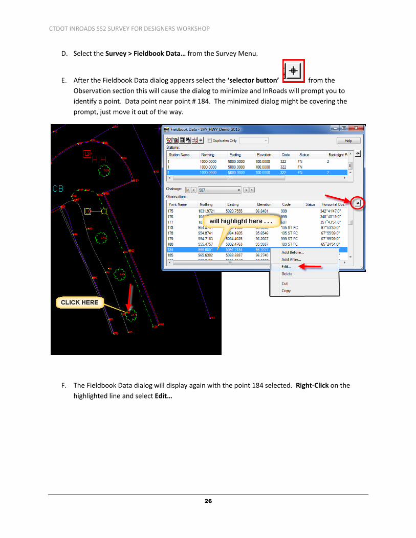
D. Select the Survey > Fieldbook Data… from the Survey Menu.
E. After the Fieldbook Data dialog appears select the ‘selector button’ from the
Observation section this will cause the dialog to minimize and InRoads will prompt you to
identify a point. Data point near point # 184. The minimized dialog might be covering the
prompt, just move it out of the way.
F. The Fieldbook Data dialog will display again with the point 184 selected. Right-Click on the
highlighted line and select Edit…

CTDOT INROADS SS2 SURVEY FOR DESIGNERS WORKSHOP
27
G. The Edit Observation dialog box will display. In the Code field after 507 type in ST PC and click
Apply. Click Close.
Note: Planimetric figures in InRoads Survey are graphical representations of objects with linear
characteristics as shown in this first edit. The Feature Style used for a row of shrubs is named SHRUB
ROW and has been created with a Numeric code 507. To begin a planimetric figure on a particular
station or observation, a code plus the designated start control code: 507 + ST PC must be specified.
Any subsequent station or observation containing the code 507 is included in the planimetric figure until
another ST code is encountered.
Features like catch basins and manholes are not typically part of a planimetric figure because they are
usually single shot points that have cells or attributes representation, so this point has no start code.

CTDOT INROADS SS2 SURVEY FOR DESIGNERS WORKSHOP
28
Now two more points will be edited.
H. In the Fieldbook Data dialog box select the selector button from the Observation section,
this will minimize the dialog once more and InRoads prompts you to identify a point. Data point
near point # 198.
I. Edit this point name and add PT NT after Code: 109.
J. Edit point name 199, add PT NT after Code: 109 999.
K. Edit point name 121, add PT after Code: 999.
L. Edit point name 122, add PT after Code: 104.
CTDOT INROADS SS2 SURVEY FOR DESIGNERS WORKSHOP
29
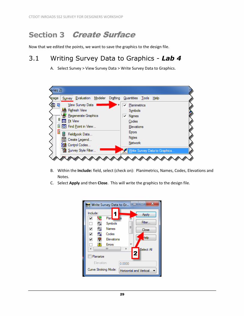
Section 3 Create Surface
Now that we edited the points, we want to save the graphics to the design file.
3.1 Writing Survey Data to Graphics - Lab 4
A. Select Survey > View Survey Data > Write Survey Data to Graphics.
B. Within the Include: field, select (check on): Planimetrics, Names, Codes, Elevations and
Notes.
C. Select Apply and then Close. This will write the graphics to the design file.

CTDOT INROADS SS2 SURVEY FOR DESIGNERS WORKSHOP
30
3.2 Survey Data to Surface – Lab 5
Now we will use our Fieldbook data (survey data) to create the existing surface (*.dtm).
A. From the InRoads main menu bar select Survey > Survey Data to Surface.
B. For Surface Name: input EXISTING. Toggle ON Always use: and select Style from pull-down.
Toggle OFF Triangulate Surface. Your Survey Data to Surface box should look as the figure
below. Click OK.

CTDOT INROADS SS2 SURVEY FOR DESIGNERS WORKSHOP
31
C. Select Surface > Triangulate Surface, the dialog box opens. For Surface: select EXISTING and
toggle ON Extended Data Checks. In the Results portion click on More… .
D. The Surface Properties dialog box opens. On the Main tab change the ‘Preference:’ to Survey.

CTDOT INROADS SS2 SURVEY FOR DESIGNERS WORKSHOP
32
E. On the Advanced tab change Cross Section and Profile Symbology to EXISTING.
F. Click Apply, after it processes click Close on the Surface Properties dialog box.
G. On the Triangulate Surface dialog box click Apply and Close. Close any error log that may open.
CTDOT INROADS SS2 SURVEY FOR DESIGNERS WORKSHOP
33
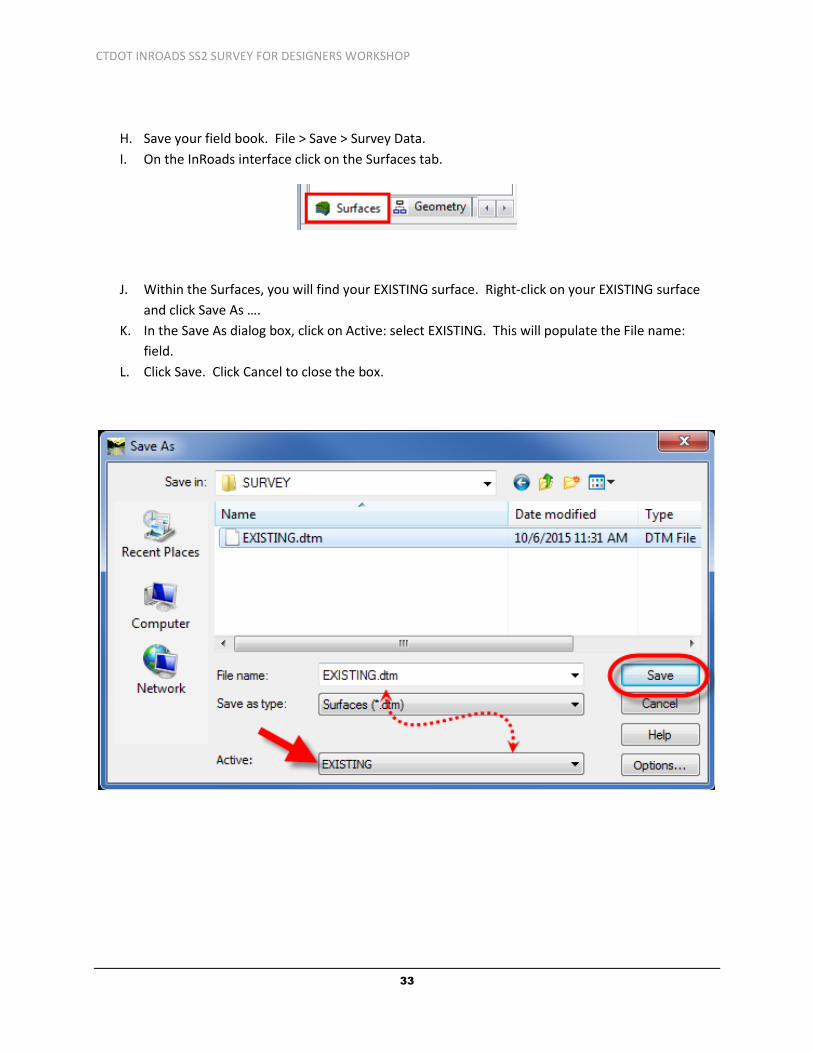
H. Save your field book. File > Save > Survey Data.
I. On the InRoads interface click on the Surfaces tab.
J. Within the Surfaces, you will find your EXISTING surface. Right-click on your EXISTING surface
and click Save As ….
K. In the Save As dialog box, click on Active: select EXISTING. This will populate the File name:
field.
L. Click Save. Click Cancel to close the box.

CTDOT INROADS SS2 SURVEY FOR DESIGNERS WORKSHOP
34
Section 4 Surface Editing
4.1 Fixing Crossing Breaklines – Lab 6
A. Now that we created an Existing surface we can close our field book. In the Survey tab, right-
click on the Fieldbook > Close. If a box to save changes pops up select Yes.
B. Select Surface > View Surface > Crossing Segments.
C. Select your EXISTING surface. Select Apply. Then Close.
CTDOT INROADS SS2 SURVEY FOR DESIGNERS WORKSHOP
35
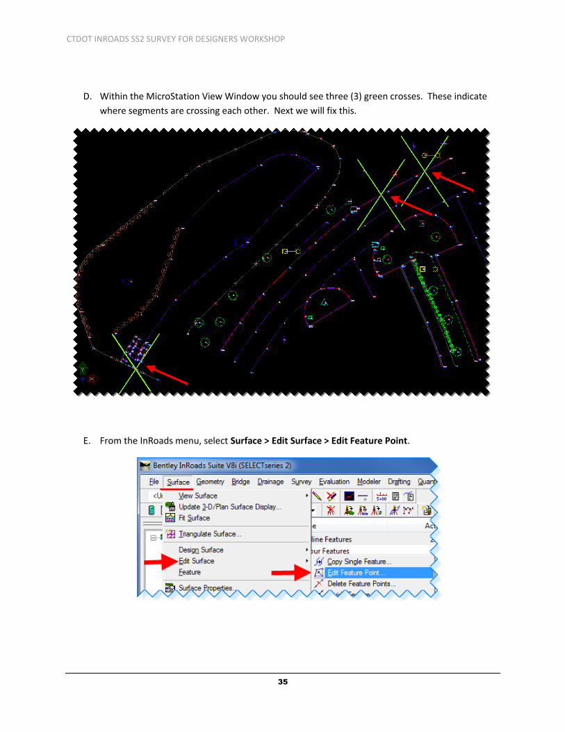
D. Within the MicroStation View Window you should see three (3) green crosses. These indicate
where segments are crossing each other. Next we will fix this.
E. From the InRoads menu, select Surface > Edit Surface > Edit Feature Point.

CTDOT INROADS SS2 SURVEY FOR DESIGNERS WORKSHOP
36
F. Within the Edit Feature Point dialog box. Select the pick button for Feature: .
G. In the MicroStation view zoom in to the green crosses. Select the purple breakline feature at
the bottom right of the spill way.
H. In the Edit Feature Point dialog box select the Target Button for the Northing and Easting
coordinates and modify breakline to be within gabion spillway. Datapoint (left click) to a point
within the gray spillway symbology. Select Apply. You have to repeat these steps for the
second point. Delete the purple line and the green crosses outside of the spillway using the
MicroStation delete tool.

CTDOT INROADS SS2 SURVEY FOR DESIGNERS WORKSHOP
37
I. Edit the other errors (green crosses). Target the purple breakline feature (points 116, 117, 120
& 121) and toggle left/right to select the first crossing point.
J. Target the North/East coordinate and modify the breakline to be behind the curbing, select
Apply. For each crossing vertices along the feature select and modify each point making sure to
click Apply after each point has been moved. Repeat until all points are behind the curb line.
K. Delete the breakline (purple line) that is now incorrect and the green crosses using MicroStation
delete tool.
L. In InRoads select Surface > Triangulate Surface and select Apply and Save your surface.
4.2 Changing Surface Feature Properties – Lab 7
A. Select Surface > Feature > Feature Properties.
B. In the Feature Properties dialog box click on the Selector button in the ‘Feature:’ area.

CTDOT INROADS SS2 SURVEY FOR DESIGNERS WORKSHOP
38
C. Pick the chain link fence surrounding the sedimentation control pond in the MicroStation view.
D. One of the chain link fence feature lines should highlight, select all chain link features (FECHLK)
within the Feature Properties box. Change the Triangulation Feature Type: from Random to
Breakline.
E. Select Apply and Close.
F. In InRoads select Surface > Triangulate Surface and select Apply and save your surface.

CTDOT INROADS SS2 SURVEY FOR DESIGNERS WORKSHOP
39
4.3 View Surface Tools – Lab 8
A. This lab shows InRoads users how to use the different viewing tools to display surface data
including the perimeter, triangles, contours and contour elevations.
B. Make sure the style lock is OFF. The style lock will allow the dialog box to appear.
C. On the InRoads Main menu bar click on Surface > View Surface > Perimeter.
D. In the View Perimeter dialog box for Surface: select EXISTING. Then click the Apply button.
Notice the line surrounding the parking lot; this is the limit of the existing surface.
E. On the InRoads main menu click on Surface > View Surface > Triangles.

CTDOT INROADS SS2 SURVEY FOR DESIGNERS WORKSHOP
40
F. In the View Triangles dialog box for Surface: select EXISTING. Then click Apply. Notice the
triangles appearing in the parking lot.
G. Looking at the triangles you can see some triangles need to be deleted. We will do this next,
but first save your EXISTING surface.

CTDOT INROADS SS2 SURVEY FOR DESIGNERS WORKSHOP
41
H. From the InRoads menu select Surface > Edit Surface > Delete Triangle… .
I. Select the EXISTING surface on the Delete Triangle dialog box. Click Apply. Now select the
triangles you want to delete. See the figure below as guide.

CTDOT INROADS SS2 SURVEY FOR DESIGNERS WORKSHOP
42
J. Cancel out of the delete Triangle command. Save your EXISTING surface.
K. Using MicroStation tools with graphic group on delete the display of the perimeter and
triangles.
L. Redisplay the perimeter and the triangles. View in MicroStation view. Then delete the triangles.
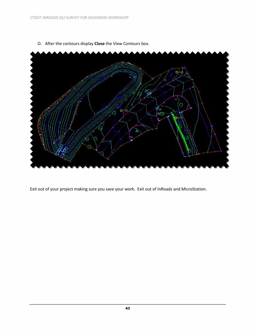
M. On the InRoads main menu bar click on Surface > View Surface > Contours.
N. The View Contours dialog box opens. Make sure Preferences… are set to Survey. On the Main
tab ensure Minors per Major: is set to 4. Click on Major Contours, Minor Contours and Major
Labels. Click Apply.
CTDOT INROADS SS2 SURVEY FOR DESIGNERS WORKSHOP
43
O. After the contours display Close the View Contours box.
Exit out of your project making sure you save your work. Exit out of InRoads and MicroStation.