InRoads User's Guide_rev1
16
Obtaining Cut & Fill Values for Site Development using InRoads User’s Guide February 2012_Rev1 JGC Philippines, Inc. Bentley Inroads v8i (v08.11.07.494)
-
Upload
anjobalucas -
Category
Documents
-
view
222 -
download
0
Transcript of InRoads User's Guide_rev1

7/25/2019 InRoads User's Guide_rev1
http://slidepdf.com/reader/full/inroads-users-guiderev1 1/16
Obtaining Cut & Fill Values forSite Development using
InRoadsUser’s Guide
February 2012_Rev1 JGC Philippines,Inc.
Bentley Inroads v8i (v08.11.07.494)
7/25/2019 InRoads User's Guide_rev1
http://slidepdf.com/reader/full/inroads-users-guiderev1 2/16
Obtaining Cut & Fill Values for Site Development Using InRoads User’s
Guide_rev1_’122
TABLE OF CONTENTS:
Introduction …….............................................................. 3
What is InRoads? ............................................................. 3
Preparation of InRoads’ reference Drawing ……………………………. 3
Getting Started with InRoads
Select CAD Platform ………………………………………………………… 4Opening InRoads ……………………………………………………………… 4
Parts of InRoads Window ………………………………………………… 5
Creating Preferences …………………………………………………….... 6Setting Preferences …………………………………………………………. 6
Creating a Surface
Existing SurfaceCreating existing surface …………………………………………. 7
Import Layers ………………………………………………………….. 8
View Imported Layers ……………………………………………… 9Saving Surface ………………………………………………………… 11
Design Surface
Create Design Surface ……………………………………………. 11
Import Layers …………………………………………………………. 12Viewing Imported Layers …………………………………………12
Save Surface …………………………………………………………….12
Computing Cut and Fill Volume for Surfaces ………………………….. 13
Surface Point Types ……………………………………………………………………15
How to Empty a Surface? ................................................... 15
Notes in Importing Layers for Design Surface ……………………….… 16

7/25/2019 InRoads User's Guide_rev1
http://slidepdf.com/reader/full/inroads-users-guiderev1 3/16
Obtaining Cut & Fill Values for Site Development Using InRoads User’s
Guide_rev1_’123
Introduction
Welcome to InRoads’. This User’s guide manual will help engineers to befamiliarized about InRoads software. This also teaches the steps requiredto obtain a cut and fill value for a surface.
What is InRoads?
InRoads software package is a design tool that allows the user to performcomplex geometry and surface modeling functions. It is a program thatuses various CAD packages such as Microstation and AutoCAD to displaygraphic information to the user.
The products that are part of the InRoads suite include InRoads, InRoadsbridge, InRoads Site, InRoads Storm and Sanitary, InRoads Survey andInRail. These products can run independently or simultaneously.
Preparation of InRoads Reference Drawing
InRoads requires a reference drawing in able to generate a surface.Wherein a reference drawing can be done at the same time we are usingInroads or by using a prepared drawing ready for import which will beused in this manual.
The following items are the required properties of a reference drawing:
a.) Reference drawing must be composed of a contour map and aplot plan.- We suggest having only one reference drawing to avoid
conflict in importing and viewing the surface generated byInRoads.
b.) Reference drawing must be in 1:1 scale since InRoads is inmeters.
c.) Reference drawing must be made of polylines only.- For contour lines made of spline. Please refer to spline to
polylines conversion placed at Civil Database.
d.) All items should have a unique layer.
e.) Contour lines must have no space and but must have breakpoints.
f.) Contour Elevation must be exact and in meters.g.) Areas must be set to desired elevations.

7/25/2019 InRoads User's Guide_rev1
http://slidepdf.com/reader/full/inroads-users-guiderev1 4/16
Obtaining Cut & Fill Values for Site Development Using InRoads User’s
Guide_rev1_’124
Example: from the figure, area 1 must have an elevation propertyof 100m.
h.) For areas with embankment, set boundary at most economicalelevation.
Getting Started with InRoads
Select CAD Platform
Open Program Bentley InRoads Group Select CAD Platform
This window will display the CAD Platforms installed in your computer.Choose the one compatible to your reference drawing.
This CAD platform will serve as the viewer while InRoads handles theengineering.
Opening InRoads
1. Open InRoads by clicking its shortcut icon.
You can also open InRoads throughAutoCAD by:
Tools Load ApplicationThen load: CivAcadXM.ARX
2. After opening, you have to see the CAD Platform and InRoadswindow.
AREA 1 @100m
AREA 2 @110m
AREA 3 @100m
7/25/2019 InRoads User's Guide_rev1
http://slidepdf.com/reader/full/inroads-users-guiderev1 5/16
Obtaining Cut & Fill Values for Site Development Using InRoads User’s
Guide_rev1_’125
3. Close the current CAD Drawing and open the prepared referencedrawing to use.
4. Lock or turn-off all layers at CAD Platform in able to protect yourreference drawing.
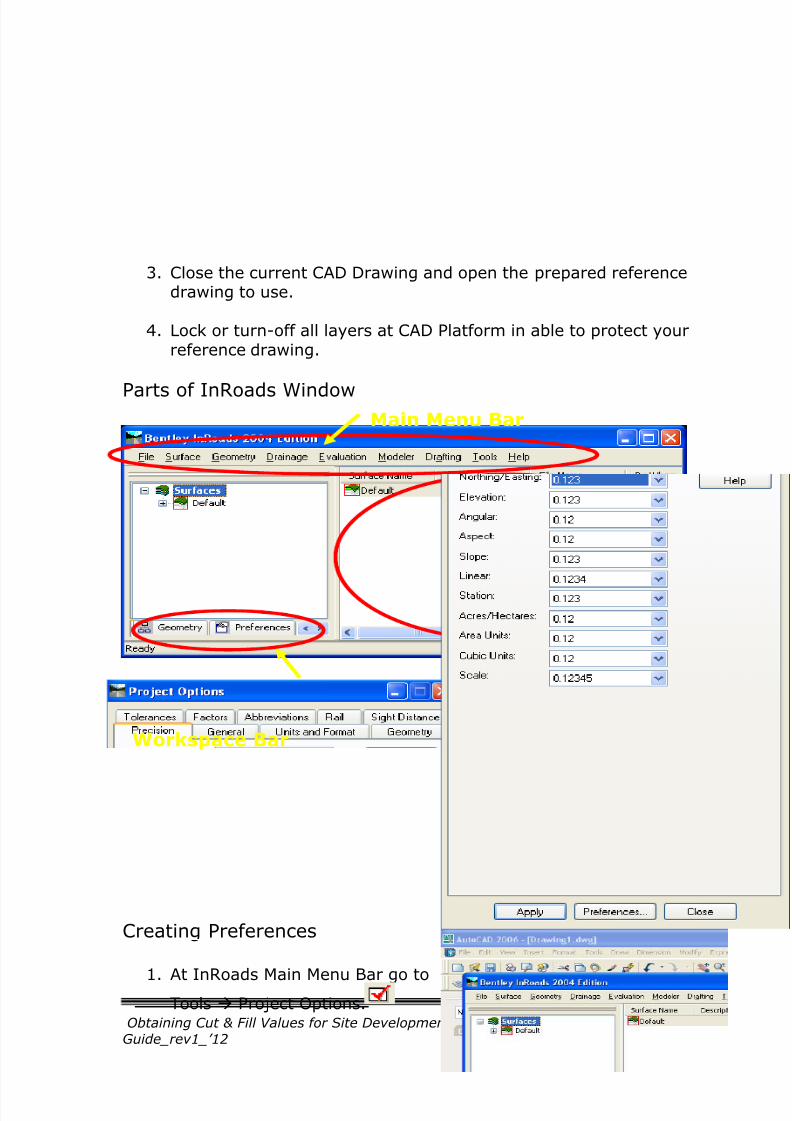
Parts of InRoads Window
Creating Preferences
1. At InRoads Main Menu Bar go toTools Project Options.
Main Menu Bar
Workspace Bar Feedback Pane
7/25/2019 InRoads User's Guide_rev1
http://slidepdf.com/reader/full/inroads-users-guiderev1 6/16
Obtaining Cut & Fill Values for Site Development Using InRoads User’s
Guide_rev1_’126
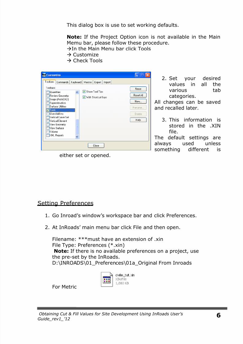
This dialog box is use to set working defaults.
Note: If the Project Option icon is not available in the MainMemu bar, please follow these procedure.In the Main Menu bar click Tools Customize
Check Tools
2. Set your desiredvalues in all thevarious tabcategories.
All changes can be savedand recalled later.
3. This information isstored in the .XINfile.
The default settings arealways used unlesssomething different is
either set or opened.
Setting Preferences
1. Go Inroad’s window’s workspace bar and click Preferences.
2. At InRoads’ main menu bar click File and then open.
Filename: ***must have an extension of .xinFile Type: Preferences (*.xin)Note: If there is no available preferences on a project, usethe pre-set by the InRoads.D:\INROADS\01_Preferences\01a_Original From Inroads
For Metric

7/25/2019 InRoads User's Guide_rev1
http://slidepdf.com/reader/full/inroads-users-guiderev1 7/16
Obtaining Cut & Fill Values for Site Development Using InRoads User’s
Guide_rev1_’127
For English
Creating a Surface
Existing Surface
It is a surface where you will import the reference drawing for contour. Itis the basis of your design surface.
1. Create Existing Surface
a. At InRoads’ workspace bar clickSurface.
b. At InRoads’ main menu bar click Filethen New.
a. At the dialog box, input thefollowing:
Type: ExistingName: “filename”Description: “__“Max. Length: 0Preference: “your filename forpre-set preferences”
b. Click Apply and close dialog box.
c. At InRoads left feedback pane, right click to your created surfaceand click Set Active.
A red box notes thatselected surface is currentlyactive.
Note: Always check if yoursurface is currently activebefore importing or saving inable to protect all data.

7/25/2019 InRoads User's Guide_rev1
http://slidepdf.com/reader/full/inroads-users-guiderev1 8/16
Obtaining Cut & Fill Values for Site Development Using InRoads User’s
Guide_rev1_’128
2. Import Layers
a. At InRoads main menu bar clickFile Import Surface
a. At the dialog box, inputthe following:
Load From: LayerLayer: AutoCAD’s layer name tobe importSeed name: ”__”Feature Style: DefaultPoint type: ***if layer to uploadis an exterior then point type isalso exterior.
b. Click Apply and closedialog box for importsurface.
b. At InRoads’ main menu bar click Surface triangulate Surface.
a. At the dialog box check if the indicated surface is your activesurface.
b. Check the Extended
Data Checks anduncheck LockTriangulation.
c. Max length should be0.00.
d. Click Apply then Close.

7/25/2019 InRoads User's Guide_rev1
http://slidepdf.com/reader/full/inroads-users-guiderev1 9/16
Obtaining Cut & Fill Values for Site Development Using InRoads User’s
Guide_rev1_’129
Triangulation is required to produce a surface. It corrects and reports onvarious problems that maybe in your surface. InRoads will also ‘autoresolve’ the crossing break lines when it triangulates.
c. At InRoads’ main menu bar clickSurface Utilities Generate
Inferred Break Lines.
a. At the Generate Inferred BreakLines dialogue box checktriangulate surface.
b. Click Apply then Close.
Point Types to upload in existing surface:
Exterior – it is the edge line or boundary of a certain area.Contour – for the contour lines or topographic mapInterior – it is an area inside the exterior not included for BQ.
(ex: lagoon,existing plant, or any area that will not bechange)
3. View Imported Layers
Perimeter
a. At InRoads main menu bar clickSurface View Surface Perimeter
a. At view perimeter dialoguebox, Surface must containthe active surface filename.
b. Click Preferences.
i. A dialogue bar forpreferences will appear.Highlight existing then load,save and close.

7/25/2019 InRoads User's Guide_rev1
http://slidepdf.com/reader/full/inroads-users-guiderev1 10/16
Obtaining Cut & Fill Values for Site Development Using InRoads User’s
Guide_rev1_’1210
c. At view perimeter dialogue box click apply then close.
Contour
a. At InRoads main menu bar clickSurface View Surface Contour
a. At the View Contoursdialogue box input thefollowing:
Surface: “filename”Interval: **depends uponthe contour drawing intervalMinors per major: **4 issuggested
b. Click Preferences.
i. At Preferences dialoguebox highlight thepreferences’ filenameyou created. Then ClickLoad, Save and Close.
c. At View Contours’ dialogue boxclick apply and close.
Interior (if any)
At InRoads main menu bar click Surface View Surface InteriorThe procedure will be same as the Import Layer.
After viewing imported layers checked if the surface generated byInRoads match up with reference drawing.
4. Saving a Surface

7/25/2019 InRoads User's Guide_rev1
http://slidepdf.com/reader/full/inroads-users-guiderev1 11/16
Obtaining Cut & Fill Values for Site Development Using InRoads User’s
Guide_rev1_’1211
a. Right click at the active surface then click Save.
b. Save dialogue box must contain the following:
Filename: “___”
Save as type: SurfaceActive: must be your surface to be saved
c. Note that surface has an extension name of .dtm.
d. Click Save then Close.
Design Surface
This is where to import the desiredarea for cut and fill.
1. Create Design Surface
a. At InRoads’ main menu bar clickFile New.
b. At the dialog box, input thefollowing:
Type: DesignName: “filename”Description: “__“Max. Length: 0.00Preference: “your filename forpre-set preferences”
c. Click Apply and close dialog box.
d. At InRoads left feedback pane, right click to your created surfaceand click Set Active.
7/25/2019 InRoads User's Guide_rev1
http://slidepdf.com/reader/full/inroads-users-guiderev1 12/16
Obtaining Cut & Fill Values for Site Development Using InRoads User’s
Guide_rev1_’1212
2. Import Layers
Procedure is the same for importing layers in existing surface.
Point Types to upload in design surface:
Exterior – it is the edge line or boundary of a certain area.Break line – it is an area inside the exterior desired for BQ.Interior – it is an area inside the exterior not included for BQ.
3. Viewing Imported Layers
PerimeterSame as the procedure for existing surface in viewing the
Perimeter.
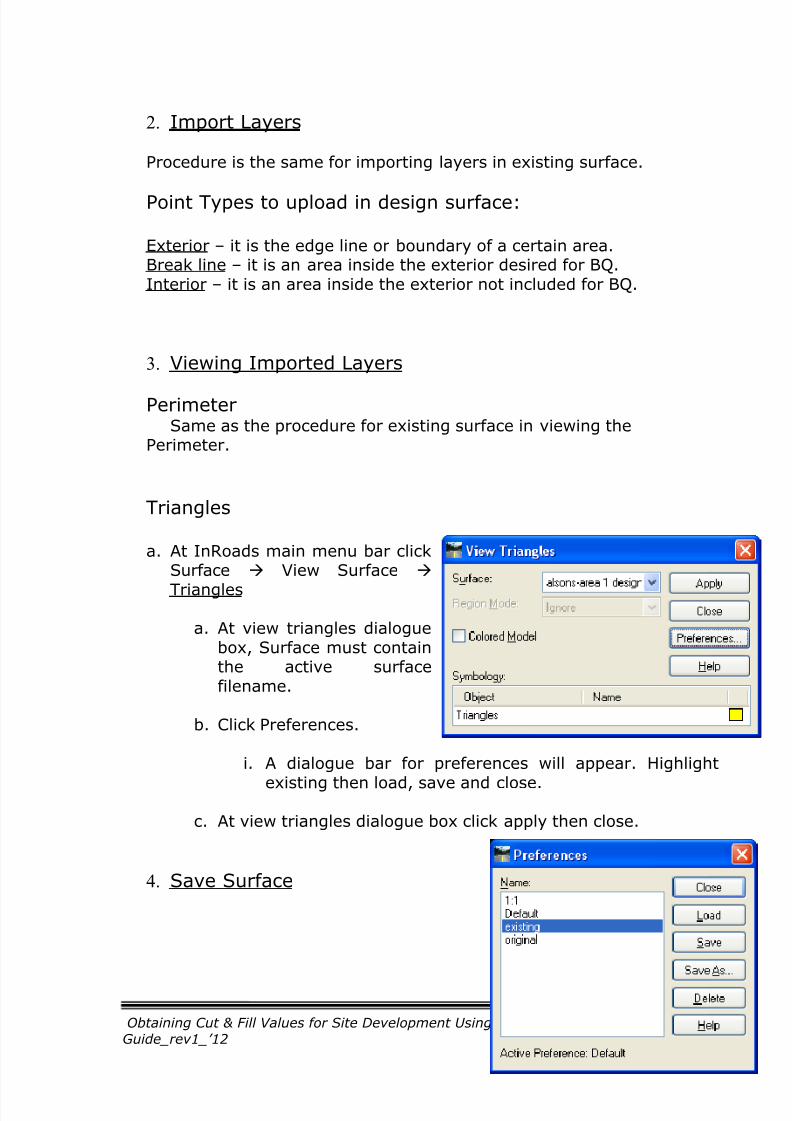
Triangles
a. At InRoads main menu bar clickSurface View Surface
Triangles
a. At view triangles dialoguebox, Surface must containthe active surfacefilename.
b. Click Preferences.
i. A dialogue bar for preferences will appear. Highlight
existing then load, save and close.
c. At view triangles dialogue box click apply then close.
4. Save Surface
7/25/2019 InRoads User's Guide_rev1
http://slidepdf.com/reader/full/inroads-users-guiderev1 13/16
Obtaining Cut & Fill Values for Site Development Using InRoads User’s
Guide_rev1_’1213
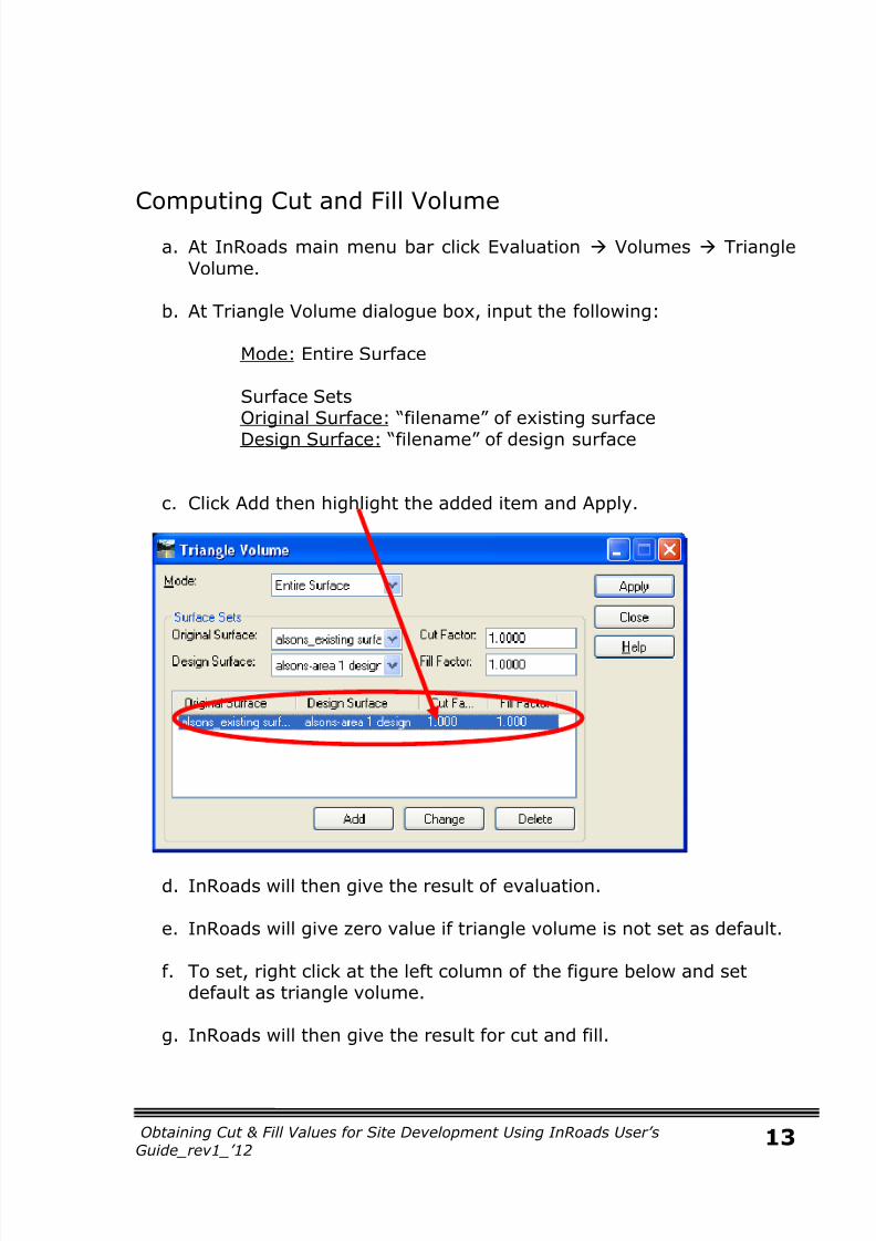
Computing Cut and Fill Volume
a. At InRoads main menu bar click Evaluation Volumes Triangle
Volume.
b. At Triangle Volume dialogue box, input the following:
Mode: Entire Surface
Surface SetsOriginal Surface: “filename” of existing surface
Design Surface: “filename” of design surface
c. Click Add then highlight the added item and Apply.
d. InRoads will then give the result of evaluation.
e. InRoads will give zero value if triangle volume is not set as default.
f. To set, right click at the left column of the figure below and setdefault as triangle volume.
g. InRoads will then give the result for cut and fill.

7/25/2019 InRoads User's Guide_rev1
http://slidepdf.com/reader/full/inroads-users-guiderev1 14/16
Obtaining Cut & Fill Values for Site Development Using InRoads User’s
Guide_rev1_’1214
h. Save the evaluation at Bentley InRoads Report Browser window
File Save
Surface Point types:
Random Points – singular points with x, y and z direction. Theyhave no relationship with other points.
Break line Points – are used in surface model where a linear
relationship exists along a path. Two or more points are required todefine a break line.
Interior Boundary Points – defines a void area. No computationoccurs inside these void areas. It must be a closed figure.
Exterior Boundary Point – are used to limit the outer extent of themodel. No computation occurs outside the exterior limit. Only 1exterior boundary can be defined per model.
Contour Points – is a graphic element in which all points are atsingle elevation.
How to Empty a Surface?
Right Click to the surface you wanted to empty.

7/25/2019 InRoads User's Guide_rev1
http://slidepdf.com/reader/full/inroads-users-guiderev1 15/16
Obtaining Cut & Fill Values for Site Development Using InRoads User’s
Guide_rev1_’1215
Right part of feedback pane must all be zero after emptying the surface.
Notes in Importing Layers for Design Surface
Exterior part is the black boundary. It is also the edge of PCWBS 5000area.
Example 1: to BQ Area 1
Import:
Boundary Exterior (exclude from triangulation)A1 Break lineA2 & A3 interior (optional input since A1 isimported as a break line.)
Inroads will then give a triangulation like this.
Example 2: to BQ PCWBS 5000
Import:Boundary Exterior
A1
EL+100
PCWBS 5000
A2
EL+105
A3
EL+110

7/25/2019 InRoads User's Guide_rev1
http://slidepdf.com/reader/full/inroads-users-guiderev1 16/16
Obtaining Cut & Fill Values for Site Development Using InRoads User’s
Guide_rev1_’1216
A1, A2 & A3 Break line
Inroads will then give a triangulation like this.
Note: In case there are spaces between each area (embankment), thevolume of these spaces will also be included in the computation if interioris not excluded from triangulation and vice versa.