AUXILIARY SAFETY SYSTEMS FOR TWO · PDF fileAbstract —Two wheelers are ... • Based...
12
© 2017 IJNRD | Volume 2, Issue 6 June 2017 | ISSN: 2456-4184 IJNRD1706019 International Journal of Novel Research and Development (www.ijnrd.org) 104 AUXILIARY SAFETY SYSTEMS FOR TWO WHEELERS 1 Mr. Nidal Ahmed Aftab Ahmed Pawne, 2 Mr. Gaurav Mohan Deo, 3 Mr. Armash Qutbuddin Farid, 4 Mr. Irfaan Ahmed Mohmed Yusuf Nishandar 1 Undergraduate, 2 Undergraduate, 3 Undergraduate, 4 Undergraduate 1 Mechanical Engineering Department, 1 Pillai College Of Engineering, Mumbai, India Abstract—Two wheelers are the most economical way of transport. Owning to this, there has been an increase in the number of two wheelers especially on Indian roads which has led to increasing number of accidents and fatality. Also lately there has been an increase in the pollution levels which has led to global warming. Keeping in mind the above problems, an integrated system was designed which will ensure the safety of riders as well as the environment. The integrated design consists of an automatic stand side retrieval, a smart helmet and a pollution sensing device. The components are integrated in such a way that the engine of the two-wheeler will start only when the helmet is worn. As soon as the helmet is worn and the engine is started, the side stand will be retrieved automatically. The pollution sensing device will start sensing the gases leaving the exhaust and as soon as the levels go above the limiting value of polluting gases, a warning beep will ring intimating that the two-wheeler is going above the pollution norms. Index Terms—Two wheeler safety systems, integrated system, automatic side stand retrieval, smart helmet, pollution sensing device, PUC device. I. INTRODUCTION In the modern world, automobile takes a great part in the development since it plays one of a major key in daily life. Two-wheelers play a very important role because it saves the time of the traveler by reaching the target place faster. Two-wheelers, the mode of transport most Indians use, continues to be the most vulnerable to accidents. The latest data released by the home ministry has revealed that 21% of the road death victims in 2015 in the country were riding two-wheelers. Estimates suggest that over 60% of the country's motor vehicles are two-wheelers. Many surveys across the country have shown that the motorcycles are more prone to accidents than other vehicles. Of the major traffic rule that people fail to follow is wearing a proper helmet. The alarming increase in mortality and morbidity owing to road traffic accidents has been a matter of great concern globally. The majority (77%) of the victims in India were in the age group 18-44 years. Accident rate among males (83%) was higher than that among females (17%). Five percent of the victims succumbed to injuries, of which 45 died on the spot. Geared vehicles (81%) were more commonly involved than those without gears. The highest number of accidents was seen during 6-10 pm. There are considerable morbidity and mortality due to two wheelers road traffic accidents. Among the fatalities, majority died on the spot. One of the most important safety rules to be followed while riding a motorcycle is wearing a helmet. And it is necessary for both the riders to wear helmets as in the case of an accident the driver, as well as the pillion is at equal risks of injury. Thus, there is no reason to think that only the driver needs protection. Of the 1,453 two-wheelers riders who died in road accidents in the city between January 1, 2013 and June 28, 2015, 1,434 were not wearing a helmet. The speed of the vehicle cannot be controlled in the situation of an accident. But safety factor can be increased to save lives. Wearing a helmet while participating in activities like bicycle riding or motorcycle riding can drastically lessen the chance of suffering a serious brain injury. All too often, people taking part in these activities are seriously injured because they chose not to wear a helmet. Motorcycle helmets and bike helmets lessen the impact of hard surfaces that hit the head during a bike or motorcycle accident. Helmets are designed to compress when struck, which decreases the severity of the impact by absorbing and dispersing force. Another simple thing people forget is uplifting of the side stand of the motorcycle while riding. 36% accidents in India are caused due to this mistake. The main reason for this is the rush that people make while riding a motorcycle. While the two-wheelers are concerned accidents occurs due to riding the vehicle at a high speed, ignoring to wear helmets, not maintaining the speed limit and forgetting to lift the side stand. These are the major source of accidents. Forgetting to lift the side stand causes large no. accidents in rural areas as well as partly in urban areas too. Because all the other source of accidents has preventive measure, but accidents due to side stand do not have a proper preventive measure. In order to reduce accidents due to carelessness in lifting the side-stand, many advance measures have been introduced like ECU; the modern ECU contains a 32 bit and 40 MHz processor. It will be fast as PC’s microprocessor. The ECU decides timing and functioning of the engine and its parts. This plays its role in the dashboard, this indicates the gear shifting, side stand, to wear helmet in digital display E.g., Hero Honda’s Karizma ZMR. But people ignore to listen those indicators and safety rules. So for safeguard, many mechanical projects have been found to retrieve the side stand automatically. Another important concern for two wheelers not only in India but all around the world is the Pollution caused by the bikes. Motorcycles emit substantial quantities of hydrocarbons (HCs), carbon monoxide (CO), and particulate matter (PM). These pollutants have significant adverse health effects and deteriorate environmental quality. The contribution to urban air pollution where these vehicles are in use has become an increasingly common phenomenon. This is especially noticed in densely populated areas that rely on motorcycles as an essential means of Transportation. Table 1: Statistics of Accidents S.NO DURING THE YEAR REASON FOR THE ACCIDENT %OF ACCIDENTS 1. 2002-2008 Forgetting to lift side-stand 36% 2. 2002-2008 Does not maintain speed limit 38%
Transcript of AUXILIARY SAFETY SYSTEMS FOR TWO · PDF fileAbstract —Two wheelers are ... • Based...
© 2017 IJNRD | Volume 2, Issue 6 June 2017 | ISSN: 2456-4184
IJNRD1706019 International Journal of Novel Research and Development (www.ijnrd.org) 104
AUXILIARY SAFETY SYSTEMS FOR TWO
WHEELERS 1Mr. Nidal Ahmed Aftab Ahmed Pawne,
2Mr. Gaurav Mohan Deo,
3Mr. Armash Qutbuddin Farid,
4Mr. Irfaan Ahmed Mohmed Yusuf Nishandar
1Undergraduate,
2Undergraduate,
3Undergraduate,
4Undergraduate
1Mechanical Engineering Department,
1Pillai College Of Engineering, Mumbai, India
Abstract—Two wheelers are the most economical way of transport. Owning to this, there has been an increase in the number of two
wheelers especially on Indian roads which has led to increasing number of accidents and fatality. Also lately there has been an increase
in the pollution levels which has led to global warming. Keeping in mind the above problems, an integrated system was designed which
will ensure the safety of riders as well as the environment. The integrated design consists of an automatic stand side retrieval, a smart
helmet and a pollution sensing device. The components are integrated in such a way that the engine of the two-wheeler will start only
when the helmet is worn. As soon as the helmet is worn and the engine is started, the side stand will be retrieved automatically. The
pollution sensing device will start sensing the gases leaving the exhaust and as soon as the levels go above the limiting value of polluting
gases, a warning beep will ring intimating that the two-wheeler is going above the pollution norms.
Index Terms—Two wheeler safety systems, integrated system, automatic side stand retrieval, smart helmet, pollution sensing device, PUC
device.
I. INTRODUCTION
In the modern world, automobile takes a great part in the development since it plays one of a major key in daily life. Two-wheelers
play a very important role because it saves the time of the traveler by reaching the target place faster. Two-wheelers, the mode of transport
most Indians use, continues to be the most vulnerable to accidents. The latest data released by the home ministry has revealed that 21% of
the road death victims in 2015 in the country were riding two-wheelers. Estimates suggest that over 60% of the country's motor vehicles are
two-wheelers. Many surveys across the country have shown that the motorcycles are more prone to accidents than other vehicles. Of the
major traffic rule that people fail to follow is wearing a proper helmet. The alarming increase in mortality and morbidity owing to road traffic
accidents has been a matter of great concern globally. The majority (77%) of the victims in India were in the age group 18-44 years.
Accident rate among males (83%) was higher than that among females (17%). Five percent of the victims succumbed to injuries, of which 45
died on the spot. Geared vehicles (81%) were more commonly involved than those without gears. The highest number of accidents was seen
during 6-10 pm. There are considerable morbidity and mortality due to two wheelers road traffic accidents. Among the fatalities, majority
died on the spot. One of the most important safety rules to be followed while riding a motorcycle is wearing a helmet. And it is necessary for
both the riders to wear helmets as in the case of an accident the driver, as well as the pillion is at equal risks of injury. Thus, there is no
reason to think that only the driver needs protection.
Of the 1,453 two-wheelers riders who died in road accidents in the city between January 1, 2013 and June 28, 2015, 1,434 were not
wearing a helmet. The speed of the vehicle cannot be controlled in the situation of an accident. But safety factor can be increased to save
lives. Wearing a helmet while participating in activities like bicycle riding or motorcycle riding can drastically lessen the chance of suffering
a serious brain injury. All too often, people taking part in these activities are seriously injured because they chose not to wear a helmet.
Motorcycle helmets and bike helmets lessen the impact of hard surfaces that hit the head during a bike or motorcycle accident. Helmets are
designed to compress when struck, which decreases the severity of the impact by absorbing and dispersing force.
Another simple thing people forget is uplifting of the side stand of the motorcycle while riding. 36% accidents in India are caused
due to this mistake. The main reason for this is the rush that people make while riding a motorcycle. While the two-wheelers are concerned
accidents occurs due to riding the vehicle at a high speed, ignoring to wear helmets, not maintaining the speed limit and forgetting to lift the
side stand. These are the major source of accidents. Forgetting to lift the side stand causes large no. accidents in rural areas as well as partly
in urban areas too. Because all the other source of accidents has preventive measure, but accidents due to side stand do not have a proper
preventive measure.
In order to reduce accidents due to carelessness in lifting the side-stand, many advance measures have been introduced like ECU;
the modern ECU contains a 32 bit and 40 MHz processor. It will be fast as PC’s microprocessor. The ECU decides timing and functioning
of the engine and its parts. This plays its role in the dashboard, this indicates the gear shifting, side stand, to wear helmet in digital display
E.g., Hero Honda’s Karizma ZMR. But people ignore to listen those indicators and safety rules. So for safeguard, many mechanical projects
have been found to retrieve the side stand automatically.
Another important concern for two wheelers not only in India but all around the world is the Pollution caused by the bikes.
Motorcycles emit substantial quantities of hydrocarbons (HCs), carbon monoxide (CO), and particulate matter (PM). These pollutants have
significant adverse health effects and deteriorate environmental quality. The contribution to urban air pollution where these vehicles are in
use has become an increasingly common phenomenon. This is especially noticed in densely populated areas that rely on motorcycles as an
essential means of Transportation.
Table 1: Statistics of Accidents
S.NO DURING THE YEAR REASON FOR THE ACCIDENT %OF ACCIDENTS
1. 2002-2008 Forgetting to lift side-stand 36%
2. 2002-2008 Does not maintain speed limit 38%

© 2017 IJNRD | Volume 2, Issue 6 June 2017 | ISSN: 2456-4184
IJNRD1706019 International Journal of Novel Research and Development (www.ijnrd.org) 105
Table 2. Indian Emission Standards (for 2 wheelers & 3 wheelers)
STANDARD DATE
Bharat Stage II 1st April 2005
Bharat Stage III 1st April 2010
Bharat Stage IV 1st April 2012
Bharat Stage V To be skipped
Bharat Stage VI April 2020 (proposed)
To address the serious pollution problems posed by two-wheel vehicles, a growing number of countries worldwide have
implemented, or are in the process of implementing, motor vehicle pollution control programs aimed at substantially reducing harmful
emissions from spark-ignited two-wheel vehicles. Bharat stage emission standards are emission standards instituted by the Government of
India to regulate the output of air pollutants from internal combustion engine equipment, including motor vehicles. Since October 2010,
Bharat Stage (BS) III norms have been enforced across the country. In 13 major cities, Bharat Stage IV emission norms have been in place
since April 2010. In 2016, the Indian government announced that the country would skip the BS-V norms altogether and adopt BS-VI norms
by 2020. In order to comply with the BSIV norms, 2 and 3 wheelers manufacturers will have to fit an evaporative emission control unit,
which should lower the amount of fuel that is evaporated when the motorcycle is parked.
II. LITERATURE REVIEW
The Bike Side stand unfolded ride lock link for two wheelers is the one of the lifesaving mechanism, which prevents the ride from
riding the bike in unreleased position (retracted position) of the side stand. This prevents the rider as well the vehicle to lose the center of
gravity by imbalance or surface hindrance due to retracted position of side stand and thereby saves the life of the rider. The side stand lock
link is cheap, rugged and easier to install without additional installations and fittings. The side stand lock link relates to the field of
automobiles industry, especially for two-wheelers vehicles using the side stand apart from the Main center stand provided therein for the
resting of the vehicle. The side stand lock link makes the contact with the gear lever thereby indicating the person handling the vehicle about
the unreleased side stand when the rider tries to apply the gear in unreleased state of the stand and prevents him from being endangered or to
have an unsafe ride of the motorcycle. The bike considered for the design of link is Bajaj Platina 100cc, 2008 model. The link is fabricated
with use of bending and punching processes. Presently many commercial two wheelers come with built in side stand locking systems with
indicator and alarm systems, but they are expensive and can’t be installed on the bikes that are in use (already on road) without the
provisions for fixing it. The developed side stand lock link can be fitted to any motorcycle with slight dimensional changes in the link. It is
simple in design, easy to fabricate and is low cost. (Sanjeev N. K., 2013).
The objective of this project is to make a system, which is embedded on helmet and bike. This system makes the rider to wear the
helmet for a safe ride. Different sensors are used for better safety of the motorcyclist. Bike can only be started when the motorcyclist wears
the helmet and does not consume alcohol. Whenever sensor detects alcohol, it switched ON an alarm and stops the bike. A speed sensor
provides another safety. When bike starts, it continuously checks the speed of the bike and warns the motorcyclist by giving a message and
switched ON an alarm, when speed crosses the limit, which is approximately 100Km/hour in our project. (Amit Varshnet, 2016).
Over recent past years, very strict legislation have been imposed on NOx, CO, particulate emissions, coming from vehicles or any
petrol engine. Hence in order to meet the environment legislation, it is highly desirable to reduce NOx percentage in the exhaust gases.
Predominantly, the petrol engine is used to drive two-wheelers, cars, some engines acting as prime mover, etc. As the use of two-wheelers is
increasing drastically, the emission is also increasing vigorously. So, technology like exhaust gas re-circulation must be emphasized to deal
with pollution problems. When the temperature inside the combustion chamber is high enough for long time, the nitrogen and oxygen
combine to form Nitrogen Oxides. Reduced cylinder temperature can be achieved by reducing the amount of oxygen in the cylinder. Exhaust
Gas Re-circulation technique will help to reduce the cylinder temperature. (Salunkhe Karan Vishwas, 2014)
III. METHODOLOGY
3.1 Side stand:
Problem Definition:
• 36% accidents occur due to rider forgetting to lift the side stand.
• Two types of preventive methods are i) Electronic side stand retrieval system ii) mechanical sprocket side stand retrieval system
• While the two-wheelers is concerned accidents occurs due to riding the vehicle in high speed, ignores to use helmets, does not
maintains the speed limit and forgets to lift the side stand while riding the vehicles.
Methodology:
• Based on the working principle of two-wheelers “sprocket-side stand retrieve system” is designed because this system works by
getting power from chain drive.
• Components used i) Axle ii) Sprocket Pinion iii) Lifting lever pushing lever
3.2 Smart Helmet:
Problem Definition:
• For the past 20 years it has been clearly noticed that the 2-wheelers road accidents ultimately result to death or severe injuries
mainly due to the absence of HELMET
• Wearing a helmet can reduce the impact of an accident and may also save a life
• Considering all the adversities and cause of accidents, this project has been made specially made to avoid it
Methodology:
• Adding four new features, we have a helmet buckle in sensor FSR (Force Sensing Resistor) for sensing the rider’s head
• Unless and until the helmet is buckled, the vehicle would not start
• A force-sensitive resistor has a variable resistance as a function of applied pressure
3. 2002-2008 Does not obey traffic rules 22%
4. 2002-2008 Other problems 04%
© 2017 IJNRD | Volume 2, Issue 6 June 2017 | ISSN: 2456-4184
IJNRD1706019 International Journal of Novel Research and Development (www.ijnrd.org) 106
• Force Sensing Resister is placed at inside the helmet where the actual human touch is sensed. It determines by helmet unit that
whether helmet is worn or not.
3.3 PUC sensor:
Problem Definition:
Pollution occurs when pollutants contaminate the natural surroundings; which brings about changes that affect our normal lifestyles
adversely.
Vehicle pollution (also transport pollution, motor pollution) is the introduction of harmful material into the environment by motor
vehicles. These materials, known as pollutants, have several bad effects on human health and the ecosystem. Examples of such
pollutants include Carbon monoxide, Hydrogen, Nitrogen Oxide, particulate matter, Ammonia and Sulphur Dioxide.
Methodology:
1. Motorcycles and scooters do not have exhaust air systems, which results in higher pollution compared to four-wheelers
2. By keeping in mind importance of pollution in world our team came up with an idea of emission check KIT in bike it self
3. For detection purpose we using MQ7 SENSOR
4. The MQ series of gas sensors use a small heater inside with an electro-chemical sensor. They are sensitive for a range of gasses and
are used indoors at room temperature.
IV. FABRICATION
4.1 Side Stand Retrieval system
The whole construction of this system is simple and efficient. Each and every component has its own property and responsibility. The power
obtained from the chain drive is transmitted to the appropriate component without power loss. The systematic design of system is made in
order to consume only very low amount of power initially for few seconds to retrieve the stand. Then the power consumption does not occur
after retrieving the stand. Construction of the side stand retrieval system consists of four major components. They are
Axle
Lifting lever
Pushing lever
Sprocket pinion
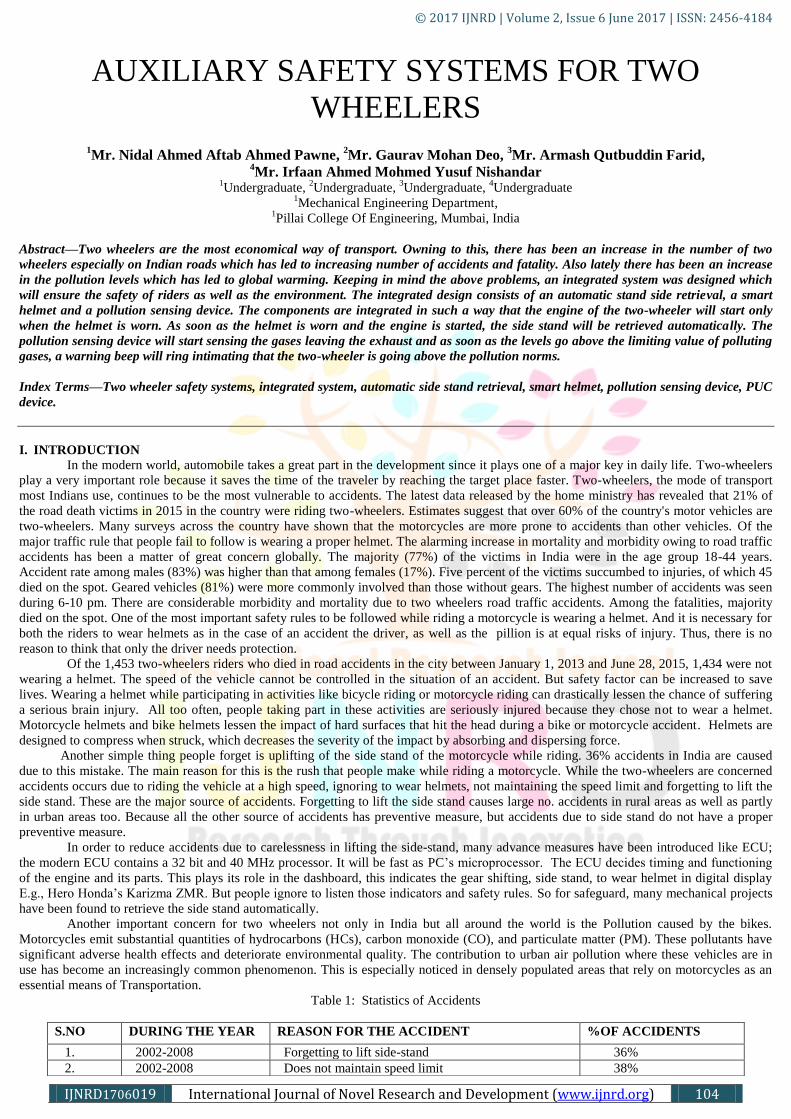
Axle: Axle is the metallic rod made up of mild steel. It connects the lifting lever and sprocket centrally. The axle is welded centrally to the
sprocket. The axle is hold by a holder. The holder is welded with the frame. The holder is used to prevent vibration and to provide support to
the axle. The metal plate is welded perpendicular to the tube. The diameter of tube is slightly greater than the axle diameter. This is for
allowing the axle to rotate freely without friction with the tube. The other end of the metal plate is welded at the frame. The one end of axle
is welded with sprocket and other end with lifting lever and thus the power is transmitted from sprocket to lifting lever.
Fig 4.1 Axle
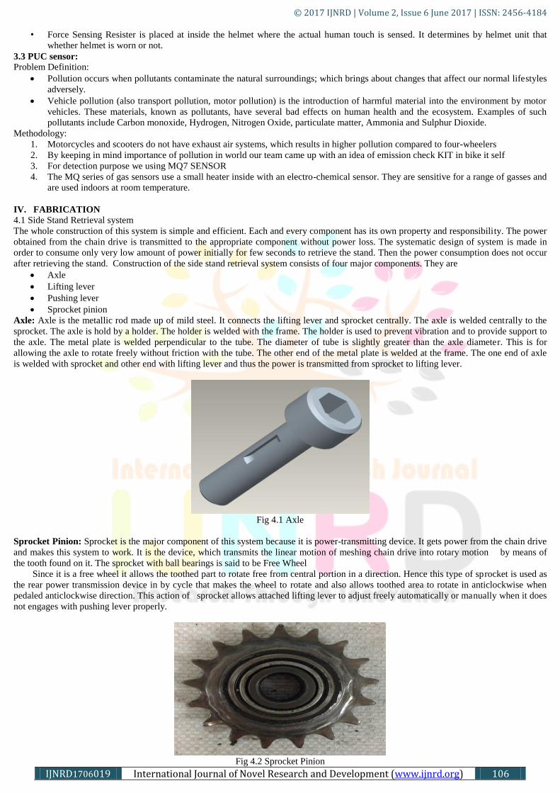
Sprocket Pinion: Sprocket is the major component of this system because it is power-transmitting device. It gets power from the chain drive
and makes this system to work. It is the device, which transmits the linear motion of meshing chain drive into rotary motion by means of
the tooth found on it. The sprocket with ball bearings is said to be Free Wheel
Since it is a free wheel it allows the toothed part to rotate free from central portion in a direction. Hence this type of sprocket is used as
the rear power transmission device in by cycle that makes the wheel to rotate and also allows toothed area to rotate in anticlockwise when
pedaled anticlockwise direction. This action of sprocket allows attached lifting lever to adjust freely automatically or manually when it does
not engages with pushing lever properly.
Fig 4.2 Sprocket Pinion

© 2017 IJNRD | Volume 2, Issue 6 June 2017 | ISSN: 2456-4184
IJNRD1706019 International Journal of Novel Research and Development (www.ijnrd.org) 107
Fig 4.3 Sprocket
Since the sprocket transmit the power from chain drive, it should have the capability to withstand the heavy loads of engine. So to
withstand those impacts on toothed area, It is made of high carbon steel. The ball bearings are made up of high chromium steel.
Lifting Lever: Lifting lever is the third major component of the system .the lifting lever is the rectangular rod made of ms-rod, which
consists of two lifting leaves, which is mounted with the edge of axle. The lifting leaves should be parallel to the sprocket pinion. The lifting
lever is composed of two metal rods, where both are welded at either sides of the axle. The free ends of the lifting leaves are tapered well.
The ends are machined well for tapered shape for smooth engaging with pushing lever.
Fig 4.4 Lifting Lever
This smooth engagement leads proper retrieving of side-stand. This tapered surface makes the lifting lever as capable to withstand
engine impact. When stand is moved vertical in position, the pushing lever engages with lifting leaves. This may not possible in all time,
since the angle of lifting lever may be any degree. So due to effect of free wheel and tapered surface of the lifting lever can adjust itself.
PUSHING LEVER: Pushing lever is the component pivoted centrally to the side stand. The pushing lever is metallic rectangular plate,
whose bottom end is bent in shape of C and top end is welded with a small piece of rectangular rod. This small piece of rod is used for
getting lifted by the lifting lever. Since this rod engages (or) lays over tapered edge of lifting lever, thus the retrieving occur smoothly.
Fig 4.5 Pushing Lever
Specification of Sprocket:
Table 4.1: Specification of Sprocket
MATERIAL High Carbon Steel
PITCH 12.7mm
WIDTH 30mm
TEETH 16
BALLS High carbon high chromium steel balls
© 2017 IJNRD | Volume 2, Issue 6 June 2017 | ISSN: 2456-4184
IJNRD1706019 International Journal of Novel Research and Development (www.ijnrd.org) 108
SPECIFICATION OF AXLE:
Table 4.2: Specification of Axle
MATERIAL Mild Steel
SHAPE Cylindrical rod
LENGTH 50mm
DIAMETER 13mm
INNER DIAMETER OF SUPPORTING AXLE 15 mm
OUTER DIAMETER OF SUPPORTING AXLE 17mm
LENGTH 30mm
THICKNESS 3mm
SPECIFICATION OF LIFTING LEVER:
Table 4.3: Specification of Lifting Lever
LENGTH OF LEVER 95mm
THICKNESS 10mm
TAPERED ANGLE 45deg
CHAMFERED ANGLE 20deg
POSITION Parallel to Sprocket
WELDED LENGTH 13mm
MATERIAL USED Mild Steel
SPECIFICATION OF PUSHING LEVER:
Table 4.4: Specification of Pushing Lever
MATERIAL Mild Steel
LENGTH OF LEVER 180mm
THICKNESS 3mm
DIAMETER OF HOLE 8mm
LENGTH 30mm
THICKNESS 10mm
DIAMETER OF CLAMP 28mm
DIAMETER OF STAND 25mm
PIVOTED ANGLE 55deg
BOLT DIAMETER 8mm
ASSEMBLY OF COMPONENTS: For the functioning of system the above four components are arranged in two assembly which is
described below,
Inciter assembly
Retriever assembly
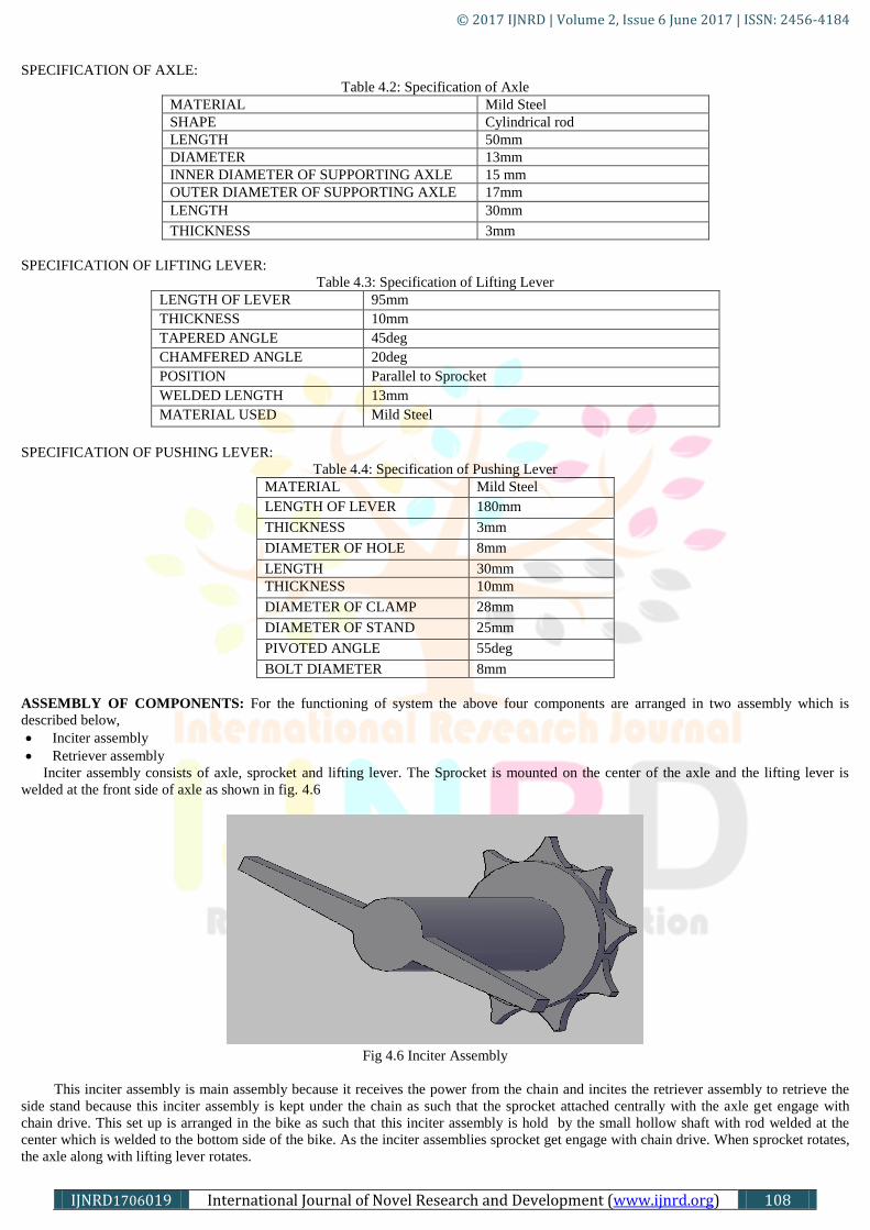
Inciter assembly consists of axle, sprocket and lifting lever. The Sprocket is mounted on the center of the axle and the lifting lever is
welded at the front side of axle as shown in fig. 4.6
Fig 4.6 Inciter Assembly
This inciter assembly is main assembly because it receives the power from the chain and incites the retriever assembly to retrieve the
side stand because this inciter assembly is kept under the chain as such that the sprocket attached centrally with the axle get engage with
chain drive. This set up is arranged in the bike as such that this inciter assembly is hold by the small hollow shaft with rod welded at the
center which is welded to the bottom side of the bike. As the inciter assemblies sprocket get engage with chain drive. When sprocket rotates,
the axle along with lifting lever rotates.
© 2017 IJNRD | Volume 2, Issue 6 June 2017 | ISSN: 2456-4184
IJNRD1706019 International Journal of Novel Research and Development (www.ijnrd.org) 109
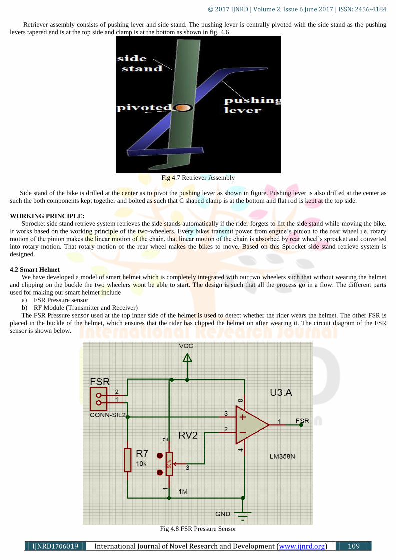
Retriever assembly consists of pushing lever and side stand. The pushing lever is centrally pivoted with the side stand as the pushing
levers tapered end is at the top side and clamp is at the bottom as shown in fig. 4.6
Fig 4.7 Retriever Assembly
Side stand of the bike is drilled at the center as to pivot the pushing lever as shown in figure. Pushing lever is also drilled at the center as
such the both components kept together and bolted as such that C shaped clamp is at the bottom and flat rod is kept at the top side.
WORKING PRINCIPLE:
Sprocket side stand retrieve system retrieves the side stands automatically if the rider forgets to lift the side stand while moving the bike.
It works based on the working principle of the two-wheelers. Every bikes transmit power from engine’s pinion to the rear wheel i.e. rotary
motion of the pinion makes the linear motion of the chain. that linear motion of the chain is absorbed by rear wheel’s sprocket and converted
into rotary motion. That rotary motion of the rear wheel makes the bikes to move. Based on this Sprocket side stand retrieve system is
designed.
4.2 Smart Helmet
We have developed a model of smart helmet which is completely integrated with our two wheelers such that without wearing the helmet
and clipping on the buckle the two wheelers wont be able to start. The design is such that all the process go in a flow. The different parts
used for making our smart helmet include
a) FSR Pressure sensor
b) RF Module (Transmitter and Receiver)
The FSR Pressure sensor used at the top inner side of the helmet is used to detect whether the rider wears the helmet. The other FSR is
placed in the buckle of the helmet, which ensures that the rider has clipped the helmet on after wearing it. The circuit diagram of the FSR
sensor is shown below.
Fig 4.8 FSR Pressure Sensor

© 2017 IJNRD | Volume 2, Issue 6 June 2017 | ISSN: 2456-4184
IJNRD1706019 International Journal of Novel Research and Development (www.ijnrd.org) 110
The RF module we used has two parts to it, one is the transmitter and the second is the receiver. The transmitter senses whether or not
the helmet is worn and sends the signal to the receiver while the receiver waits for the signal and then allows the two wheelers to be
started .The transmitter circuit diagram is shown below.
Fig 4.9 RF Module Transmitter
The receiver circuit is shown below.
Fig 4.10 RF Module Receiver
Components Used:
RF Link Transmitter
RF Link Receiver
Battery
Resistors
LED’s
Relay
FSR Sensor

© 2017 IJNRD | Volume 2, Issue 6 June 2017 | ISSN: 2456-4184
IJNRD1706019 International Journal of Novel Research and Development (www.ijnrd.org) 111
Fig 4.11: RF Link Transmitter - 434MHz
These wireless transmitters work with our 434MHz receivers. They can easily fit into a breadboard and work well with micro-controllers
to create a very simple wireless data link. Since these are only transmitters, they will only work communicating data one-way, you would
need two pairs (of different frequencies) to act as transmitter/receiver pair. These modules are indiscriminate and will receive a fair amount
of noise. Both the transmitter and receiver work at common frequencies and don’t have IDs. Therefore, a method of filtering this noise and
pairing transmitter and receiver will be necessary. The example code below shows such an example for basic operation. Please refer to the
example code and links below for ways to accomplish a robust wireless data link.
Some important features of RF transmitter 434MHZ are as follows:
434 MHz
500ft range (given perfect conditions)
4800bps data rate
5V supply voltage
RF Link Receiver - (434MHz):
These wireless receivers work with our 434MHz transmitters. They can easily fit into a breadboard and work well with micro-
controllers to create a very simple wireless data link. Since these are only receivers, they will only work communicating data one-way, you
would need two pairs (of different frequencies) to act as a transmitter/receiver pair.
Fig 4.12: RF Link Receiver - 434MHz
These modules are indiscriminate and will receive a fair amount of noise. Both the transmitter and receiver work at common
frequencies and don’t have IDs. Therefore, a method of filtering this noise and pairing transmitter and receiver will be necessary. The
example code below shows such an example for basic operation. Please refer to the example code and links below for ways to accomplish a
robust wireless data link. Some important features of 434MHz RF receiver are as follows:
434 MHz
500ft range (given perfect conditions)
4800bps data rate
5V supply voltage
General physics of radio signals:
RF communication works by creating electromagnetic waves at a source and being able to pick up those electromagnetic waves at a
particular destination. These electromagnetic waves travel through the air at near the speed of light. The wavelength of an electromagnetic
signal is inversely proportional to the frequency; the higher the frequency, the shorter the wavelength.
Frequency is measured in Hertz (cycles per second) and radio frequencies are measured in kilohertz (KHz or thousands of cycles per second),
megahertz (MHz or millions of cycles per second) and gigahertz (GHz or billions of cycles per second). Higher frequencies result in shorter
wavelengths. The wavelength for a 900 MHz device is longer than that of a 2.4 GHz device. In general, signals with longer wavelengths
travel a greater distance and penetrate through, and around objects better than signals with shorter wavelengths.
How does an RF communication system work?
Imagine an RF transmitter wiggling an electron in one location. This wiggling electron causes a ripple effect, somewhat akin to dropping a
pebble in a pond. The effect is an electromagnetic (EM) wave that travels out from the initial location resulting in electrons wiggling in
remote locations. An RF receiver can detect this remote electron wiggling.
The RF communication system then utilizes this phenomenon by wiggling electrons in a specific pattern to represent information. The
receiver can make this same information available at a remote location; communicating with no wires. In most wireless systems, a designer
has two overriding constraints: it must operate over a certain distance (range) and transfer a certain amount of information within a time
frame (data rate).
How is range determined?
dB - Decibels

© 2017 IJNRD | Volume 2, Issue 6 June 2017 | ISSN: 2456-4184
IJNRD1706019 International Journal of Novel Research and Development (www.ijnrd.org) 112
Decibels are logarithmic units that are often used to represent RF power. To convert from watts to dB: Power in dB = 10* (log x) where x is
the power in watts.
Another unit of measure that is encountered often is dBm (dB milliwatts). The conversion formula for it is Power in dBm = 10* (log x)
where x is the power in milliwatts.
4.3 PUC Sensor
Sensitive material of MQ-7 gas sensor is SnO2, which with lower conductivity in clean air. It make detection by method of cycle high
and low temperature, and detect CO when low temperature (heated by 1.5V). The sensor’s conductivity is more higher along with the gas
concentration rising. When high temperature (heated by 5.0V), it cleans the other gases adsorbed under low temperature. Please use simple
electrocircuit, Convert change of conductivity to correspond output signal of gas concentration.
MQ-7 gas sensor has high sensitivity to Carbon Monoxide. The sensor could be used to detect different gases contains CO, it is with low cost
and suitable for different application.
Character
Good sensitivity to Combustible gas in wide range
High sensitivity to Natural gas
Long life and low cost
Simple drive circuit
Application
Domestic gas leakage detector
Industrial CO detector
Portable gas detector
Fig 4.13: MQ7 Circuit
The above is basic test circuit of the sensor. The sensor need to be put 2 voltage, heater voltage (VH)and test voltage(VC). VH used to
supply certified working temperature to the sensor, while VC used to detect voltage (VRL) on load resistance (RL) whom is in series with
sensor. The sensor has light polarity, Vc need DC power. VC and VH could use same power circuit with precondition to assure performance
of sensor. In order to make the sensor with better performance, suitable RL value is needed: Power of Sensitivity body(Ps):
Ps=Vc2
×Rs/(Rs+RL)2
Fig. 4.14: MQ7 Sensor Parts
Structure and configuration of MQ-7 gas sensor is shown as Fig, sensor composed by micro AL2O3 ceramic tube, Tin Dioxide (SnO2)
sensitive layer, measuring electrode and heater are fixed into a crust made by plastic and stainless steel net. The heater provides necessary
work conditions for work of sensitive components. The enveloped MQ-7 have 6 pin, 4 of them are used to fetch signals, and other 2 are used
for providing heating current.
4.4 Integration:
© 2017 IJNRD | Volume 2, Issue 6 June 2017 | ISSN: 2456-4184
IJNRD1706019 International Journal of Novel Research and Development (www.ijnrd.org) 113
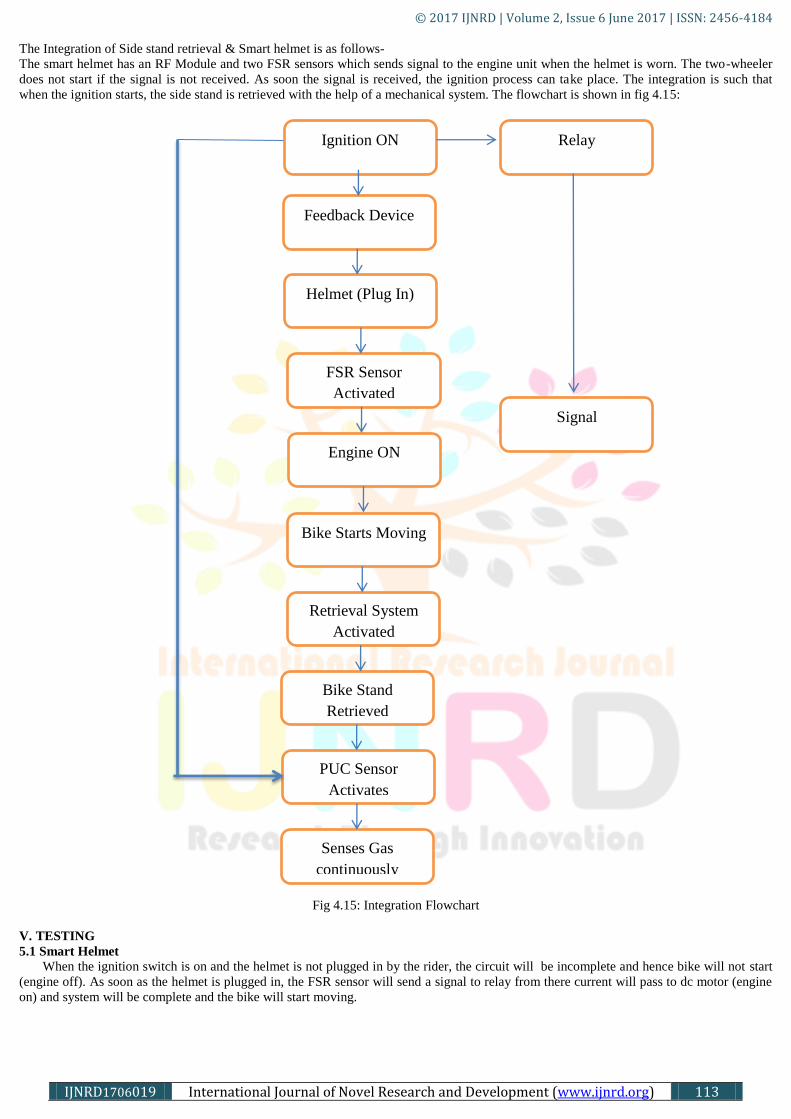
The Integration of Side stand retrieval & Smart helmet is as follows-
The smart helmet has an RF Module and two FSR sensors which sends signal to the engine unit when the helmet is worn. The two-wheeler
does not start if the signal is not received. As soon the signal is received, the ignition process can take place. The integration is such that
when the ignition starts, the side stand is retrieved with the help of a mechanical system. The flowchart is shown in fig 4.15:
Fig 4.15: Integration Flowchart
V. TESTING
5.1 Smart Helmet
When the ignition switch is on and the helmet is not plugged in by the rider, the circuit will be incomplete and hence bike will not start
(engine off). As soon as the helmet is plugged in, the FSR sensor will send a signal to relay from there current will pass to dc motor (engine
on) and system will be complete and the bike will start moving.
Ignition ON
Feedback Device
Helmet (Plug In)
FSR Sensor
Activated
Engine ON
Bike Starts Moving
Retrieval System
Activated
Bike Stand
Retrieved
PUC Sensor
Activates
Senses Gas
continuously
Relay
Signal
© 2017 IJNRD | Volume 2, Issue 6 June 2017 | ISSN: 2456-4184
IJNRD1706019 International Journal of Novel Research and Development (www.ijnrd.org) 114
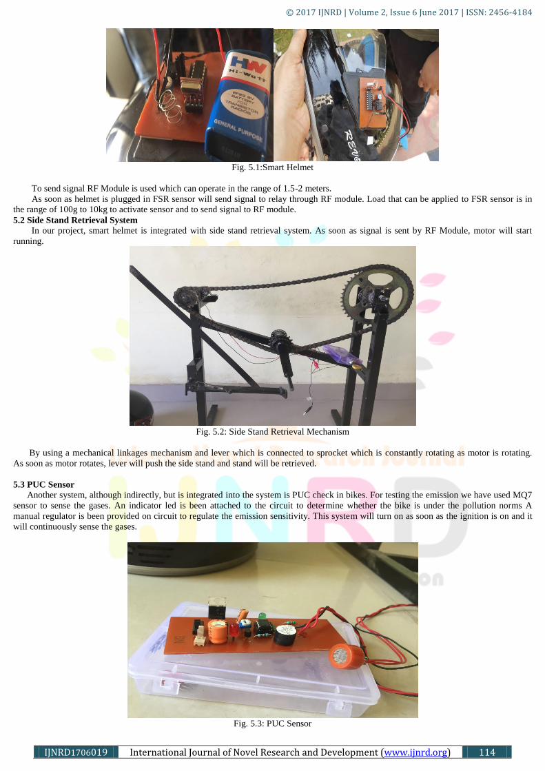
Fig. 5.1:Smart Helmet
To send signal RF Module is used which can operate in the range of 1.5-2 meters.
As soon as helmet is plugged in FSR sensor will send signal to relay through RF module. Load that can be applied to FSR sensor is in
the range of 100g to 10kg to activate sensor and to send signal to RF module.
5.2 Side Stand Retrieval System
In our project, smart helmet is integrated with side stand retrieval system. As soon as signal is sent by RF Module, motor will start
running.
Fig. 5.2: Side Stand Retrieval Mechanism
By using a mechanical linkages mechanism and lever which is connected to sprocket which is constantly rotating as motor is rotating.
As soon as motor rotates, lever will push the side stand and stand will be retrieved.
5.3 PUC Sensor
Another system, although indirectly, but is integrated into the system is PUC check in bikes. For testing the emission we have used MQ7
sensor to sense the gases. An indicator led is been attached to the circuit to determine whether the bike is under the pollution norms A
manual regulator is been provided on circuit to regulate the emission sensitivity. This system will turn on as soon as the ignition is on and it
will continuously sense the gases.
Fig. 5.3: PUC Sensor
© 2017 IJNRD | Volume 2, Issue 6 June 2017 | ISSN: 2456-4184
IJNRD1706019 International Journal of Novel Research and Development (www.ijnrd.org) 115
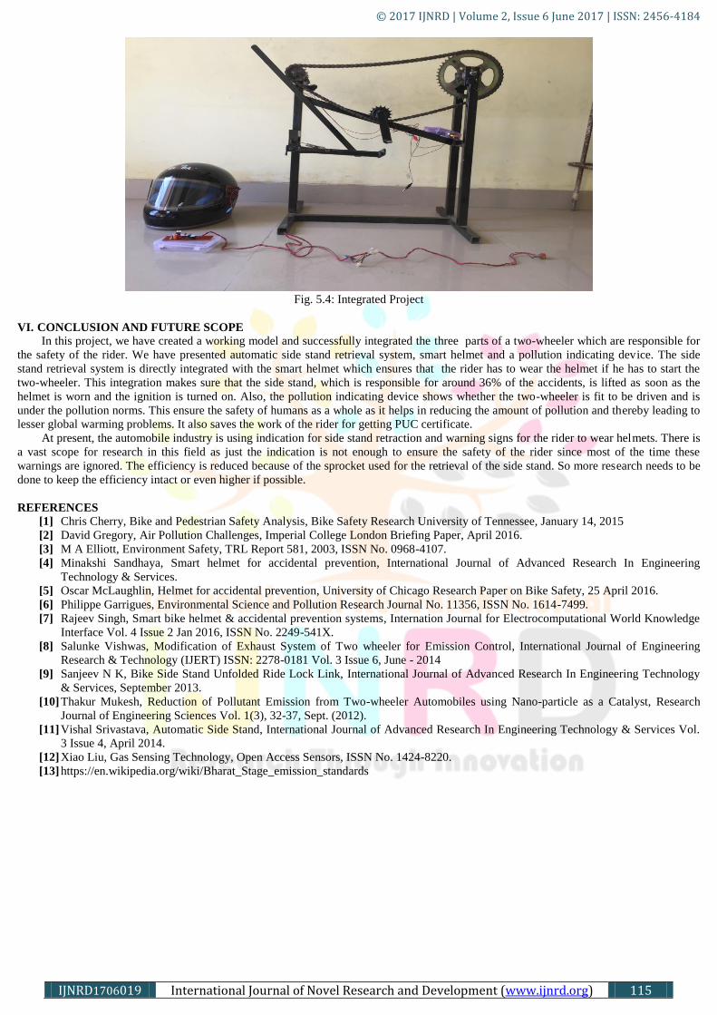
Fig. 5.4: Integrated Project
VI. CONCLUSION AND FUTURE SCOPE
In this project, we have created a working model and successfully integrated the three parts of a two-wheeler which are responsible for
the safety of the rider. We have presented automatic side stand retrieval system, smart helmet and a pollution indicating device. The side
stand retrieval system is directly integrated with the smart helmet which ensures that the rider has to wear the helmet if he has to start the
two-wheeler. This integration makes sure that the side stand, which is responsible for around 36% of the accidents, is lifted as soon as the
helmet is worn and the ignition is turned on. Also, the pollution indicating device shows whether the two-wheeler is fit to be driven and is
under the pollution norms. This ensure the safety of humans as a whole as it helps in reducing the amount of pollution and thereby leading to
lesser global warming problems. It also saves the work of the rider for getting PUC certificate.
At present, the automobile industry is using indication for side stand retraction and warning signs for the rider to wear helmets. There is
a vast scope for research in this field as just the indication is not enough to ensure the safety of the rider since most of the time these
warnings are ignored. The efficiency is reduced because of the sprocket used for the retrieval of the side stand. So more research needs to be
done to keep the efficiency intact or even higher if possible.
REFERENCES
[1] Chris Cherry, Bike and Pedestrian Safety Analysis, Bike Safety Research University of Tennessee, January 14, 2015
[2] David Gregory, Air Pollution Challenges, Imperial College London Briefing Paper, April 2016.
[3] M A Elliott, Environment Safety, TRL Report 581, 2003, ISSN No. 0968-4107.
[4] Minakshi Sandhaya, Smart helmet for accidental prevention, International Journal of Advanced Research In Engineering
Technology & Services.
[5] Oscar McLaughlin, Helmet for accidental prevention, University of Chicago Research Paper on Bike Safety, 25 April 2016.
[6] Philippe Garrigues, Environmental Science and Pollution Research Journal No. 11356, ISSN No. 1614-7499.
[7] Rajeev Singh, Smart bike helmet & accidental prevention systems, Internation Journal for Electrocomputational World Knowledge
Interface Vol. 4 Issue 2 Jan 2016, ISSN No. 2249-541X.
[8] Salunke Vishwas, Modification of Exhaust System of Two wheeler for Emission Control, International Journal of Engineering
Research & Technology (IJERT) ISSN: 2278-0181 Vol. 3 Issue 6, June - 2014
[9] Sanjeev N K, Bike Side Stand Unfolded Ride Lock Link, International Journal of Advanced Research In Engineering Technology
& Services, September 2013.
[10] Thakur Mukesh, Reduction of Pollutant Emission from Two-wheeler Automobiles using Nano-particle as a Catalyst, Research
Journal of Engineering Sciences Vol. 1(3), 32-37, Sept. (2012).
[11] Vishal Srivastava, Automatic Side Stand, International Journal of Advanced Research In Engineering Technology & Services Vol.
3 Issue 4, April 2014.
[12] Xiao Liu, Gas Sensing Technology, Open Access Sensors, ISSN No. 1424-8220.
[13] https://en.wikipedia.org/wiki/Bharat_Stage_emission_standards

![Tvs Two Wheelers -Marketing-rajesh[1][1].Project](https://static.fdocuments.in/doc/165x107/577cc04e1a28aba7118f9e25/tvs-two-wheelers-marketing-rajesh11project.jpg)