
Virtualization Guide for Cisco Unified ICM/Contact Center ... · Chapter Description Explains how...
43
Virtualization Guide for Cisco Unified ICM/Contact Center Enterprise & Hosted Release 7.5(3) July 2010 Americas Headquarters Cisco Systems, Inc. 170 West Tasman Drive San Jose, CA 95134-1706 USA http://www.cisco.com Tel: 408 526-4000 800 553-NETS (6387) Fax: 408 527-0833
Transcript of Virtualization Guide for Cisco Unified ICM/Contact Center ... · Chapter Description Explains how...

Virtualization Guide
for Cisco Unified ICM/Contact Center Enterprise & HostedRelease 7.5(3)
July 2010
Americas Headquarters
Cisco Systems, Inc.
170 West Tasman Drive
San Jose, CA 95134-1706
USA
http://www.cisco.com
Tel: 408 526-4000
800 553-NETS (6387)
Fax: 408 527-0833

THE SPECIFICATIONS AND INFORMATION REGARDING THE PRODUCTS IN THIS MANUAL ARE SUBJECT TO CHANGE WITHOUT NOTICE.ALL STATEMENTS, INFORMATION, AND RECOMMENDATIONS IN THIS MANUAL ARE BELIEVED TO BE ACCURATE BUT ARE PRESENTEDWITHOUT WARRANTY OF ANY KIND, EXPRESS OR IMPLIED. USERS MUST TAKE FULL RESPONSIBILITY FOR THEIR APPLICATION OFANY PRODUCTS.THE SOFTWARE LICENSE AND LIMITED WARRANTY FOR THE ACCOMPANYING PRODUCT ARE SET FORTH IN THE INFORMATION PACKETTHAT SHIPPED WITH THE PRODUCT AND ARE INCORPORATED HEREIN BY THIS REFERENCE. IF YOU ARE UNABLE TO LOCATE THESOFTWARE LICENSE OR LIMITED WARRANTY, CONTACT YOUR CISCO REPRESENTATIVE FOR A COPY.The Cisco implementation of TCP header compression is an adaptation of a program developed by the University of California, Berkeley (UCB) aspart of UCBs public domain version of the UNIX operating system. All rights reserved. Copyright 1981, Regents of the University of California.NOTWITHSTANDING ANY OTHER WARRANTY HEREIN, ALL DOCUMENT FILES AND SOFTWARE OF THESE SUPPLIERS ARE PROVIDED"AS IS" WITH ALL FAULTS. CISCO AND THE ABOVE-NAMED SUPPLIERS DISCLAIM ALL WARRANTIES, EXPRESSED OR IMPLIED, INCLUDING,WITHOUT LIMITATION, THOSE OF MERCHANTABILITY, FITNESS FOR A PARTICULAR PURPOSE AND NONINFRINGEMENT OR ARISINGFROM A COURSE OF DEALING, USAGE, OR TRADE PRACTICE.IN NO EVENT SHALL CISCO OR ITS SUPPLIERS BE LIABLE FOR ANY INDIRECT, SPECIAL, CONSEQUENTIAL, OR INCIDENTAL DAMAGES,INCLUDING, WITHOUT LIMITATION, LOST PROFITS OR LOSS OR DAMAGE TO DATA ARISING OUT OF THE USE OR INABILITY TO USETHIS MANUAL, EVEN IF CISCO OR ITS SUPPLIERS HAVE BEEN ADVISED OF THE POSSIBILITY OF SUCH DAMAGES.Cisco and the Cisco Logo are trademarks of Cisco Systems, Inc. and/or its affiliates in the U.S. and other countries. A listing of Cisco's trademarkscan be found at http://www.cisco.com/go/trademarks. Third party trademarks mentioned are the property of their respective owners. The use ofthe word partner does not imply a partnership relationship between Cisco and any other company. (1005R)Any Internet Protocol (IP) addresses used in this document are not intended to be actual addresses. Any examples, command display output, andfigures included in the document are shown for illustrative purposes only. Any use of actual IP addresses in illustrative content is unintentional andcoincidental.Copyright 2010 Cisco Systems, Inc. All rights reserved.
Table of Contents
Preface ...........................................................................................................................................................1Purpose .....................................................................................................................................................1Audience ....................................................................................................................................................1Organization ..............................................................................................................................................1Related Documentation .............................................................................................................................2Conventions................................................................................................................................................2Obtaining Documentation and Submitting a Service Request...................................................................3Documentation Feedback...........................................................................................................................3
1. Overview.....................................................................................................................................................5
2. Deployment Configuration Considerations..................................................................................................7Supported and Not Supported PGs on Virtual Machines...........................................................................7Configuration Considerations for the PGs..................................................................................................7Configuration Considerations for the Agent PGs........................................................................................8Configuration Considerations for the Unified CCE Gateway PG................................................................9Configuration Considerations for the VRU PGs..........................................................................................9Configuration Considerations for the MR PG.............................................................................................9Configuration Considerations for the Time Division Multiplexing (TDM) ACDs PG..................................10Configuration Considerations for the Client AWs.....................................................................................10
3. Virtualization Management Tools..............................................................................................................11
4. Installation and Configuration of the ESX Server and VMware Management Tools..................................13Installing the ESX Server Hardware.........................................................................................................13Configuring ESX Hardware......................................................................................................................13Installing and Configuring the ESX Software............................................................................................14Installing and Configuring VMware Management Tools............................................................................16
5. Configuring the Virtual Machines..............................................................................................................17Virtual Machine Properties for the PG......................................................................................................17Virtual Machine Properties for the Client AW...........................................................................................18Virtual Machine Resource Management Considerations.........................................................................19
Examples of CPU Affinity Scheduling for Agent PG VM......................................................................19ESX CPU Affinity Scheduling for the Client AW VMs Co-Resident with the PG VMs..........................20Virtual Machine Resource Management Default Settings...................................................................20
Virtual Machine Network Configuration....................................................................................................21Configuring the VM Network................................................................................................................21Virtual Machine Network Configuration for the PGs............................................................................22Virtual Machine Network Configuration for the Client AWs..................................................................26Virtual Machine Network Configuration for a Mix of PGs and Client AWs...........................................28
Installing the VMware Tools......................................................................................................................30Installing ICM Components on a Virtual Machine.....................................................................................31Remote Control of the Virtual Machines...................................................................................................31System Monitoring....................................................................................................................................31
6. System Backup and Migration...................................................................................................................33Backup and Restore Technique................................................................................................................33
Backup by Copying the Virtual Machine Folder...................................................................................33Restore VM from a VM Backup Folder.................................................................................................34
Migrating the VMs to another Host by Cloning.........................................................................................34
Virtualization Guide for Cisco Unified ICM/Contact Center Enterprise & Hosted Release 7.5(3)
i

7. Unsupported Features and Configurations...............................................................................................35VMware Features.....................................................................................................................................35Unified CCE Components/Features on Virtual Machine..........................................................................36SAN, iSCSI, and NAS...............................................................................................................................36
Index .............................................................................................................................................................37
Virtualization Guide for Cisco Unified ICM/Contact Center Enterprise & Hosted Release 7.5(3)
ii

List of Figures
Figure 1: VMware ESX Server Network Components and Connections for 4 PGs........................................................22
Figure 2: Example of ESX Networking Configuration for 4 PGs, Side - A....................................................................24
Figure 3: VMware ESX Server Network Components and Connections for 7 PGs........................................................25
Figure 4: Example of ESX Networking Configuration for 7 PGS, Side - A...................................................................26
Figure 5: VMware ESX Server Network Components and Connections for the Client AWs.........................................27
Figure 6: Example of ESX Networking Configuration for 20 Client AWs.....................................................................28
Figure 7: VMware ESX Server Network Components and Connections for 2 PGs and 6 Client AWs..........................29
Figure 8: Example of ESX Networking Configuration for 2 PGs and 6 Client AWs......................................................30
Virtualization Guide for Cisco Unified ICM/Contact Center Enterprise & Hosted Release 7.5(3)
iii

Virtualization Guide for Cisco Unified ICM/Contact Center Enterprise & Hosted Release 7.5(3)
iv

Preface
Purpose
This manual provides information to help you understand, install, and implement theVirtualization Solution. The Virtualization Solution is supported for Cisco Unified IntelligentContact Management (Unified ICM) and Cisco Unified Contact Center Enterprise (UnifiedCCE).
Audience
This document is intended for the users of Unified ICM software, implementing the VirtualizationSolution for Unified ICM and Unified CCE.
Organization
The following table describes the information contained in each chapter of this guide.
DescriptionChapter
A brief overview of the Virtualization Solution.Chapter 1: Overview (page 5)
Discusses deployment configuration considerations for PGsand Client AWs on a VMware platform.
Chapter 2: Deployment Configuration Considerations (page7)
Describes the Virtualization management tools.Chapter 3: Virtualization Management Tools (page 11)
Explains the steps required to configure the ESX Server,explains the installation of VMware Management Tools.
Chapter 4: Installation and Configuration of the ESX Serverand VMware Management Tools (page 13)
Virtualization Guide for Cisco Unified ICM/Contact Center Enterprise & Hosted Release 7.5(3)
1

DescriptionChapter
Explains how to configure and install ICM components ona Virtual machine. Explains the procedure to remote controland monitor a Virtual machine.
Chapter 5: Configuring the Virtual Machines (page 17)
Explains the procedures to backup the Virtual Machines.Chapter 6: System Backup and Migration (page 33)
Lists the features that are not supported on the UnifiedICM/CCE virtualized platform.
Chapter 7: Unsupported Features and Configurations (page35)
Related Documentation
Documentation for the Cisco Unified ICM/CCE software and related documentation, is accessiblefrom Cisco.com at: www.cisco.com (http://www.cisco.com/web/psa/products/index.html?c=278875240)
Conventions
This manual uses the following conventions:
DescriptionConvention
Boldface font is used to indicate commands, such as user entries,keys, buttons, and folder and submenu names. For example:
boldface font
• Choose Edit > Find.
• Click Finish.
Italic font is used to indicate the following:italic font
• To introduce a new term. Example: A skill group is acollection of agents who share similar skills.
• For emphasis. Example: Do not use the numerical namingconvention.
• A syntax value that the user must replace. Example: IF(condition, true-value, false-value)
• A book title. Example: See the Cisco CRS Installation Guide.
Window font, such as Courier, is used for the following:window font
• Text as it appears in code or that the window displays.Example: <html><title>Cisco Systems,Inc. </title></html>
Angle brackets are used to indicate the following:< >
Virtualization Guide for Cisco Unified ICM/Contact Center Enterprise & Hosted Release 7.5(3)
2
Preface
Related Documentation
DescriptionConvention
• For arguments where the context does not allow italic, suchas ASCII output.
• A character string that the user enters but that does not appearon the window such as a password.
Obtaining Documentation and Submitting a Service Request
For information on obtaining documentation, submitting a service request, and gatheringadditional information, see the monthly What's New in Cisco Product Documentation, whichalso lists all new and revised Cisco technical documentation, at:
http://www.cisco.com/en/US/docs/general/whatsnew/whatsnew.html
Subscribe to the What's New in Cisco Product Documentation as a Really Simple Syndication(RSS) feed and set content to be delivered directly to your desktop using a reader application.The RSS feeds are a free service and Cisco currently supports RSS version 2.0.
Documentation Feedback
You can provide comments about this document by sending email to the following address:
mailto:[email protected]
We appreciate your comments.
Virtualization Guide for Cisco Unified ICM/Contact Center Enterprise & Hosted Release 7.5(3)
3
Preface
Obtaining Documentation and Submitting a Service Request

Virtualization Guide for Cisco Unified ICM/Contact Center Enterprise & Hosted Release 7.5(3)
4
Preface
Documentation Feedback

OverviewThe Virtualization Solution enables you to run the Unified ICM/CCE Client AdministratorWorkstations (AWs) and certain Peripheral Gateways (PGs) on VMware’s ESX platform.
This will reduce box count for installations that have multiple PGs at the same location and fordeployments that require multiple separate desktops solely to support Client AWs - for example,a supervisor whose primary machine is running an operating system that is not supported bythe Client AW, needs a separate machine in order to run Client AW. Reduced box count helpsreduce general management overhead.
This manual assumes that you have the proper VMware infrastructure training, and have acquiredthe necessary knowledge and experience regarding deployment and management of VMs. Also,although Cisco has performed due diligence in testing, Cisco does not provide support onVMware products. Contact VMware or VMware partners for all VMware product support andtraining.
Currently Cisco supports virtualization only for Unified ICM/CCE Client AWs and certain PGson VMware’s ESX platform. All other Unified ICM/CCE components, including CallRouter,Logger, AW Distributor, Historical Data Server (HDS), WebView Server, Cisco Agent Desktop(CAD) Server, are at this time not supported running on VMs.
For the Central Processing Unit (CPU) resources to handle critical Call Center operations, oneor more dedicated CPU processors must be allocated to the VMs. To avoid interference fromother non-ICM applications, do not have a co-resident deployment with non-ICM applicationVMs running on the same ESX Server.
The VMs deployed in a Virtualization solution must be run on one of the Cisco servers listedas supported in theHardware & System Software Specification (Bill of Materials) for CiscoUnified ICM/Contact Center Enterprise & Hosted, Release 7.5(x) .
Virtualization Guide for Cisco Unified ICM/Contact Center Enterprise & Hosted Release 7.5(3)
5
Chapter 1

Virtualization Guide for Cisco Unified ICM/Contact Center Enterprise & Hosted Release 7.5(3)
6
Chapter 1: Overview

Deployment Configuration ConsiderationsThis chapter discusses deployment configuration considerations for PGs and Client AWs on aVMware platform.
This chapter contains the following topics:
• Supported and Not Supported PGs on Virtual Machines, page 7• Configuration Considerations for the PGs, page 7• Configuration Considerations for the Agent PGs, page 8• Configuration Considerations for the Unified CCE Gateway PG, page 9• Configuration Considerations for the VRU PGs, page 9• Configuration Considerations for the MR PG, page 9• Configuration Considerations for the Time Division Multiplexing (TDM) ACDs PG, page
10• Configuration Considerations for the Client AWs, page 10
Supported and Not Supported PGs on Virtual Machines
In general, all PGs are supported in the VMware ESX environment with the exception of limitedTDM PG types utilizing non-standard communications links. Additionally, certain PGconfiguration options, such as the MR PG with Outbound Dialer, are unsupported at this time.For detailed information on supported PGs, refer to the section "Server Virtualization" in theHardware and System Software Specification (Bill of Materials) for Cisco Unified ICM/ContactCenter Enterprise & Hosted, available at http://www.cisco.com/en/US/products/sw/custcosw/ps1001/products_user_guide_list.html
Configuration Considerations for the PGs
For PG capacity information and VM resource requirements, refer to the section "ServerHardware Requirements" in the Hardware and System Software Specification (Bill of Materials)
Virtualization Guide for Cisco Unified ICM/Contact Center Enterprise & Hosted Release 7.5(3)
7
Chapter 2

for Cisco Unified ICM/Contact Center Enterprise & Hosted, available at http://www.cisco.com/en/US/products/sw/custcosw/ps1001/products_user_guide_list.html.
The following considerations are applicable to all the PGs in the Virtualization deployment:
• You can install only one PG per VM.
• For hardware redundancy and fault tolerance, you should not place Side A and Side B PGson the same ESX Server. It is required that you have two separate ESX Servers, one foreach side of the PG deployment.
• Assign the same number of vCPUs as the number of assigned processors for the VM in yourESX affinity scheduling. Specify the number of vCPUs during the virtual machine creationand assign processors to the virtual machine after you have created the VM. (A vCPU is avirtual CPU, which is emulated by the ESX Server hypervisor layer.)
Configuration Considerations for the Agent PGs
The Unified CM PG, Unified CCE Generic/System PG, and Unified ICM ARS PG are referredto as Agent PGs in this manual.
The ARS PG provides agent routing services, and it integrates TDM peripherals with ICM.
The following configuration considerations are applicable for deploying Agent PGs on VMs:
• The sizing capacity of the Agent PG VM is based on the “Operating Conditions” and“Additional Sizing Factors” described in the Cisco Unified Contact Center Enterprise 7.5Solution Reference Network Design (SRND) (Chapter: Sizing Unified CCE Components andServers), available at: www.cisco.com (http://www.cisco.com/en/US/docs/voice_ip_comm/cust_contact/contact_center/ipcc_enterprise/srnd/75/ccsrnd75.html.)
• The sizing capacity of the Agent PG VM is based on the CTI OS server being co-residentwith the Agent PG on the same Virtual Machine, and on up to five skill groups per agent.
• You can have only one PIM per Agent PG.
• If there are more than five skill groups per agent, refer to the chapter "Sizing Unified CCEComponents and Servers” in the Cisco Unified Contact Center Enterprise 7.5 SolutionReference Network Design (SRND), available at: www.cisco.com (http://www.cisco.com/en/US/docs/voice_ip_comm/cust_contact/contact_center/ipcc_enterprise/srnd/75/ccsrnd75.html.).
• You cannot install Mobile Agent on Agent PGs running on VMs.
The Agent PG Deployment Configuration is explained via the following examples:
Example 1: Agent PG Deployment with 4 PGs on an ESX Server.
In this configuration,
Virtualization Guide for Cisco Unified ICM/Contact Center Enterprise & Hosted Release 7.5(3)
8
Chapter 2: Deployment Configuration Considerations
Configuration Considerations for the Agent PGs

• There are four Agent PG VMs on an ESX Server, with one Agent PG per VM.
• Three PG VMs have affinity scheduled for two physical processors and 4GB RAM.
• One PG VM has affinity scheduled for one physical processor and 2GB RAM.
Example 2: Agent PG Deployment with seven PGs on an ESX Server.
In this configuration,
• There are seven Agent PG VMs on an ESX Server, with one Agent PG per VM.
• Each of the seven PG VMs has affinity scheduled for one physical processor and 2GB RAM.
Configuration Considerations for the Unified CCE Gateway PG
The following configuration considerations are applicable for deploying the Unified CCEGateway PGs on VMs:
• The maximum number of skill groups per agent on the child is five.
• A Unified CCE Gateway PG can manage multiple child Unified CCE peripherals, with upto five child systems.
For information on general ICM Parent/Child deployment options, refer to the Cisco UnifiedContact Center Enterprise 7.5 Solution Reference Network Design (SRND) (Section"Parent/Child"), available at www.cisco.com (http://www.cisco.com/en/US/docs/voice_ip_comm/cust_contact/contact_center/ipcc_enterprise/srnd/75/ccsrnd75.html.)
Configuration Considerations for the VRU PGs
For VRU PG capacity information and VM resource requirements, refer to the section "ServerHardware Requirements" in the Hardware and System Software Specification (Bill of Materials)for Cisco Unified ICM/Contact Center Enterprise & Hosted, available at http://www.cisco.com/en/US/products/sw/custcosw/ps1001/products_user_guide_list.html.
Configuration Considerations for the MR PG
For the MR PG capacity information and its VM resource requirements, refer to the section"Server Hardware Requirements" in the Hardware and System Software Specification (Bill ofMaterials) for Cisco Unified ICM/Contact Center Enterprise & Hosted, available at http://www.cisco.com/en/US/products/sw/custcosw/ps1001/products_user_guide_list.html.
Note: Deploying an MR PG on a VM in an Outbound Option configuration is not supported.
Virtualization Guide for Cisco Unified ICM/Contact Center Enterprise & Hosted Release 7.5(3)
9
Chapter 2: Deployment Configuration Considerations
Configuration Considerations for the Unified CCE Gateway PG

Configuration Considerations for the Time Division Multiplexing (TDM) ACDs PG
The following considerations are applicable to all the TDM ACD PGs in a Virtualizationdeployment:
• You can install only one PIM per TDM ACD PG.
• The sizing capacity of the TDM ACD PG is based on five skill groups per agent. (The AvayaPG is an exception. See the Hardware and System Software Specification (Bill of Materials)for Cisco Unified ICM/Contact Center Enterprise & Hosted for details.)
• Running the TDM ACD PGs with the MR PG and the Outbound Option Dialer co-residenton the same VM is not supported.
Configuration Considerations for the Client AWs
You must create the Client AW VM using only one vCPU. The ESX CPU affinity schedulingfor Client AW VMs depends on whether you choose to deploy only Client AW VMs, or a mixof Client AW VMs and PG VMs on a single ESX Server.
The two types of Client AW Virtualization deployment options are:
• Client AW Deployment Option 1 (Client AW VMs only)
– In this case, allocate a dedicated ESX Server for running Client AW VMs only. Ensurethat no other application component VMs are running on this ESX Server.
– Only one Client AW per VM.
– The ESX CPU affinity scheduling is not used. The CPU processors are shared among theVMs and are managed by the ESX kernel.
• Client AW Deployment Option 2 (Co-resident with PG VMs)
– You can have Client AW VMs co-resident with PG VMs.
– Since Client AW is co-resident with PG virtual machines, the CPU affinity scheduling isused. Up to two Client AW VMs can share one physical processor, i.e., if you have twoClient AW VMs, you should assign the same processor to both of them.
Virtualization Guide for Cisco Unified ICM/Contact Center Enterprise & Hosted Release 7.5(3)
10
Chapter 2: Deployment Configuration Considerations
Configuration Considerations for the Time Division Multiplexing (TDM) ACDs PG
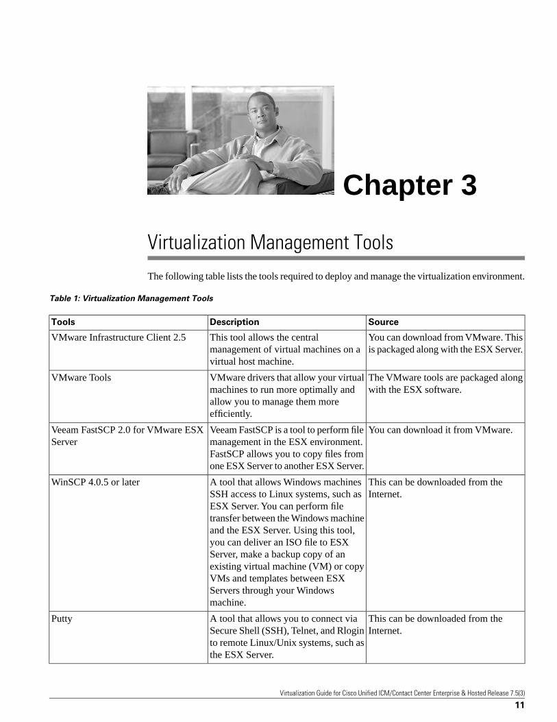
Virtualization Management ToolsThe following table lists the tools required to deploy and manage the virtualization environment.
Table 1: Virtualization Management Tools
SourceDescriptionTools
You can download from VMware. Thisis packaged along with the ESX Server.
This tool allows the centralmanagement of virtual machines on avirtual host machine.
VMware Infrastructure Client 2.5
The VMware tools are packaged alongwith the ESX software.
VMware drivers that allow your virtualmachines to run more optimally and
VMware Tools
allow you to manage them moreefficiently.
You can download it from VMware.Veeam FastSCP is a tool to perform filemanagement in the ESX environment.
Veeam FastSCP 2.0 for VMware ESXServer
FastSCP allows you to copy files fromone ESX Server to another ESX Server.
This can be downloaded from theInternet.
A tool that allows Windows machinesSSH access to Linux systems, such as
WinSCP 4.0.5 or later
ESX Server. You can perform filetransfer between the Windows machineand the ESX Server. Using this tool,you can deliver an ISO file to ESXServer, make a backup copy of anexisting virtual machine (VM) or copyVMs and templates between ESXServers through your Windowsmachine.
This can be downloaded from theInternet.
A tool that allows you to connect viaSecure Shell (SSH), Telnet, and Rlogin
Putty
to remote Linux/Unix systems, such asthe ESX Server.
Virtualization Guide for Cisco Unified ICM/Contact Center Enterprise & Hosted Release 7.5(3)
11
Chapter 3

The optional VMware Virtual Center tool allows the central management of VMs on multiplehost machines, such as virtual machine creation and configuration, remote control, andperformance monitoring. You can obtain this software from VMware.
Refer to the User Manual/Online Help of the respective tools for information on using the tools,or contact VMware or VMware partners for training and support.
Virtualization Guide for Cisco Unified ICM/Contact Center Enterprise & Hosted Release 7.5(3)
12
Chapter 3: Virtualization Management Tools
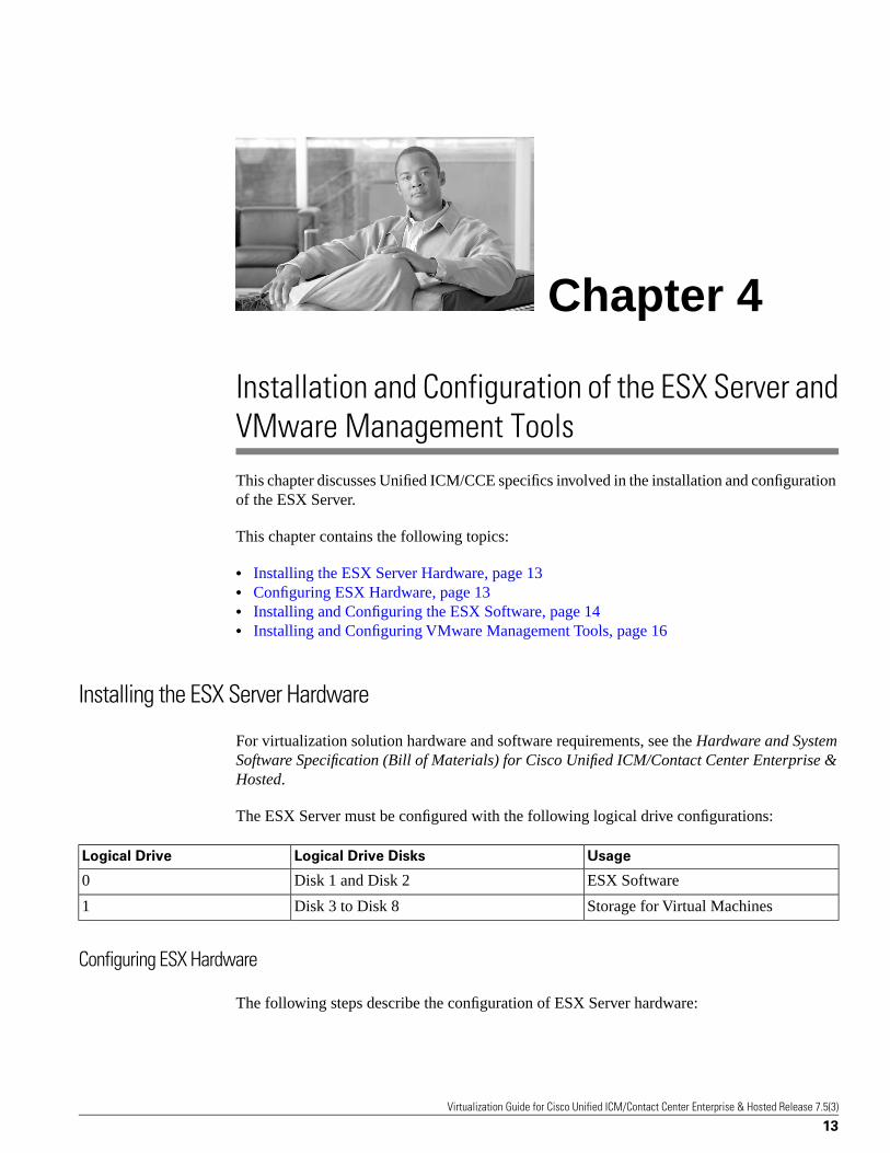
Installation and Configuration of the ESX Server andVMware Management ToolsThis chapter discusses Unified ICM/CCE specifics involved in the installation and configurationof the ESX Server.
This chapter contains the following topics:
• Installing the ESX Server Hardware, page 13• Configuring ESX Hardware, page 13• Installing and Configuring the ESX Software, page 14• Installing and Configuring VMware Management Tools, page 16
Installing the ESX Server Hardware
For virtualization solution hardware and software requirements, see the Hardware and SystemSoftware Specification (Bill of Materials) for Cisco Unified ICM/Contact Center Enterprise &Hosted.
The ESX Server must be configured with the following logical drive configurations:
UsageLogical Drive DisksLogical Drive
ESX SoftwareDisk 1 and Disk 20
Storage for Virtual MachinesDisk 3 to Disk 81
Configuring ESX Hardware
The following steps describe the configuration of ESX Server hardware:
Virtualization Guide for Cisco Unified ICM/Contact Center Enterprise & Hosted Release 7.5(3)
13
Chapter 4

Step 1 Install the additional RAM. The MCS-7845 server (MCS-7845-H2-CCE4 orMCS-7845-I2-CCE4) has 4GB RAM. Additionally, you need to install 16GB RAM in theserver. The Virtualization platform server should have 20GB or more of RAM.
Step 2 Install the additional Ethernet adapters. The MCS-7845 server has two Ethernet ports.Additionally, you need to install two dual Ethernet adapters on the server. This provides a totalof six ethernet ports.
Step 3 Install the server on the rack, and connect the cables for the power, KVM (for keyboard, mouse,and monitor), and the network.
Step 4 Turn on the server.
Step 5 Configure RAID. There are a total of 8 drives on this machine. Drives 1 to 2 are configured asRAID 1, and drives 3 to 8 are configured as RAID 1+0. Here is an example of steps to set upRAID for the MCS-7845-H2-CCE4 server.
a. During startup, hit the "F8" key for ROM configuration.
b. Select the Create Logical Drive menu.
c. Check the drives 1 and 2 and RAID 1+0. (Note: Since there are two disks for logical drive0, the HP Option ROM Configuration for Arrays tool will configure them as RAID 1.)
d. Select Save. This will be the logical drive 0, which is used for the installation of the ESXsoftware.
e. Select the Create Logical Drive menu again.
f. Check drives 3 to 8 and RAID 1+0.
g. Select Save. This will be the logical drive 1, which is used for the storage of the VMs.
h. Reboot the machine.
Installing and Configuring the ESX Software
Note: Before installing the ESX software, refer to the VMware Infrastructure 3 Online Library– ESX Server 3 Edition, available at: www.vmware.com. ( http://pubs.vmware.com/vi35/wwhelp/wwhimpl/js/html/wwhelp.htm)
For information on how to install the ESX software, refer to the section “Installing ESX Server"in the VMware ESX Server 3 Installation Guide, which is available for download at:www.vmware.com. (https://www.vmware.com/pdf/vi3_35/esx_3/r35/vi3_35_25_installation_guide.pdf)
While you navigate through the ESX installer, you will see a screen which allows you to set uppartitions on your logical drives. Select the installation options and the configuration values asdescribed in the following section:
Virtualization Guide for Cisco Unified ICM/Contact Center Enterprise & Hosted Release 7.5(3)
14
Chapter 4: Installation and Configuration of the ESX Server and VMware Management Tools
Installing and Configuring the ESX Software

Partition the logical Drive 0
This logical drive is used for the installation of the ESX software. To create a partition, set theconfiguration values as follows:
Logical Drive 0
• Boot
– Create a new partition on drive 0.
– Select /boot from mount point, ext3 from file system type drop-down menu.
– Allocate 100MB.
– Make Primary.
• Swap
– Create a new partition on drive 0.
– Select Swap from the file system type drop-down menu.
– Allocate 1.5 x RAM size, 30GB for 20GB of physical RAM.
– Make Primary.
• Root
– Edit the free partition on drive 0.
– Select / from mount point, ext3 from the file system type drop-down menu.
– Use the remaining disk space.
– Make Primary.
Partition the logical Drive 1
This logical drive is used for the storage of the VMs.
Logical Drive 1
• Edit the free partition on drive 1.
• Select vmsf3 from file system type drop-down.
• Use the remaining disk space.
• Make Primary.
Configure the network and time zone
Virtualization Guide for Cisco Unified ICM/Contact Center Enterprise & Hosted Release 7.5(3)
15
Chapter 4: Installation and Configuration of the ESX Server and VMware Management Tools
Installing and Configuring the ESX Software

• Enter the IP configuration information for the ESX Server.
• Provide full node and domain name when entering the network name, e.g.,M3P-ESX3.cisco.com. If you do not provide the full name, you may encounter configurationerrors.
• Set the time zone for your location.
Installing and Configuring VMware Management Tools
Install VMware Infrastructure Client on your Windows workstation. You can use this tool tocreate and monitor VMs, make backups, etc.
You have the option to use VirtualCenter to perform administrative tasks for your virtualizedenvironment. If you already have a VirtualCenter installed in your datacenter, you can just addthe ESX hosts or VM cluster to your existing VirtualCenter. Otherwise, you can add theVirtualCenter to your datacenter environment.
To install the VirtualCenter component, follow the VMware Quick Start Guide and the ESXServer 3 Installation Guide.
Virtualization Guide for Cisco Unified ICM/Contact Center Enterprise & Hosted Release 7.5(3)
16
Chapter 4: Installation and Configuration of the ESX Server and VMware Management Tools
Installing and Configuring VMware Management Tools

Configuring the Virtual MachinesRefer to the VMware documentation available at www.vmware.com (http://pubs.vmware.com/vi35/quick_start/wwhelp/wwhimpl/common/html/wwhelp.htm?context=quick_start&file=vi_quick_start_manage.5.1.html), to create VMs forthe PGs and Client AWs. The sections in this chapter include the properties of the PG and ClientAW VMs, information that you will need when you create and configure the VMs. The sectionsalso contain information on configuring networks for VMs.
This chapter contains the following topics:
• Virtual Machine Properties for the PG, page 17• Virtual Machine Properties for the Client AW, page 18• Virtual Machine Resource Management Considerations, page 19• Virtual Machine Network Configuration, page 21• Installing the VMware Tools, page 30• Installing ICM Components on a Virtual Machine, page 31• Remote Control of the Virtual Machines, page 31• System Monitoring, page 31
Virtual Machine Properties for the PG
The PG VM CPU and RAM configurations depend on your capacity requirements. For the PGcapacity information and its VM CPU and RAM requirements, refer to the section "ServerHardware Requirements" in the Hardware and System Software Specification (Bill of Materials)for Cisco Unified ICM/Contact Center Enterprise & Hosted, available at http://www.cisco.com/en/US/products/sw/custcosw/ps1001/products_user_guide_list.html.
When you create the PG VMs, you need to enter the VM properties specified in the table below.
Virtualization Guide for Cisco Unified ICM/Contact Center Enterprise & Hosted Release 7.5(3)
17
Chapter 5

Table 2: PG and IPCC Gateway Virtual Machine Properties
CommentsSettingParameter
see the Hardware and System SoftwareSpecification (Bill of Materials) for
Memory (memory for this VM)
Cisco Unified ICM/Contact CenterEnterprise & Hosted
The number of vCPUs must be thesame as the number of assigned
see the Hardware and System SoftwareSpecification (Bill of Materials) for
CPUs (number of virtual processors)
processors for the VM in your ESXaffinity scheduling.
Cisco Unified ICM/Contact CenterEnterprise & Hosted
1Floppy Drive
CD/DVD drive can be used forinstalling software that is in the ISOformat.
1CD/DVD Drive
One for the private network and one forthe public network
2Network Adapter
LSI LogicSCSI Controller
Disk 1: 25GBHard Disk
For the detailed steps about creating a VM, refer to the VMware Quick Start Guide, availableat: www.vmware.com (http://pubs.vmware.com/vi35/quick_start/wwhelp/wwhimpl/common/html/wwhelp.htm?context=quick_start&file=vi_quick_start_manage.5.1.html). (Refer to thesection "Creating and Managing VMware Infrastructure Components, Creating a VirtualMachine").
Virtual Machine Properties for the Client AW
When you create the Client AW VMs, you need to enter the VM properties specified in thetable below.
Table 3: Client AW Virtual Machine Properties
CommentsSettingParameter
see the Hardware and System SoftwareSpecification (Bill of Materials) for
Memory (memory for this VM)
Cisco Unified ICM/Contact CenterEnterprise & Hosted
See the Configuration Considerationsfor the Client AWs (page 10) sectionfor Client AW VM CPU requirements.
see the Hardware and System SoftwareSpecification (Bill of Materials) forCisco Unified ICM/Contact CenterEnterprise & Hosted
CPUs (number of virtual processors)
1Floppy Drive
1CD/DVD Drive
1Network Adapter
Virtualization Guide for Cisco Unified ICM/Contact Center Enterprise & Hosted Release 7.5(3)
18
Chapter 5: Configuring the Virtual Machines
Virtual Machine Properties for the Client AW

CommentsSettingParameter
LSI LogicSCSI Controller
Disk 1: 10GBHard Disk
Virtual Machine Resource Management Considerations
To achieve consistent system performance, use the VMware ESX CPU affinity scheduling forthe PG VMs and for the Client AW VMs if they are co-resident with the PGs. The ESX CPUaffinity configuration option allows you to allocate dedicated CPU processors to VMs.
For detailed steps to configure the CPU affinity, refer to the VMware Resource ManagementGuide, available at www.vmware.com/support (http://pubs.vmware.com/vi35/resmgmt/wwhelp/wwhimpl/common/html/wwhelp.htm?context=resmgmt&file=vc_advanced_mgmt.11.1.html). (Refer to the section:"Advanced Resource Management, Using CPU affinity to Assign Virtual Machines to SpecificProcessors".)
The processor 0 is used by the VMware ESX kernel and the remaining seven processors areassigned to the VMs that require dedicated CPU processors.
Caution: You must not schedule CPU affinity that assigns processor 0 to any VMs sinceprocessor 0 is used by the ESX kernel.
The following section describes examples of the CPU affinity scheduling for the PG VMs andthe Client AW VMs if they are co-resident with the PG VMs.
Examples of CPU Affinity Scheduling for Agent PG VM
Refer to the sections "Configuration Consideration for the PGs (page 7)" and "ConfigurationConsideration for the Agent PGs (page 8)" regarding the configuration considerations forAgent PGs. The following examples of the CPU affinity scheduling for Agent PG VM are basedon the considerations described in the above sections.
Example 1: In this example, each of the three Agent PG VMs has affinity scheduled for twophysical processors and an Agent PG VM has affinity scheduled for one physical processor.
Note: You must not schedule CPU affinity that assigns processor 0 to any VMs since processor0 is used by the ESX kernel.
Table 4: CPU Affinity Scheduling for Four PG VMs on an ESX Server
ESX CPU Affinity SchedulingVirtual Machine
Processors 1 and 2PG1 VM
Processors 3 and 4PG2 VM
Processors 5 and 6PG3 VM
Processor 7PG4 VM
Virtualization Guide for Cisco Unified ICM/Contact Center Enterprise & Hosted Release 7.5(3)
19
Chapter 5: Configuring the Virtual Machines
Virtual Machine Resource Management Considerations

Example 2: In this example, there are seven Agent PG VMs, and each of these PG VMs hasaffinity scheduled for one physical processor.
Note: You must not schedule CPU affinity that assigns processor 0 to any VMs since processor0 is used by the ESX kernel.
Table 5: CPU Affinity Scheduling for Seven PG VMs
ESX CPU Affinity SchedulingVirtual Machine
Processor 1PG 1 VM
Processor 2PG 2 VM
Processor 3PG 3 VM
Processor 4PG 4 VM
Processor 5PG 5 VM
Processor 6PG 6 VM
Processor 7PG 7 VM
ESX CPU Affinity Scheduling for the Client AW VMs Co-Resident with the PG VMs
If there is a need to have the Client AWs co-resident with PG VMs, then up to two Client AWVMs can share one physical processor, i.e., if you have two Client AW VMs, you should assignthe same processor to both of them. Similarly, you also need to assign dedicated processors tothe PG VMs.
Here is an example of CPU affinity scheduling for four Client AW VMs and other PG VMspresent on the remaining processors (on the same physical ESX Server):
Table 6: CPU Affinity Scheduling for 4 Client AW VMs and 3 PG VMs
ESX CPU Affinity SchedulingVirtual Machine
Processor 1Client AW VM 1
Processor 1Client AW VM 2
Processor 2Client AW VM 3
Processor 2Client AW VM 4
Processors 3 and 4PG VM 1
Processors 5 and 6PG VM 2
Processor 7PG VM 3
Virtual Machine Resource Management Default Settings
There is no need to change the VM resource management configuration default settings. Thefollowing table lists the VM resource management configuration default settings:
Virtualization Guide for Cisco Unified ICM/Contact Center Enterprise & Hosted Release 7.5(3)
20
Chapter 5: Configuring the Virtual Machines
Virtual Machine Resource Management Considerations

Table 7: VM Resource Management Default Settings
LimitReservationSharesParameters
Unlimited0NormalCPU
Unlimited0NormalMemory
NANANormalDisk
Virtual Machine Network Configuration
Configuring the VM Network
To configure the network for the VMs, you create a virtual switch connected to a physical port,then associate the virtual machine's network adapter to this virtual switch.
To Add a vSwitch
1. Login to the ESX host using VMware Infrastructure Client
2. Select the ESX host
3. Click on the Configuration tab
4. Click on Hardware/Networking
5. Click on Add Networking...
6. Select Connection Types: Virtual Machine. Click Next.
7. Select "Create a virtual switch" and select an associated VM NIC.
8. Enter Port Group Properties/Network label: VM Network n, where n is an integer.(Example: "VM Network 1")
9. Click on Finish.
To Associate a VM Network Adapter to Network Connection
1. Edit virtual machine settings.
2. Select the Network Adapter.
3. Select a virtual switch from the Network Connection/network label. (Example: "VMNetwork 1". )
4. Click OK.
Virtualization Guide for Cisco Unified ICM/Contact Center Enterprise & Hosted Release 7.5(3)
21
Chapter 5: Configuring the Virtual Machines
Virtual Machine Network Configuration

Virtual Machine Network Configuration for the PGs
You must configure the VMware ESX Server Network based on the following requirements:
• 1GB Ethernet network is recommended. However, you can also use 100MB Ethernet network.
• Six Ethernet ports are distributed as follows:
– Two ports are provided by the motherboard and one port is connected to the ESX ServiceConsole.
– Among the two dual port Ethernet adapters, one is connected to the ICM private networkand the other is connected to the ICM public network.
• You must follow the section "Server Hardware Configuration Guidelines" in the Hardwareand System Software Specification (Bill of Materials) for Cisco Unified ICM/Contact CenterEnterprise & Hosted to ensure VM network interface port speed/duplex matching the networkswitch port capability.
Figure 1 (page 22) shows an example of VMware ESX Server network components andconnections for the four PGs for Side A. The virtual network for the PG Side B should beconfigured in a similar way. If fewer PGs are deployed, then the network configuration is scaledaccordingly.
Figure 1: VMware ESX Server Network Components and Connections for 4 PGs
In the above example:
Virtualization Guide for Cisco Unified ICM/Contact Center Enterprise & Hosted Release 7.5(3)
22
Chapter 5: Configuring the Virtual Machines
Virtual Machine Network Configuration

• There are four PGs and each PG has two Ethernet connections: one for the private networkand one for the public network.
• There are five virtual switches:
– vSwitch0 – used for the ESX Service Console.
– vSwitch1 – used for the private network connected to two PGs.
– vSwitch2 – used for the private network connected to two PGs.
– vSwitch3 – used for the public network connected to two PGs.
– vSwitch4 – used for the public network connected to two PGs.
Figure 2 (page 24) shows an example of the ESX networking configuration for four PGs, asseen from the VMware Infrastructure Client.
Virtualization Guide for Cisco Unified ICM/Contact Center Enterprise & Hosted Release 7.5(3)
23
Chapter 5: Configuring the Virtual Machines
Virtual Machine Network Configuration

Figure 2: Example of ESX Networking Configuration for 4 PGs, Side - A
Figure 3 (page 25) shows an example of VMware ESX Server network components andconnections for seven PGs for side A. The virtual network for the PG Side B should be configuredin a similar way. If fewer PGs are deployed, then the network configuration is scaled accordingly.
Virtualization Guide for Cisco Unified ICM/Contact Center Enterprise & Hosted Release 7.5(3)
24
Chapter 5: Configuring the Virtual Machines
Virtual Machine Network Configuration

Figure 3: VMware ESX Server Network Components and Connections for 7 PGs
In the above example:
• There are seven PGs and each PG has two Ethernet connections: one for the private networkand one for the public network.
• There are five virtual switches:
– vSwitch0 – used for the ESX Service Console.
– vSwitch1 – used for the private network connected to four PGs.
– vSwitch2 – used for the private network connected to three PGs.
– vSwitch3 – used for the public network connected to four PGs.
– vSwitch4 – used for the public network connected to three PGs.
Figure 4 (page 26) shows an example of the ESX networking configuration for seven PGs, asseen from the VMware Infrastructure Client.
Virtualization Guide for Cisco Unified ICM/Contact Center Enterprise & Hosted Release 7.5(3)
25
Chapter 5: Configuring the Virtual Machines
Virtual Machine Network Configuration
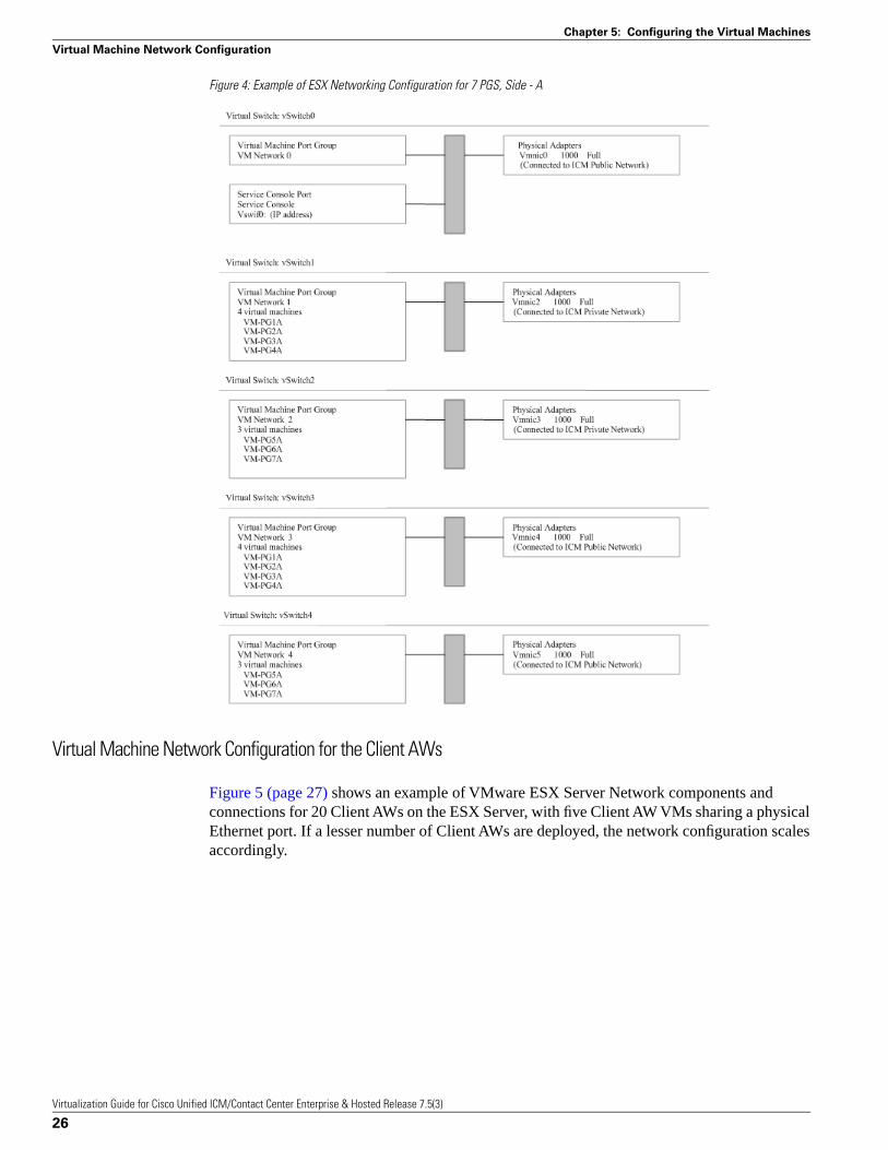
Figure 4: Example of ESX Networking Configuration for 7 PGS, Side - A
Virtual Machine Network Configuration for the Client AWs
Figure 5 (page 27) shows an example of VMware ESX Server Network components andconnections for 20 Client AWs on the ESX Server, with five Client AW VMs sharing a physicalEthernet port. If a lesser number of Client AWs are deployed, the network configuration scalesaccordingly.
Virtualization Guide for Cisco Unified ICM/Contact Center Enterprise & Hosted Release 7.5(3)
26
Chapter 5: Configuring the Virtual Machines
Virtual Machine Network Configuration

Figure 5: VMware ESX Server Network Components and Connections for the Client AWs
Figure 6 (page 28) shows an example of the ESX networking configuration for 20 Client AWs,as seen from the VMware Infrastructure Client.
Virtualization Guide for Cisco Unified ICM/Contact Center Enterprise & Hosted Release 7.5(3)
27
Chapter 5: Configuring the Virtual Machines
Virtual Machine Network Configuration

Figure 6: Example of ESX Networking Configuration for 20 Client AWs
Virtual Machine Network Configuration for a Mix of PGs and Client AWs
Figure 7 (page 29) shows an example of VMware ESX Server network components andconnections for two PG VMs and six Client AW VMs.
Virtualization Guide for Cisco Unified ICM/Contact Center Enterprise & Hosted Release 7.5(3)
28
Chapter 5: Configuring the Virtual Machines
Virtual Machine Network Configuration

Figure 7: VMware ESX Server Network Components and Connections for 2 PGs and 6 Client AWs
In the above example:
• There are two PGs and each PG has two Ethernet connections, one for the private networkand one for the public network.
• There are six Client AW VMs, and each Client AW VM is connected to the public network.
• There are five virtual switches:
– vSwitch0 – used for the ESX Service Console.
– vSwitch1 – used for the private network connected to two PGs.
– vSwitch2 – spare, not used.
– vSwitch3 – used for the public network connected to two PGs.
– vSwitch4 – used for the public network connected to six Client AWs.
Figure 8 (page 30) shows an example of the ESX networking configuration for two PGs andsix Client AWs, as seen from the VMware Infrastructure Client.
Virtualization Guide for Cisco Unified ICM/Contact Center Enterprise & Hosted Release 7.5(3)
29
Chapter 5: Configuring the Virtual Machines
Virtual Machine Network Configuration

Figure 8: Example of ESX Networking Configuration for 2 PGs and 6 Client AWs
Installing the VMware Tools
The VMware Tools must be installed on each of the VMs and all of the VMware Toolsdefault settings should be used.
To install or upgrade VMware Tools on the VM, refer to the VMware Quick Start Guide,available at: www.vmware.com/support (http://pubs.vmware.com/vi301/quick_start/wwhelp/wwhimpl/common/html/wwhelp.htm?context=quick_start&file=vi_quick_start_manage.5.1.html).(Refer to the section: "Creating and Managing VMware Infrastructure Components, InstallingGuest Operating Systems: VMware Tools".)
Virtualization Guide for Cisco Unified ICM/Contact Center Enterprise & Hosted Release 7.5(3)
30
Chapter 5: Configuring the Virtual Machines
Installing the VMware Tools

Installing ICM Components on a Virtual Machine
You can install the ICM components (PGs and Client AWs) after the configuration of the VMs.The installation of these ICM components on a VM is the same as the installation of thesecomponents on real physical hardware.
Refer to the ICM documentation available at: www.cisco.com/support (http://www.cisco.com/en/US/products/sw/custcosw/ps1001/prod_installation_guides_list.html), for the steps to installICM components. You can install the supported Virus Scan software, the Cisco Security Agent(CSA), or any other software in the same way as it is installed on physical hardware.
Remote Control of the Virtual Machines
For administrative tasks, you can use either Windows Remote Desktop or the VMwareInfrastructure Client for remote control. The contact center supervisor can access the ClientAW VM using Windows Remote Desktop.
System Monitoring
VMware provides a set of system monitoring tools for the ESX platform and the VMs. Thesetools are accessible through the VMware Infrastructure Client or through VirtualCenter.
You can use Windows Performance Monitor to monitor the performance of the VMs. Be awarethat the CPU counters may not reflect the physical CPU usage since the Windows OperatingSystem has no direct access to the physical CPU.
You can use ICM Serviceability Tools and ICM reports to monitor the operation and performanceof the ICM system.
The ESX Server and the virtual machines must operate within the limit of the following ESXperformance counters. If you find that the CPU or RAM usage exceeds the following guidelines,you need to allocate more CPU or RAM resources to this virtual machine in order to avoidinterruption due to resource contention.
• CPU usage (average) should not exceed 60% for the ESX Server and for each of the individualprocessors.
• Memory usage (average) should not exceed 80% for the ESX Server and for each of theVMs.
Virtualization Guide for Cisco Unified ICM/Contact Center Enterprise & Hosted Release 7.5(3)
31
Chapter 5: Configuring the Virtual Machines
Installing ICM Components on a Virtual Machine

Virtualization Guide for Cisco Unified ICM/Contact Center Enterprise & Hosted Release 7.5(3)
32
Chapter 5: Configuring the Virtual Machines
System Monitoring
System Backup and MigrationUse the following techniques to back up a Virtual Machine:
• You can backup and restore VMs by copying the VM folders. This technique allows you torestore your system from disastrous situations, such as a corrupted/bad hard drive.
Note: It is recommended that you back up the VMs, after the ICM application is successfullyinstalled, configured, and tested. These VMs can later be restored from the folder backup.
This chapter contains the following topics:
• Backup and Restore Technique, page 33• Migrating the VMs to another Host by Cloning, page 34
Backup and Restore Technique
Backup by Copying the Virtual Machine Folder
The backup procedure requires a Windows 2003 file server as the backup system, and theWinSCP tool (the WinSCP tool is available for download on the Internet).
Follow these steps to backup a VM, by copying the VM folder:
Step 1 Stop the ICM services and close all the applications on this VM.
Step 2 Shutdown the VM.
Step 3 Use WinSCP to copy the VM folder from the ESX host machine to the Windows 2003 fileserver. (As an example, the VM folder can be in the ESX host //root/vmfs/ folder.)
Virtualization Guide for Cisco Unified ICM/Contact Center Enterprise & Hosted Release 7.5(3)
33
Chapter 6
Step 4 Power on the VM.
Step 5 Restart the ICM services and applications
Restore VM from a VM Backup Folder
Follow these steps to restore a VM from a VM folder backup:
Step 1 If the VM is powered on, stop the ICM services and close all the applications on this VM.
Step 2 Shutdown the VM.
Step 3 Use WinSCP to copy the VM folder from the Windows 2003 file server to the ESX host machinefolder, to the same location from which it was copied for the backup.
Step 4 Power on the VM.
Step 5 You may need to rejoin the Domain if you are unable to log into the Domain and the DomainController is unable to recognize the restored VM.
Step 6 Restart the ICM services and applications.
Migrating the VMs to another Host by Cloning
You can migrate the VMs from one ESX host to another, using the VMware Cloning technique.The Cloning technique does not delete the original VMs. You can delete the original VMs afteryou have migrated the VMs and tested them successfully on the new ESX host. For generalVM cloning steps, refer to the section "Cloning Virtual Machines" in the VMware documentBasic System Administration.
Virtualization Guide for Cisco Unified ICM/Contact Center Enterprise & Hosted Release 7.5(3)
34
Chapter 6: System Backup and Migration
Migrating the VMs to another Host by Cloning

Unsupported Features and ConfigurationsThis chapter contains the following topics:
• VMware Features, page 35• Unified CCE Components/Features on Virtual Machine, page 36• SAN, iSCSI, and NAS, page 36
VMware Features
Cisco has not evaluated nor tested the following VMware tools or features. Therefore, they arenot supported on the Unified ICM/CCE virtualized solution.
Table 8: Unsupported VMware Features
DescriptionTools/Features
Provision VMs instantaneously and move the VMs betweenphysical servers.
VirtualCenter Virtual machine provisioning and migration
Manage multiple simultaneous conversions to VMs.VirtualCenter Integrated Physical to VM conversion
Converts physical machines, virtual machine formats suchas Microsoft VirtualServer or VirtualPC, backup images ofphysical machines such as Symantec Backup ExecLiveStateRecovery, Ghost 9, VMware Consolidated backupimages to running virtual machines.
Migrates running virtual machines from one physical serverto another with VMware VMotion.
VirtualCenter Live migration of VMs
Migrates running virtual machine disks from one storagearray to another with VMware Storage VMotion.
VirtualCenter Live migration of VM disk
Allows you to move a running virtual machine from onephysical ESX Server to another
VMotion
Virtualization Guide for Cisco Unified ICM/Contact Center Enterprise & Hosted Release 7.5(3)
35
Chapter 7

DescriptionTools/Features
Tool that allows physical-to-virtual migrationPlatespin’s PowerP2V
Tool that allows ESX Server sizing by gathering the detailedutilization and trending information of your physical server.
Platespin’s PowerRecon
VMware High Availability solution. This is not applicableto Unified ICM/CCE since it already has a fault-tolerancesolution.
VMware HA
A cluster file system that leverages shared storage to allowmultiple instances of ESX Server to read and write to thesame storage
Shared storage in VMware VMFS with multiple ESXServers
Unified CCE Components/Features on Virtual Machine
Cisco has only evaluated and tested the Client AW and specific PGs on the virtualized platform.No other Unified ICM/CCE components or features are supported on the Unified ICM/CCEvirtualized platform. This means that components such as the following are not supported:
• CallRouter
• Logger
• AW Distributor
• HDS
• WebView
• Outbound
• Mobile Agent
• Unified System CCE
• CAD server
SAN, iSCSI, and NAS
Cisco has neither evaluated nor tested the SAN (Storage Area Network), iSCSI, or NAS (NetworkAttached Storage) in the virtualized environment for the Unified ICM/CCE application.Therefore, they are not supported in the Unified ICM/CCE virtualized environment.
Virtualization Guide for Cisco Unified ICM/Contact Center Enterprise & Hosted Release 7.5(3)
36
Chapter 7: Unsupported Features and Configurations
Unified CCE Components/Features on Virtual Machine

Index
Backup and Restore Technique....33
Copying VM Folder....33
CCE Components....36
Cloning....34
Configuration Consideration....7
For Agent Peripheral....8
For AW Clients....10
For CCE gateway....9
TDM ACD PG....10
Configuration Consideration for PGs
For PGs....8
Configuring ESX Server....13
Configuring ESX Hardware....13
deploying IPCC Agent PGs....8
Deployment Configuration Considerations....7
ESX CPU Affinity....19
ESX CPU Affinity Setting....20
ESX kernel....19
ESX networking configuration....23, 25
Insatlling VMware VirtualCenter....16
Installing ESX Software....14
Installing ICM Components on a VM....31
Installing the VMware Tools....30
iSCSI....36
Peripheral Gateways....5
Remote Control of VMs....31
SAN....36
System backup and Migration....33
System Monitoring....31
Virtualization Management Tools....11
Virtualization Solution....5
Virtual Machine Network Configurations....22, 24
For AW Clients....26
For PGs....22, 24
Virtual Machine Resource management DefaultSettings....20
Virtual Machines....17
Configuration....17
Properties....17
VM Properties for the AW Client....18
VM Resource Management Consideration....19
Virtualization Guide for Cisco Unified ICM/Contact Center Enterprise & Hosted Release 7.5(3)
Index 37
Index