TSF EXPERIMENT FOR COMPARISON OF HlGH REYNOLDS …
9
TSF EXPERIMENT FOR COMPARISON OF HlGH REYNOLDS NUMBER TURBULENCE IN BOTH HE I AND HE II: FIRST RESULTS B. Rousset, C. Baudet, M. Bon Mardion, B. Castaing, D. Communal et al. Citation: AIP Conf. Proc. 985, 633 (2008); doi: 10.1063/1.2908608 View online: http://dx.doi.org/10.1063/1.2908608 View Table of Contents: http://proceedings.aip.org/dbt/dbt.jsp?KEY=APCPCS&Volume=985&Issue=1 Published by the American Institute of Physics. Additional information on AIP Conf. Proc. Journal Homepage: http://proceedings.aip.org/ Journal Information: http://proceedings.aip.org/about/about_the_proceedings Top downloads: http://proceedings.aip.org/dbt/most_downloaded.jsp?KEY=APCPCS Information for Authors: http://proceedings.aip.org/authors/information_for_authors Downloaded 17 Jun 2013 to 193.48.255.141. This article is copyrighted as indicated in the abstract. Reuse of AIP content is subject to the terms at: http://proceedings.aip.org/about/rights_permissions
Transcript of TSF EXPERIMENT FOR COMPARISON OF HlGH REYNOLDS …
TSF EXPERIMENT FOR COMPARISON OF HlGH REYNOLDS NUMBERTURBULENCE IN BOTH HE I AND HE II: FIRST RESULTSB. Rousset, C. Baudet, M. Bon Mardion, B. Castaing, D. Communal et al. Citation: AIP Conf. Proc. 985, 633 (2008); doi: 10.1063/1.2908608 View online: http://dx.doi.org/10.1063/1.2908608 View Table of Contents: http://proceedings.aip.org/dbt/dbt.jsp?KEY=APCPCS&Volume=985&Issue=1 Published by the American Institute of Physics. Additional information on AIP Conf. Proc.Journal Homepage: http://proceedings.aip.org/ Journal Information: http://proceedings.aip.org/about/about_the_proceedings Top downloads: http://proceedings.aip.org/dbt/most_downloaded.jsp?KEY=APCPCS Information for Authors: http://proceedings.aip.org/authors/information_for_authors
Downloaded 17 Jun 2013 to 193.48.255.141. This article is copyrighted as indicated in the abstract. Reuse of AIP content is subject to the terms at: http://proceedings.aip.org/about/rights_permissions
TSF EXPERIMENT FOR COMPARISON OF fflGH REYNOLDS NUMBER TURBULENCE IN BOTH HE I AND HE II: FIRST RESULTS
B. Rousset\ C. Baudet^, M. Bon Mardion\ B. Castaing^, D. Communal^ F. Daviaud"*, P. Diribame"*, B. DubruUe"*, A. Forgeas\ Y. Gagne^, A. Girard\ B. Hebral^ P.-E. Rochet P. Roussel\ P. Thibault^
^DSM/DRFMC/SBT, CEA, F-38054 Grenoble Cedex 9, France
^CNRS-UJF-INPG/LEGI, F-38041 Grenoble Cedex 09, France
^ENS Lyon, UMR 5672, F-69364 Lyon Cedex 07,France
"•DSM/DRECAM/SPEC, C N R S U R A 2464, CEA Saclay F-91191 Gif sur Yvette Cedex, France
^CNRS-UJF/lnstitut Neel, BP 166 38042 Grenoble Cedex 09, France
ABSTRACT
Superfluid turbulence (TSF) project uses liquid helium for the fundamental study of turbulent phenomena behind a passive grid and is able to work both in Hel and in Hell. The helium flow is generated by a cold Barber and Nichols circulating pump, whereas helium flow temperature is kept constant by means of a heat exchanger immersed in a saturated bath. This experiment takes profit of the CEA Grenoble refrigerator (nominal capacity of 400 Watt at 1.8 K) to remove the heat due to pressure losses in this high Reynolds number experiment. In order to resolve the Kolmogorov scale associated with high Re flow, local instrumentation (e.g. sub-micrometer anemometer) was developed. The difficulties encountered with this local and fragile instrumentation in a quasi industrial environment are discussed and the adopted solutions are also described. Finally, first results (permanent mass flow rate of a few hundreds g/s) obtained both in the two phases of helium are presented.
CP985, Advances in Cryogenic Engineering: Transactions of the Cryogenic Engineering Conference—CEC, Vol. 53, edited by J. G. Weisend II
O 2008 American Institute of Physics 978-0-7354-0504-2/08/$23.00
633
Downloaded 17 Jun 2013 to 193.48.255.141. This article is copyrighted as indicated in the abstract. Reuse of AIP content is subject to the terms at: http://proceedings.aip.org/about/rights_permissions
KEYWORDS: turbulence, superfluid, high Re PACS: 07.20.Mc
INTRODUCTION
The benefits of helium to explore High Reynolds and Rayleigh numbers Turbulence has already been emphasized for years. In thermal convection for example, D.C. Threlfall [1] in the years 1970, then A. Libchaber in Chicago [2], showed that a single helium cell can span many decades of very high Rayleigh numbers. The geometry adopted for TSF experiment is an isothermal grid flow with a lower turbulence intensity as compared with axisymetric turbulent jet flows. It garanties a good fulfilment of the Taylor hypothesis as well as a good homogeneity and isotropy of the turbulence. One objective is to reach RX numbers (Re based on Taylor's scale) in helium as high as 300. This value obtained for a grid turbulence will be comparable with the most important laboratory apparatus, under carefully controled conditions. Furthermore, this experiment will enable to work with liquid helium both above and below the superfluid transition at T;̂ ~ 2.17K (respectively He I and He II). Whereas He I presents classical (Navier-Stokes) turbulence behaviour. He II turbulence is interesting because of the peculiar nature of the energy dissipation process, occurring for example by quantum vortices reconnection. Study of both fluids in the same test loop can then be used to constrain or validate several open problems in turbulence, connected with small-scale processes.
EXPERIMENTAL FACILITY AND DESCRIPTION OF THE MAIN COMPONENTS
Experimental facility description
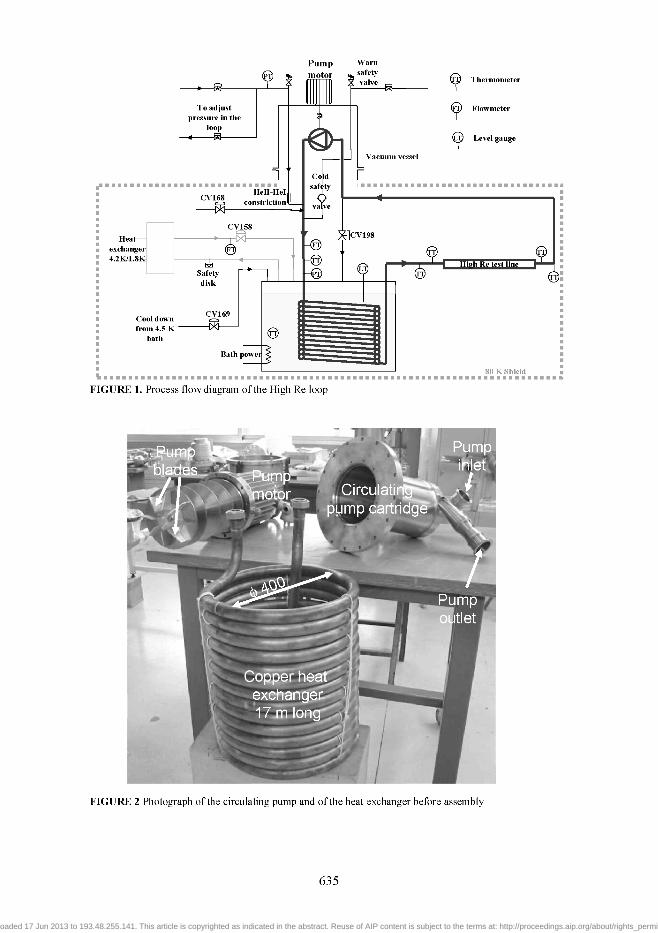
As the preliminary design of the test loop has been already presented elsewhere [4], the process flow diagram (figure 1) will be shortly discussed. From the outlet of the circulating pump to its inlet, the closed circuit includes: a connection to room temperature helium circuit for pressurization, a connection to cold safety valve with discharge circuit downstream, a venturi flowmeter equipped with home-made cold differential pressure sensor [5], a coiled shape heat exchanger immersed inside the saturated bath, and finally the test line equipped with dedicated sensors. A sub-micronic superconducting hot wire anemometer is installed for measurements in He I while a miniature second sound attenuation probe [6] is dedicated to superfluid measurements. Finally, acoustic scattering by vorticity is expected to work both in He I and in He II. To adjust the temperature to the required value, the saturated pressure bath is controlled via the pumping unit of the refrigerator.
Main components of the loop
As the test loop has to run both in He I and in He II, direct helium pipe connections to room temperature have to be avoided, and we resort to the so-called "Claudet bath" technique used. The CV168 valve is used to fill in the loop, with helium at T;̂ and 1 bar while the CV198 valve permits to empty the loop. A special circuit connected to helium gas at room temperature stabilizes the pressure inside the line at a value between
634
Downloaded 17 Jun 2013 to 193.48.255.141. This article is copyrighted as indicated in the abstract. Reuse of AIP content is subject to the terms at: http://proceedings.aip.org/about/rights_permissions
Pump Warn motor % safety
valve X) Thermometer
FIGURE 1. Process flow diagram of the High Re loop
FIGURE 2 Photograph of the circulating pump and of the heat exchanger before assembly
635
Downloaded 17 Jun 2013 to 193.48.255.141. This article is copyrighted as indicated in the abstract. Reuse of AIP content is subject to the terms at: http://proceedings.aip.org/about/rights_permissions
1 and 5 bars. This circuit includes a small ID. pipe calculated to minimize the heat load due to He II critical heat flux. For the same reason, the safety device must include a cold safety valve to reduce heat load falling in the sub-cooled He II. The circulating pump used was a Barber and Nichols one, loaned by CERN and designed for He I flow. Characteristics in such conditions were explored at CEASaclay [7] but it was never established in superfluid where additional load due to critical heat flux arises. A rough estimation based on the internal geometry of the pump leads to 30 Watt of additional load in the 1.6 - 2.1 K range. As this pump must be run vertical with the motor located at the top and at room temperature, it has been installed in the upper part of the cryostat. Finally, the heat exchanger immersed in the saturated bath consists of a simple 17 m long copper coiled pipe of 30 mm in ID. which was calculated as the best single channel compromise between heat exchange, pressure losses and longitudinal thermal short-circuit in subcooled Hell (see figure 2).
Working procedure, first tests and improvements
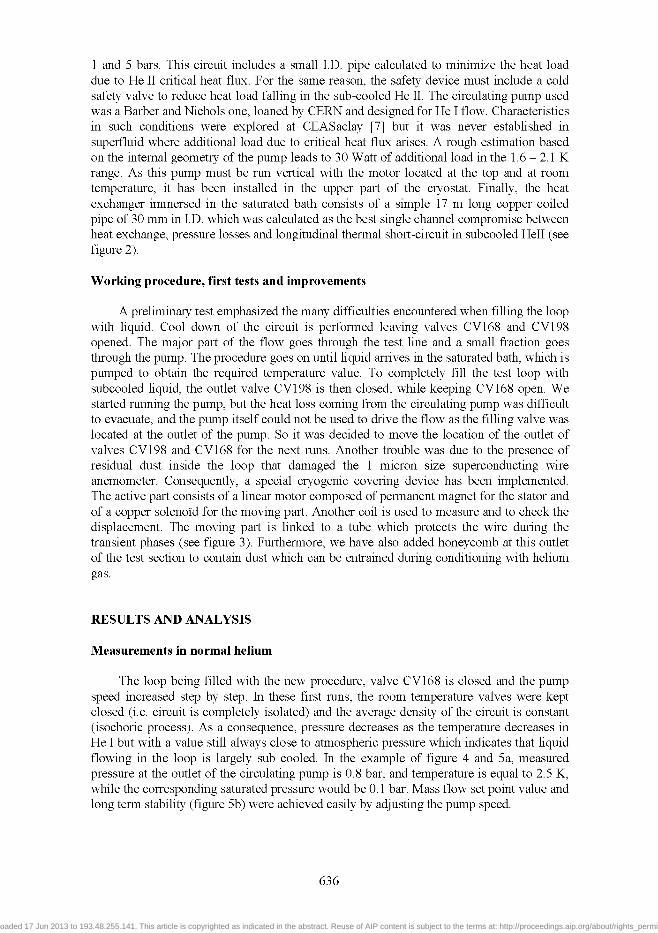
A preliminary test emphasized the many difficulties encountered when filling the loop with liquid. Cool down of the circuit is performed leaving valves CV168 and CV198 opened. The major part of the flow goes through the test line and a small fraction goes through the pump. The procedure goes on until liquid arrives in the saturated bath, which is pumped to obtain the required temperature value. To completely fill the test loop with subcooled liquid, the outlet valve CV198 is then closed, while keeping CV168 open. We started running the pump, but the heat loss coming from the circulating pump was difficult to evacuate, and the pump itself could not be used to drive the flow as the filling valve was located at the outlet of the pump. So it was decided to move the location of the outlet of valves CV198 and CV168 for the next runs. Another trouble was due to the presence of residual dust inside the loop that damaged the 1 micron size superconducting wire anemometer. Consequently, a special cryogenic covering device has been implemented. The active part consists of a linear motor composed of permanent magnet for the stator and of a copper solenoid for the moving part. Another coil is used to measure and to check the displacement. The moving part is linked to a tube which protects the wire during the transient phases (see figure 3). Furthermore, we have also added honeycomb at this outlet of the test section to contain dust which can be entrained during conditioning with helium gas.
RESULTS AND ANALYSIS
Measurements in normal Iielium
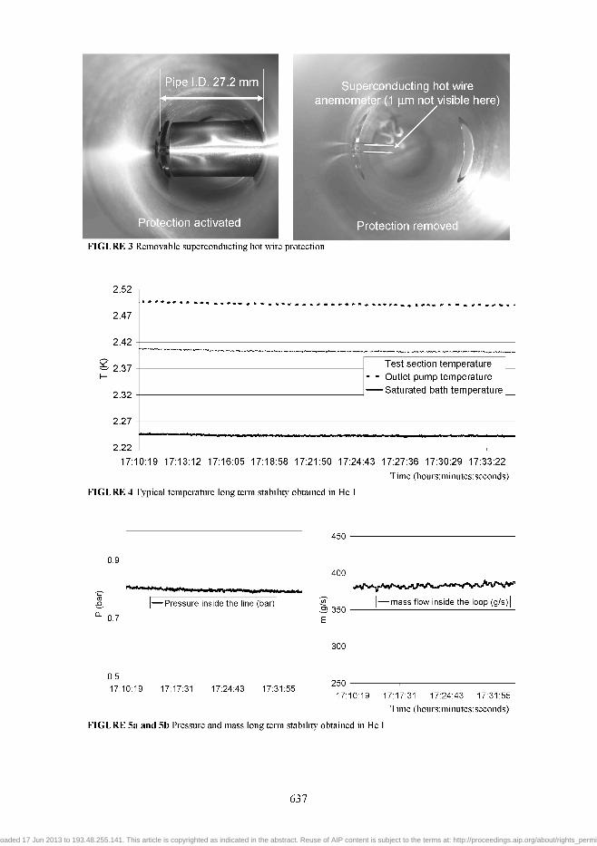
The loop being filled with the new procedure, valve CV168 is closed and the pump speed increased step by step. In these first runs, the room temperature valves were kept closed (i.e. circuit is completely isolated) and the average density of the circuit is constant (isochoric process). As a consequence, pressure decreases as the temperature decreases in He I but with a value still always close to atmospheric pressure which indicates that liquid flowing in the loop is largely sub cooled. In the example of figure 4 and 5a, measured pressure at the outlet of the circulating pump is 0.8 bar, and temperature is equal to 2.5 K, while the corresponding saturated pressure would be 0.1 bar. Mass flow set point value and long term stability (figure 5b) were achieved easily by adjusting the pump speed.
636
Downloaded 17 Jun 2013 to 193.48.255.141. This article is copyrighted as indicated in the abstract. Reuse of AIP content is subject to the terms at: http://proceedings.aip.org/about/rights_permissions
%
Pipe I.D. 27.2 mm
' i M ^ ^ ^ M M H ^ r i
X
g • r
PrNection activated
FIGURE 3 Removable superconducting hot wire protection
2.52
2.47
2.42
2.37
2.32
2.27
2.22
Test section temperature - - Outlet pump temperature
Saturated bath temperature
•M**WM«M«wwAMiHar f«
17:10:19 17:13:12 17:16:05 17:18:58 17:21:50 17:24:43 17:27:36 17:30:29 17:33:22
Time (hours:minutes:seconds)
FIGURE 4 Typical temperature long term stability obtained in He I
0.9
0.7
•Pressure inside the line (bar)
0.5
17:10:19 17:17:31 17:24:43 17:31:55
450
400
S 350
300
250
•mass flow inside the loop (g/s)
17:10:19 17:17:31 17:24:43 17:31:55
Time (hours:minutes:seconds)
FIGURE 5a and 5b Pressure and mass long term stability obtained in He I
637
Downloaded 17 Jun 2013 to 193.48.255.141. This article is copyrighted as indicated in the abstract. Reuse of AIP content is subject to the terms at: http://proceedings.aip.org/about/rights_permissions
Measurements in superfluid helium
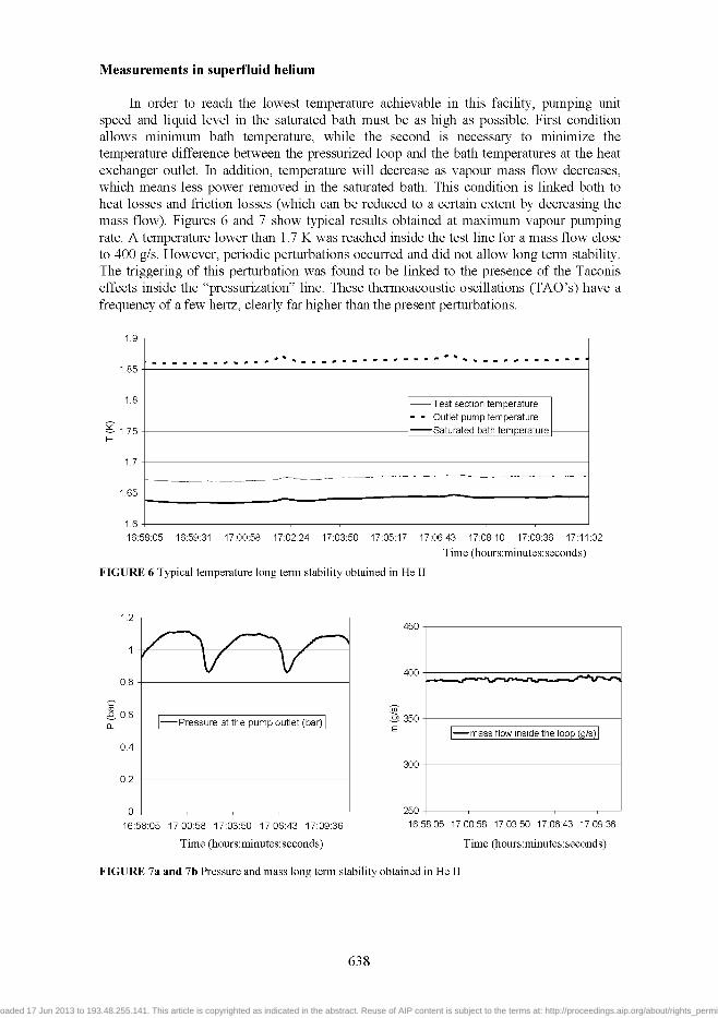
In order to reach the lowest temperature achievable in this facility, pumping unit speed and liquid level in the saturated bath must be as high as possible. First condition allows minimum bath temperature, while the second is necessary to minimize the temperature difference between the pressurized loop and the bath temperatures at the heat exchanger outlet. In addition, temperature will decrease as vapour mass flow decreases, which means less power removed in the saturated bath. This condition is linked both to heat losses and friction losses (which can be reduced to a certain extent by decreasing the mass flow). Figures 6 and 7 show typical results obtained at maximum vapour pumping rate. A temperature lower than 1.7 K was reached inside the test line for a mass flow close to 400 g/s. However, periodic perturbations occurred and did not allow long term stability. The triggering of this perturbation was found to be linked to the presence of the Taconis effects inside the "pressurization" line. These thermoacoustic oscillations (TAO's) have a frequency of a few hertz, clearly far higher than the present perturbations.
1.9-
1.85-
1.75-
1.7
1.65-
- Test section temperature Outlet pump temperature
-Saturated bath temperature -
1.6 ^ , , , , , , , , 16:58:05 16:59:31 17:00:58 17:02:24 17:03:50 17:05:17 17:06:43 17:08:10 17:09:36 17:11:02
Time (hours:minutes:seconds)
FIGURE 6 Typical temperature long term stability obtained in He II
16:58:05 17:00:58 17:03:50 17:06:43 17:09:36
Time (hours:minutes:seconds)
450
400
350
300
250
-mass flow inside the loop (g/s)
16:58:05 17:00:58 17:03:50 17:06:43 17:09:36
Time (hours:minutes:seconds)
FIGURE 7a and 7b Pressure and mass long term stability obtained in He II
638
Downloaded 17 Jun 2013 to 193.48.255.141. This article is copyrighted as indicated in the abstract. Reuse of AIP content is subject to the terms at: http://proceedings.aip.org/about/rights_permissions
However, heat losses due to TAO's may evaporate a fraction of liquid inside the "pressurization" line until change inside this line kills the TAO's. Then, heat losses disappeared, new temperature gradient arises along the line and vapour condensates again until TAO's reappears and so on. This could explain the observed discrepancy of the time constants between TAO's and thermohydraulic perturbations inside the loop.
Summary of data
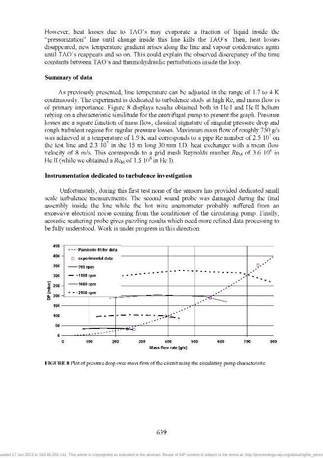
As previously presented, line temperature can be adjusted in the range of 1.7 to 4 K continuously. The experiment is dedicated to turbulence study at high Re, and mass flow is of primary importance. Figure 8 displays results obtained both in He I and He II helium relying on a characteristic similitude for the centrifugal pump to present the graph. Pressure losses are a square function of mass flow, classical signature of singular pressure drop and rough turbulent regime for regular pressure losses. Maximum mass flow of roughly 750 g/s was achieved at a temperature of 1.9 K and corresponds to a pipe Re number of 2.5 lO' on the test line and 2.3 lO' in the 15 m long 30 mm I.D. heat exchanger with a mean flow velocity of 8 m/s. This corresponds to a grid mesh Reynolds number Reu of 3.6 10"̂ in He II (while we obtained a RQM of 1.5 10"̂ in He I).
Instrumentation dedicated to turbulence investigation
Unfortunately, during this first test none of the sensors has provided dedicated small scale turbulence measurements. The second sound probe was damaged during the final assembly inside the line while the hot wire anemometer probably suffered from an excessive electrical noise coming from the conditioner of the circulating pump. Finally, acoustic scattering probe gives puzzling results which need more refined data processing to be fully understood. Work is under progress in this direction.
400
350
300
1 250 E. 0. 200 a
0
- - - Parabolic fit for data
O experimental data
700 rpm
— -1190 rpm
1660 rpm
- - 2100 rpm
. . . . _ - • '
. . - • '
' ^ .
^ »
, ' '
,' '
l ^ r ' '
100 200 300 400 500
Mass flow rate (g/s)
600 700 800
FIGURE 8 Plot of pressure drop over mass flow of the circuit using the circulating pump characteristic
639
Downloaded 17 Jun 2013 to 193.48.255.141. This article is copyrighted as indicated in the abstract. Reuse of AIP content is subject to the terms at: http://proceedings.aip.org/about/rights_permissions
CONCLUSION
This first series of runs permits to test the experimental loop behaviour and to define the available range of temperature and mass flow. Simple coiled pipe heat exchanger was found efficient enough to achieve a difference in temperature lower than 0.1 K even at 1.6 K. Pipe Re numbers as high as 2 lO' were obtained in steady state. A removable not intrusive (when removed) hot wire protection working at cryogenic temperature was designed, built and tested with success. Nevertheless some improvements are still needed to improve stability in the superfluid domain and to develop reliable turbulence instrumentation.
REFERENCES
1. Threlfall D.C., "Free convection in low temperature gaseous helium", J. of Fluid Mech.('^915) vol 67 17-28
2. Wu X.Z. and Libchaber A., "Scaling relations in thermal turbulence : the aspect-ratio dependence ", Phys. Rev. A. (1992), vol 45 842
3. Castaing B. et al., "Hot wire anemometer operating at cryogenic temperatures". Review of Scientific Instruments (1992) vol 63 4167-4173
4. Rousset B. et al, "Comparison between Normal and Superfluid Turbulence Behind a Passive Grid : Experimental Facility ", to be published in the proceeding of the ICEC conference (2006)
5. Thibault P. et al., "On the design of capacitive sensors using flexible electrodes for multipurpose measurements". Review of Scientific Instruments (2007) vol 78
6. Roche P.-E. et al., "Vortex density spectrum of quantum turbulence ", EPL (2007) vol 7 66002 7. Mayri C. et al, "Test of a high mass flowrate pump in He I", ICEC 19 (2002) 75-78
640
Downloaded 17 Jun 2013 to 193.48.255.141. This article is copyrighted as indicated in the abstract. Reuse of AIP content is subject to the terms at: http://proceedings.aip.org/about/rights_permissions