Traditional Thermostatic Shower Valve 50014CP & · PDF fileTraditional Thermostatic Shower...
16
Traditional Thermostatic Shower Valve 50014CP & 50015CP Installation and Maintenance Instructions In this procedure document we have endeavoured to make the information as accurate as possible. We cannot accept any responsibility should it be found that in any respect the information is inaccurate or incomplete or becomes so as a result of further developments or otherwise. Intatec Ltd Airfield Industrial Estate Hixon Staffordshire ST18 0PF Tel: 01889 272 180 Fax: 01889 272 181 email: [email protected] web: www.intatec.co.uk © Intatec Ltd. 2014
Transcript of Traditional Thermostatic Shower Valve 50014CP & · PDF fileTraditional Thermostatic Shower...
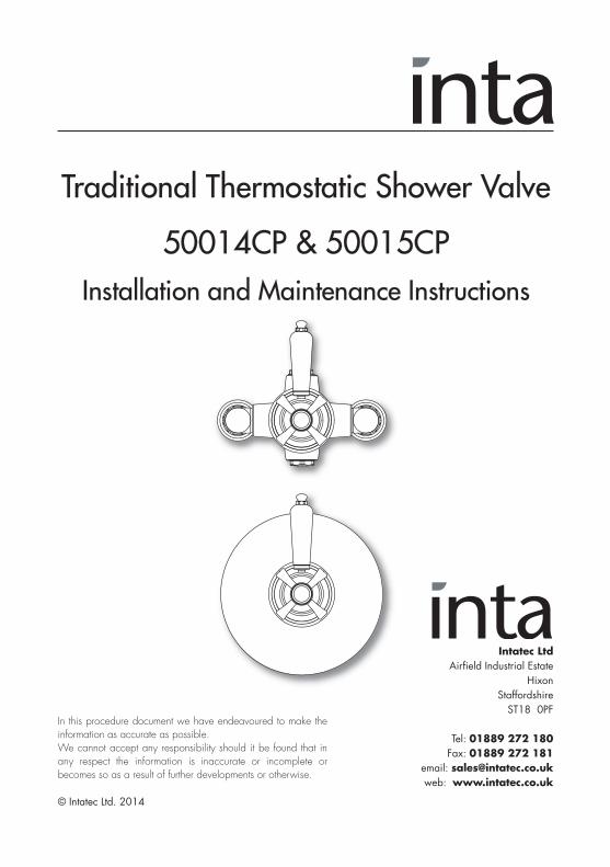
Traditional Thermostatic Shower Valve
50014CP & 50015CPInstallation and Maintenance Instructions
In this procedure document we have endeavoured to make theinformation as accurate as possible.We cannot accept any responsibility should it be found that inany respect the information is inaccurate or incomplete orbecomes so as a result of further developments or otherwise.
Intatec LtdAirfield Industrial Estate
HixonStaffordshireST18 0PF
Tel: 01889 272 180Fax: 01889 272 181
email: [email protected]: www.intatec.co.uk
© Intatec Ltd. 2014
© Intatec Ltd 2014 1
Introduction This installation guide has been produced for the Traditional concealed and exposed thermostatic dual control shower mixing valves. These instructions cover the installation, operation and maintenance. Please read the enclosed instructions before commencing the installation of this product, please note;
We recommend that the installation of any Inta product is carried out by an approved installer.
The installation must be carried out strictly in accordance with the Water Supply (Water Fitting) Regulations 1999 and any local authority regulations.
If in doubt we recommend that you contact WRAS - Water Regulations Advisory Scheme on Tel: 0333 207 903, your local water authority - details available on the WRAS website or the Chartered Institute of Plumbing and Heating Engineers on Tel: 01708 472 791.
All products MUST be re-commissioned to suit site conditions to ensure optimum performance levels of the product are obtained.
SafetyThis thermostatic shower must be installed and commissioned correctly to ensure that water is supplied at a safe temperature to suit the users.
43˚C is the maximum mixed water temperature from a shower mixer. The maximum temperature takes account of the allowable tolerances inherent in thermostatic shower mixers and temperature losses.
It is not a safe washing Temperature for adults or children.
The British Burns Association recommends 37 to 37.5˚C as a comfortable washing temperature for children. In premises covered by the Care Standard Act 2000, the maximum mixed water outlet temperature is 43˚C.
ProductsTraditional Exposed Thermostatic Dual Control Shower 50014CP
Traditional Concealed Thermostatic Dual Control Shower 50015CP
Check Content Before commencing remove all components from packaging and check each component with the contents list.
Ensure all parts are present, before discarding any packaging. If any parts are missing, do not attempt to install your Inta shower valve until the missing parts have been obtained.
© Intatec Ltd 2014 2
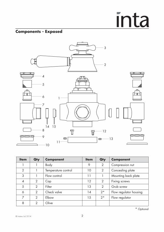
Components - Exposed
Item Qty Component Item Qty Component
1 1 Body 9 2 Compression nut
2 1 Temperature control 10 2 Concealing plate
3 1 Flow control 11 1 Mounting back plate
4 2 Cap 12 2 Fixing screws
5 2 Filter 13 2 Grub screw
6 2 Check valve 14 2* Flow regulator housing
7 2 Elbow 15 2* Flow regulator
8 2 Olive
* Optional
1
4
5
6
7
8
1110
9
12
13
2
3
14 15
© Intatec Ltd 2014 3
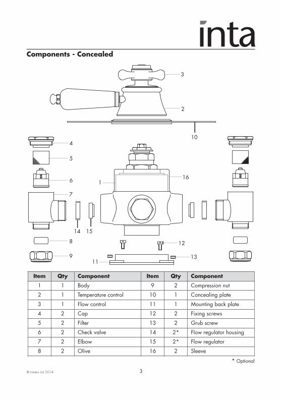
Components - Concealed
Item Qty Component Item Qty Component
1 1 Body 9 2 Compression nut
2 1 Temperature control 10 1 Concealing plate
3 1 Flow control 11 1 Mounting back plate
4 2 Cap 12 2 Fixing screws
5 2 Filter 13 2 Grub screw
6 2 Check valve 14 2* Flow regulator housing
7 2 Elbow 15 2* Flow regulator
8 2 Olive 16 2 Sleeve
* Optional
1
4
5
6
7
8
119
12
13
2
3
14 15
10
16
© Intatec Ltd 2014 4
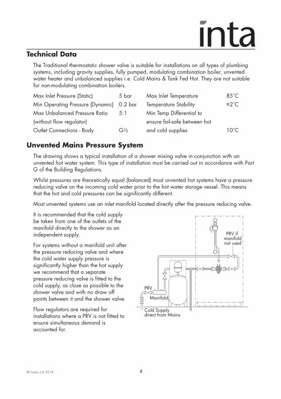
Technical Data The Traditional thermostatic shower valve is suitable for installations on all types of plumbing systems, including gravity supplies, fully pumped, modulating combination boiler, unvented water heater and unbalanced supplies i.e. Cold Mains & Tank Fed Hot. They are not suitable for non-modulating combination boilers.
Max Inlet Pressure (Static) 5 bar Max Inlet Temperature 85˚C Min Operating Pressure (Dynamic) 0.2 bar Temperature Stability ±2˚C Max Unbalanced Pressure Ratio 5:1 Min Temp Differential to (without flow regulator) ensure fail-safe between hot Outlet Connections - Body G½ and cold supplies 10˚C Unvented Mains Pressure System The drawing shows a typical installation of a shower mixing valve in conjunction with an unvented hot water system. This type of installation must be carried out in accordance with Part G of the Building Regulations.
Whilst pressures are theoretically equal (balanced) most unvented hot systems have a pressure reducing valve on the incoming cold water prior to the hot water storage vessel. This means that the hot and cold pressures can be significantly different.
Most unvented systems use an inlet manifold located directly after the pressure reducing valve.
It is recommended that the cold supply be taken from one of the outlets of the manifold directly to the shower as an independent supply.
For systems without a manifold unit after the pressure reducing valve and where the cold water supply pressure is significantly higher than the hot supply we recommend that a separate pressure reducing valve is fitted to the cold supply, as close as possible to the shower valve and with no draw off points between it and the shower valve.
Flow regulators are required for installations where a PRV is not fitted to ensure simultaneous demand is accounted for.
PRV
Manifold
Cold Supplydirect from Mains
PRV if manifoldnot used
© Intatec Ltd 2014 5
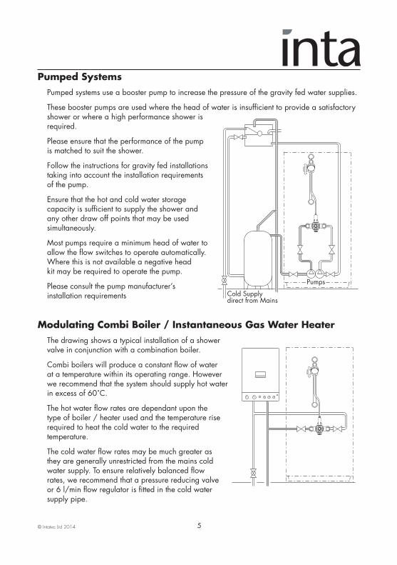
Pumped Systems Pumped systems use a booster pump to increase the pressure of the gravity fed water supplies.
These booster pumps are used where the head of water is insufficient to provide a satisfactory shower or where a high performance shower is required.
Please ensure that the performance of the pump is matched to suit the shower.
Follow the instructions for gravity fed installations taking into account the installation requirements of the pump.
Ensure that the hot and cold water storage capacity is sufficient to supply the shower and any other draw off points that may be used simultaneously.
Most pumps require a minimum head of water to allow the flow switches to operate automatically. Where this is not available a negative head kit may be required to operate the pump.
Please consult the pump manufacturer’s installation requirements
Modulating Combi Boiler / Instantaneous Gas Water Heater The drawing shows a typical installation of a shower valve in conjunction with a combination boiler.
Combi boilers will produce a constant flow of water at a temperature within its operating range. However we recommend that the system should supply hot water in excess of 60˚C.
The hot water flow rates are dependant upon the type of boiler / heater used and the temperature rise required to heat the cold water to the required temperature.
The cold water flow rates may be much greater as they are generally unrestricted from the mains cold water supply. To ensure relatively balanced flow rates, we recommend that a pressure reducing valve or 6 l/min flow regulator is fitted in the cold water supply pipe.
Cold Supplydirect from Mains
Pumps
© Intatec Ltd 2014 6
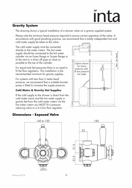
Gravity System The drawing shows a typical installation of a shower valve on a gravity supplied system.
Please note the minimum head pressure required to ensure correct operation of the valve. In accordance with good plumbing practice, we recommend that a totally independent hot and cold water supply be taken to the valve.
The cold water supply must be connected directly to the water cistern. The hot water supply should be connected to the hot water cylinder via an Essex flange or Sussex flange or to the vent or a draw off pipe as close as possible to the top of the cylinder.
For equal tank fed pressures there is no need to fit the flow regulators. This installation is the recommended minimum for gravity supplies.
For systems with less than 2 metre head pressure, we recommend that a suitable booster pump is fitted to increase the supply pressure.
Cold Mains & Gravity Hot Supplies
If the cold supply to the shower is direct from the cold water mains and the hot water supply is gravity fed from the cold water cistern via the hot water cistern you MUST fit a pressure reducing valve or a 6 l/min flow regulator.
Dimensions - Exposed Valve
G½
142 to 150 150
35
51.5
51.5
Option shownfor mains
pressure cold & low pressure
hot water
Min
. 2m
hea
d
© Intatec Ltd 2014 7
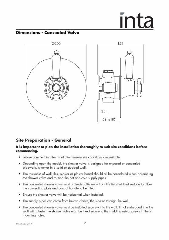
Dimensions - Concealed Valve
Site Preparation - GeneralIt is important to plan the installation thoroughly to suit site conditions before commencing.
• Before commencing the installation ensure site conditions are suitable.
• Depending upon the model, the shower valve is designed for exposed or concealed pipework, whether in a solid or studded wall.
• The thickness of wall tiles, plaster or plaster board should all be considered when positioning the shower valve and routing the hot and cold supply pipes.
• The concealed shower valve must protrude sufficiently from the finished tiled surface to allow the concealing plate and control handle to be fitted.
• Ensure the shower valve will be horizontal when installed.
• The supply pipes can come from below, above, the side or through the wall.
• The concealed shower valve must be installed securely into the wall. If not embedded into the wall with plaster the shower valve must be fixed secure to the studding using screws in the 2 mounting holes.
Ø200 152
35
58 to 80
© Intatec Ltd 2014 8
Site Preparation - General • Each shower valve is supplied with integral non return valves in the cold and hot inlet tail pieces to prevent cross contamination of the water supplies. Additional check valves may be necessary in certain circumstances to comply with the Water Regulations. With flexible hose kits, where the hand set is capable of falling within 25 mm of the top of the shower tray, additional backflow prevention devices may be required.
• Where possible, 22 mm hot and cold supplies should be used as close to the valve as possible and pipe runs should be kept to a minimum to maintain flow rates on low pressure installations.
NOTE: The inlets connections to the elbows to the shower valve are 15mm compression.
• Two 6 litre per minute flow regulators are supplied with the shower valve for when inlet pressures exceed 1.0 bar.
• The whole system should be thoroughly flushed, prior to connecting the hot and cold water supplies to the shower valve, to remove any debris that may be in the supply pipework.
• Ensure there are no joint leaks before finishing the wall.
• Isolation valves must be fitted in an accessible position to both the hot and cold supplies should the valve need to be isolated in the future for servicing.
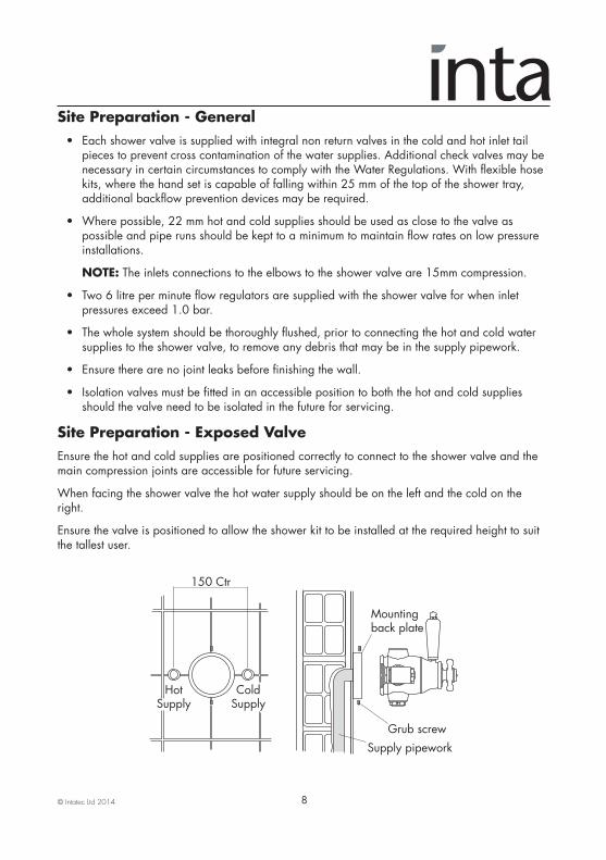
Site Preparation - Exposed ValveEnsure the hot and cold supplies are positioned correctly to connect to the shower valve and themain compression joints are accessible for future servicing.
When facing the shower valve the hot water supply should be on the left and the cold on theright.
Ensure the valve is positioned to allow the shower kit to be installed at the required height to suitthe tallest user.
150 Ctr
HotSupply
ColdSupply
Supply pipework
Mountingback plate
Grub screw
© Intatec Ltd 2014 9
Connection - Exposed ValveApply a bead of mastic to the back of the mounting back plate and fit to the wall in the requiredposition using the appropriate wall plugs to suit the wall type.
The shower valve has a bottom ½” male shower connector, suitable for use with a flexible hosekit.
Fit the valve body to the back plate and secure having first fitted any required flow regulators.
Connect the hot and cold supplies to the valve using the 15mm compression joints and check thejoints for leakage.
Apply a bead of mastic to seal the joints around the hot and cold supply pipes and the jointbetween the wall and the mounting plate/valve.
Fit the temperature and flow controllers to the valve body.
Check the function of the valve, the maximum temperature should not exceed 43˚C. If themaximum mixed water temperature exceeds this the valve must be re-calibrated to suit siteconditions.
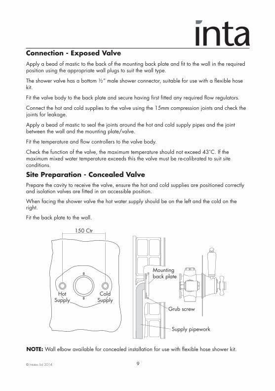
Site Preparation - Concealed ValvePrepare the cavity to receive the valve, ensure the hot and cold supplies are positioned correctlyand isolation valves are fitted in an accessible position.
When facing the shower valve the hot water supply should be on the left and the cold on theright.
Fit the back plate to the wall.
NOTE:Wall elbow available for concealed installation for use with flexible hose shower kit.
150 Ctr
HotSupply
ColdSupply
Supply pipework
Mountingback plate
Grub screw
© Intatec Ltd 2014 10
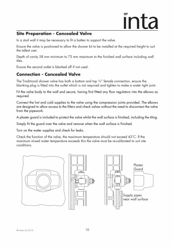
Site Preparation - Concealed ValveIn a stud wall it may be necessary to fit a batten to support the valve.
Ensure the valve is positioned to allow the shower kit to be installed at the required height to suitthe tallest user.
Depth of cavity 58 mm minimum to 73 mm maximum to the finished wall surface including walltiles.
Ensure the second outlet is blanked off if not used.
Connection - Concealed ValveThe Traditional shower valve has both a bottom and top ½” female connection, ensure theblanking plug is fitted into the outlet which is not required and tighten to make a water tight joint.
Fit the valve body to the wall and secure, having first fitted any flow regulators into the elbows asrequired.
Connect the hot and cold supplies to the valve using the compression joints provided. The elbowsare designed to allow access to the filters and check valves without the need to disconnect the valvefrom the pipework.
A plaster guard is included to protect the valve whilst the wall surface is finished, including the tiling.
Simply fit the guard over the valve and remove when the wall surface is finished.
Turn on the water supplies and check for leaks.
Check the function of the valve, the maximum temperature should not exceed 43˚C. If themaximum mixed water temperature exceeds this the valve must be re-calibrated to suit siteconditions.
PlasterGuard
Supply pipesnear wall surface

© Intatec Ltd 2014 11
Concealed Valve - Fitting the Concealing PlateOnce the valve has been installed, all the connections have been checked for leakage and thesurface of the wall has been finished the concealing plate can be fitted.
It may be necessary to lubricate the seal in the centre of the concealing plate to ease assembly ontothe valve body.
Apply a bead of mastic to the outer edge, on the back of the concealing plate and slide the plateover the valve body and press firmly to the wall.
Screw
TemperatureControl
Indice
FlowControl
Nut
© Intatec Ltd 2014 12
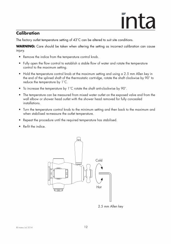
CalibrationThe factory outlet temperature setting of 43˚C can be altered to suit site conditions.
WARNING: Care should be taken when altering the setting as incorrect calibration can causeinjury.
• Remove the indice from the temperature control knob.
• Fully open the flow control to establish a stable flow of water and rotate the temperature control to the maximum setting.
• Hold the temperature control knob at the maximum setting and using a 2.5 mm Allen key in the end of the splined shaft of the thermostatic cartridge, rotate the shaft clockwise by 90˚ to reduce the temperature by 1˚C.
• To increase the temperature by 1˚C rotate the shaft anti-clockwise by 90˚.
• The temperature can be measured from mixed water outlet on the exposed valve and from thewall elbow or shower head outlet with the shower head removed for fully concealed installations.
• Turn the temperature control knob to the minimum setting and then back to the maximum andwhen stabilised re-measure the outlet temperature.
• Repeat the procedure until the required temperature has stabilised.
• Re-fit the indice.
Hot
Cold
2.5 mm Allen key
© Intatec Ltd 2014 13
Aftercare Inta shower mixing valves have a high quality finish and should be treated with care.
An occasional wipe with a mild washing-up liquid on a soft damp cloth followed by a thorough rinsing is all that is required.
The nozzles in the hand set should be cleaned periodically to remove any build up of debris or deposits which may affect the performance of the shower.
Do not use an abrasive or chemical household cleaner as this may cause damage.
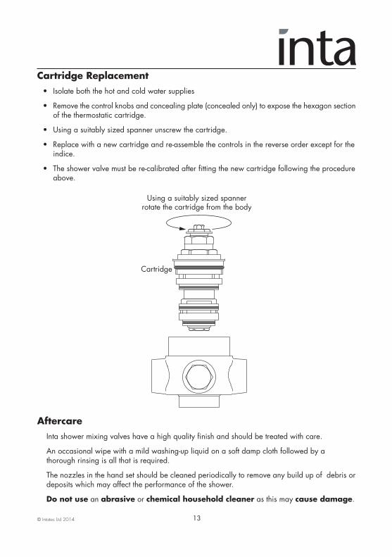
Cartridge Replacement • Isolate both the hot and cold water supplies
• Remove the control knobs and concealing plate (concealed only) to expose the hexagon sectionof the thermostatic cartridge.
• Using a suitably sized spanner unscrew the cartridge.
• Replace with a new cartridge and re-assemble the controls in the reverse order except for the indice.
• The shower valve must be re-calibrated after fitting the new cartridge following the procedure above.
Cartridge
Using a suitably sized spannerrotate the cartridge from the body
© Intatec Ltd 2014 14
SparesA full range of spares are available for this product.
PLEASE NOTE: Only genuine spares should be used.
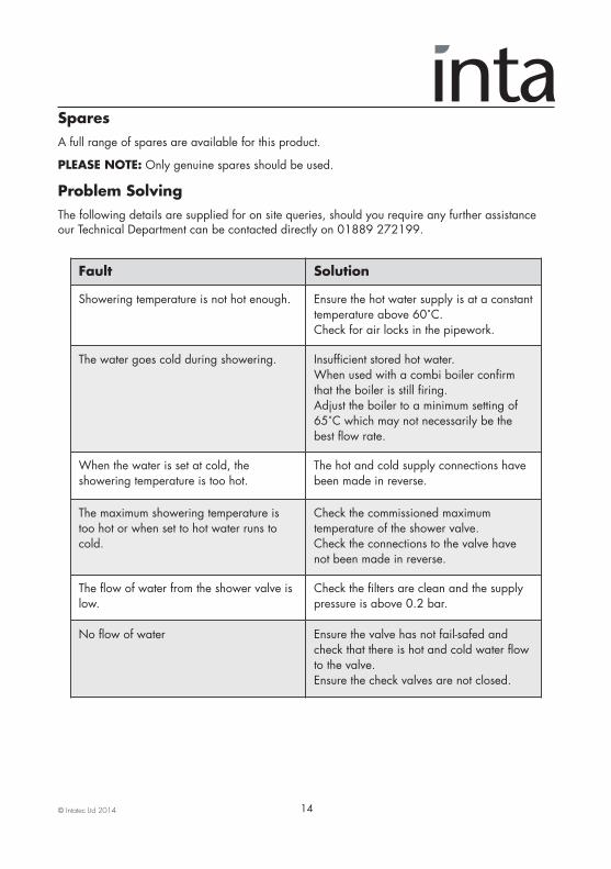
Problem SolvingThe following details are supplied for on site queries, should you require any further assistanceour Technical Department can be contacted directly on 01889 272199.
Fault Solution
Showering temperature is not hot enough. Ensure the hot water supply is at a constanttemperature above 60˚C.Check for air locks in the pipework.
The water goes cold during showering. Insufficient stored hot water. When used with a combi boiler confirmthat the boiler is still firing.Adjust the boiler to a minimum setting of65˚C which may not necessarily be thebest flow rate.
When the water is set at cold, theshowering temperature is too hot.
The hot and cold supply connections havebeen made in reverse.
The maximum showering temperature istoo hot or when set to hot water runs tocold.
Check the commissioned maximumtemperature of the shower valve.Check the connections to the valve havenot been made in reverse.
The flow of water from the shower valve islow.
Check the filters are clean and the supplypressure is above 0.2 bar.
No flow of water Ensure the valve has not fail-safed andcheck that there is hot and cold water flowto the valve.Ensure the check valves are not closed.

© Intatec Ltd 2014
Intatec LtdAirfield Industrial Estate
HixonStaffordshireST18 0PF
Tel: 01889 272 180Fax: 01889 272 181
email: [email protected]: www.intatec.co.ukE & O.E
02-12-14
Notes
To active your product warranty please visitwww.intatec.co.uk
and click on Product Registration
Please leave this Manual for the User