THERMOSTATIC SHOWER VALVE 20007013000 - … · 20007013000 TROUBLE SHOOTING SYMPTOM SOLUTION After...
4
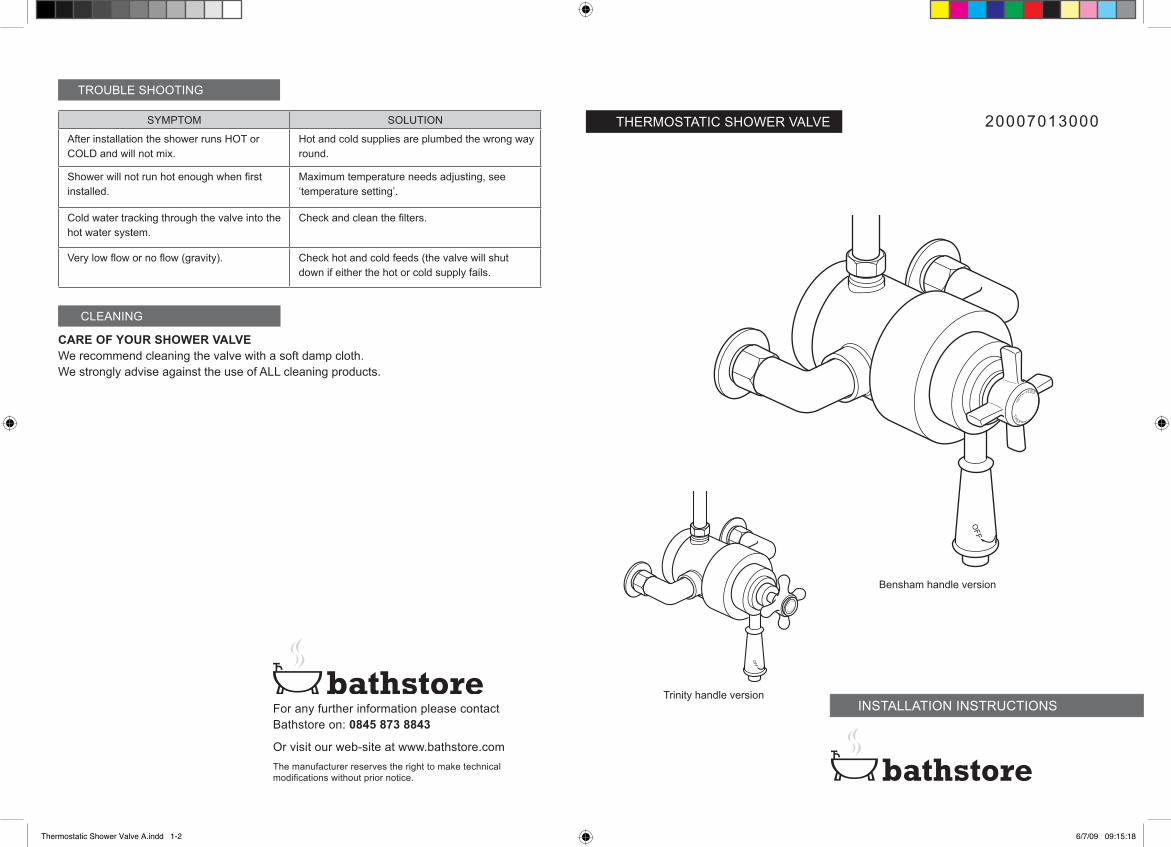
20007013000 TROUBLE SHOOTING SYMPTOM SOLUTION After installation the shower runs HOT or COLD and will not mix. Hot and cold supplies are plumbed the wrong way round. Shower will not run hot enough when first installed. Maximum temperature needs adjusting, see ‘temperature setting’. Cold water tracking through the valve into the hot water system. Check and clean the filters. Very low flow or no flow (gravity). Check hot and cold feeds (the valve will shut down if either the hot or cold supply fails. CLEANING CARE OF YOUR SHOWER VALVE We recommend cleaning the valve with a soft damp cloth. We strongly advise against the use of ALL cleaning products. Trinity handle version Bensham handle version For any further information please contact Bathstore on: 0845 873 8843 Or visit our web-site at www.bathstore.com The manufacturer reserves the right to make technical modifications without prior notice. THERMOSTATIC SHOWER VALVE INSTALLATION INSTRUCTIONS Thermostatic Shower Valve A.indd 1-2 6/7/09 09:15:18
Transcript of THERMOSTATIC SHOWER VALVE 20007013000 - … · 20007013000 TROUBLE SHOOTING SYMPTOM SOLUTION After...
20007013000
TROUBLE SHOOTING
SYMPTOM SOLUTION
After installation the shower runs HOT or COLD and will not mix.
Hot and cold supplies are plumbed the wrong way round.
Shower will not run hot enough when first installed.
Maximum temperature needs adjusting, see ‘temperature setting’.
Cold water tracking through the valve into the hot water system.
Check and clean the filters.
Very low flow or no flow (gravity). Check hot and cold feeds (the valve will shut down if either the hot or cold supply fails.
CLEANING
CARE OF YOUR SHOWER VALVEWe recommend cleaning the valve with a soft damp cloth. We strongly advise against the use of ALL cleaning products.
Trinity handle version
Bensham handle version
For any further information please contact Bathstore on: 0845 873 8843
Or visit our web-site at www.bathstore.comThe manufacturer reserves the right to make technical modifications without prior notice.
THERMOSTATIC SHOWER VALVE
INSTALLATION INSTRUCTIONS
Thermostatic Shower Valve A.indd 1-2 6/7/09 09:15:18

20007013000
21
INTRODUCTION DIMENSIONS
150
NOTE: ALL DIMENSIONS IN MILLIMETRES
30
110
113
Please read these instructions carefully and keep in a safe place for future reference.General Installation RequirementsThe installation must comply with regulations of the Local Water Authority as contained in their bylaws. All of the taps in this range are single flow (the hot and cold water mix in the body) and should therefore be supplied with hot and cold water at balanced pressures, both from the tank or both from the mains (via a combination boiler for example). If the taps are not supplied at balanced pressures then the mixer will not function correctly. It will also be necessary to fit non-return valves on both hot and cold feeds. It is very important that all pipe work is flushed thoroughly after installation to avoid damaging the ceramic discs.Minimum/Maximum working pressureThese taps are suitable for high and low pressure installations they are fitted with a ceramic disc cartridge which provides a good flow rate with very smooth movement. To ensure that the mixer works adequately under low pressure, the cold water storage tank should be at least 2 metres above the highest installed position. The maximum water pressure is 10 bar (note: mains cold water is normally supplied at between 2 and 3 bar). For installations where the mains pressure exceeds 5 bar a pressure reducing valve should be fitted.ApprovalsAll products are manufactured using materials tested and approved under the Water Bylaws Scheme and comply with requirements of British Standard 5412: 1996 where applicable.Preparation and bylaw requirementsThese taps are single flow so the hot and cold water mix in the body. Water bylaws require that where the hot water is supplied from a tank and cold from the mains, non return valves are fitted on both hot and cold pipes as close as possible to the tap. These are not supplied. Where combination boilers are fitted it is only necessary to shut off the incoming mains and turn the boiler off, non return valves are not required.WARNINGBefore installing the new mixer it is essential that you thoroughly flush through the supply pipes in order to remove any remaining swarf, solder or other impurities.Failure to carry out this simple procedure could cause problems or damage to the workings of the mixer.These hints have been prepared for your guidance, you must exercise due care at all times.We do not accept responsibility for any problems that may occur through incorrect installation.
74
160.5
82
62
G1/2”
Thermostatic Shower Valve A.indd 3-4 6/7/09 09:15:19

20007013000
43
OPERATION
FIG. 1 PREPARING INLET CONNECTIONS & BACK PLATE
INSTALLATION INSTALLATION
First shut off your water heating system then, with your mains stop cock closed, open the lowest hot and cold taps in the house and allow to run until the cold storage tank and pipes are empty (the hot water storage cylinder always remains full).Where combination boilers are fitted it is only necessary to turn off the boiler and shut off the incoming mains.Fitting isolating valves to the inlet feeds is recommended for ease of maintenance.
INSTALLATIONRemember to turn off the mains water supply before connecting to any existing pipe work.Warning! Please check for any hidden pipes and cables before drilling holes in the wall.
Preparation.Prepare the supply pipes (hot on the left and cold on the right) at the required height with a width of 150mm centres, making the ends of the pipes 25mm out from the face of the wall, see fig 1.Remove the nuts and olives and place the valve over pipes, mark the position of the back plate and remove. Remove the back plate from the valve by loosening the grub screw underneath, position the back plate onto the wall with the grub screw at the bottom and mark the position of the 3 holes. Drill the 3 x 6mm holes to a depth of 40mm and insert the wall plugs. Fix the back plate to the wall with the supplied screwsValve.Slide the cover plates onto the nuts and position on each pipe with the cover plate against the wall, slide an olive onto each pipe. Push the valve over each pipe and into the back plate, tighten the 2 nuts onto hot and cold inlet, and then the grub screw underneath the valve.Finally connect the valve the riser. Note: There is the option to fit the valve as described and then move the stopper from bottom outlet to the top. This will allow for a flexible hose to be used.Having first checked all new connections, turn on the mains stop cock, close all taps except the new valves and as the system starts to refill check for leaks.Once you have satisfied yourself that there are no leaks, switch on the water heating.
150mm
FLOW CONTROL HANDLE
BACK PLATE
HOT INLET
COLD INLET
COLD INLET
TEMPERATURECONTROL HANDLE
HOT INLET
NUT
COVER PLATE
OLIVE
HOT INLET PIPE
OLIVE
NUT
COVER PLATE
COLD INLET PIPE
BACK PLATE
BACK PLATE SCREWS
Turn the Flow control handle to turn on and off and to increase/decrease the flow of water. Turn the Temperature control handle to increase/decrease the temperature.
To change the set temperature see section on page 5 Temperature setting.
FLOW CONTROL HANDLE
GRUB SCREW
TEMPERATURE CONTROL HANDLE
BOTTOM OUTLET
RISER OUTLET
Thermostatic Shower Valve A.indd 5-6 6/7/09 09:15:20

20007013000
65
TEMPERATURE SETTING REFITTING HANDLES
Wash the cartridge with clean running water, dry and lightly grease the seal. Fit cartridge in body ensuring location lug engages with lower slot on body, Push the cartridge firmly into the body as far as it will go.
Screw on the cartridge retaining ring, hand tight only. A light tap with a punch on one of the ring projections will ensure the ring remains tight.
Turn on water supply. Place flow control handle over large spline and slowly turn clockwise until water flow stops. Tighten handle a further 1/8 of a turn, then remove handle.
Fit the flow control stop ring over the four lugs on the front of the cartridge, with the stop end face in the desired position (at the bottom vertical).
Screw the front cover shroud onto the cartridge retaining ring, as far as it will go, ensuring the flow control stop ring is firmly held in position.
Without rotating, position the flow control handle and washer over the large spline so that the edge of the screw is adjacent to the stop end face. Tighten the screw on to the splines and fit decorative lever. Refit the temperature control handle and cover.
The control handles on this product are factory set and should require no adjustment. However, if for any reason the handles and/or the mixing cartridge is removed it is important the following procedure is employed to ensure trouble-free use.
Turn flow control anti-clockwise to maximum flow position, and temperature control anti-clockwise until it contacts the internal limit stop.Allow water temperature to stabilise (about 3 minutes) and check temperature. Proceed if temperature is NOT 43°C.
Shut off the water flow. Unscrew the decorative cover on the temperature control handle. Unscrew and remove the handle retaining screw and keep in a safe place. Pull off the handle and note the position of the internal limit stop.
Temporarily refit the temperature control handle until it just engages on the splines of the spindle. Turn on the water.Slowly turn the handle in the required direction until the discharge temperature is achieved. Remove the handle when finished.
Without rotating the temperature spindle, replace the handle so that Face A is directly adjacent to Face B. Refit and tighten the screw. Refit the decorative handle cover.
TEMPERATURE CONTROL HANDLE
LIMIT STOP
TEMPERATURE CONTROL HANDLE
LIMIT STOP FACE A
FACE B
STOP END FACE
HANDLE STOP END FACE
SLOT IN BODY
FLOW CONTROL
TEMPERATURE CONTROL
WASHER
STOP END FACE
STOP RING
Without rotating the temperature spindle, place the handle so that Face A is directly adjacent to Face B on the spindle. Tighten the grub screw. Screw on the cover.
LIMIT STOP FACE AFACE B
OPTIONAL HANDLE
COVER
GRUB SCREW
1
2
3
4
1
2
3
4
5
6
Thermostatic Shower Valve A.indd 7-8 6/7/09 09:15:25