HP Care thermostatic mixer shower - SYNC Living · 2019-02-20 · HP Care thermostatic mixer shower...
24
Transcript of HP Care thermostatic mixer shower - SYNC Living · 2019-02-20 · HP Care thermostatic mixer shower...

HP Care thermostatic mixer shower
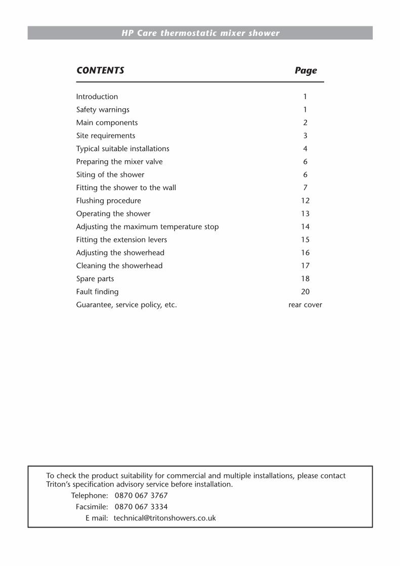
Introduction 1
Safety warnings 1
Main components 2
Site requirements 3
Typical suitable installations 4
Preparing the mixer valve 6
Siting of the shower 6
Fitting the shower to the wall 7
Flushing procedure 12
Operating the shower 13
Adjusting the maximum temperature stop 14
Fitting the extension levers 15
Adjusting the showerhead 16
Cleaning the showerhead 17
Spare parts 18
Fault finding 20
Guarantee, service policy, etc. rear cover
CONTENTS Page
To check the product suitability for commercial and multiple installations, please contact Triton’s specification advisory service before installation.
Telephone: 0870 067 3767Facsimile: 0870 067 3334
E mail: [email protected]

HP Care thermostatic mixer shower
1
This book contains all the necessary fitting and operating instructions for your Triton high pressure care thermostatic mixer shower. Please read them carefully. Read through the whole of this book before beginning your installation.
The shower installation MUST be carried out by a suitably competent person and in sequence of this instruction book.
Care taken during the installation will provide a long and trouble free life from your shower.
Thermostatic mixers will automatically maintain your chosen temperature, even if taps are turned on elsewhere in the house, and shut off if either the hot or cold supply fails.
For the best performance within the specified running pressure range a minimum flow of 8 litres per minute should be available to both inlets.
This mixer is designed to operate on higher pressure systems found in the UK up to a maximum of 5 bar running pressure. The valve MUST NOT be subjected to water temperatures above 80°C.
The high pressure valve is suitable for modulating type combination boilers and multi-point hot water heaters. It is also suitable for thermal storage, unvented systems and pumped gravity systems.
IMPORTANT: Before fitting with a gas instantaneous water heater, make sure the appliance is capable of delivering hot water at a minimum switch-on flow rate of 3 litres per minute. At flow rates between 3 and 8 litres per minute the appliance must be able to raise the water temperature to a minimum of 52°C.
The water temperature at the inlet to the mixer must remain relatively constant when flow rate adjustments are made.
a. Layout and sizing of pipework must be such that when other services are used, pressures at the shower control inlets DO NOT fall below the recommended minimum.
b. DO NOT choose a position where the shower could become frozen.
c. The outlet of this appliance MUST NOT be connected to any form of tap or fitting not recommended by the manufacturer.
d. The showerhead MUST be cleaned regularly to remove scale and debris.
e. Conveniently situated isolating valves in each inlet supply MUST be fitted as an independent method of isolating the shower should maintenance or servicing be necessary.
f. If it is intended to operate the shower in areas of hard water (above 200 ppm temporary hardness), a scale inhibitor may have to be fitted.
g. DO NOT operate the shower outside the guidelines as laid out in ‘site requirements’.
h. Persons who may have difficulty understanding or operating the shower controls should not be left unattended while showering. Special consideration should be given to young children and the less able bodied.
INTRODUCTIONINTRODUCTION SAFETY WARNINGSSAFETY WARNINGS
Y-002-A
Y-003-AReplacement parts can be ordered from Customer Service. See ‘spare parts’ for details and part numbers.

HP Care thermostatic mixer shower
2
Fig.1
1. Inlet nuts and olives
2. Inlet elbows
3. Valve housing
4. Outlet adaptor
5. Outlet nut and olive
6. Outlet blanking plug
7. Cartridge assembly
8. Flow knob
9. Temperature knob
10. Knob trim
11. Max. temperature override button
12. Cover
13. Inlet trims
14. Outlet trim
15. Outlet blanking trim
16. Nut covers
17. Pipe trims
18. Trim ring
19. Cartridge fixing screws
20. Hexagonal nut
21. Flow control extension lever
22. Temperature control extension lever
MAIN COMPONENTSMAIN COMPONENTS (fig.1)
1
1
5
4
32
2
6
7
19
8
19
11
910
21
22
17
20
13
16
16 16
13
12
15
18

HP Care thermostatic mixer shower
3
The installation must be in accordance with Water Regulations and Bylaws.
Minimum running water pressure: 1 bar.
Maximum running water pressure: 5 bar.
Maximum static water pressure: 10 bar.
For the best performance within the specified running pressure range a minimum flow of 8 litres per minute should be available to both inlets.
While the mixer valve is operational (open outlet), inlet pressures must not be capable of exceeding 7 bar. For effective operation of the internal seals, the maximum static pressure must not be exceeded.
Note: On sites where the running pressure is above 5 bar, the use of a suitably sized pressure reducing valve fitted in the cold mains supply pipework can provide nominally equal pressures at the mixer valve. This should be installed as indicated on the appropriate diagrams shown on the following pages, and set to within the specification of the valve.
For the best performance of this shower both hot and cold water supplies to the shower valve should be fed at nominally equal pressures.The pipework should be installed such that the flow is not significantly affected by other taps and appliances being operated elsewhere on the premises.
Note: Where thermal store/combi boilers or multi-point heaters are used, if excessive draw-offs take place the boiler may not be able to maintain an adequate output temperature. This could result in the shower temperature becoming noticeably cooler.
For effective thermostatic control the temperature of the hot water entering the mixer should remain a minimum of 10°C above the selected output temperature.
The supply pipework must be flushed to clear debris before connecting to the shower control accordance with Water Regulations and Bylaws.
DO NOT use jointing compounds on pipework.
SITE REQUIREMENTSSITE REQUIREMENTS

HP Care thermostatic mixer shower
4
a) Instantaneous gas-heated showers, e.g. combination boilers (fig.2)
The shower control must be installed with a multipoint gas water heater or combination boiler of a fully modulating design (i.e. where the water draw-off rate indirectly controls the gas flow to the burner). A drop tight pressure reducing valve must be fitted if the supply pressures exceed 5 bar maintained.
An expansion vessel (shown in fig.2) must be fitted, and regularly maintained, to make sure the unit is not damaged by excess pressures. This may already be installed within the boiler (check with manufacturer) and is in addition to the normally larger central heating expansion vessel.
The layout and sizing of pipework must be such that nominally equal inlet supply pressures are achieved and the effects of other draw-offs are minimised. The hot supply temperature must remain a minimum of 10°C hotter than the required blend temperature for the best performance.
b) Unvented mains pressure showers (fig.3)
The shower control can be installed with an unvented, stored hot water cylinder.
For systems with no cold water take off after the appliance reducing valve, it will be necessary to fit an additional drop tight pressure reducing valve when the mains pressure is over 5 bar. The drop tight pressure reducing valve must be set at the same value as the unvented package pressure reducing valve.
Note: An additional expansion vessel (shown in fig.4) may be required if a second pressure reducing valve is installed. This does not apply to packages with a cold take off after the pressure reducing valve to the cylinder.
The layout and sizing of pipework must be such that nominally equal inlet supply pressures are achieved and the effects of other draw-offs are minimised.
Combinationboiler
Showermixer valve
Servicevalves
Hot water
Expansionvessel
Coldmainssupply
Stop tap
Pressurereducing valve
CH flow
CH return
Fig.2 diagrammatic view (not to scale)
Blendervalve
Flow
Cold mains supply
Hotwater
Stop tap
Expansionvessel
Pressurereducing valve Return
Servicevalves
Mixer valve
Boiler
Fig.5 diagrammatic view (not to scale)
TYPICAL SUITABLE INSTALLATIONSTYPICAL SUITABLE INSTALLATIONS

HP Care thermostatic mixer shower
5
Servicevalves
Balanced cold mains supply
Cold mains supply
Mixershower
Expansionvessel
Pressurereducing
valve
Pressurereducing valve
Stop tap
Unventedhot water
storage unit
Safety devicesnot shown
Fig.4 diagrammatic view (not to scale)
c) Mains pressurised thermal store (fig.4)
Packages of this type, fitted with a tempering valve (blender valve) can be used. A drop tight pressure reducing valve must be fitted if the supply pressures exceed 5 bar maintained.
An expansion vessel (shown in fig.5) must be fitted, and regularly maintained, to make sure the unit is not damaged by excess pressures. This may already be installed externally or internally within the thermal store (check with thermal store manufacturer).
The layout and sizing of pipework must be such that nominally equal inlet supply pressures are achieved and the effects of other draw-offs are minimised.
d) Pump assisted gravity fed systems (fig.5)
The pump must be fed from a cold water cistern and hot water cylinder providing nominally equal water pressures. The pump must be capable of maintaining running pressures of 1 bar.
Hot watercylinder
Mixer
Cold supply
Hotsupply
Alternative supply(must be belowvent pipe tee)
Coldwatermainssupply
Drainvalve
Gatevalve
Stop valve
Cold watercistern
Minimum head
Otherdraw-offs
Draw-off must pointdown to avoid airlock
issues
Ring mainIsolating switch
or pull cordswitch (bothfused at 3A)
Servicevalve
Servicevalve
Pump
Fig.3 diagrammatic view (not to scale)

HP Care thermostatic mixer shower
6
Before starting the installation, make sure all the openings on the valve are carefully covered to prevent ingress of any debris etc.
Note: It is not necessary to remove the control knobs at any stage.
SITING OF THE SHOWERSITING OF THE SHOWER
W-008-AWARNING!
The shower must not be positioned where it will be subjected to freezing
conditions.
Refer to fig.6 for correct siting of the shower.
Position the shower and showerhead on the wall so that all controls can be comfortably reached while using the shower. The showerhead and riser rail can be positioned either side of the shower.
Note: Pipe entry for both surface-mounted and flush-fitted valves can be from the top, bottom or rear.
The hot entry port is on the left-hand side of the valve and is marked on the valve with a letter ‘H’ (fig.7).
Valve unit can be mounted either side of the riser rail
Height of unit should be a minimum of
1 metre from floor
Height ofshowerheadto suit user’srequirement
Fig.6 diagrammatic view (not to scale)
Fig.7
PREPARING THE MIXER VALVEPREPARING THE MIXER VALVE

HP Care thermostatic mixer shower
7
Note: The outlet of the shower must not be connected to anything other than the hose and showerhead supplied.
DO NOT use jointing compounds on any pipe fittings for the installation.
DO NOT solder fittings near the shower unit, as heat can transfer along the pipework and damage components.
Note: Suitable isolating valves (complying with Water Regulations) must be fitted on the hot and cold water supplies to the shower as an independent means of isolating water supplies should maintenance or servicing be necessary.
When connecting pipework avoid using tight 90° elbows. Swept or formed bends will give the best performance.
IMPORTANT: The water circuit should be installed such that the flow is not significantly affected by other taps and appliances being operated elsewhere on the premises. Water pressure must not fall below specification of the shower.
Note: The hot water pipe entry must be on the left.
Rising and falling suppliesHaving decided on the position of the shower and direction of pipe entry, complete the pipework to the shower area.
Note: The final separation between pipe centres needs to be about 153 mm but absolute accuracy is not needed as the inlet elbows are adjustable between 146 mm and 160 mm.
Flush pipework to clear the system of all debris and check for leaks.
IMPORTANT: The inlet elbows contain check valves that may be damaged if debris is not flushed through prior to fitting.
Where this is not possible refer to the ‘flushing procedure’ on page 12.
Clip the pipework to the wall surface so that the pipe centres are 21 mm off the wall.
Offer the valve, together with the inlet elbows, to the pipework. Make sure the inlet elbow grub screws (fig.8) are slack allowing the inlet
Fig.8
=
=
=
=
Fig.10
Fig.9
Long
side
Fig.12Fig.11
FITTING THE SHOWER TO THE WALLFITTING THE SHOWER TO THE WALL

HP Care thermostatic mixer shower
8
elbows to rotate to the correct position and move freely in and out of the valve housing.
Place the valve housing centrally between the two pipes, and mark the two diagonal fixing holes – (fig.9) and (fig.10).
Remove the valve. Drill and plug the holes. (The wall plugs supplied are suitable for most brick walls – use an appropriate masonry drill, but if wall is plasterboard or a soft building block, you must use suitable wall plugs and an appropriate drill bit).
Fit the nut covers on to the pipes (fig.11).
Note: Slide the pipes into the small diameter end of the nut cover. It will not fit if inserted from the other end. Slide the inlet nuts and olives onto the pipes, followed by the inlet trims.
Note: The holes in the inlet trims are offset to allow for adjustable inlet pipe separation widths. If pipe centre separation is 153 mm or less, then have the short side of the inlet trims between the pipes. If the pipe separation gap is 153 mm or greater, have the long side of the inlet trims between the pipes (fig.12). If in any doubt try the cover to see if it fits properly (i.e. no visible gaps between the inlet trims and the cover (fig.13). If there is a gap (fig.14) then reverse the trim.
While trying the cover make sure the inlet nuts are sitting in the holes in the inlet trim holes so that the inlet trims are at the correct separation.
Having positioned the inlet trims correctly, refit the valve to the pipework. Make sure the hot inlet port (marked with the letter ‘H’ on the valve housing) is connected to the hot pipework which must be on the left.
Screw to the wall with the two screws supplied (fig.15). Tighten the inlet nuts and inlet elbow grub screws.
Fit the outlet adaptor into the bottom outlet hole in the valve housing (fig.16). The adaptor is sealed with an ‘O’ ring.
Make sure the adaptor is fitted with the pipe end (fig.17) in the valve housing.
Fit the blanking plug into the top outlet hole using an ‘O’ ring to seal it (fig.18).
Fig.13 Fig.14
Fig.15
Fig.16
Hose end(flat)
Pipe end(chamfered)
Fig.17
HP Care thermostatic mixer shower
9
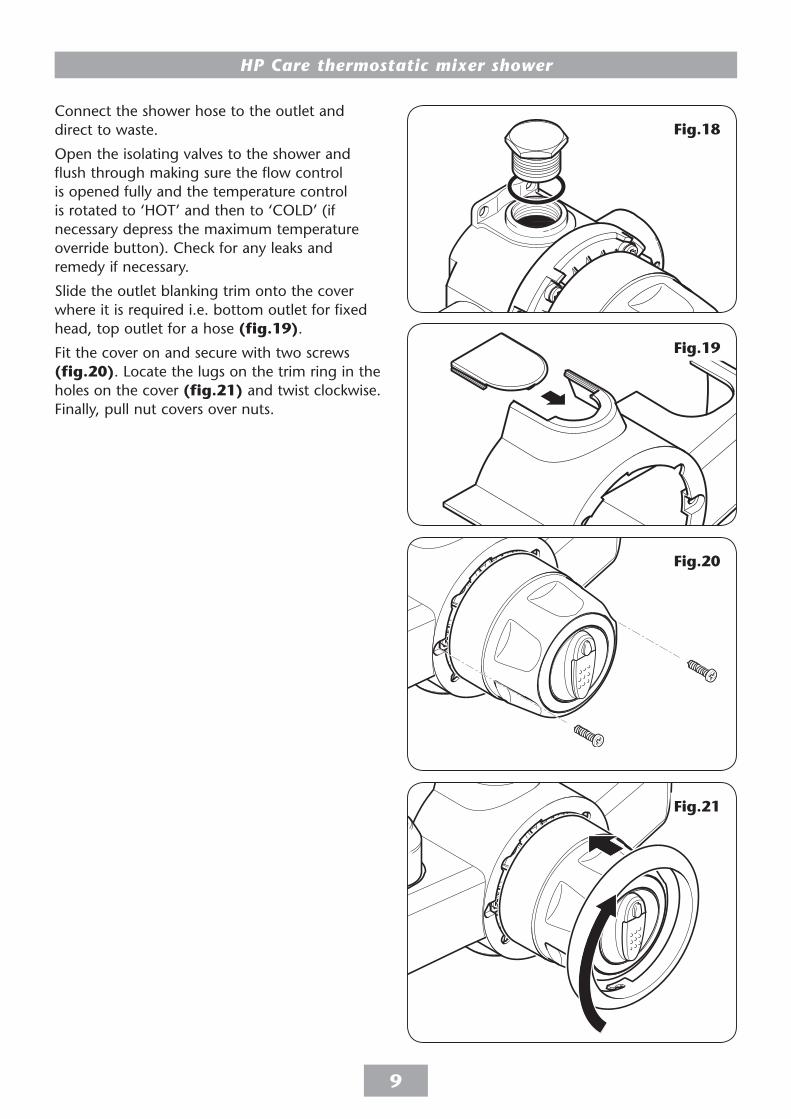
Connect the shower hose to the outlet and direct to waste.
Open the isolating valves to the shower and flush through making sure the flow control is opened fully and the temperature control is rotated to ‘HOT’ and then to ‘COLD’ (if necessary depress the maximum temperature override button). Check for any leaks and remedy if necessary.
Slide the outlet blanking trim onto the cover where it is required i.e. bottom outlet for fixed head, top outlet for a hose (fig.19).
Fit the cover on and secure with two screws (fig.20). Locate the lugs on the trim ring in the holes on the cover (fig.21) and twist clockwise. Finally, pull nut covers over nuts.
Fig.20
Fig.18
Fig.19
Fig.21

HP Care thermostatic mixer shower
10
Rear entry suppliesNote: The final separation between pipe centres needs to be about 153 mm (fig.22) but absolute accuracy is not essential as the inlet elbows are adjustable between 146 mm and 160 mm.
Using a spirit level, mark the route of incoming hot and cold water supply pipes at a distance of 153 mm centres.
Remove the plaster and brickwork to the required depth to conceal the supply pipework.
Note: It is advisable that pipework installed in solid walls be provided with enough free play inside a cavity to enable entry into the inlet elbows for tightening, before securing the valve to the finished wall surface.
Install the hot and cold pipework – the hot pipe must enter from the left. Make sure the finished pipework projects from the front face of the tiled surface of the wall by 9.5 mm (fig.23).
Allow for two circular recesses measuring 32 mm diameter by 14 mm depth, to accept the rear entry pipe trims (fig.22).
Flush pipework to clear the system of all debris and check for leaks.
IMPORTANT: The inlet elbows contain check valves that may be damaged if debris is not flushed through prior to fitting.
Where this is not possible refer to the ’flushing procedure’ on page 12.
Make good the wall and complete the tiling. Check that the rear entry pipe trims (fig.23) are sealed in with either silicon sealant or grout.
Note: Failure to fit the rear entry pipe trims could result in ingress of water into the wall cavity.
Offer the valve, together with the inlet elbows, to the pipework making sure the inlet elbow grub screws are slack allowing the inlet elbows to be rotated to the correct position and move freely in and out of the valve housing (fig.8).
=
=Fig.24
32 mm
dia.
9.5 mm
153 mm approx
Fig.22
9.5mm
Pipetrim
Inletnut
Fig.23

HP Care thermostatic mixer shower
11
Make sure the valve is central between the two pipes and mark the two diagonal fixing holes (figs.24 and 25).
Remove the valve. Drill and plug the holes using the wall plugs provided. (The wall plugs supplied are suitable for most brick walls – use an appropriate masonry drill, but if wall is plasterboard or a soft building block, you must use suitable wall plugs and an appropriate drill bit).
Using two hexagonal nuts (supplied), refit the valve to the pipework. Make sure the hot inlet port (marked with the letter ‘H’ on the valve housing) is connected to the hot pipework which must be on the left.
Tighten the inlet nuts with the spanner supplied (fig.26) then tighten the inlet elbow grub screws.
Fit the outlet adaptor into the bottom outlet hole in the valve housing (fig.16). The adaptor is sealed with an ‘O’ ring. Make sure the adaptor is fitted with the pipe end (fig.17) in the valve housing.
Fit the blanking plug into the top outlet hole using an ‘O’ ring to seal it (fig.18).
Connect the shower hose to the outlet and direct to waste.
Open the isolating valves to the shower and flush through, making sure the flow control is opened fully and the temperature control is rotated to ‘HOT’ and then to ‘COLD’ (if necessary depress the maximum temperature override button). Check for any leaks and remedy if necessary.
Slide the top outlet blanking trim onto the top cover outlet (fig.19).
Fit the inlet blanking trims on the underside of the cover (fig.27) and slide the cover on. Secure the cover with two screws (fig.20). Locate the lugs on the trim ring in the holes on the cover (fig.21) and twist clockwise.
Fig.26
=
=
Fig.25
Fig.27
HP Care thermostatic mixer shower
12
Fig.31
Fig.28
Fig.30
Fig.29
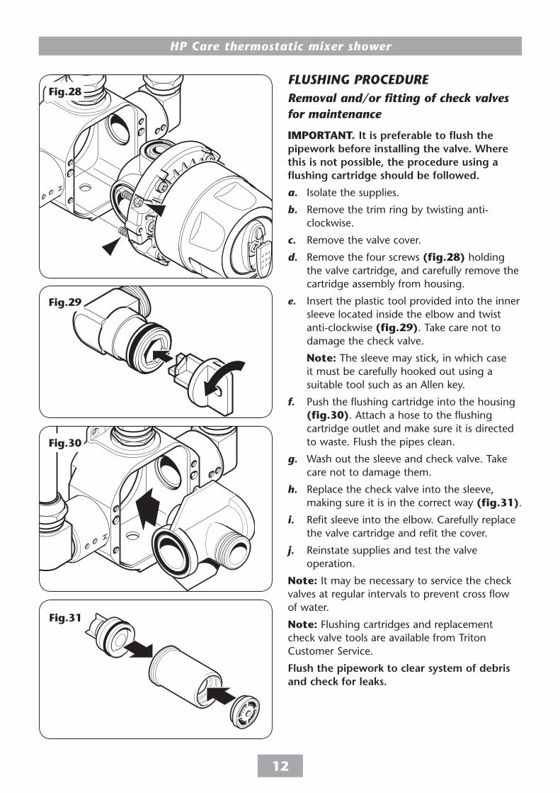
Removal and/or fitting of check valves for maintenance
IMPORTANT. It is preferable to flush the pipework before installing the valve. Where this is not possible, the procedure using a flushing cartridge should be followed.
a. Isolate the supplies.
b. Remove the trim ring by twisting anti-clockwise.
c. Remove the valve cover.
d. Remove the four screws (fig.28) holding the valve cartridge, and carefully remove the cartridge assembly from housing.
e. Insert the plastic tool provided into the inner sleeve located inside the elbow and twist anti-clockwise (fig.29). Take care not to damage the check valve.
Note: The sleeve may stick, in which case it must be carefully hooked out using a suitable tool such as an Allen key.
f. Push the flushing cartridge into the housing (fig.30). Attach a hose to the flushing cartridge outlet and make sure it is directed to waste. Flush the pipes clean.
g. Wash out the sleeve and check valve. Take care not to damage them.
h. Replace the check valve into the sleeve, making sure it is in the correct way (fig.31).
i. Refit sleeve into the elbow. Carefully replace the valve cartridge and refit the cover.
j. Reinstate supplies and test the valve operation.
Note: It may be necessary to service the check valves at regular intervals to prevent cross flow of water.
Note: Flushing cartridges and replacement check valve tools are available from Triton Customer Service.
Flush the pipework to clear system of debris and check for leaks.
FLUSHING PROCEDUREFLUSHING PROCEDURE

HP Care thermostatic mixer shower
13
Make sure all plumbing supplies are connected and turned on.
Starting the showerTo start the shower, rotate the outer knob (flow control) anti-clockwise (fig.32).
Adjusting the shower temperatureTo adjust the temperature, rotate the inner knob – temperature control (fig.33). The temperature disc is numbered for ease of use. The temperature disc ranges from 1 (fully cold) to 10 (fully hot).
Once at the preferred temperature, no further adjustment is required, providing the hot and cold water supplies remain constant.
Stopping the showerTo stop the shower turn the flow control clockwise to the stop position (fig.34). This automatically stops the water flow.
As a safety measure the shower has a built-in maximum temperature stop to prevent accidentally exceeding the highest desired temperature. The stop comes in a factory set position. (If adjustment is required see ‘Adjusting the maximum temperature stop’ on page 14).
To override this stop, depress the button (fig.35) and turn the control clockwise to the higher settings. To return to the normal temperature range just turn the temperature control anti-clockwise until it is past the maximum temperature stop.
Note: Make sure that the temperature control is in the normal temperature range when the shower is turned off.
Flow control
Temperaturecontrol
Flow control
Fig.32
Fig.33
Fig.34
Maximumtemperature
overridebutton
Fig.35
OPERATING THE SHOWEROPERATING THE SHOWER

HP Care thermostatic mixer shower
14
Not available if extension levers are fitted.
As a safety measure the shower has a built-in maximum temperature stop to prevent you accidentally exceeding your highest desired temperature. This is set in the factory to provide a maximum temperature of 42°C based on the hot and cold water supplies being 65°C and 15°C respectively at nominally equal pressures.
ProcedureTo adjust the maximum temperature stop, first rotate the temperature knob to the 12 o’clock position.
Remove the temperature knob trim using a thin bladed screwdriver (fig.36).
Unscrew the central fixing screw (fig.37) and remove the temperature control knob. Now remove the temperature control disc, together with the wavy washer. The control disc houses the maximum temperature stop mechanism (fig.38).
To increase the temperature stop setting, reposition the temperature stop mechanism clockwise within the arc of the grooves (fig.38).
To decrease the temperature stop setting, reposition the stop mechanism anti-clockwise within the arc of the grooves.
When the stop mechanism is set at the preferred position, refit the temperature control disc making sure the name ‘Triton’ is at the bottom.
Replace the wavy washer, then refit the temperature control knob, making sure it is replaced in the same attitude as when removed (i.e. 12 o’clock position).
Refit the central screw and replace the knob trim.
IMPORTANT. Only adjust the maximum temperature stop when the hot water is at its usual supply temperature.
Fixing screw
Temperaturecontrol knob
Temperaturecontrol disc
Fig.36
Fig.37
Maximum temperature stop mechanism
(Decrease stop position) (Increase stop position)
Grooves
Temperature control disc
T
R
I
T
O
N
T
R
I
T
O
N
Fig.38
ADJUSTING THE MAXIMUM TEMPERATURE STOP
ADJUSTING THE MAXIMUM TEMPERATURE STOP

HP Care thermostatic mixer shower
15
IMPORTANT: Fitting the temperature control extension lever will mean the maximum temperature override button facility will be lost.
ProcedureOn the valve rotate the temperature control to the 12 o’clock position (fig.39).
Remove the knob trim with a thin bladed screwdriver (fig.40).
Note: Remove the serial number label from inside the knob trim and replace it inside the new knob trim.
Unscrew the central fixing screw (fig.41) and remove the temperature control knob (fig.42). These three items – trim, screw and control knob – can now be discarded.
Note: Make sure to keep in place the wavy washer and plastic maximum temperature mechanism.
Place the flow control extension lever over the valve flow control (fig.43). The position can be altered to suit any of the six indented recesses on the flow control knob. Screw the two locking screws, (figs.44 and 45), which will hold the extension lever tight on the existing flow control.
Fit the temperature control extension lever (fig.46) making sure it is placed in the same attitude as the discarded temperature control (12 o’clock position). Lock into position by using the new central fixing screw (fig.47).
Fit the new knob trim (fig.48) into the temperature control extension lever by inserting the narrow end in first.
Fig.39 Fig.40
Fig.41 Fig.42
Fig.43 Fig.44
Fig.45 Fig.46
Fig.47 Fig.48
FITTING THE EXTENSION LEVERSFITTING THE EXTENSION LEVERS

HP Care thermostatic mixer shower
16
Fig.A1Fig.49 Five showerhead patterns are available (fig.49). Adjust the spray pattern by turning the bezel on the showerhead in either direction until the desired pattern is obtained.
ADJUSTING THE SHOWERHEADADJUSTING THE SHOWERHEAD

HP Care thermostatic mixer shower
17
Sprayplatekey
Sprayplate
Fig.50
Fig.51
Before cleaning, turn off the unit at the isolation switch to avoid the shower being accidentally switched on.
IT IS IMPORTANT TO KEEP THE SHOWERHEAD CLEAN TO MAINTAIN THE PERFORMANCE OF THE SHOWER. The hardness of the water will determine the frequency of cleaning. For example, if the shower is used every day in a very hard water area, it may be necessary to clean the showerhead on a weekly basis.
Sprayplate removalThere is no need to remove the showerhead from the hose.
Using the removal tool supplied (fig.50), locate the raised ’bosses’ into the recesses in the sprayplate. Hold in firmly and twist anti-clockwise (fig.51). This movement may turn the cartridge assembly as well until it reaches a ‘stop’.
Hold the cartridge firmly and continue to twist anti-clockwise. Having loosened the sprayplate, it can be unscrewed and removed completely.
Clean the sprayplate with a suitable brush or preferably leave it to soak overnight in a mild proprietary descalent. Make sure all traces of scale are removed and thoroughly rinse in clean water afterwards.
Before replacing the sprayplate, switch the power back on at the isolating switch and direct the hose and showerhead to waste.
Turn the temperature control fully anti-clockwise.
Press the start/stop button.
This operation will flush out any loose scale deposits in the unit and showerhead. Stop after about thirty seconds.
Refit the sprayplate by screwing clockwise. Use the tool to screw the sprayplate tight.
CLEANING THE SHOWERHEADCLEANING THE SHOWERHEAD

HP Care thermostatic mixer shower
18
SPARE PARTS SPARE PARTS
1. Cartridge assembly 83304960
2. Outlet adaptor . − chrome effect 7031462
3. Outlet blanking plug 7031460
4. Inlet elbow assembly 83303830
5. Cartridge ‘O’ rings 83305360
6. Knob set − white 83303640
7. Knob trim 7051466
8. Cover shroud − chrome effect 7041445
9. Trim ring − chrome effect 7051442
10. Trim sets − chrome effect 83303670
11. Inlet and outlet nuts 83303660
12. Extension control levers 83305170
13. Check valve/sleeve assembly 83303810
14. Check valve tool 7051476
Ref. Description Part No.
2
4
4
3
51
6
7
9
11
12 13
14
10
8

HP Care thermostatic mixer shower
19
15. Flushing cartridge 7052032
16. Flow regulator 22003530
17. Spanner 7011766
18. 5 mode rub clean electric showerhead
white 22010980 chrome 22011130 gold 22011140
5 mode gravity showerhead
white 22011070 chrome 22011110 gold 22011120
19. 5 mode kwik kleen electric showerhead
white 22011270 chrome 22011250
20. Flexible hoses are available in the following sizes: 1.00 m in white, chrome and gold 1.25 m in white, chrome and gold 1.75 m in chrome only
− Screw pack 83303800
Ref. Description Part No.
SPARE PARTS
18
19
20
15
17
16
HP Care thermostatic mixer shower
20
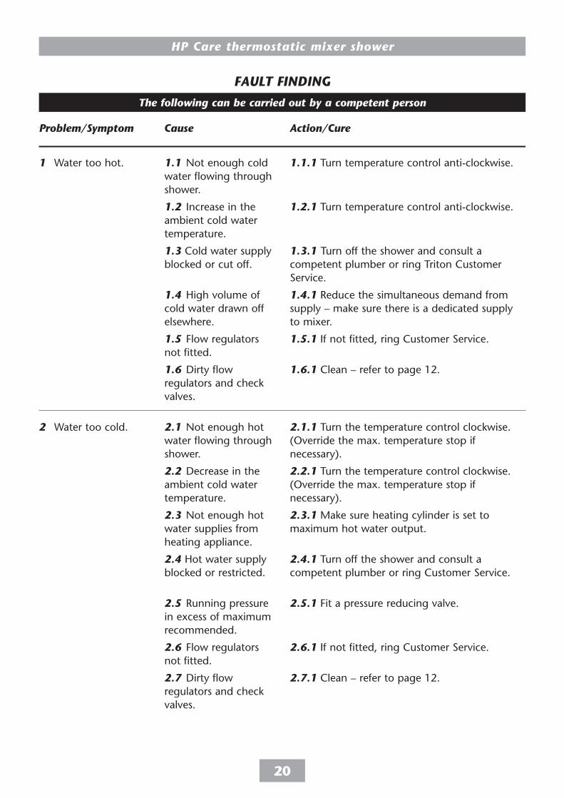
FAULT FINDING
FAULT FINDING
Problem/Symptom Cause Action/CureFAULT FINDING
Problem/Symptom Cause Action/Cure
The following can be carried out by a competent person
1.1 Not enough cold water flowing through shower.
1.2 Increase in the ambient cold water temperature.
1.3 Cold water supply blocked or cut off.
1.4 High volume of cold water drawn off elsewhere.
1.5 Flow regulators not fitted.
1.6 Dirty flow regulators and check valves.
2.1 Not enough hot water flowing through shower.
2.2 Decrease in the ambient cold water temperature.
2.3 Not enough hot water supplies from heating appliance.
2.4 Hot water supply blocked or restricted.
2.5 Running pressure in excess of maximum recommended.
2.6 Flow regulators not fitted.
2.7 Dirty flow regulators and check valves.
1.1.1 Turn temperature control anti-clockwise.
1.2.1 Turn temperature control anti-clockwise.
1.3.1 Turn off the shower and consult a competent plumber or ring Triton Customer Service.
1.4.1 Reduce the simultaneous demand from supply – make sure there is a dedicated supply to mixer.
1.5.1 If not fitted, ring Customer Service.
1.6.1 Clean – refer to page 12.
2.1.1 Turn the temperature control clockwise. (Override the max. temperature stop if necessary).
2.2.1 Turn the temperature control clockwise. (Override the max. temperature stop if necessary).
2.3.1 Make sure heating cylinder is set to maximum hot water output.
2.4.1 Turn off the shower and consult a competent plumber or ring Customer Service.
2.5.1 Fit a pressure reducing valve.
2.6.1 If not fitted, ring Customer Service.
2.7.1 Clean – refer to page 12.
1 Water too hot.
2 Water too cold.

HP Care thermostatic mixer shower
21
The following is recommended for a professional qualified installer only
3 Water does not flow or shower pattern collapses when another outlet is turned on.
4 Shower controls noisy when in use.
5 Shower will not shut off.
3.1.1 Check water elsewhere in house and if necessary contact local water company.
3.2.1 Inspect the flow regulators (if fitted) and the check valves – refer to page 12. Clean if necessary.
3.3.1 Turn off the shower and consult a competent plumber.
3.4.1 Clean showerhead.
3.5.1 Reduce the simultaneous demand – make sure there is a dedicated supply to mixer. 3.5.2 Make sure service valves are fully open. 3.5.3 Check if enough mains pressure.
4.1.1 Fit a pressure reducing valve.
5.1.1 Renew cartridge (internal seals are not serviceable).
3.1 Water supplies cut off.
3.2 Shower unit blocked.
3.3 Blockage in pipework.
3.4 Showerhead blocked.
3.5 System not capable of supplying multiple outlets at the same time.
4.1 Running pressure in excess of maximum recommended.
5.1 Pipework not flushed before connecting the unit (‘O’ rings damaged).
FAULT FINDING
Problem/Symptom Cause Action/Cure
Y-004-AAny maintenance or repair to the shower must be carried out by a suitablyqualified person
Triton Showers Triton Road Nuneaton Warwickshire CV11 4NR
Triton is a division of Norcros Group (Holdings) Limited
TRITON reserve the right to change product specification without prior notice. E&OA. © TRITON SHOWERS 2008
Service PolicyIn the event of a complaint occurring, the following procedure should be followed:1 Telephone Customer Service on
0870 067 3333 (0845 762 6591 in Scotland and in Northern Ireland), having available the model number and power rating of the product, together with the date of purchase.
2 Triton Customer Service will be able to confirm whether the fault can be rectified by either the provision of a replacement part or a site visit from a qualified Triton service engineer.
3 If a service call is required the unit must be fully installed for the call to be booked and the date confirmed. In order to speed up your request, please have your postcode available when booking a service call.
4 It is essential that you or an appointed representative (who must be a person of 18 years of age or more) is present during the service engineer's visit and receipt of purchase is shown.
5 A charge will be made in the event of an aborted service call by you but not by us, or where a call under the terms of guarantee has been booked and the failure is not product related (i.e. scaling and furring, incorrect water pressure).
6 If the product is no longer covered by the guarantee, a charge will be made for the site visit and for any parts supplied.
7 Service charges are based on the account being settled when work is complete, the engineer will then request payment for the invoice. If this is not made to the service engineer or settled within ten working days, an administration charge will be added.
Replacement Parts PolicyAvailability: It is the policy of Triton to maintain
availability of parts for the current range of products for supply after the guarantee has expired. Stocks of spare parts will be maintained for the duration of the product’s manufacture and for a period of five years thereafter.
In the event of a spare part not being available a substitute part will be supplied.
Payment: The following payment methods can be used to obtain spare parts:
1 By post, pre-payment of pro forma invoice by cheque or money order.
2 By telephone, quoting credit card (MasterCard or Visa) details.
3 By website order, www.tritonshowers.co.uk
TRITON STANDARD GUARANTEETriton guarantee this product against all mechanical defects arising from faulty workmanship or materials for a period of three years for domestic use only, from the date of purchase, provided that it has been installed by a competent person in full accordance with the fitting instructions.Any part found to be defective during this guarantee period we undertake to repair or replace at our option without charge so long as it has been properly maintained and operated in accordance with the operating instructions, and has not been subject to misuse or damage.This product must not be taken apart, modified or repaired except by a person authorised by Triton. This guarantee applies only to products installed within the United Kingdom and does not apply to products used commercially. This guarantee does not affect your statutory rights.
What is not covered:1 Breakdown due to: a) use other than domestic
use by you or your resident family; b) wilful act or neglect; c) any malfunction resulting from the incorrect use or quality of water or incorrect setting of controls; d) faulty installation.
2 Repair costs for damage caused by foreign objects or substances.
3 Total loss of the product due to non-availability of parts.
4 Compensation for loss of use of the product or consequential loss of any kind.
5 Call out charges where no fault has been found with the appliance.
6 The cost of repair or replacement of showerheads, hoses, riser rails and/or wall brackets or any other accessories installed at the same time.
7 The cost of routine maintenance, adjustments, overhaul modifications or loss or damage arising therefrom, including the cost of repairing damage, breakdown, malfunction caused by corrosion, furring, pipe scaling, limescale, system debris or frost.
Customer Service: % 0870 067 3333
Scottish and Northern Ireland Customer Service: % 0845 762 6591
Trade Installer Hotline: % 0870 067 3767 Fax: 0870 067 3334
www.tritonshowers.co.uk
E mail: [email protected]