Temperature and load-ratio dependent fatigue-crack growth ...
27
Accepted Manuscript Temperature and load-ratio dependent fatigue-crack growth in the CrMnFeCoNi high- entropy alloy Keli V.S. Thurston, Bernd Gludovatz, Qin Yu, Guillaume Laplanche, Easo P. George, Robert O. Ritchie PII: S0925-8388(19)31522-1 DOI: https://doi.org/10.1016/j.jallcom.2019.04.234 Reference: JALCOM 50418 To appear in: Journal of Alloys and Compounds Received Date: 20 February 2019 Revised Date: 19 April 2019 Accepted Date: 23 April 2019 Please cite this article as: K.V.S. Thurston, B. Gludovatz, Q. Yu, G. Laplanche, E.P. George, R.O. Ritchie, Temperature and load-ratio dependent fatigue-crack growth in the CrMnFeCoNi high-entropy alloy, Journal of Alloys and Compounds (2019), doi: https://doi.org/10.1016/j.jallcom.2019.04.234. This is a PDF file of an unedited manuscript that has been accepted for publication. As a service to our customers we are providing this early version of the manuscript. The manuscript will undergo copyediting, typesetting, and review of the resulting proof before it is published in its final form. Please note that during the production process errors may be discovered which could affect the content, and all legal disclaimers that apply to the journal pertain.
Transcript of Temperature and load-ratio dependent fatigue-crack growth ...

Accepted Manuscript
Temperature and load-ratio dependent fatigue-crack growth in the CrMnFeCoNi high-entropy alloy
Keli V.S. Thurston, Bernd Gludovatz, Qin Yu, Guillaume Laplanche, Easo P. George,Robert O. Ritchie
PII: S0925-8388(19)31522-1
DOI: https://doi.org/10.1016/j.jallcom.2019.04.234
Reference: JALCOM 50418
To appear in: Journal of Alloys and Compounds
Received Date: 20 February 2019
Revised Date: 19 April 2019
Accepted Date: 23 April 2019
Please cite this article as: K.V.S. Thurston, B. Gludovatz, Q. Yu, G. Laplanche, E.P. George, R.O.Ritchie, Temperature and load-ratio dependent fatigue-crack growth in the CrMnFeCoNi high-entropyalloy, Journal of Alloys and Compounds (2019), doi: https://doi.org/10.1016/j.jallcom.2019.04.234.
This is a PDF file of an unedited manuscript that has been accepted for publication. As a service toour customers we are providing this early version of the manuscript. The manuscript will undergocopyediting, typesetting, and review of the resulting proof before it is published in its final form. Pleasenote that during the production process errors may be discovered which could affect the content, and alllegal disclaimers that apply to the journal pertain.

MANUSCRIP
T
ACCEPTED
ACCEPTED MANUSCRIPT
Temperature and load-ratio dependent fatigue-crack growth in the
CrMnFeCoNi high-entropy alloy
Keli V. S. Thurstona,b, Bernd Gludovatzc, Qin Yua, Guillaume Laplanched,
Easo P. Georgee,f and Robert O. Ritchiea,b,*
aMaterials Sciences Division, Lawrence Berkeley National Laboratory, Berkeley, California 94720, USA bDepartment of Materials Science & Engineering, University of California, Berkeley, California, 94720, USA cSchool of Mechanical and Manufacturing Engineering, UNSW Sydney, NSW 2052, Australia dInstitut für Werkstoffe, Ruhr-Universität Bochum, D-44801, Bochum, Germany eMaterials Science and Technology Division, Oak Ridge National Laboratory, Oak Ridge, Tennessee 37831, USA fDepartment of Materials Science and Engineering, University of Tennessee, Knoxville, Tennessee 37996, USA
*Corresponding author ([email protected])
ABSTRACT
Multiple-principal element alloys known as high-entropy alloys have rapidly been gaining
attention for the vast variety of compositions and potential combinations of properties that
remain to be explored. Of these alloys, one of the earliest, the ‘Cantor alloy’ CrMnFeCoNi,
displays excellent damage-tolerance with tensile strengths of ~1 GPa and fracture toughness
values in excess of 200 MPa√m; moreover, these mechanical properties tend to further improve
at cryogenic temperatures. However, few studies have explored its corresponding fatigue
properties. Here we expand on our previous study to examine the mechanics and mechanisms
of fatigue-crack propagation in the CrMnFeCoNi alloy (~7 µm grain size), with emphasis on
long-life, near-threshold fatigue behavior, specifically as a function of load ratio at temperatures
between ambient and liquid-nitrogen temperatures (293 K to 77 K). We find that ΔKth fatigue
thresholds are decreased with increasing positive load ratios, R between 0.1 and 0.7, but are
increased at decreasing temperature. These effects can be attributed to the role of roughness-
induced crack closure, which was estimated using compliance measurements. Evidence of
deformation twinning at the crack tip during fatigue-crack advance was not apparent at
ambient temperatures but seen at higher stress intensities (ΔK ~ 20 MPa√m) at 77 K by post
mortem microstructural analysis for tests at R = 0.1 and particularly at 0.7. Overall, the fatigue
behavior of this alloy was found to be superior, or at least comparable, to conventional
cryogenic and TWIP steels such as 304L or 316L steels and Fe-Mn steels,; these results coupled
with the remarkable strength and fracture toughness of the Cantor alloy at low temperatures
indicate significant promise for the utility of this material for applications at cryogenic
environments.

MANUSCRIP
T
ACCEPTED
ACCEPTED MANUSCRIPT
Keywords: High-entropy alloys; fatigue; crack propagation; temperature effects; load ratio; crack closure
1. Introduction
The notion of multiple-principal element alloys, specifically high-entropy alloys (HEAs),
continues to captivate the structural materials community with the potential of innumerable
new metallic alloys with a broad range of structural properties yet to be investigated [1-9]. In
contrast to conventional alloy systems which invariably contain one, or two, principal elements,
such as iron in steel or nickel in certain superalloys, HEAs were originally defined with a
nominally equiatomic composition where the configuration entropy associated with at least five
base elements was presumed to overwhelm the enthalpy of phase formation to create a
(meta)stable solid solution [4,8,10]. Although more recent studies have since disputed this claim,
the nomenclature has stayed and represents a highly active field of endeavor as new
compositions are discovered [8,11-13].
A particularly notable HEA is the transition metal-based ‘Cantor alloy’ CrMnFeCoNi, a
single-phase, face-centered cubic (fcc) solid-solution alloy which displays exceptional
mechanical properties [2,11,14]. This alloy shows tensile strengths upwards of ~ 1 GPa, tensile
ductilities of ~60 to 70%, and high fracture toughness values exceeding 200 MPa√m, which are
further enhanced at cryogenic temperatures [14-17], properties that are comparable to, or exceed,
those of cryogenic steels [15-18].
While the uniaxial tensile and toughness properties of CrMnFeCoNi and other high-
entropy alloys are now well characterized [1-18], corresponding studies on the fatigue
properties are sparse, despite the fact that potential applications of these alloys as future
structural materials will invariably depend upon their fatigue resistance, which dictates
component lifetimes. Prior work on the Cantor alloy has provided measurements of the high-
cycle fatigue behavior of recrystallized CrMnFeCoNi at a single load ratio at 293 and 198 K [19]
whereas other studies on cast Al-containing CrCoNi-based variants have focused on stress-life
and crack propagation behavior [20,21]. These studies, while limited to ambient temperature
testing conditions, have observed fatigue behavior comparable or superior to steels and other

MANUSCRIP
T
ACCEPTED
ACCEPTED MANUSCRIPT
conventional alloys under both total-life and damage-tolerant fatigue testing, although this
behavior may in part be attributed to their as-cast microstructures [20].
In the current work, we seek to extend our understanding of the fatigue behavior of these
alloys and build upon our initial foundation [19] to further evaluate the near-threshold and
fatigue-crack propagation behavior of polycrystalline CrMnFeCoNi under a broader range of
conditions, specifically a range of load ratios with further cryogenic studies at 198 K and 77 K.
2. Experimental procedures
2.1. Mechanical testing
High-purity elemental constituents in near-equiatomic proportions were vacuum
induction melted and cast to form a 40 mm diameter cylindrical ingot of CrMnFeCoNi. Once
cast, the ingot was sealed in a silica casing and thermally homogenized at 1473 K for 48 hr. The
ingot was then rotary swaged at room temperature to a final diameter of ~16.5 mm and
recrystallized at 1073 K for 1 hr, yielding a final grain size of 7 ± 3 µm with a random orientation
distribution [21]. The bulk material was then cut into disc-shaped compact tension (DC(T))
samples in accordance with ASTM Standard E1820 through electric discharge machining (EDM).
Twenty-two samples were machined with the following dimensions: width W = 12.4 mm,
thickness B = 6 mm, and initial notch length ao = 3.6 mm with approximate notch root radii of
~100 µm, thus corresponding to an initial ao/W ratio of ~0.28.
Once cut, the samples were manually polished using metallographic silicon carbide paper
to a 1-µm mirror finish to allow for optical crack-length measurement. For continual monitoring
of the crack-growth rate during testing, a linear patterned strain gauge (Vishay Precision Group,
Raleigh, NC, USA) was used on the back-face of each specimen; model EA-06-031DE-350
gauges were used for tests at 293 K or 198 K and model WK-13-031DE-350 gauges at 77 K; the
latter to permit accurate readings in the deep-cryogen environment. Crack lengths were
calculated from the strain gauge readings of the elastic unloading portion of each cycle using

MANUSCRIP
T
ACCEPTED
ACCEPTED MANUSCRIPT
the compliance expression for the DC(T) sample with back-face strain, as described by Ritchie et
al. [23]:
a/W = 0.796239 + 5.40205u - 103.821u2 + 714.676u3 - 2603.44u4 + 4829.01u5 - 3578.51u6 , ( 1 )
where u = �
√������� . ( 2 )
Here E corresponds to the Young's modulus of the material, and C represents the compliance
calculated as the reciprocal from the unloading slope of the samples during testing. All testing
was conducted within the stated range of measurement validity of 0.3 ≤ a/W ≤ 0.8. The strain
gauges were calibrated and balanced at zero load and checked for measurement accuracy
throughout the pre-cracking stage using optical microscopy techniques to verify and calibrate
the system to ensure the calculated crack length accurately reflected the actual crack length.
Sinusoidal cyclic fatigue loading (tension-tension) was conducted using an electro-servo
hydraulic MTS 810 testing machine (MTS Corporation, Eden Prairie, MN, USA) controlled by
an Instron 8800 digital controller (Instron Corporation, Norwood, MA, USA). Prior to testing, all
samples were fatigue pre-cracked in accordance with ASTM Standard E647 [24] at ambient
temperature at a frequency 25 Hz (sine wave) under constant cyclic loading over a stress-
intensity range ΔK = 11 to 2 MPa√m, where ΔK = Kmax - Kmin, and the load ratio, the ratio of
minimum load to maximum load, ranged from R = 0.1 to 0.7. Between pre-cracking steps, the
crack path was visually checked for linearity and measured on both sides of the samples to
ensure even and valid crack growth. Including notch, the final pre-crack lengths ranged from ao
~3.9 to 4.2 mm (a/W ~ 0.31-0.34), as per standard requirements [24].
All fatigue-crack propagation testing was performed under load-shedding or constant
load control conditions at a constant load ratio. Near-threshold testing was performed under
load-shedding conditions in which the controller was automated to decrease the imposed load
at a rate such that the normalized K-gradient remained above -0.08 mm-1, as recommended in
ASTM E647 [24]. The value of the ∆Kth fatigue threshold stress-intensity range was determined
to be at the value of ∆K at which the growth rates were less than 10-11 m/cycle. Higher crack
growth rates were characterized under constant load conditions, in which the amplitude of the

MANUSCRIP
T
ACCEPTED
ACCEPTED MANUSCRIPT
alternating load was held constant, effectively increasing the stress-intensity range as the crack
grew.
Fatigue-crack propagation testing, over the range 10-11 to 10-7 m/cycle, was performed at 25
Hz at temperatures of 293 K, 198 K and 77 K at load ratios of R = 0.1, 0.4 and 0.7. Tests at the two
cryogenic temperatures were performed with immersion baths of liquid nitrogen and
ethanol/dry-ice for 77 K and 198 K, respectively, with sufficient time allowed for sample and
strain gauge temperatures to equilibrate with the environment before the start of testing. The
293 K testing was performed in air under ambient laboratory conditions. All tests were
performed continuously without interruption once started to maintain conditions and avoid
any thermal cycling effects. Data are presented as log-log plots of the fatigue-crack growth rates
da/dN as a function of ∆K, following a nominal Paris power-law formulation [25] where da/dN ∝
∆Km, where m is the Paris law exponent (typically measured in the mid-range of growth rates,
i.e., in this alloy above 10-9 m/cycle).
Near-threshold test specimens were further subjected to loading and unloading to
estimate the extent of crack closure, Kcl, i.e., the physical contact of the mating fracture surfaces,
the crack experiences in the wake of the tip upon unloading of the sample. To measure closure
for each sample, the sample was loaded uniaxially to a load corresponding to the maximum
load at the threshold, and then unloaded to a load corresponding to the minimum loading with
the resulting load-displacement curve recorded. These full loading-unloading cycles were
repeated 5 times. The point at which the slope of the unloading curve changes was identified as
the point at which the crack is closed as the fracture surfaces come into contact. As with most
quantitative estimates of closure, this technique is approximate; however, the analysis was used
to determine an approximate effective stress-intensity range actually experienced at the crack
tip, where ∆Keff = Kmax - Kcl, and where Kcl > Kmin; where Kcl < Kmin, ∆Keff = ∆K. Full details of these
procedures can be found elsewhere [26,27]. The loading cycles were performed, at each of the
three test temperatures, in incremental steps corresponding to an increase in ΔK of 0.5 MPa√m
beginning at the threshold of the respective sample and the resultant load-displacement curves
were plotted as described below.

MANUSCRIP
T
ACCEPTED
ACCEPTED MANUSCRIPT
2.2. Fractographic characterization
At the conclusion of the mechanical testing, fractographical analysis was performed to
characterize the nature and mechanisms involved in crack propagation under the various
conditions. Fracture surface characterization was performed on samples fatigued in tension to
overload to expose the surface while maintaining surface features. Imaging was conducted in
secondary electron (SE) modes of a FEI Strata DB235 SEM (FEI Company, Hillsboro, OR, USA)
and a JSM-7500F SEM (JEOL USA, Arvada, CO, USA) operated at 5-15 kV.
To specifically examine the crack path and the deformation mechanisms, in particular the
occurrence of deformation twinning, in the frontal plastic zone and its wake, where the plastic-
zone size, ry, was estimated as 1/2π (Kmax/σy)2 where σy is the yield strength, each fatigue tested
DC(T) sample was longitudinally sliced into two metallurgical samples at the mid-plane
section, and subsequently ground and polished sequentially using 1 µm polycrystalline
diamond suspension and then a 0.05 µm alumina suspension. The final surface was analyzed
using back-scattered electron (BSE) imaging and electron backscatter diffraction (EBSD)
imaging was conducted after vibration polishing for 12 hr with the sample surface emerged in
colloidal silica suspension. SE and BSE imaging were conducted by using a Hitachi S-4300SE/N
scanning electron microscope, SEM (Hitachi America, Pleasanton, CA) operated at 10 kV. EBSD
scans were performed along the crack path and in the vicinity of the crack tip on the polished
mid-plane sections using the FEI Strata DB235 SEM operated at 20 kV using a TEAMTM EDAX
analysis system (Ametek EDAX, Mahwah, NJ, USA). The SEM was equipped with an
Orientation Imaging Microscopy (OIM) system (Ametek EDAX, Mahwah, NJ, USA), which
enabled image post-processing using OIM Analysis v7 software. To specifically detect nano-
twins, EBSD data were collected with the finest step size of 18 nm.
3. Results
While many metallic materials experience a degradation in damage-tolerance at low
temperatures, the CrMnFeCoNi notably displays an increase in tensile strength and ductility
[11,14,16,17]. Our previous fatigue-crack propagation studies on this alloy conducted at low

MANUSCRIP
T
ACCEPTED
ACCEPTED MANUSCRIPT
load ratios (R = 0.1) noted a similar improvement of fatigue properties, specifically fatigue-crack
propagation properties, as the temperature was lowered, which was particularly evident in the
near-threshold regime [19]. In the present study, we extended the measurement of fatigue-crack
propagation rates and ∆Kth threshold stress-intensity data down to 77 K and explicitly examined
the role of load ratio. A plot of all collected fatigue-crack propagation data as a function of the
stress-intensity range for the Cantor alloy is shown in Figure 1; specific parameters measured
from the data are listed in Table 1.
3.1. Fatigue-crack growth behavior
From Fig. 1 and Table 1, it can be seen that over the mid-range of growth rates above ~10-9
m/cycle, the Paris law exponents for all temperatures and load ratios were largely in the
characteristic range of m ~ 2 to 4, although in general there was a marked trend of increasing
fatigue-crack growth resistance, i.e., lower growth rates, at a given ∆K, and higher values of the
fatigue ∆Kth thresholds, at the lower temperatures. Indeed, threshold ∆Kth values, which ranged
from 6.3 to 2.5 MPa√m at load ratios between 0.1 and 0.7, were respectively 31% and 12% higher
at 198 K than at 293 K (Fig. 2). As discussed elsewhere [19], such fatigue-crack growth rates in
this high-entropy alloy are comparable to that of traditional metallic alloys with tensile
strengths of the order of 1 GPa (for an extended discussion, see ref. [19]).
Additionally, we found a marked effect of increasing fatigue-crack growth rates with
increasing load ratios, which became more prominent at near-threshold levels. Specifically, ∆Kth
threshold values, in particular, were lower at increasing R; in fact, ∆Kth values were 2-3 times
lower at R = 0.7 compared to R = 0.1 (Fig. 2). Such load-ratio dependent behavior is typical of
most metallic alloys [25] and can generally be related to crack-tip shielding from fatigue crack
closure effects [27-29], as discussed below.
It should also be noted that based on da/dN ∝ ∆CTOD ∝ ∆K2/σyE, where CTOD is the
crack-tip opening displacement, when σy is only weakly dependent on temperature, as in pure
fcc metals, da/dN values for a given ∆K can be assumed to be similar at high R-ratios where crack
closure can essentially be neglected. In our material, however, the differences in growth rates
between room and liquid nitrogen temperatures, e.g., at a ∆K of 5 MPa√m, the crack growth rate

MANUSCRIP
T
ACCEPTED
ACCEPTED MANUSCRIPT
at R = 0.7 at 77K is approximately 1x10⁻⁹ m/cycle, whereas at 293K it is approximately 2x10⁻⁹
m/cycle (see Fig. 1), is likely associated with changes in σy, and to a lesser extent E, between
these two temperatures.
3.2. Threshold and crack closure analysis
The most prevalent reason for the marked effect of load ratio on fatigue-crack growth
rates, especially at near-threshold levels, is that of crack closure. As this phenomenon is
dominated by shielding effects due to wedging between the crack flanks, e.g., from corrosion
debris (oxide-induced crack closure) and/or from crack surface asperities (roughness-induced
crack closure), which act to reduce the effective stress-intensity range actually experienced at the
crack tip, crack closure is exacerbated at low ∆K levels, where the crack-tip opening
displacements (CTODs) are small and become comparable in dimension to the thickness of the
“wedge”, yet minimized at high positive load ratios where the minimum opening
displacements are much larger, specifically where Kmin > Kcl [28]. On the simple assumption that
the value of the closure stress intensity Kcl, and the effective stress intensity range at the
threshold ∆Keff,th are nominally constant and independent of R, we would expect the measured
variation in ∆Kth thresholds to follow “Schmidt & Paris type” behavior [29]. Specifically, below a
critical load ratio where Kcl = Kmin (this is typically of the order of R ~ 0.4-0.5), the ∆Kth threshold
should decrease with increasing R whereas the threshold Kmax should remain roughly constant
(this is the regime where closure is active as Kcl > Kmin); above this critical R value though (where
closure is inactive as Kcl < Kmin), the value of ∆Kth threshold should reach a lower-bound “plateau”
whereas the Kmax,th threshold should increase as R tends to unity. This type of variation in
fatigue threshold values and how it relates to the presence of crack closure phenomena is
described in further detail in ref. [30]. Although we have only tested three different load ratios
at each temperature, our threshold measurements for this high-entropy alloy are not
inconsistent with this hypothesis, as shown in Fig. 2.
Comparison of these ∆Kth fatigue thresholds with those in steels and other engineering
metallic alloys at comparable strength levels [26-31] suggests that the values measured in this
study, and previously [19], for the CrMnFeCoNi HEA are comparable in magnitude.

MANUSCRIP
T
ACCEPTED
ACCEPTED MANUSCRIPT
To provide some quantitative evidence for these explanations for the variation in fatigue
thresholds in the Cantor alloy based on crack closure, Kcl closure stress intensities that were
measured at near-threshold levels on samples tested at 293 K and 198 K, are summarized in
Table 1. It is evident that crack closure levels are far higher at low load ratios, as expected.
Moreover, the effective ∆Keff,th thresholds appear to be roughly constant, again consistent with
our observations of the marked effect of load ratio on the near-threshold fatigue behavior being
associated with a crack closure effect. With regards to the trends in fatigue properties with
temperature, the data show that crack closure is observed at R = 01 and 0.4 but not at R = 0.7 in
samples tested at 198 K. In both temperature ranges, crack closure appears to play a major role
in the near-threshold fatigue behavior of this alloy.
However, pertinent questions that remain are whether this closure effect can be associated
with fracture surface roughness, which is the most ubiquitous form of fatigue crack closure in
metallic materials, whether such phenomena can explain the observed increase in ∆Kth
thresholds in this HEA at cryogenic temperatures, and whether deformation twinning, which is
so prevalent during overload fracture in this alloy at 77 K [16,17], may play an active role
during fatigue-crack growth. To investigate these issues, we investigate crack trajectories and
corresponding fracture surface morphologies, as described below.
3.3. Fractography
Fractography was performed using scanning electron microscopy on the fracture surfaces
of representative samples. Images depicting regions at approximately ∆K ~ 12 MPa√m are
shown in Fig. 3 and are oriented with the general crack propagation direction from the top to
the bottom of the micrographs. For tests at low load ratios, a transition from transgranular to
intergranular fracture behavior, from relatively smooth fracture surfaces to coarser, facet-like
features, was seen for the lower crack-growth rates as the temperature was reduced from 293 K
to 198 K [19]. This intergranular behavior is particularly visible in Figs. 3b and 3e, in which the
feature sizes of the facet-like structures correspond to some small fraction of the grain size,
suggesting a fracture path along the grain boundaries at 198 K; in contrast, the corresponding
293 K fracture surfaces, imaged Figs. 3c and 3f, show much smaller, more irregular surface
MANUSCRIP
T
ACCEPTED
ACCEPTED MANUSCRIPT
features that may correspond to slip or other plastic fracture behavior. Such behavior, which
purports that the fatigue fracture surfaces become rougher at the lower temperature, is
consistent with the higher measured closure values and our observations of higher ∆Kth
thresholds at 198 K as compared to 293 K as demonstrated in Fig. 1. This general trend is
observed to continue as the temperature is lowered further to 77 K as shown in Fig. 3, though
the facets are somewhat more obscured. Together, these images depict a greater degree of
plastic deformation within samples subject to comparable stress intensities at higher
temperatures and, especially at lower ∆K levels, to a rougher, more faceted, intergranular
fracture mode at cryogenic temperatures. Additionally, with increasing ∆K levels, especially as
the R-ratio is increased, evidence of local cyclic plasticity, e.g., in the form of markedly visible
fatigue striations (Fig. 4), becomes more prominent.
As with many metallic alloys [26-28], one may conclude that the influence of both
temperature and load ratio on fatigue-crack propagation behavior in this alloy likely result
primarily from closure effects, principally motivated by such fracture surface roughness. By
promoting premature contact of the crack surfaces due to their rough morphology during the
unloading cycle, roughness-induced crack closure acts to increase the effective minimum stress
intensity, thereby reducing the effective stress-intensity range actually experienced at the crack
tip. Such roughness has a larger effect at near-threshold levels, where the cyclic crack-tip
opening displacements ∆CTODs (~∆K2/2σyE) are smaller, which on the basis of our Kcl
measurements (Table 1) appears to account for the higher ∆Kth thresholds at lower temperatures.
Furthermore, the closure concept is consistent with the lesser effect of temperature on ∆Kth
thresholds at high load ratios, where the maximum CTODs are far larger, as shown in Table 1.
This represents the generally accepted reason for the decrease in ∆Kth thresholds with increasing
R [28-30].
3.4. Crack path studies
To further investigate the potential deformation mechanisms at play during fatigue-crack
growth in the Cantor alloy, EBSD imaging was performed along the central (mid-thickness)
cross-section of fatigued samples, with a particular focus on the crack path and the presence, or

MANUSCRIP
T
ACCEPTED
ACCEPTED MANUSCRIPT
absence, of deformation nano-twins in the strained regions in the vicinity of the crack tip. Nano-
twinning has been identified as a prime mechanism associated with the exceptional toughness
of this alloy at cryogenic properties with a greater propensity to occur at higher strains and
lower temperatures where strength levels are higher [16,17]; there is little evidence of such
twinning during deformation in CrMnFeCoNi at ambient temperatures, except at high strains
just prior to fracture. As no evidence of twinning during fatigue-crack growth was seen at ΔK
levels less than 10 MPa√m for temperatures at or above 198 K in our previous study [19], we
sought here to extend these observations down to 77 K and to higher stress-intensity ranges at
higher load ratios (to maximize the local crack-tip stresses).
BSE and EBSD images in Fig. 5 show the microstructure features taken in the crack-tip
region at 77 K under R = 0.1 and R = 0.7 with ΔK levels of 29 MPa√m and 20 MPa√m,
respectively (corresponding Kmax values at R = 0.1 and 0.7 were 32 and 67 MPa√m). Here, the
entire imaged region may be presumed to have experienced deformation, due to the large size
of the maximum plastic zone ry, which was approximately ~287 µm and ~1.23 mm, respectively
at these two R = 0.1 and 0.7 loading conditions.
As revealed in BSE and EBSD images, fatigue-crack propagation at both R-ratios is
largely transgranular at higher ∆K levels with an increasing incidence of rougher, more facetted,
intergranular-type fracture at lower, near-threshold levels. BSE scans reveal the formation of
dislocation cells and deformation nano-twins in the wake of the propagated crack within a
region of 1~3 grains. Most importantly, EBSD inverse pole figure (IPF) maps overlaid with
image quality (IQ) maps1 confirm the presence of the deformation-induced nano-twinning
during fatigue cracking at 77 K [1].2 This conclusion is further verified by the line scans across
the twin boundaries, showing a typical 60° misorientation between the twin domain and the
parent grain domain. Compared to crack growth at R = 0.1, the nano-twins and dislocation cells
associated with crack growth at R = 0.7 are more pronounced, with the thickness of the
1 Image quality IQ maps measure the sharpness of the Kikuchi bands collected at each EBSD scan point [32]. They are useful in visualizing the microstructural features that cause poor band contrast, such as small pores/inclusions and phase/grain/twin boundaries. 2 Note that there is always evidence of a few annealing twins. However, these can be readily distinguished from deformation-induced nano-twins as the annealing twins are far larger with widths of several micrometers.
MANUSCRIP
T
ACCEPTED
ACCEPTED MANUSCRIPT
measurable nano-twins roughly 50% wider at R = 0.7 than at R = 0.1; this is likely due to the far
higher Kmax value of ~67 MPa√m. We conclude that deformation-induced nano-twinning is
active in the process of cyclic deformation during fatigue-crack propagation in the Cantor alloy
at liquid-nitrogen temperatures, although there is little evidence for this under ambient-
temperature conditions.
4. Discussion
The CrMnFeCoNi alloy, developed by Cantor and coworkers [2], is almost certainly the
most studied high-entropy alloy to date, principally because it has been shown to display
exceptional mechanical properties of high strength, ductility and fracture toughness, which are
all increased at cryogenic temperatures [3,14-17]. Although the mechanisms underlying such
behavior are complex involving a synergy of differing deformation processes [16,33], a prime
mechanism appears to involve the onset of deformation nano-twinning at lower temperatures
which serves to enhance strain hardening to promote strength and ductility, the latter by
delaying the onset of plastic instability or necking [14-17]. In light of this, it is of interest that we
show here that similarly the fatigue-crack propagation resistance, specifically the value of the
∆Kth fatigue threshold, is also increased at cryogenic temperatures in this alloy. However, this
effect, we believe, derives from a completely different mechanism, that of the enhancement of
(roughness-induced) crack closure at lower temperatures due to the onset of a rougher, more
facetted, intergranular fatigue fracture mode. Irrespective of the prevailing mechanisms though,
the damage-tolerant properties of the CrMnFeCoNi high-entropy alloy, with respect to both
subcritical cracking (fatigue) resistance and the crack-initiation and growth fracture toughnesses
at tensile strengths exceeding 1 GPa [14-19], are exceptional and comparable, or even exceed,
the best metallic structural materials reported to date. Indeed, the Cantor alloy shows
outstanding promise for numerous structural applications, particularly under cryogenic
conditions.
5. Conclusions

MANUSCRIP
T
ACCEPTED
ACCEPTED MANUSCRIPT
Based on an experimental study of fatigue-crack propagation in the equiatomic Cantor
high-entropy alloy, comprising a face-centered cubic CrMnFeCoNi solid solution with ~7 µm
grain size, as a function of load ratio (R = 0.1 to 0.7) at temperatures between 293 and 77 K, the
following conclusions can be made:
• In the mid-range of growth rates, above 10-9 m/cycle, the Paris power-law exponents for all
temperatures and load ratios were largely in the characteristic range of m ~ 2 to 4,
consistent with observations of fatigue striations. As noted previously, such fatigue-crack
growth behavior in this HEA is comparable to that of traditional metallic alloys with
tensile strengths of the order of 1 GPa.
• Fatigue-crack propagation resistance, in terms of lower growth rates at a given ∆K, and
higher values of the ∆Kth fatigue thresholds, was increased with decrease in temperature,
with the effect being progressively enhanced at near-threshold levels. Indeed, ∆Kth values,
which ranged from 6.3 to 2.5 MPa√m at load ratios between 0.1 and 0.7, were respectively
31% and 12% higher at 198 K than at 293 K. Again, these values are typical for traditional
metallic alloys at this strength range.
• Crack closure was found to occur during fatigue-crack growth, and was assessed using
compliance techniques in measurements of the closure stress intensity, Kcl. As measured
closure levels were higher at the lower temperatures, in accordance with crack wedging
due to a more facetted intergranular crack path, we believe that the more prominent
occurrence of this mode of crack-tip shielding was the main factor underlying the
increased fatigue resistance of this alloy at the lower temperatures. This conclusion is
consistent with observations that the beneficial effect of cryogenic temperatures was
enhanced at lower growth rates where the crack-tip opening displacements are smaller.
• Characteristic of most metallic materials, crack-growth rates were increased with increase
in load ratio, with the effect being more pronounced at progressively decreasing growth
rates. Indeed, for temperatures of 293 and 198K, values of the ∆Kth fatigue thresholds were
some 2 to 3 times higher at R = 0.1 than at R = 0.7. Again, such behavior was found to be
MANUSCRIP
T
ACCEPTED
ACCEPTED MANUSCRIPT
consistent with crack closure phenomena, principally due (at a given ∆K) to the larger
crack-tip opening displacements generated at high load ratios.
• Although not observed at ambient temperatures, evidence was found for cyclic
deformation-induced nano-twinning during fatigue-crack propagation in the
CrMnFeCoNi alloy at temperatures as low as 77 K and load ratios of 0.1 and 0.7.
Compared to R = 0.1, nano-twins were more pronounced and thicker at R = 0.7, likely due
to the much higher Kmax values under high R loading.
Acknowledgements
This study was conducted by the Mechanical Properties of Materials program (KC13) at
the Lawrence Berkeley National Laboratory (LBNL), supported by the U.S. Department of
Energy, Office of Science, Office of Basic Energy Sciences, Division of Materials Sciences and
Engineering under contract no. DE-AC02-05-CH11231. E.P.G. was also supported by the
Materials Sciences and Engineering Division of the Department of Energy, Office of Science,
Office of Basic Energy Sciences through the Materials Science and Technology Division at the
Oak Ridge National Laboratory. K.V.S.T. acknowledges salary support from a Natural Science
Foundation Graduate Fellowship, under NSF GRFP grant no. 1106400, and G.L. acknowledges
funding from the German Research Foundation (DFG) through project LA 3607/1-1. Electron
microscopy was carried out at LBNL’s Molecular Foundry supported by the Office of Science,
Office of Basic Energy Sciences, of the U.S. Department of Energy under contract no. DE-AC02-
05-CH11231.
References
[1] W. Li, P. K. Liaw, Y. Gao, Fracture resistance of high entropy alloys: a review, Intermetallics 99 (2018) 69-83, http://dx.doi.org/10.1016/j.intermet.2018.05.013.
[2] B. Cantor, I. T. H. Chang, P. Knight, A. J. B. Vincent, Microstructural development in equiatomic multicomponent alloys, Mater. Sci. Eng. A 375-377 (2004) 213-218, http://dx.doi.org/doi:10.1016/j.msea.2003.10.257.
[3] A. Gali, E. P. George, Tensile properties of high- and medium-entropy alloys, Intermetallics, 39 (2013) 74-78, http://dx.doi.org/10.1016/j.intermet.2013.03.018.
MANUSCRIP
T
ACCEPTED
ACCEPTED MANUSCRIPT
[4] J. W. Yeh, S. K. Chen, S. J. Lin, J. Y. Gan, T. S. Chin, T. T. Shun, C. H. Tsau, S. Y. Chang, Nanostructured high-entropy alloys with multiple principle elements: Novel alloy design concepts and outcomes, Adv. Eng. Mater. 6 (2004) 299-303, http://dx.doi.org/10.1002/adem.200300567.
[5] J. Chen, J. Chen, X. Zhou, W. Wang, B. Liu, Y. Lv, W. Yang, D. Xu, Y. Lu, A review on fundamental of high entropy alloys with promising high-temperature properties, J. Alloys Compd. 760 (2018) 15-30, http://dx.doi.org/10.1016/j.jallcom.2018.05.067.
[6] Y. F. Ye, Q. Wang, J. Lu, C. T. Liu, Y. Yang., High-entropy alloy: Challenges and prospects, Mater. Today 19 (6) (2016) 349-362, http://dx.doi.org/10.1016/j.mattod.2015.11.026.
[7] Y. Zhang, T. T. Zuo, Z. Tang, M. C. Gao, K. A. Dahman, P. K. Liaw, Z. P. Lu, Microstructures and properties of high-entropy alloys, Prog. Mater. Sci. 61 (2014) 1-93, http://dx.doi.org/10.1016/j.pmatsci.2013.10.001.
[8] E. J. Pickering, N. G. Jones, High-entropy alloys: A critical assessment of their founding principles and future prospects, Int. Mater. Rev. 61 (2016) 1743-2804, http://dx.doi.org/10.1080/09506608.2016.1180020.
[9] Z. Li, Z. S. Zhao, R. O. Ritchie, M. A. Meyers. Mechanical properties of high-entropy alloys with emphasis on face-centered cubic alloys. Progr. Mater. Sci. 102 (2019): 296–345. https://doi.org/10.1016/j.pmatsci.2018.12.003.
[10] J. W. Yeh, Physical metallurgy of high-entropy alloys, JOM 67 (2015) 2254-2261, http://dx.doi.org/10.1007/s11837-015-1583-5.
[11] F. Otto, Y. Yang, H. Bei, E. P. George, Relative effects of enthalpy and entropy on the phase stability of equatomic high-entropy alloys, Acta Mater. 61 (2013) 2628-2638, http://dx.doi.org/10.1016/j.actamat.2013.01.042.
[12] C. C. Tasan, Y. Deng, K. G. Pradeep, M. J. Yao, H. Springer, D. Raabe, Composition dependence of phase stability, deformation mechanisms, and mechanical properties of the CoCrFeMnNi high-entropy alloy system, JOM 66 (2014) 1993-2001, http://dx.doi.org/10.1007/s11837-014-1133-6.
[13] C. G. Schӧn, T. Duong, Y. Wang, R. Arróyave, Probing the entropy hypothesis in highly concentrated alloys, Acta Mater. 148 (2018) 263-279, http://dx.doi.org/10.1016/j.actamat.2018.01.028.
[14] B. Gludovatz, E. P. George, R. O. Ritchie, Processing, microstructure and mechanical properties of the CrMnFeCoNi high-entropy alloy, JOM 67 (2016) 2262-2270, http://dx.doi.org/10.1007/s11837-015-1589-z.

MANUSCRIP
T
ACCEPTED
ACCEPTED MANUSCRIPT
[15] S. J. Sun, Y. Z. Tien, H. R. Lin, H. J. Yang, X. G. Dong, Y. H. Wang, Z. F. Zhang, Achieving high ductility in the 1.7 GPa grade CoCrFeMnNi high-entropy alloy at 77 K, Mater. Sci. Eng. A 740-741 (2019) 336-341, http://dx.doi.org/10.1016/j.msea.2018.10.094.
[16] B. Gludovatz, A. Hohenwarter, D. Cartoor, E. H. Chang, E. P. George, R. O. Ritchie, A fracture-resistant high-entropy alloy for cryogenic applications, Science 345 (2014) 1153-1158, http://dx.doi.org/10.1126/science.1254581.
[17] F. Otto, A. Dlouhy, Ch. Somsen, H. Bei, G. Eggeler, E. P. George, The influences of temperature and microstructure on the tensile properties of CoCrFeMnNi high-entropy alloy, Acta Mater. 61 (2013) 5743-5755, http://dx.doi.org/10.1016/j.actamat.2013.06.018.
[18] N. Stepanov, M. Tikhonovsky, N. Yurchenko, D. Zyabkin, M. Klimova, S. Zherebtsov, A. Efimov, G. Salishchev, Effect of cryo-deformation on structure and properties of CoCrFeNiMn high-entropy alloy, Intermetallics 55 (2015) 8-17, http://dx.doi.org/10.1016/j.intermet.2014.12.004.
[19] K. V. S. Thurston, B. Gludovatz, A. Hohenwarter, G. Laplanche, E. P. George, R. O. Ritchie, Effect of temperature on the fatigue-crack growth behavior of the high-entropy alloy CrMnFeCoNi, Intermetallics 88 (2017) 65-72, http://dx.doi.org/10.1016/j.intermet.2017.05.009.
[20] M. Seifi, D. Li, Z. Yong, P. K. Liaw, J. J. Lewandowski, Fracture toughness and fatigue crack growth behavior of as-cast high-entropy alloy, JOM 67 (2015) 2288-2295, http://dx.doi.org/10.1007/s11837-015-1563-9.
[21] M. A. Hemphill, T. Yuan, G. Y. Wang, J. W. Yeh, C. W. Tsai, A. Chuang, P. K. Liaw, Fatigue behavior of Al0.5CoCrCuFeNi high entropy alloys, Acta Mater. 60(16) (2012) 5723-5734, http://dx.doi.org/10.1016/j.actamat.2012.06.046.
[22] G. Laplanche, O. Horst, F. Otto, G. Eggeler, E. P. George, Microstructural evolution of a CoCrFeMnNi high-entropy alloy after swaging and annealing, J. Alloys Compd. 647 (2015) 548-57, http://dx.doi.org/10.1016/j.jallcom.2015.05.129.
[23] C. J. Gilbert, J. M. McNaney, R. H. Dauskardt, R. O. Ritchie, Back-face strain compliance and electrical-potential crack length calibrations for the disk-shaped compact-tension DC(T) specimen, J. Test. Eval. 22 (1994) 117-120, http://dx.doi.org/10.1520/jte12644j.
[24] ASTM Standard E647, Standard test method for measurement of fatigue crack growth rates, ASTM International, West Conshohocken, PA (2013), www.astm.org.
[25] P. C. Paris, F. Erdogan, A critical analysis of crack propagation laws, ASME, J. Basic Eng. 85(4) (1963) 528-533, http://dx.doi.org/10.1115/1.3656900.
[26] R. O. Ritchie, W. Yu, Short crack effects in fatigue: A consequence of crack tip shielding, in Small Fatigue Cracks, R. O. Ritchie and J. Lankford, eds., TMS-AIME (1986) 167-189.

MANUSCRIP
T
ACCEPTED
ACCEPTED MANUSCRIPT
[27] K. T. Venkateswara Rao, W. Yu, R. O. Ritchie, Fatigue crack propagation in aluminum-lithium alloy 2090: Part 1: Long crack behavior, Metall. Mater. Trans. A 19A(3) (1988) 549-561, http://dx.doi.org/10.1007/BF02649269.
[28] R. O. Ritchie, Mechanisms of fatigue crack propagation in metals, ceramics and composites: Role of crack-tip shielding, Mater. Sci. Eng. A 103 (1988) 15-28, http://dx.doi.org/10.1016/0025-5416(88)90547-2.
[29] R. A. Schmidt, P. C. Paris, Threshold for fatigue crack propagation and effects of load ratio and frequency, in Progress in Crack Growth and Fracture Toughness Testing, ASTM STP 536 (1973) 79-94, American Society for Testing and Materials, Philadelphia, PA.
[30] B. L. Boyce, R. O. Ritchie, Effect of load ratio and maximum stress intensity on the fatigue threshold in Ti-6Al-4V, Eng. Fract. Mech. 68 (2001) 129-147, http://dx.doi.org/10.1016/S0013-7944(00)00099-0.
[31] R. O. Ritchie, Near-threshold fatigue crack propagation in steels, Intl. Metals Rev. 24 (1979) 205-230, http://dx.doi.org/10.1179/imtr.1979.24.1.205.
[32] R. A. Schwarzer, J. Sukkau, Electron back scattered diffraction: Current state, prospects and comparison with x-ray diffraction texture measurement, Banaras Metall., 18 (2013) 1-11.
[33] Z-J. Zhang, M. M. Mao, J. Wang, H. Tian, B. Gludovatz, Z. Zhang, S. X. Mao, E. P. George, Q. Yu, R. O. Ritchie, Nanoscale origins of the damage tolerance of the high-entropy alloy CrMnFeCoNi, Nature Comm. 6 (2015) 10143, https://doi.org/10.1038/ncomms10143.
Table 1. Summary of fatigue-crack growth, threshold values and crack closure measurements for the CrMnFeCoNi HEA, extracted from Figs. 1, 2.
Temp. Load Ratio
(R)
Paris Law exponent
(m)
Threshold (ΔKth)
[MPa√m]
CTODmax [nm]
Crack Closure (Kcl)
[MPa√m]
ΔKth,eff [MPa√m]
Plastic-zone size (ry)
[µm]
293 K
0.1 3.5 4.8 160 1.38 3.95 27
0.4 2.8 2.6 105 - 2.6 18
0.7 2.6 2.5 390 - 2.5 66
198 K 0.1 4.5 6.3 210 2.15 4.85 29
0.4 3.4 4.8 275 2.7 - 3.4 4.6 - 5.3 38

MANUSCRIP
T
ACCEPTED
ACCEPTED MANUSCRIPT
0.7 3.1 3.5 585 - 3.5 81
77 K
0.1 2.9
0.4 2.3
0.7 2.3

MANUSCRIP
T
ACCEPTED
ACCEPTED MANUSCRIPT
Figure 1. Fatigue-crack growth rates as a function of the stress-intensity range for the CrMnFeCoNi
HEA under various testing conditions. Testing was conducted over three temperature ranges between
ambient (293 K) and liquid-nitrogen temperature (77 K) at load ratios of R = 0.1, 0.4, and 0.7 at 25 Hz.
Tests at 77 K were limited to growth rates above the ~10-9 m/cycle regime, while testing at 293 K and 198
K was performed until the fatigue threshold stress intensity was reached. A direct comparison of the
crack-propagation curves characterizing these various testing parameters indicates an increase in the
value of the ∆Kth fatigue threshold as both temperature and load ratio were decreased.
MANUSCRIP
T
ACCEPTED
ACCEPTED MANUSCRIPT
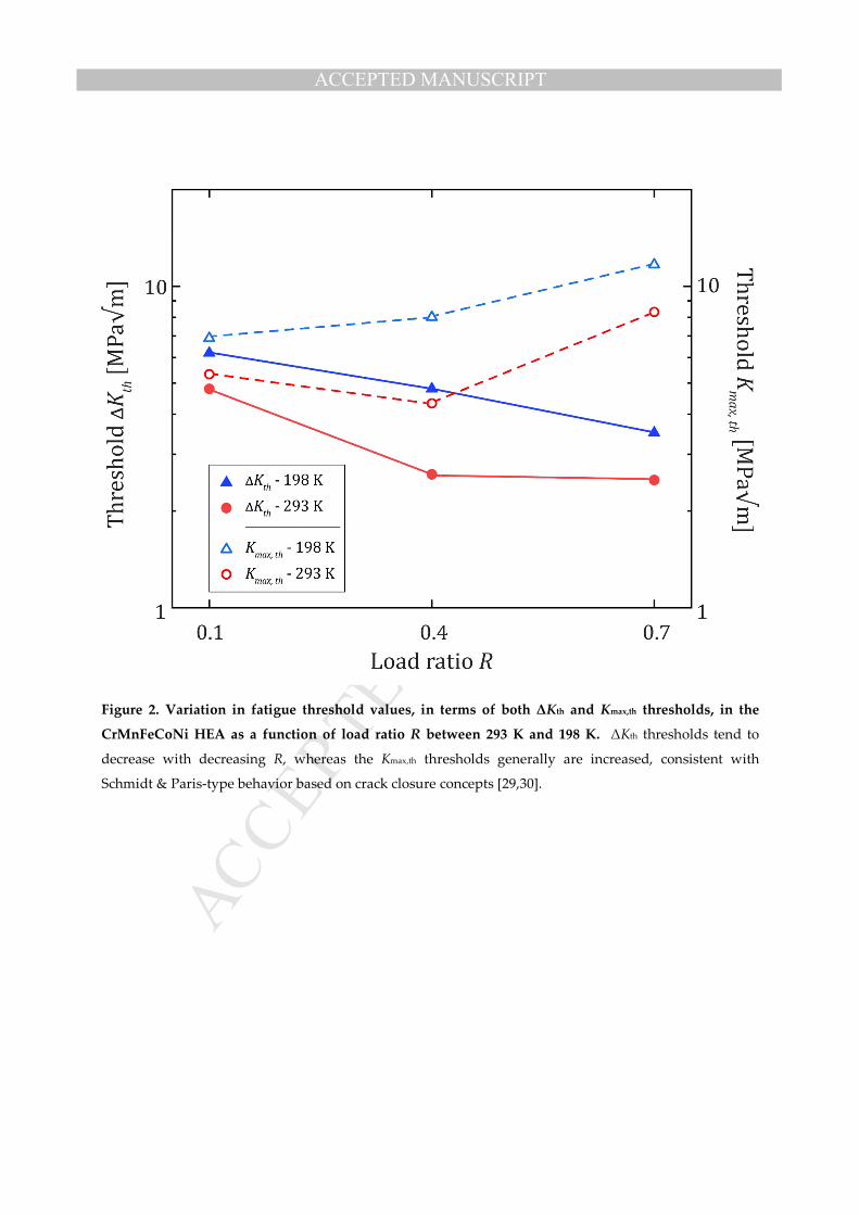
Figure 2. Variation in fatigue threshold values, in terms of both ΔKth and Kmax,th thresholds, in the
CrMnFeCoNi HEA as a function of load ratio R between 293 K and 198 K. ΔKth thresholds tend to
decrease with decreasing R, whereas the Kmax,th thresholds generally are increased, consistent with
Schmidt & Paris-type behavior based on crack closure concepts [29,30].

MANUSCRIP
T
ACCEPTED
ACCEPTED MANUSCRIPT
Figure 3. Overview of fractography for all nine testing conditions at a moderately high ΔK ~ 8 to 17
MPa√m for fatigue-crack growth in the CrMnFeCoNi HEA. A greater degree of facet-like features is
seen at lower temperatures, particularly lower growth rates, with an increasing degree of transgranular
fracture at higher ΔK levels. In general, increases in R and in temperature both correlate with a greater
degree of plastic deformation of the fracture surfaces as characterized by an increasing prominence of
fatigue striations.

MANUSCRIP
T
ACCEPTED
ACCEPTED MANUSCRIPT
Figure 4. Striations and other microfeatures observed in higher R-ratio fatigue-crack growth testing of
the CrMnFeCoNi HEA. Images (a) and (b) are 198 K tested samples at R = 0.4 and 0.7, respectively;
images (c) and (d) are 293 K at R = 0.4 and 0.7, respectively. Striations featured prominently on the
fracture surfaces of samples of all loading states, with particular prominence at higher ΔK levels, as this
corresponds to higher crack-growth rates and thus larger striation spacings. Additionally, striations were
found at lower ΔK levels at ambient temperature, and again appeared to be more prominent at the higher
R-ratios.

MANUSCRIP
T
ACCEPTED
ACCEPTED MANUSCRIPT
Figure 5. Deformation mechanisms in the vicinity of the crack tip in the CrMnFeCoNi high-entropy
alloy (HEA) fatigue tested under R-ratios of 0.1 and 0.7 at 77 K. (a) Low-magnification secondary
electron (SE) images captured in the crack-tip regions on the sliced mid-plane section of the C(T)
specimen. (b) High-magnification back-scattered electron (BSE) images and electron-backscatter
diffraction (EBSD) scans taken from the sample subjected to R = 0.1 with ΔK ≈ 29 MPa√m (Kmax ≈ 32
MPa√m). At higher ∆K levels, fracture is predominately trangranular, but an intergranular faceted mode
of fracture becomes more prominent as the growth rates are reduced. BSE scans reveal the formation of
dislocation cells and deformation nano-twins in the wake of the propagated crack within a region of 1~3
grains. The EBSD image, which is an overlaid map of inverse pole figure (IPF) and image quality (IQ)
clearly shows deformation-induced nano-twinning at 77 K. Nano-twinning is confirmed by line scans
across the twin boundaries, showing the 60° misorientation angle between the twin domain and the
parent grain domain. (c) Corresponding BSE and EBSD images taken from the sample subjected to R = 0.7
with ΔK ≈ 20 MPa√m show pronounced nano-twinning and dislocation cells formed in the wake of the
propagated crack.

MANUSCRIP
T
ACCEPTED
ACCEPTED MANUSCRIPT

MANUSCRIP
T
ACCEPTED
ACCEPTED MANUSCRIPT
This manuscript has been co-authored by UT-Battelle, LLC under Contract No. DE-AC05-00OR22725
with the U.S. Department of Energy. The United States Government retains and the publisher, by
accepting the article for publication, acknowledges that the United States Government retains a non-
exclusive, paid-up, irrevocable, world-wide license to publish or reproduce the published form of this
manuscript, or allow others to do so, for United States Government purposes. The Department of Energy
will provide public access to these results of federally sponsored research in accordance with the DOE
Public Access Plan (http://energy.gov/downloads/doe-public-access-plan).

MANUSCRIP
T
ACCEPTED
ACCEPTED MANUSCRIPT
Highlights
• Fatigue-crack growth rates in the CrMnFeCoNi high-entropy alloy show Paris law exponents of ~2 to 4
• Such mid-range of growth rates are comparable with those of most traditional metallic alloys
• Crack growth resistance is lower at high load ratios especially at low near-threshold growth rates
• Fatigue thresholds in this Cantor alloy are increased with decreasing temperature below ambient
• The higher low-temperature thresholds are primarily due to crack closure from faceted crack paths