TECHNICAL & SERVICE MANUAL PUMY...
126
TECHNICAL & SERVICE MANUAL OUTDOOR UNIT No. OCH612 HFC utilized R410A May 2016 Note: • This service manual describes technical data of the outdoor units only. <Outdoor unit> [Model Name] Model name indication PARTS CATALOG (OCB612) PUMY-P36NKMU1 PUMY-P48NKMU1 PUMY-P36NKMU1-BS PUMY-P48NKMU1-BS Salt proof model PUMY-P36NKMU1 PUMY-P48NKMU1 PUMY-P36NKMU1-BS PUMY-P48NKMU1-BS [Service Ref.] CONTENTS 1. SAFETY PRECAUTION .................................... 2 2. OVERVIEW OF UNITS ...................................... 5 3. SPECIFICATIONS ........................................... 10 4. DATA ................................................................. 11 5. OUTLINES AND DIMENSIONS ...................... 23 6. WIRING DIAGRAM .......................................... 24 7. NECESSARY CONDITIONS FOR SYSTEM CONSTRUCTION ...... 25 8. TROUBLESHOOTING ..................................... 35 9. ELECTRICAL WIRING ................................... 110 10. REFRIGERANT PIPING TASKS .................... 115 11. DISASSEMBLY PROCEDURE ....................... 119 SPLIT-TYPE, HEAT PUMP AIR CONDITIONERS
Transcript of TECHNICAL & SERVICE MANUAL PUMY...
TECHNICAL & SERVICE MANUAL
OUTDOOR UNIT
No. OCH612
HFCutilized
R410A
May 2016
Note:• This service manual describes
technical data of the outdoor units only.
<Outdoor unit>[Model Name]
Model name indication
PARTS CATALOG (OCB612)
PUMY-P36NKMU1
PUMY-P48NKMU1
PUMY-P36NKMU1-BS
PUMY-P48NKMU1-BS
Salt proof model
PUMY-P36NKMU1PUMY-P48NKMU1
PUMY-P36NKMU1-BSPUMY-P48NKMU1-BS
[Service Ref.]
CONTENTS 1. SAFETY PRECAUTION .................................... 2 2. OVERVIEW OF UNITS ...................................... 5 3. SPECIFICATIONS ........................................... 10 4. DATA .................................................................11 5. OUTLINES AND DIMENSIONS ...................... 23 6. WIRING DIAGRAM .......................................... 24 7. NECESSARY CONDITIONS FOR SYSTEM CONSTRUCTION ...... 25 8. TROUBLESHOOTING ..................................... 35 9. ELECTRICAL WIRING ...................................11010. REFRIGERANT PIPING TASKS ....................11511. DISASSEMBLY PROCEDURE .......................119
SPLIT-TYPE, HEAT PUMP AIR CONDITIONERS
2
Cautions for units utilizing refrigerant R410A1-1. CAUTIONS RELATED TO NEW REFRIGERANT
Use new refrigerant pipes.
Store the piping indoors, and both ends of the piping sealed until just before brazing. (Leave elbow joints, etc. in their packaging.)
Avoid using thin pipes.
Charge refrigerant from liquid phase of gascylinder.If the refrigerant is charged from gas phase, composition change may occur in refrigerant and the efficiency will be lowered.
Do not use refrigerant other than R410A.
If other refrigerant (R22, etc.) is used, chlorine in refrige-rant can cause deterioration of refrigerant oil, etc.
Use a vacuum pump with a reverse flow check valve.Vacuum pump oil may flow back into refrigerant cycle and that can cause deterioration of refrigerant oil, etc.
Use the following tools specifically designed for use with R410A refrigerant.The following tools are necessary to use R410A refrigerant.
Handle tools with care.
If dirt, dust or moisture enters into refrigerant cycle, that cancause deterioration of refrigerant oil or malfunction of com-pressor.
Do not use a charging cylinder.
If a charging cylinder is used, the composition of refrigera-nt will change and the efficiency will be lowered.
Flare tool
Electronic refrigerant charging scale
Vacuum pump adaptorSize adjustment gauge
Gauge manifold
Torque wrenchGas leak detectorCharge hose
Tools for R410A
Contamination inside refrigerant piping can cause deterio-ration of refrigerant oil, etc.
If dirt, dust or moisture enters into refrigerant cycle, that can cause deterioration of refrigerant oil or malfunction of com-pressor.
If large amount of mineral oil enters, that can cause deterio-ration of refrigerant oil, etc.
Make sure that the inside and outside of refrige-rant piping is clean and it has no contaminantssuch as sulfur, oxides, dirt, shaving particles, etc,which are hazard to refrigerant cycle.In addition, use pipes with specified thickness.
The refrigerant oil applied to flare and flangeconnections must be ester oil, ether oil or alkylbenzene oil in a small amount.
Ventilate the room if refrigerant leaks during operation. If refrigerant comes into contact witha flame, poisonous gases will be released.
Use the specified refrigerant only.
Never use any refrigerant other than that specified.Doing so may cause a burst, an explosion, or fire when the unit is being used, serviced, or disposed of.Correct refrigerant is specified in the manuals and on the spec labels provided with our products.We will not be held responsible for mechanical failure, system malfunction, unit breakdown or accidents caused by failure to follow the instructions.
1 SAFETY PRECAUTION
OCH612
3
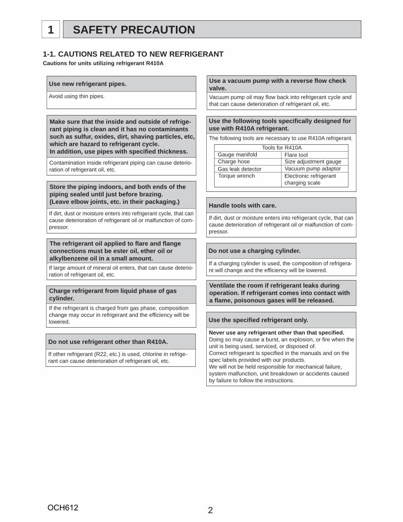
Electronic weighing scale
Unit
[3] Service tools Use the below service tools as exclusive tools for R410A refrigerant.
[1] Cautions for service (1) Perform service after recovering the refrigerant left in unit completely. (2) Do not release refrigerant in the air. (3) After completing service, charge the cycle with specified amount of refrigerant. (4) If moisture or foreign matter might have entered the refrigerant piping during service, ensure to remove them.
[2] Additional refrigerant charge When charging directly from cylinder (1) Check that cylinder for R410A on the market is a syphon type. (2) Charging should be performed with the cylinder of syphon stood vertically. (Refrigerant is charged from liquid phase.)
Although "-BS" model has been designed to be resistant to salt damage, observe the following precautions to maintain the performance of the unit.(1) Avoid installing the unit in a location where it will be exposed directly to seawater or sea breeze.(2) If the cover panel may become covered with salt, be sure to install the unit in a location where the salt will be washed away by rainwater. (If a sunshade is installed, rainwater may not clean the panel.)(3) To ensure that water does not collect in the base of the outdoor unit, make sure that the base is level, not at angle. Water collecting in the base of the outdoor unit could cause rust.(4) If the unit is installed in a coastal area, clean the unit with water regularly to remove any salt build-up.(5) If the unit is damaged during installation or maintenance, be sure to repair it.(6) Be sure to check the condition of the unit regularly.(7) Be sure to install the unit in a location with good drainage.
1-2. PRECAUTIONS FOR SALT PROOF TYPE "-BS" MODEL
No. Tool name Specifications1 Gauge manifold · Only for R410A
· Use the existing fitting specifications. (UNF1/2)· Use high-tension side pressure of 768.7 PSI [5.3 MPa.G] or over.
2 Charge hose · Only for R410A· Use pressure performance of 738.2 PSI [5.09MPa.G] or over.
3 Electronic scale —
4 Gas leak detector · Use the detector for R134a, R407C or R410A.5 Adaptor for reverse flow check · Attach on vacuum pump.6 Refrigerant charge base —
7 Refrigerant cylinder · Only for R410A · Top of cylinder (Pink)· Cylinder with syphon
8 Refrigerant recovery equipment —
OCH612
4
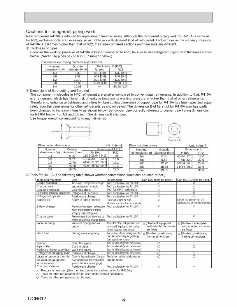
Cautions for refrigerant piping workNew refrigerant R410A is adopted for replacement inverter series. Although the refrigerant piping work for R410A is same as for R22, exclusive tools are necessary so as not to mix with different kind of refrigerant. Furthermore as the working pressure of R410A is 1.6 times higher than that of R22, their sizes of flared sections and flare nuts are different.1 Thickness of pipes
Because the working pressure of R410A is higher compared to R22, be sure to use refrigerant piping with thickness shown below. (Never use pipes of 7/256 in [0.7 mm] or below.)
2 Dimensions of flare cutting and flare nutThe component molecules in HFC refrigerant are smaller compared to conventional refrigerants. In addition to that, R410A is a refrigerant, which has higher risk of leakage because its working pressure is higher than that of other refrigerants. Therefore, to enhance airtightness and intensity, flare cutting dimension of copper pipe for R410A has been specified sepa-rately from the dimensions for other refrigerants as shown below. The dimension B of flare nut for R410A also has partly been changed to increase intensity as shown below. Set copper pipe correctly referring to copper pipe flaring dimensions for R410A below. For 1/2 and 5/8 inch, the dimension B changes. Use torque wrench corresponding to each dimension.
3 Tools for R410A (The following table shows whether conventional tools can be used or not.)
1/43/81/25/83/4
6.359.5212.7015.8819.05
1/32 [0.8] 1/32 [0.8] 1/32 [0.8] 5/128 [1.0]
—
1/32 [0.8] 1/32 [0.8] 1/32 [0.8]5/128 [1.0]5/128 [1.0]
Nominaldimensions (in)
Diagram below: Piping diameter and thicknessOutside
diameter (mm)Thickness : in [mm]
R410A R22
1/43/81/25/83/4
6.359.5212.7015.8819.05
11/32-23/64 [ 9.1]1/2-33/64 [13.2]41/64-21/32 [16.6]49/64-25/32 [19.7] —
9.013.016.219.423.3
Nominaldimensions (in)
Flare cutting dimensionsOutside
diameter (mm)Dimension A ( )+0
-0.4
Unit : in [mm]
R410A R221/43/81/25/83/4
6.359.5212.7015.8819.05
43/64 [17.0] 7/8 [22.0] 1-3/64 [26.0] 1-9/64 [29.0]
17.022.024.027.036.0
Nominaldimensions (in)
Flare nut dimensionsOutside
diameter (mm)Dimension B
Unit: in [mm]
R410A R22
—
Gauge manifoldCharge hoseGas leak detectorRefrigerant recovery equipmentRefrigerant cylinderApplied oil
Safety charger
Charge valve
Vacuum pump
Flare tool
BenderPipe cutterWelder and nitrogen gas cylinderRefrigerant charging scaleVacuum gauge or thermis-tor vacuum gauge and vacuum valveCharging cylinder
Air purge, refrigerant chargeand operation checkGas leak checkRefrigerant recoveryRefrigerant chargeApply to flared section
Prevent compressor malfunction when charging refrigerant by spraying liquid refrigerantPrevent gas from blowing out when detaching charge hoseVacuum drying and airpurge
Flaring work of piping
Bend the pipesCut the pipesWeld the pipesRefrigerant chargeCheck the degree of vacuum. (Vacuum valve prevents back flow of oil and refri-gerant to thermistor vacuum gauge)Refrigerant charge
Tool exclusive for R410ATool exclusive for R410ATool for HFC refrigerantTool exclusive for R410ATool exclusive for R410AEster oil, ether oil andalkylbenzene oil (minimum amount)Tool exclusive for R410A
Tool exclusive for R410A
Tools for other refrigerants can be used if equipped with adop-ter for reverse flow checkTools for other refrigerants can be used by adjusting flaring dimensionTools for other refrigerants can be usedTools for other refrigerants can be usedTools for other refrigerants can be usedTools for other refrigerants can be usedTools for other refrigerants can be used
Tool exclusive for R410A
Tools and materials Use R410A tools Can R22 tools be used?
(Usable if equipped with adopter for rever- se flow) (Usable by adjusting flaring dimension)
Can R407C tools be used?
Ester oil, ether oil: Alkylbenzene oil: minimum amount
(Usable if equipped with adopter for rever- se flow) (Usable by adjusting flaring dimension)
: Prepare a new tool. (Use the new tool as the tool exclusive for R410A.) : Tools for other refrigerants can be used under certain conditions.: Tools for other refrigerants can be used.
Dimension A
Dimension B
OCH612
5
2 OVERVIEW OF UNITS
2-1. Auxiliary HEATING ON/OFF CONTROL SET-UP
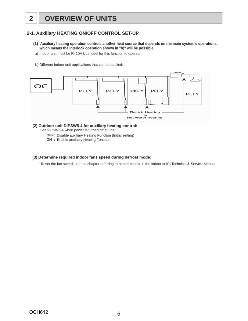
(1) Auxiliary heating operation controls another heat source that depends on the main system's operations,which means the interlock operation shown in "b)" will be possible.
a)
b) Different Indoor unit applications that can be applied:
(2) Outdoor unit DIPSW5-4 for auxiliary heating control:Set DIPSW5-4 when power is turned off at unit.
OFF: Disable auxiliary Heating Function (Initial setting)ON : Enable auxiliary Heating Function
Indoor unit must be R410A UL model for this function to operate.
(3) Determine required indoor fans speed during defrost mode:To set the fan speed, see the chapter referring to heater control in the indoor unit’s Technical & Service Manual.
OCH612

6
When the set temperature ranges overlap, the previously set pattern (1,2 or 3) has a priority.The stage 1 has the highest priority, 2 the second and then 3.
b) Based on above chart listed the sequence of operation on "On ambient decrease" Stage 1 :(TH7 = > 10:) : the outdoor unit runs in HP mode. Stage 2 :(TH7 = 10: to -25:) : the outdoor unit runs in HP mode with auxiliary heating. Stage 3 :(TH7 = < -25:) : Auxiliary heating only (Outdoor unit is OFF).
c) Based on above chart listed the sequence of operation on "On ambient increase" Stage 3 :(TH7 = < 0:) : Auxiliary heating only (Outdoor unit is OFF). Stage 2 :(TH7 = > 0: to 20:) : Auxiliary heating with outdoor unit in HP mode. Stage 1 :(TH7 = > 20:) : Outdoor unit in HP mode only.
(4) Determine fan airflow setting during indoor thermo-OFF conditions:a) These settings are done within Indoor DIPSW1-7 and DIPSW1-8, see chart below for options.b) Recommended SW1-7 OFF and SW1-8 ON will determine airflow based on "Setting on the remote controller".
Fan speed setting
Fan speed setting
OFF ON
SW1-7 SW1-8OFF OFF Very low
ON OFF Low
OFF ONSetting on
remote controller
ON ON Stopped
Auxiliary heating signal
Thermo condition
(5) Setting outdoor unit and auxiliary heat switch over temperatures.When the DIPSW 5-4 is set to "ON", the outdoor unit and the contact output operates as shown below.
a) Outdoor default setting and operations are shown below:
Stage 1Amb. decreasing - Outdoor unit HP operationAmb. increasing - Defrost : Heater contact ON signal
- Other than defrost : Contact OFF
Stage 2- Outdoor unit HP operation- Heater contact ON signal
Stage 3 - Outdoor unit OFF (Standby)- Heater contact ON signal
TH7 = Outdoor temperature a-25-C[-13-F]
b0-C
[32-F]
c10-C[50-F]
d20-C[68-F]
Setting on remote
controller
OCH612
7
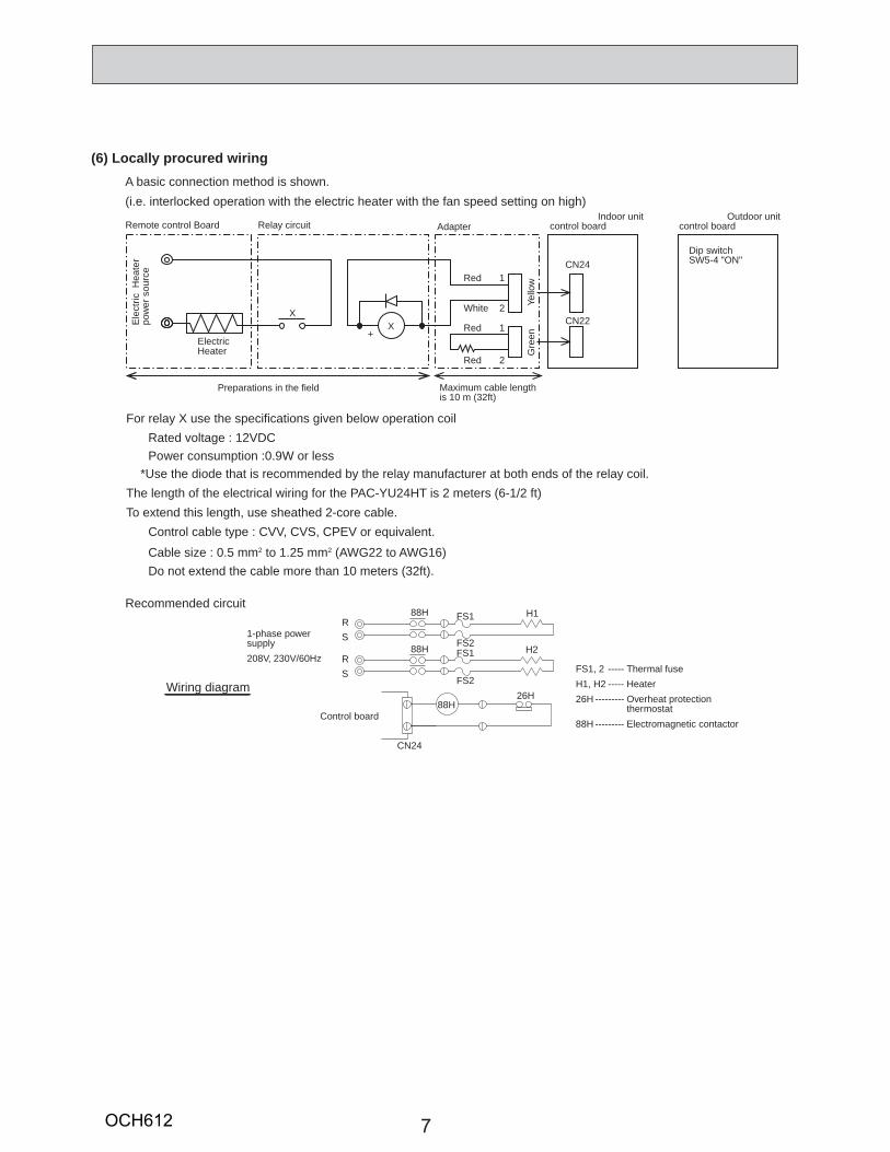
(6) Locally procured wiringA basic connection method is shown.(i.e. interlocked operation with the electric heater with the fan speed setting on high)
Recommended circuit
CN24
CN22X+
X
Remote control Board Relay circuit AdapterIndoor unit
control boardOutdoor unit
control board
Ele
ctric
Hea
ter
pow
er s
ourc
e
ElectricHeater
Red 1
White 2
Dip switchSW5-4 "ON"
Preparations in the field Maximum cable lengthis 10 m (32ft)
Red 1
Red 2
Yello
wG
reen
FS1
FS2FS1
FS2
RS
RS
CN24
H288H
H188H
26H88H
1-phase powersupply208V, 230V/60Hz
Control board
FS1, 2 ----- Thermal fuseH1, H2 ----- Heater26H --------- Overheat protection
thermostat88H --------- Electromagnetic contactor
Wiring diagram
For relay X use the specifications given below operation coilRated voltage : 12VDCPower consumption : 0.9W or less
*Use the diode that is recommended by the relay manufacturer at both ends of the relay coil.The length of the electrical wiring for the PAC-YU24HT is 2 meters (6-1/2 ft)To extend this length, use sheathed 2-core cable.
Control cable type : CVV, CVS, CPEV or equivalent.Cable size : 0.5 mm2 to 1.25 mm2 (AWG22 to AWG16)Do not extend the cable more than 10 meters (32ft).
OCH612
8
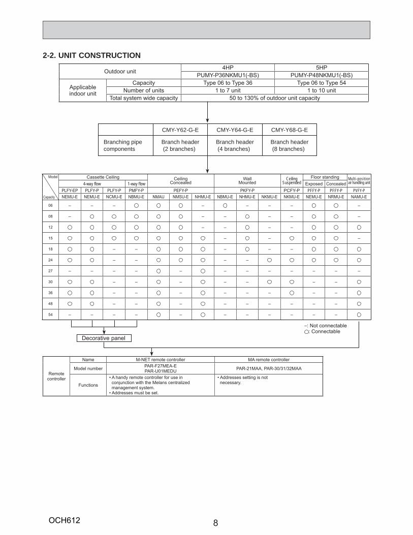
2-2. UNIT CONSTRUCTION
Branching pipecomponents
Branch header (2 branches)
Branch header (4 branches)
Branch header (8 branches)
CMY-Y62-G-E CMY-Y64-G-E CMY-Y68-G-E
Decorative panel
Model
Capacity
Cassette Ceiling Ceiling Concealed
Wall Mounted
CeilingSuspended
Floor standing Multi-posit ion air handling unit4-way fl ow 1-way fl ow Exposed Concealed
PLFY-EP PLFY-P PLFY-P PMFY-P PEFY-P PKFY-P PCFY-P PFFY-P PFFY-P PVFY-PNEMU-E NEMU-E NCMU-E NBMU-E NMAU NMSU-E NHMU-E NBMU-E NHMU-E NKMU-E NKMU-E NEMU-E NRMU-E NAMU-E
06 – – – – – – – –
08 – – – – – –
12 – – – –
15 – – –
18 – – – – –
24 – – – –
27 – – – – – – – – – – – –
30 – – – – – – –
36 – – – – – – – –
48 – – – – – – – – –
54 – – – – – – – – – – –
Outdoor unit 4HP 5HPPUMY-P36NKMU1(-BS) PUMY-P48NKMU1(-BS)
Applicableindoor unit
Capacity Type 06 to Type 36 Type 06 to Type 54Number of units 1 to 7 unit 1 to 10 unit
Total system wide capacity 50 to 130% of outdoor unit capacity
Remotecontroller
Name M-NET remote controller MA remote controller
Model number PAR-F27MEA-EPAR-U01MEDU PAR-21MAA, PAR-30/31/32MAA
Functions
• A handy remote controller for use in conjunction with the Melans centralized management system.• Addresses must be set.
• Addresses setting is not necessary.
–: Not connectable: Connectable
OCH612
9
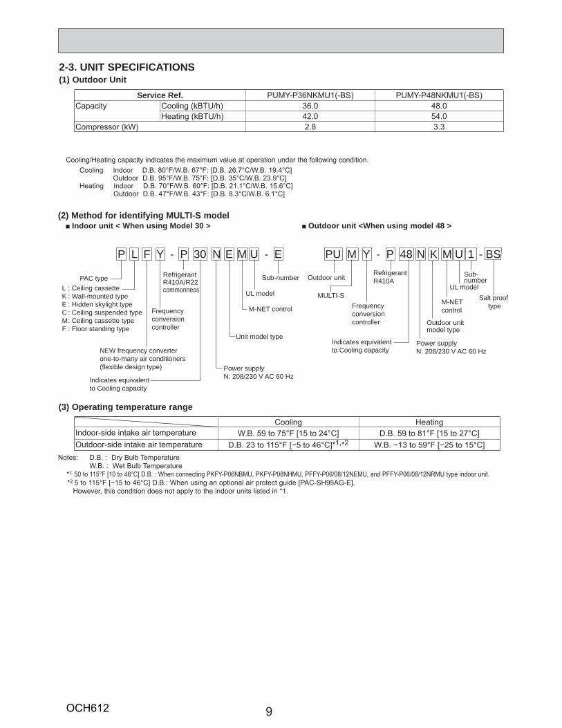
2-3. UNIT SPECIFICATIONS
(2) Method for identifying MULTI-S model
(1) Outdoor Unit
Indoor unit < When using Model 30 > Outdoor unit <When using model 48 >
P L F Y - P 30 N E M U - E PU M Y - P 48 N K M U 1 - BS
PAC type
Frequencyconversioncontroller
RefrigerantR410A/R22commonness
RefrigerantR410A
NEW frequency converterone-to-many air conditioners(flexible design type)
Indicates equivalentto Cooling capacity
Indicates equivalentto Cooling capacity
Power supplyN: 208/230 V AC 60 Hz
Power supplyN: 208/230 V AC 60 Hz
L : Ceiling cassetteK : Wall-mounted typeE : Hidden skylight typeC : Ceiling suspended typeM : Ceiling cassette typeF : Floor standing type
Outdoor unitmodel type
Sub-number Sub-number
Unit model type
M-NET control
UL modelM-NET controlFrequency
conversioncontroller
Outdoor unit
MULTI-S Salt proof type
UL model
Cooling/Heating capacity indicates the maximum value at operation under the following condition. Cooling Indoor D.B. 80°F/W.B. 67°F: [D.B. 26.7°C/W.B. 19.4°C]
Outdoor D.B. 95°F/W.B. 75°F: [D.B. 35°C/W.B. 23.9°C]Heating Indoor D.B. 70°F/W.B. 60°F: [D.B. 21.1°C/W.B. 15.6°C]
Outdoor D.B. 47°F/W.B. 43°F: [D.B. 8.3°C/W.B. 6.1°C]
(3) Operating temperature range
Notes: D.B. : Dry Bulb Temperature W.B. : Wet Bulb Temperature *1 50 to 115°F [10 to 46°C] D.B. : When connecting PKFY-P06NBMU, PKFY-P08NHMU, PFFY-P06/08/12NEMU, and PFFY-P06/08/12NRMU type indoor unit. *2 5 to 115°F [−15 to 46°C] D.B.: When using an optional air protect guide [PAC-SH95AG-E]. However, this condition does not apply to the indoor units listed in *1.
Service Ref. PUMY-P36NKMU1(-BS) PUMY-P48NKMU1(-BS)Capacity Cooling (kBTU/h) 36.0 48.0
Heating (kBTU/h) 42.0 54.0Compressor (kW) 2.8 3.3
Cooling HeatingIndoor-side intake air temperature W.B. 59 to 75°F [15 to 24°C] D.B. 59 to 81°F [15 to 27°C]Outdoor-side intake air temperature D.B. 23 to 115°F [−5 to 46°C]*1,*2 W.B. −13 to 59°F [−25 to 15°C]
OCH612
10
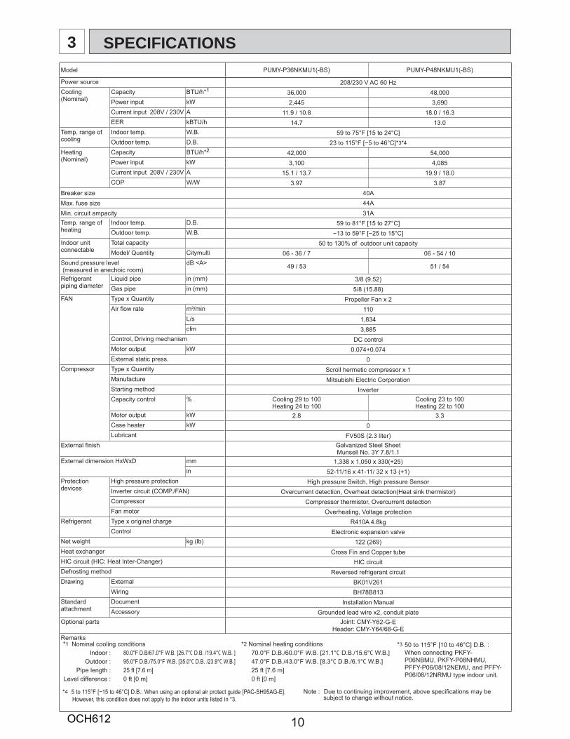
3 SPECIFICATIONSModel PUMY-P36NKMU1(-BS) PUMY-P48NKMU1(-BS)
Power source 208/230 V AC 60 HzCooling(Nominal)
Capacity BTU/h*1 36,000 48,000Power input kW 2,445 3,690Current input 208V / 230V A 11.9 / 10.8 18.0 / 16.3EER kBTU/h 14.7 13.0
Temp. range ofcooling
Indoor temp. W.B. 59 to 75°F [15 to 24°C] Outdoor temp. D.B. 23 to 115°F [−5 to 46°C]*3*4
Heating(Nominal)
Capacity BTU/h*2 42,000 54,000Power input kW 3,100 4,085Current input 208V / 230V A 15.1 / 13.7 19.9 / 18.0COP W/W 3.97 3.87
Breaker size 40AMax. fuse size 44AMin. circuit ampacity 31ATemp. range ofheating
Indoor temp. D.B. 59 to 81°F [15 to 27°C]Outdoor temp. W.B. −13 to 59°F [−25 to 15°C]
Indoor unitconnectable
Total capacity 50 to 130% of outdoor unit capacityModel/ Quantity Citymulti 06 - 36 / 7 06 - 54 / 10
Sound pressure level (measured in anechoic room)
dB <A> 49 / 53 51 / 54
Refrigerantpiping diameter
Liquid pipe in (mm) 3/8 (9.52)Gas pipe in (mm) 5/8 (15.88)
FAN Type x Quantity Propeller Fan x 2Air fl ow rate m³/min 110
L/s 1,834cfm 3,885
Control, Driving mechanism DC controlMotor output kW 0.074+0.074External static press. 0
Compressor Type x Quantity Scroll hermetic compressor x 1Manufacture Mitsubishi Electric CorporationStarting method InverterCapacity control % Cooling 29 to 100
Heating 24 to 100Cooling 23 to 100Heating 22 to 100
Motor output kW 2.8 3.3Case heater kW 0Lubricant FV50S (2.3 liter)
External fi nish Galvanized Steel SheetMunsell No. 3Y 7.8/1.1
External dimension HxWxD mm 1,338 x 1,050 x 330(+25)in 52-11/16 x 41-11/ 32 x 13 (+1)
Protection devices
High pressure protection High pressure Switch, High pressure SensorInverter circuit (COMP./FAN) Overcurrent detection, Overheat detection(Heat sink thermistor)Compressor Compressor thermistor, Overcurrent detectionFan motor Overheating, Voltage protection
Refrigerant Type x original charge R410A 4.8kgControl Electronic expansion valve
Net weight kg (lb) 122 (269)Heat exchanger Cross Fin and Copper tubeHIC circuit (HIC: Heat Inter-Changer) HIC circuitDefrosting method Reversed refrigerant circuitDrawing External BK01V261
Wiring BH78B813Standard attachment
Document Installation ManualAccessory Grounded lead wire x2, conduit plate
Optional parts Joint: CMY-Y62-G-EHeader: CMY-Y64/68-G-E
Remarks*1 Nominal cooling conditions *2 Nominal heating conditions *3 50 to 115°F [10 to 46°C] D.B. :
When connecting PKFY-P06NBMU, PKFY-P08NHMU, PFFY-P06/08/12NEMU, and PFFY-P06/08/12NRMU type indoor unit.
Indoor : 80.0°F D.B/67.0°F W.B. [26.7°C D.B. /19.4°C W.B. ] 70.0°F D.B./60.0°F W.B. [21.1°C D.B./15.6°C W.B.]Outdoor : 95.0°F D.B./75.0°F W.B. [35.0°C D.B. /23.9°C W.B.] 47.0°F D.B./43.0°F W.B. [8.3°C D.B./6.1°C W.B.]
Pipe length : 25 ft [7.6 m] 25 ft [7.6 m]Level difference : 0 ft [0 m] 0 ft [0 m]
Note : Due to continuing improvement, above specifi cations may be subject to change without notice.
*4 5 to 115°F [−15 to 46°C] D.B.: When using an optional air protect guide [PAC-SH95AG-E]. However, this condition does not apply to the indoor units listed in *3.
OCH612
11
4
Capacity of indoor unit
Model 08Model Number for indoor unit
Model Capacity 8.0
Model 06
6.0
Model 12
12.0
Model 15
15.0
Model 18
18.0
Model 24
24.0
Model 27
27.0
Model 30
30.0
Model 36
36.0
Model 48
48.0
Model 54
54.0
DATA
0 50 100 150 200 250 300 350 400 450 500 550 6000.50
0.55
0.60
0.65
0.70
0.75
0.80
0.85
0.90
0.95
1.00
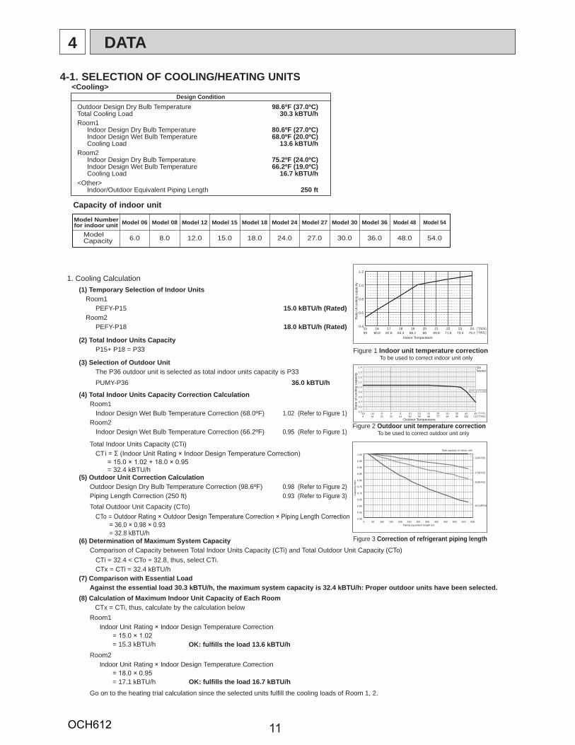
<Cooling>Design Condition
Outdoor Design Dry Bulb Temperature 98.6ºF (37.0ºC)Total Cooling Load 30.3 kBTU/hRoom1
Indoor Design Dry Bulb Temperature 80.6ºF (27.0ºC)Indoor Design Wet Bulb Temperature 68.0ºF (20.0ºC)Cooling Load 13.6 kBTU/h
Room2Indoor Design Dry Bulb Temperature 75.2ºF (24.0ºC)Indoor Design Wet Bulb Temperature 66.2ºF (19.0ºC)Cooling Load 16.7 kBTU/h
<Other>Indoor/Outdoor Equivalent Piping Length 250 ft
1. Cooling Calculation(1) Temporary Selection of Indoor Units
Room1PEFY-P15 15.0 kBTU/h (Rated)
Room2PEFY-P18 18.0 kBTU/h (Rated)
(2) Total Indoor Units CapacityP15+ P18 = P33
(3) Selection of Outdoor UnitThe P36 outdoor unit is selected as total indoor units capacity is P33PUMY-P36 36.0 kBTU/h
(4) Total Indoor Units Capacity Correction CalculationRoom1
Indoor Design Wet Bulb Temperature Correction (68.0ºF) 1.02 (Refer to Figure 1)
Figure 1 Indoor unit temperature correction To be used to correct indoor unit only
Figure 2 Outdoor unit temperature correction To be used to correct outdoor unit only
Figure 3 Correction of refrigerant piping length
Room2Indoor Design Wet Bulb Temperature Correction (66.2ºF) 0.95 (Refer to Figure 1)
CT
= 32.4 kBTU/h(5) Outdoor Unit Correction Calculation
Outdoor Design Dry Bulb Temperature Correction (98.6ºF) 0.98 (Refer to Figure 2)Piping Length Correction (250 ft) 0.93 (Refer to Figure 3)Total Outdoor Unit Capacity (CTo)
Total Indoor Units Capacity (CTi)
CTo =
= 32.8 kBTU/h(6) Determination of Maximum System Capacity
Comparison of Capacity between Total Indoor Units Capacity (CTi) and Total Outdoor Unit Capacity (CTo)CTi = 32.4 < CTo = 32.8, thus, select CTi. CTx = CTi = 32.4 kBTU/h
(7) Comparison with Essential LoadAgainst the essential load 30.3 kBTU/h, the maximum system capacity is 32.4 kBTU/h: Proper outdoor units have been selected.
(8) Calculation of Maximum Indoor Unit Capacity of Each RoomCTx = CTi, thus, calculate by the calculation below
Room1Indoor Unit Rating Indoor Design Temperature Correction
= 15.3 kBTU/h OK: fulfills the load 13.6 kBTU/hRoom2
Indoor Unit Rating Indoor Design Temperature Correction
= 17.1 kBTU/h OK: fulfills the load 16.7 kBTU/hGo on to the heating trial calculation since the selected units fulfill the cooling loads of Room 1, 2.
IndoorTemperature
15 16 17 18 19 20 21 22 23 2459 60.8 62.6 64.4 66.2 68 69.8 71.6 73.4 75.2
0.4
0.6
0.8
1.0
1.2
Rat
io o
f coo
ling
capa
city
Indoor Temperature
[°CW.B.] [°FW.B.]
-15 -10 -5 0 5 10 15 20 25 30 35 40 455 14 23 32 41 50 59 68 77 86 95 104 113
0.5
0.6
0.7
0.8
0.9
1.0
1.1
1.2
1.3
1.4
Rat
io o
f coo
ling
capa
city
Outdoor Temperature
[°C D.B.] [°F W.B.]
19.4°C (67.0°F) W.B
18 [kBTU/h]
27 [kBTU/h]
36 [kBTU/h]
Cap
acity
ratio
Piping equivalent length (m)
Total capacity of indoor unit
46.8 [kBTU/h]
4-1. SELECTION OF COOLING/HEATING UNITS
OCH612
12
Capacity of indoor unit
Model 08Model Number for indoor unit
Model Capacity 9.0
Model 06
6.7
Model 12
13.5
Model 15
17.0
Model 18
20.0
Model 24
27.0
Model 27
30.0
Model 30
34.0
Model 36
40.0
Model 48
54.0
Model 54
60.0
0 50 100 150 200 250 300 350 400 450 500 550 6000.70
0.75
0.80
0.85
0.90
0.95
1.00
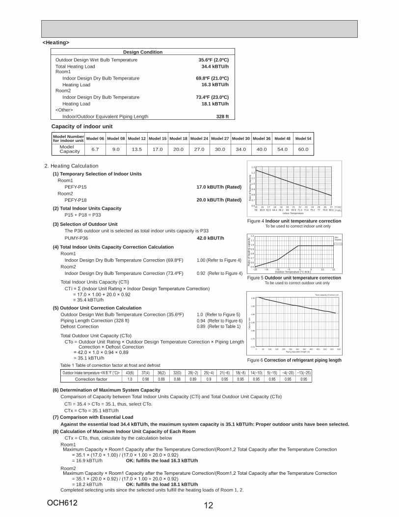
<Heating>
Design ConditionOutdoor Design Wet Bulb Temperature 35.6ºF (2.0ºC)Total Heating Load 34.4 kBTU/hRoom1
Indoor Design Dry Bulb Temperature 69.8ºF (21.0ºC)Heating Load 16.3 kBTU/h
Room2Indoor Design Dry Bulb Temperature 73.4ºF (23.0ºC)Heating Load 18.1 kBTU/h
<Other>Indoor/Outdoor Equivalent Piping Length 328 ft
2. Heating Calculation(1) Temporary Selection of Indoor Units
Room1PEFY-P15 17.0 kBUT/h (Rated)
20.0 kBUT/h (Rated)Room2
PEFY-P18
(2) Total Indoor Units CapacityP15 + P18 = P33
(3) Selection of Outdoor UnitThe P36 outdoor unit is selected as total indoor units capacity is P33PUMY-P36 42.0 kBUT/h
(4) Total Indoor Units Capacity Correction CalculationRoom1
Indoor Design Dry Bulb Temperature Correction (69.8ºF) 1.00 (Refer to Figure 4)Room2
Indoor Design Dry Bulb Temperature Correction (73.4ºF) 0.92 (Refer to Figure 4)
CT
= 35.4 kBTU/h
(5) Outdoor Unit Correction CalculationOutdoor Design Wet Bulb Temperature Correction (35.6ºF) 1.0 (Refer to Figure 5)Piping Length Correction (328 ft)Defrost Correction
0.94 (Refer to Figure 6)0.89 (Refer to Table 1)
Total Outdoor Unit Capacity (CTo)
Total Indoor Units Capacity (CTi)
CTo = Outdoor Unit Rating Outdoor Design Temperature Correction Piping Length Correction Defrost Correction
= 35.1 kBTU/h
(6) Determination of Maximum System CapacityComparison of Capacity between Total Indoor Units Capacity (CTi) and Total Outdoor Unit Capacity (CTo)
CTi = 35.4 > CTo = 35.1, thus, select CTo. CTx = CTo = 35.1 kBTU/h
(7) Comparison with Essential LoadAgainst the essential load 34.4 kBTU/h, the maximum system capacity is 35.1 kBTU/h: Proper outdoor units have been selected.
(8) Calculation of Maximum Indoor Unit Capacity of Each RoomCTx = CTo, thus, calculate by the calculation below
Room1
+= 16.9 kBTU/h OK: fulfills the load 16.3 kBTU/h
Room2
= += 18.2 kBTU/h OK: fulfills the load 18.1 kBTU/h
Completed selecting units since the selected units fulfill the heating loads of Room 1, 2.
Figure 4 Indoor unit temperature correction To be used to correct indoor unit only
Figure 5 Outdoor unit temperature correction To be used to correct outdoor unit only
Figure 6 Correction of refrigerant piping length
0 5 10 150.5
0.6
0.7
0.8
0.9
1.0
1.1
1.2
Rat
io o
f hea
ting
capa
city
Outdoor Temperature [°C W.B.]
21.1°C (70.0°F) D.B
15 16 17 18 19 20 21 22 23 24 25 26 2759 60.8 62.6 64.4 66.2 68 69.8 71.6 73.4 75.2 77 78.8 80.6
0.6
0.7
0.8
0.9
1.0
1.1
1.2
1.3
Rat
io o
f hea
ting
capa
city
Indoor Temperature
[°C D.B.] [°F W.B.]
IndoorTemperature
Cap
acity
ratio
Piping equivalent length (m)
Total capacity of indoor unit
Table 1 Table of correction factor at frost and defrost
Outdoor Intake temperature <W.B.°F (°C)> 43(6) 37(4) 36(2) 32(0) 28(−2) 25(−4) 21(−6) 18(−8) 14(−10) 5(−15) −4(−20) −13(−25)Correction factor 1.0 0.98 0.89 0.88 0.89 0.9 0.95 0.95 0.95 0.95 0.95 0.95
OCH612

13
4-2. CORRECTING BY TEMPERATURE
15 16 17 18 19 20 21 22 23 2459 60.8 62.6 64.4 66.2 68 69.8 71.6 73.4 75.2
0.4
0.6
0.8
1.0
1.2
Rat
io o
f coo
ling
capa
city
Indoor Temperature
[°CW.B.] [°FW.B.]
-15 -10 -5 0 5 10 15 20 25 30 35 40 455 14 23 32 41 50 59 68 77 86 95 104 113
0.5
0.6
0.7
0.8
0.9
1.0
1.1
1.2
1.3
1.4
Rat
io o
f coo
ling
capa
city
Outdoor Temperature
19.4°C (67.0°F) W.B.
[°C W.B.] [°F W.B.]
-15 -10 -5 0 5 10 15 20 25 30 35 40 455 14 23 32 41 50 59 68 77 86 95 104 113
0.0
0.2
0.4
0.6
0.8
1.0
1.2
Rat
io o
f pow
er in
put
Outdoor Temperature
[°C W.B.] [°F W.B.]
20.0°C (68.0°F) W.B.20.0°C (68.0°F) W.B. 24.0°C (75.2°F) W.B.24.0°C (75.2°F) W.B. 22.0°C (71.6°F) W.B.22.0°C (71.6°F) W.B.
19.4°C (67.0°F) W.B.19.4°C (67.0°F) W.B.18.0°C (64.4°F) W.B.18.0°C (64.4°F) W.B.
16.0°C (60.8°F) W.B.16.0°C (60.8°F) W.B.
CITY MULTI could have varied capacity at different designing temperature. Using the nominal cooling/heating capacity value and the ratio below, the capacity can be observed at various temperature.
PUMYP36 P48
Nominal cooling capacity BTU/h 36,000 48,000Input kW 2.445 3.69
Figure 7 Indoor unit temperature correctionTo be used to correct indoor unit capacity only
Figure 8 Outdoor unit temperature correctionTo be used to correct outdoor unit capacity only
<Cooling>
Indoor Temperature
Indoor Temperature
OCH612
14
<Heating>
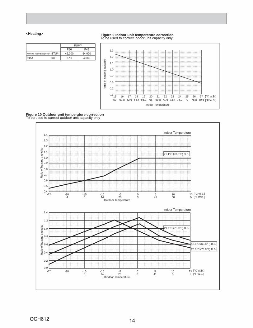
15 16 17 18 19 20 21 22 23 24 25 26 2759 60.8 62.6 64.4 66.2 68 69.8 71.6 73.4 75.2 77 78.8 80.6
0.6
0.7
0.8
0.9
1.0
1.1
1.2
1.3
Rat
io o
f hea
ting
capa
city
Indoor Temperature
[°C W.B.] [°F W.B.]
-25 -20 -15 -10 -5 0 5 10 15-4 5 14 23 3 41 50 5
0.4
0.5
0.6
0.7
0.8
0.9
1.0
1.1
1.2
1.3
1.4
Rat
io o
f hea
ting
capa
city
Outdoor Temperature
[°C W.B.][°F W.B.]
21.1°C (70.0°F) D.B.
-25 -20 -15 -10 -5 0 5 10 155 14 23 3 41 5 5
0.0
0.2
0.4
1.0
0.6
0.8
1.2
1.4
Rat
io o
f hea
ting
capa
city
Outdoor Temperature
[°C W.B.][°F W.B.]
21.1°C (70.0°F) D.B.
16.0°C (60.8°F) D.B.
26.0°C (78.8°F) D.B.
Figure 9 Indoor unit temperature correctionTo be used to correct indoor unit capacity only
Figure 10 Outdoor unit temperature correctionTo be used to correct outdoor unit capacity only
PUMYP36 P48
Nominal heating capacity BTU/h 42,000 54,000Input kW 3.10 4.085
Indoor Temperature
Indoor Temperature
OCH612
15
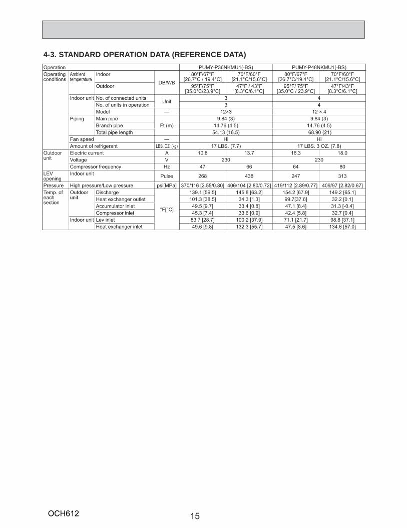
4-3. STANDARD OPERATION DATA (REFERENCE DATA)Operation PUMY-P36NKMU1(-BS) PUMY-P48NKMU1(-BS)Operatingconditions
Ambient temperature
Indoor
DB/WB
80°F/67°F[26.7°C / 19.4°C]
70°F/60°F[21.1°C/15.6°C]
80°F/67°F[26.7°C/19.4°C]
70°F/60°F[21.1°C/15.6°C]
Outdoor 95°F/75°F[35.0°C/23.9°C]
47°F / 43°F[8.3°C/6.1°C]
95°F/ 75°F[35.0°C / 23.9°C]
47°F/43°F[8.3°C/6.1°C]
Indoor unit No. of connected unitsUnit
3 4No. of units in operation 3 4Model ― 12×3 12 × 4
Piping Main pipeFt (m)
9.84 (3) 9.84 (3)Branch pipe 14.76 (4.5) 14.76 (4.5)Total pipe length 54.13 (16.5) 68.90 (21)
Fan speed ― Hi HiAmount of refrigerant LBS. OZ. (kg) 17 LBS. (7.7) 17 LBS. 3 OZ. (7.8)
Outdoor unit
Electric current A 10.8 13.7 16.3 18.0 Voltage V 230 230Compressor frequency Hz 47 66 64 80
LEV opening
Indoor unit Pulse 268 438 247 313
Pressure High pressure/Low pressure psi[MPa] 370/116 [2.55/0.80] 406/104 [2.80/0.72] 419/112 [2.89/0.77] 409/97 [2.82/0.67]Temp. of eachsection
Outdoor unit
Discharge
°F[°C]
139.1 [59.5] 145.8 [63.2] 154.2 [67.9] 149.2 [65.1]Heat exchanger outlet 101.3 [38.5] 34.3 [1.3] 99.7[37.6] 32.2 [0.1]Accumulator inlet 49.5 [9.7] 33.4 [0.8] 47.1 [8.4] 31.3 [-0.4]Compressor inlet 45.3 [7.4] 33.6 [0.9] 42.4 [5.8] 32.7 [0.4]
Indoor unit Lev inlet 83.7 [28.7] 100.2 [37.9] 71.1 [21.7] 98.8 [37.1]Heat exchanger inlet 49.6 [9.8] 132.3 [55.7] 47.5 [8.6] 134.6 [57.0]
OCH612
16
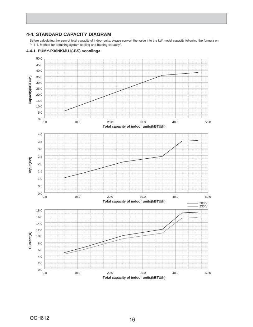
4-4. STANDARD CAPACITY DIAGRAM Before calculating the sum of total capacity of indoor units, please convert the value into the kW model capacity following the formula on "4-1-1. Method for obtaining system cooling and heating capacity".
0.0 10.0 20.0 30.0 40.0 50.00.0
5.0
10.0
15.0
20.0
25.0
30.0
35.0
40.0
45.0
50.0
0.0 10.0 20.0 30.0 40.0 50.00.0
0.5
1.0
1.5
2.0
2.5
3.0
3.5
4.0
0.0 10.0 20.0 30.0 40.0 50.00.0
2.0
4.0
6.0
8.0
10.0
12.0
14.0
16.0
18.0
208 V230 V
Cap
acity
(kB
TU/h
)
Total capacity of indoor units(kBTU/h)
Inpu
t(kW
)
Total capacity of indoor units(kBTU/h)
Cur
rent
(A)
Total capacity of indoor units(kBTU/h)
4-4-1. PUMY-P36NKMU1(-BS) <cooling>
OCH612

17
0.0 10.0 20.0 30.0 40.0 50.00.0
5.0
10.0
15.0
20.0
25.0
30.0
35.0
40.0
45.0
50.0
0.0 10.0 20.0 30.0 40.0 50.00.0
0.5
1.0
1.5
2.0
2.5
3.0
3.5
4.0
0.0 10.0 20.0 30.0 40.0 50.00.0
2.0
4.0
6.0
8.0
10.0
12.0
14.0
16.0
18.0
208 V230 V
Cap
acity
(kB
TU/h
)
Total capacity of indoor units(kBTU/h)
Inpu
t(kW
)
Total capacity of indoor units(kBTU/h)
Cur
rent
(A)
Total capacity of indoor units(kBTU/h)
4-4-2. PUMY-P36NKMU1(-BS) <heating>
OCH612
18
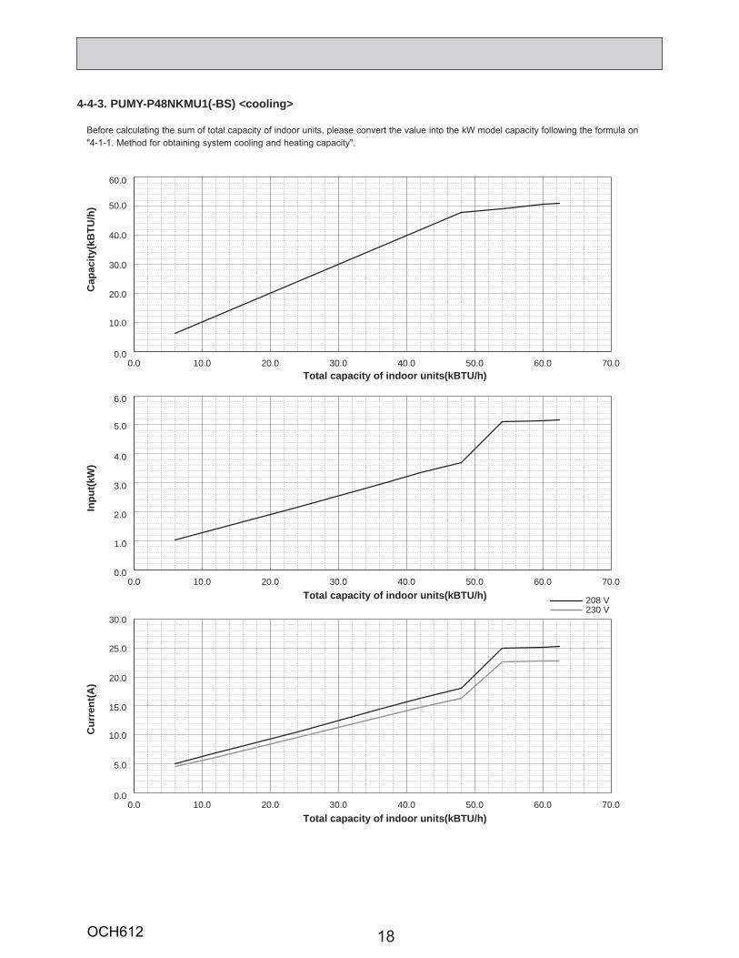
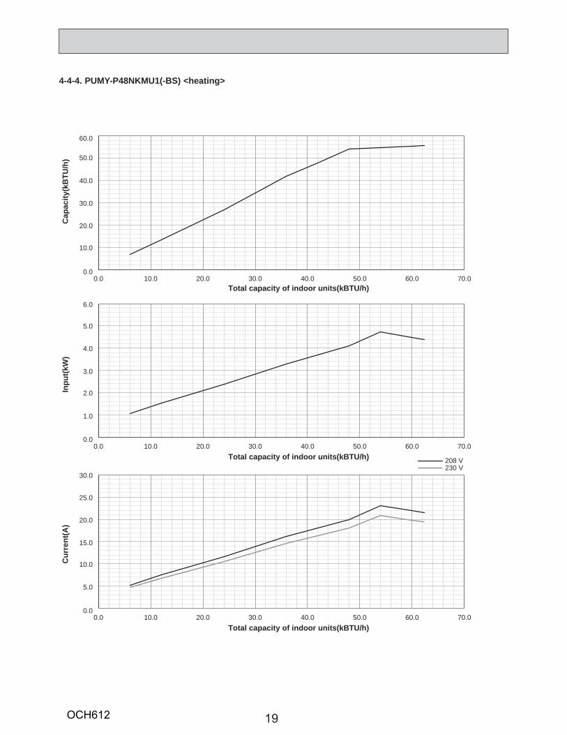
4-4-3. PUMY-P48NKMU1(-BS) <cooling>
Before calculating the sum of total capacity of indoor units, please convert the value into the kW model capacity following the formula on "4-1-1. Method for obtaining system cooling and heating capacity".
0.0 10.0 20.0 30.0 40.0 50.0 60.0 70.00.0
10.0
20.0
30.0
40.0
50.0
60.0
0.0 10.0 20.0 30.0 40.0 50.0 60.0 70.00.0
1.0
2.0
3.0
4.0
5.0
6.0
0.0 10.0 20.0 30.0 40.0 50.0 60.0 70.00.0
5.0
10.0
15.0
20.0
25.0
30.0
208 V230 V
Cap
acity
(kB
TU/h
)
Total capacity of indoor units(kBTU/h)
Inpu
t(kW
)
Total capacity of indoor units(kBTU/h)
Cur
rent
(A)
Total capacity of indoor units(kBTU/h)
OCH612
19
0.0 10.0 20.0 30.0 40.0 50.0 60.0 70.00.0
10.0
20.0
30.0
40.0
50.0
60.0
0.0 10.0 20.0 30.0 40.0 50.0 60.0 70.00.0
1.0
2.0
3.0
4.0
5.0
6.0
0.0 10.0 20.0 30.0 40.0 50.0 60.0 70.00.0
5.0
10.0
15.0
20.0
25.0
30.0
208 V230 V
Cap
acity
(kB
TU/h
)
Total capacity of indoor units(kBTU/h)
Inpu
t(kW
)
Total capacity of indoor units(kBTU/h)
Cur
rent
(A)
Total capacity of indoor units(kBTU/h)
4-4-4. PUMY-P48NKMU1(-BS) <heating>
OCH612
20
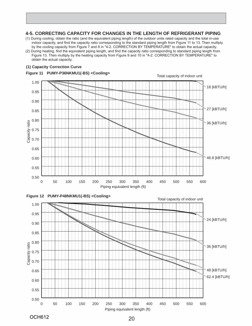
4-5. CORRECTING CAPACITY FOR CHANGES IN THE LENGTH OF REFRIGERANT PIPING(1) During cooling, obtain the ratio (and the equivalent piping length) of the outdoor units rated capacity and the total in-use
indoor capacity, and find the capacity ratio corresponding to the standard piping length from Figure 11 to 13. Then multiply by the cooling capacity from Figure 7 and 8 in "4-2. CORRECTION BY TEMPERATURE" to obtain the actual capacity.
(2) During heating, find the equivalent piping length, and find the capacity ratio corresponding to standard piping length from Figure 13. Then multiply by the heating capacity from Figure 9 and 10 in "4-2. CORRECTION BY TEMPERATURE" to obtain the actual capacity.
(1) Capacity Correction Curve
0 50 100 150 200 250 300 350 400 450 500 550 6000.50
0.55
0.60
0.65
0.70
0.75
0.80
0.85
0.90
0.95
1.00
0 50 100 150 200 250 300 350 400 450 500 550 6000.50
0.55
0.60
0.65
0.70
0.75
0.80
0.85
0.90
0.95
1.00
18 [kBTU/h]
27 [kBTU/h]
36 [kBTU/h]
Cap
acity
ratio
Piping equivalent length (ft)
Total capacity of indoor unit
Total capacity of indoor unit
Cap
acity
ratio
Piping equivalent length (ft)
46.8 [kBTU/h]
24 [kBTU/h]
36 [kBTU/h]
48 [kBTU/h]
62.4 [kBTU/h]
Figure 11 PUMY-P36NKMU1(-BS) <Cooling>
Figure 12 PUMY-P48NKMU1(-BS) <Cooling>
OCH612
21
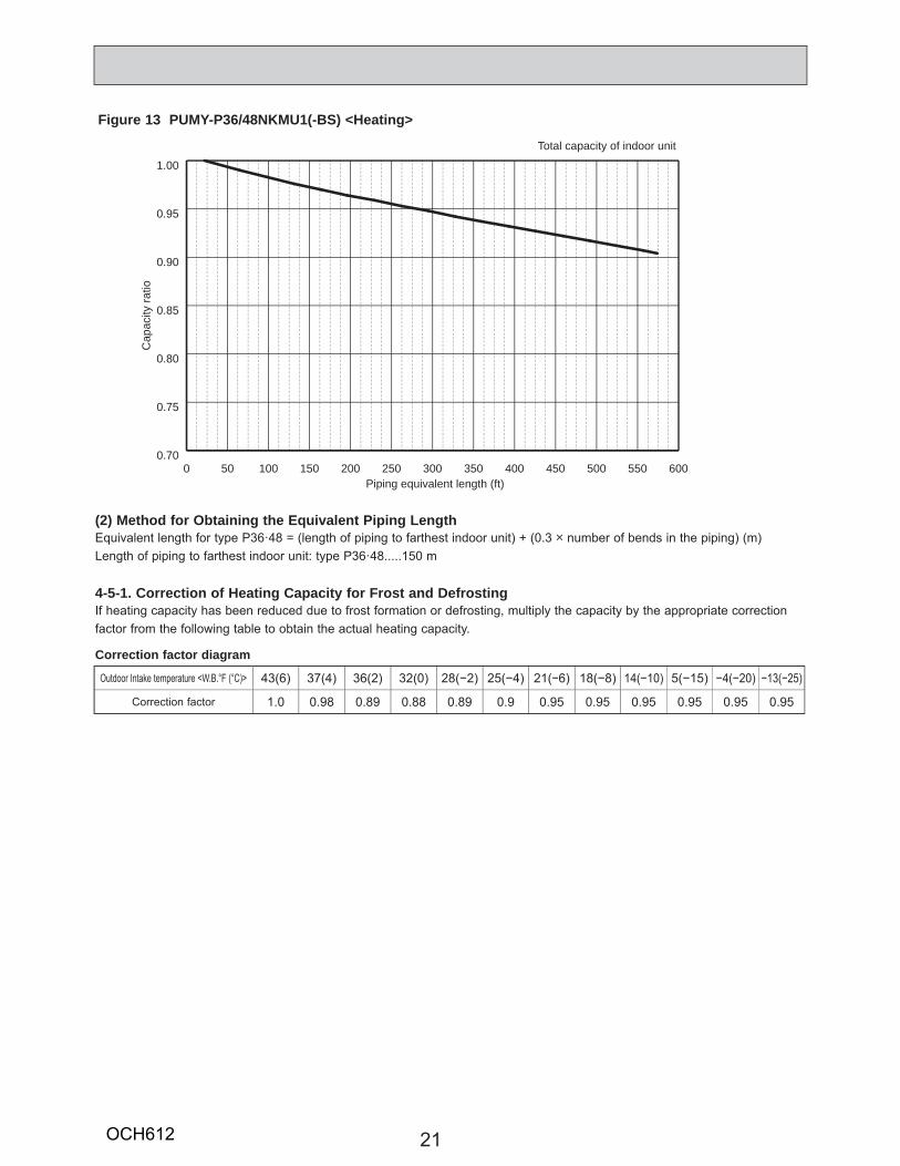
(2) Method for Obtaining the Equivalent Piping LengthEquivalent length for type P36·48 = (length of piping to farthest indoor unit) + (0.3 o number of bends in the piping) (m)Length of piping to farthest indoor unit: type P36·48.....150 m
4-5-1. Correction of Heating Capacity for Frost and DefrostingIf heating capacity has been reduced due to frost formation or defrosting, multiply the capacity by the appropriate correction factor from the following table to obtain the actual heating capacity.
Correction factor diagram
Outdoor Intake temperature <W.B.°F (°C)> 43(6) 37(4) 36(2) 32(0) 28(−2) 25(−4) 21(−6) 18(−8) 14(−10) 5(−15) −4(−20) −13(−25)
Correction factor 1.0 0.98 0.89 0.88 0.89 0.9 0.95 0.95 0.95 0.95 0.95 0.95
0 50 100 150 200 250 300 350 400 450 500 550 6000.70
0.75
0.80
0.85
0.90
0.95
1.00
Cap
acity
ratio
Piping equivalent length (ft)
Total capacity of indoor unit
Figure 13 PUMY-P36/48NKMU1(-BS) <Heating>
OCH612
22
1.5m[4.9 ft]
1m[3.3 ft]
MICROPHONE
UNIT
GROUND
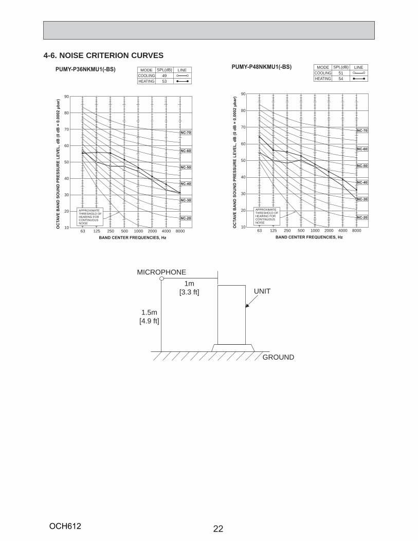
4-6. NOISE CRITERION CURVES
90
80
70
60
50
40
30
20
1063 125 250 500 1000 2000 4000 8000
APPROXIMATETHRESHOLD OFHEARING FORCONTINUOUSNOISE
OC
TAVE
BA
ND
SO
UN
D P
RES
SUR
E LE
VEL,
dB
(0 d
B =
0.0
002 μb
ar)
BAND CENTER FREQUENCIES, Hz
NC-60
NC-50
NC-40
NC-30
NC-20
NC-70
PUMY-P36NKMU1(-BS)COOLING
MODE
HEATING49
SPL(dB)
53
LINE
90
80
70
60
50
40
30
20
1063 125 250 500 1000 2000 4000 8000
APPROXIMATETHRESHOLD OFHEARING FORCONTINUOUSNOISE
OC
TAVE
BA
ND
SO
UN
D P
RES
SUR
E LE
VEL,
dB
(0 d
B =
0.0
002 μb
ar)
BAND CENTER FREQUENCIES, Hz
NC-60
NC-50
NC-40
NC-30
NC-20
NC-70
PUMY-P48NKMU1(-BS)COOLING
MODE
HEATING51
SPL(dB)
54
LINE
OCH612
23
5 OUTLINES AND DIMENSIONSPUMY-P36/48NKMU1(-BS)
Unit: mm<in>
Drain
hole
(5-{
33<1
-5/1
6>)
Botto
m p
iping
hole
(Kno
ck-O
ut)
154<6-1/16>
45<1
-25/
32>
81<3
-3/1
6>
86<3-3/8>
136<5-11/32>
160
<6-5
/16>
160
<6-5
/16>
110
<4-1
1/32
>16
0<6
-5/1
6>
Righ
t pipi
ng ho
le(K
nock
-Out)
Cond
uit ho
le({
24<1
5/16>
Knoc
k-Out)
Cond
uit ho
le( {
37<1
-15/32
>Kno
ck-O
ut)
Righ
t tru
nking
hole
(Kno
ck-O
ut)
92<3
-5/8
>
60<2
-3/8
>
5<3/16>60<2-3/8>
55<2
-3/1
6>
53<2
-3/3
2>
92<3-5/8>
26<1-1/32>27<1-1/16>
29<1
-5/3
2>
73<2-7/8>
{92
<3-5
/8>
Min
. 150
mm
<5-2
9/32
>M
in. 1
000m
m<3
9-3/
8>
Cond
uit ho
le({
37<1
-15/32
>Kno
ck-O
ut)Fr
ont t
runk
ing h
ole(K
nock
-Out
)
Fron
t pipi
ng ho
le(K
nock
-Out)
Cond
uit ho
le({
24<1
5/16>
Knoc
k-Out)
55<2-3/16> 27<1-1/16>
92<3
-5/8
>
75<2
-15/
16>
73<2-7/8> 26<1-1/32>
55<2
-3/1
6>
60<2-3/8>
5<3/16>
60<2
-3/8
>
{92
<3-5
/8>
FREE
Min
. 15m
m<1
9/32
>M
in. 1
5mm
<19/
32>
Cond
uit ho
le({
24<1
5/16>
Knoc
k-Out)
Cond
uit ho
le({
37<1
-15/32
>Kno
ck-O
ut)
Rear
trun
king h
ole(K
nock
-Out)
Rear
pipin
g hole
(Kno
ck-O
ut)
75<2
-15/
16>
60<2-3/8>
92<3
-5/8
>
73<2-7/8> 26<1-1/32>
27<1-1/16>55<2-3/16>
55<2
-3/1
6>
5<3/16>
60<2
-3/8
>
{92
<3-5
/8>
1/2 in
ch C
ondu
itatt
achm
ent
{22.2
<7/8>
{27.8
<1-3/
32>
Whe
n in
stal
ling
the
cond
uit.
Set
the
atta
chm
ent t
o th
e in
ner s
ide
of e
ach
pane
l.
3/4 in
ch C
ondu
itatt
achm
ent
Scale
1:5
24.7<31/32>
5<3/16>
60<2
-3/8
>22
.5<7
/8>
100
<3-1
5/16
>
Install
ation F
eet
2-U
Shap
ed no
tched
holes
(Fou
ndati
on B
olt M
10<W
3/8>)
2-12
×36 O
val h
oles
(Fou
ndati
on B
olt M
10<W
3/8>)
Side
Air
Inta
ke
Rear
Air
Inta
ke
Air D
ischa
rge
60.5
<2-3
/8>
42<1
-21/
32>
19<3/4>
600
<23-
5/8>
330<13>
225
<8-2
7/32
>22
5<8
-27/
32>
28<1-3/32>
70<2
-3/4
>
417<16-13/32>
25<1>
370<14-9/16>
39.5
<1-9
/16>
0056<2
-7/3
2>
0 53<2
-3/3
2>
Rear
pipi
ng co
ver
Fron
t pipi
ng co
ver
Air i
ntak
e
Side
Air
Inta
ke
21Hand
le for
mov
ing
Servi
ce pa
nel
Grou
nd fo
r the
tran
smiss
ion lin
eGr
ound
for c
once
ntra
tion
cont
rolFo
r con
cent
ratio
nco
ntro
lFo
r the
tra
nsm
issio
n lin
eFo
r the
po
wer s
uppl
y
Term
inal
con
nect
ion
From
left
to ri
ght
Hand
le for
mov
ingG
roun
d fo
r the
pow
er s
uppl
y("
GR
"mar
king
pos
ition
)
*1485<19-3/32>
1050
<41-
11/3
2>
362
<14-
1/4>
*1426<16-25/32>
1067<42>
26<1-1/32>
632<24-7/8> 369<14-17/32>
1338<52-11/16>
Hand
le fo
rm
oving
Han
dle
for
mov
ing
Rear
Air
Inta
ke
21Re
frigera
nt GA
S pipe
conn
ection
(FLA
RE)
{ 15.8
8 (5/8
F)Re
frigera
nt LIQ
UID pip
e con
nectio
n (FL
ARE)
{ 9.52
(3/8F
)*1
Ind
ication
of ST
OP VA
LVE c
onne
ction lo
cation
.
4 PIPI
NG-W
IRING
DIRE
CTION
S3 F
OUND
ATIO
N BO
LTS
2 SER
VICE
SPA
CE1 F
REE S
PACE
(Arou
nd th
e unit
)
Max.<Fou
ndat
ion
bolt
heig
ht>
FOUN
DATIO
N
Servic
e spa
ce
Min. Min.
Min.
Min.
15<1
9/32
>
500
<19-
11/1
6>
500<19-11/16>
150<5-29/32>
30<1-3/16>
Piping
Knoc
k-Out
Hole
Detai
ls
Exam
ple of
Notes
The d
iagra
m be
low sh
ows a
basic
exam
ple.
Expla
ntion
of pa
rticula
r deta
ils ar
egiv
en in
the i
nstal
lation
man
uals
etc.
Dime
nsion
s of s
pace
need
edfor
servi
ce ac
cess
are
show
n in t
he be
low di
agra
m.
Pleas
e sec
ure th
e unit
firml
ywit
h 4 fo
unda
tion (
M10<
W3/8>
) bolt
s.(B
olts a
nd w
ashe
rs mu
st be
purch
ased
loca
lly.)
Pipi
ng a
nd w
iring
con
nect
ions
can
be m
ade
from
4 d
irect
ions
:FR
ONT
, Rig
ht, R
ear a
nd B
elow
.
OCH612
24
6
Cautions when Servicing
! WARNING: When the main supply is turned off, the voltage [340 V] in the main capacitor will drop to 20 V in approx. 2 minutes (input voltage: 230 V). When servicing, make sure that LED1, LED2 on the outdoor multi controller circuit board goes out, and then wait for at least 1 minute.Components other than the outdoor circuit boards may be faulty: Check and take corrective action, referring to the service manual. Do not replace the outdoor circuit boards without checking.
1 2 3 4 5 6 7 8
〔Example〕 When the compressor and SV1 are on during cooling operation.
Bit
Indication
1Compressor operated
2
52C
3
21S4
4
SV1
5
(SV2)
6
ー
7
ー
8
Always lit
During normal operation The LED indicates the drive state of outdoor unit.
When fault requiring inspection has occurred The LED alternately indicates the check code and the address of the unit in which the fault has occurred.
NOTES: 1.Refer to the wiring diagrams of the indoor units for details on wiring of each indoor unit.2.Self-diagnosis function The indoor and outdoor units can be diagnosed automatically using the self-diagnosis switch (SW1) and LED indication (LED1, LED2) found on the outdoor multi controller circuit board. LED indication : Set all contacts of SW1 to OFF.
SYMBOL NAMETB1 Terminal Block 〈Power Supply〉TB3
TB7
MC Motor For CompressorMF1,MF2 Fan Motor
LEV-A,LEV-B Linear Expansion Valve
21S4
SV1
TH3 Thermistor〈Outdoor Liquid Pipe〉TH2 Thermistor〈Hic Pipe〉
TH4 Thermistor〈Compressor〉TH6 Thermistor〈Suction Pipe〉TH7TH8
Thermistor〈Ambient〉Thermistor〈Heat Sink〉
63H High Pressure Switch63HS High Pressure Sensor63LS Low Pressure Sensor
DCLP.B. Power Circuit Board
Connection Terminal〈U/V/W-Phase〉U/V/W
MULTI.B.
Fuse〈UL6.3A250V〉F1,F2
Switch〈Display Selection〉SW1Switch〈Function Selection〉SW2Switch〈Test Run〉SW3Switch〈Model Selection〉SW4Switch〈Function Selection〉SW5Switch〈Function Selection〉SW6Switch〈Function Selection〉SW7Switch〈Model Selection〉SW8Switch〈Function Selection〉SW9Switch〈Unit Address Selection, ones digit〉SWU1Switch〈Unit Address Selection, tens digit〉SWU2
LED〈Operation Inspection Display〉LED1,LED2LED〈Power Supply to Main Microcomputer〉LED3
Multi Controller Circuit Board
Connector〈Connection For Option〉SSConnector〈Connection For Option〉CN3D
CNS1
Connector〈Centralized Control Transmission Line〉CNS2
Connector〈Connection For Option〉CN3SConnector〈Connection For Option〉CN3NConnector〈Connection For Option〉CN51
RelayX501~505M-NET P.B. M-NET Power Circuit Board
TB1
Connection Terminal〈L-Phase〉LIConnection Terminal〈N-Phase〉NI
EI,E2,E3,E4Power ModuleIGBTConnection Terminal〈Reactor〉DCL1,DCL2
Reactor
Terminal Block 〈Centralized Control Transmission Line〉
Terminal Block 〈Indoor/Outdoor Transmission Line〉
Connector〈Indoor/Outdoor Transmission Line〉
ConnectionTerminal〈Electrical Parts Box〉
ConnectionTerminal〈Electrical Parts Box〉
Solenoid Valve Coil〈4-Way Valve〉
Solenoid Valve Coil〈Bypass Valve〉
MODELS
PUMY-P36NKMU1
PUMY-P48NKMU1
SW4 SW8*1 MODEL SELECTION
*2 Use copper supply wires.Utilisez des fils d' slimentation en cuivre.
The black square( )indicates a switch position.
ONOFF
1 2 3 4 5 6
ONOFF
1 2
ONOFF
1 2 3 4 5 6
ONOFF
1 2
RD
RD
YE
YE
P. B.
BK WH
WH
WH
U
U
V
V
W
W
RD
MC
MS3~
M1
M2
S
TB3
TO INDOOR UNITCONNECTING WIRES30VDC(Non-polar)
FOR CENTRALIZEDCONTROL30VDC(Non-polar)
M1
M2
S
TB7
2
2
GNYE
BU
RDPOWER SUPPLY208/230VAC60Hz
TB1
L1
L2
GR
CN51(WH)
SW6
SW2SW8SW1
SW7SW3SW4
*1
*2
*1
SW5SWU2 SWU1 SW9
TRANSLED1
CN2(RD)
CN4(WH)
LED3
CN3D(WH)
CN3S(RD)
CN3N(BU)
CN1(WH)
TB1BK
CNDC(PK)
t゜ t゜ t゜ t゜
LEV-BM
1 41
3
3
1 3 1 3 1 3
CN52(RD)1 3
31
12
2 21 11 2
1 2
2
2 1 2 1
2
31 21
TH7 TH6 TH3 TH463HS63H
1
7
7
1 5
1 5TH7/6(RD)
CNLVB(RD)
TH3(WH)
TH4(WH)
t゜
TH2
t゜
TH8
TH2(BK)
63HS(WH)
1 3 1 3
63LS
63LS(BU)
63H(YE)
MULTI. B.
LED2
M-NET P.B.
52C(BK)
31 31 31
X505
21S4(GN)
SV1(GY)
SV2(BU)
SS(WH)
21S4 SV1
CNAC(RD)
CNS1(RD)
CNS2(YE)
F1
F2X504
X503
X502
X501
CN102(WH)
CN2(WH)
4
4
1
1
CN40(WH)4 1
5 3 1
CN41(WH)4 1
4
2
3
CN2(RD)
CN4(WH)
1 2
2
1
7
7
22
CNDC(PK)3 1
2
N2
P2+
~
~
-
+
DCL
DCL2 DCL1
IGBT
E I
E 4
E2CN
AC1
(W
H)L IN I
BK
BK
21
3
CNAC
2(
RD)
1
3
E3
BK
2
is the switch position.
LEV-AM
1 5CNLVA(WH)
CN52C(RD)1 3
3
52C
52C
BK
17
CNF1(WH)
1 7
CNF2(WH)
MS3~
MF1
MS3~
MF2
WIRING DIAGRAM
PUMY-P36/48NKMU1(-BS)
OCH612
25
7 NECESSARY CONDITIONS FOR SYSTEM CONSTRUCTION
7-1. TRANSMISSION SYSTEM SETUP
01 2 3 4
56789
01 2 3 4
56789
01 2 3 4
56789
01 2 3 4
56789
01 2 3 4
56789
01 2 3 4
56789
051 0
1 2 3 45
67890
1 2 3 45
6789
056
001
01 2 3 4
56789
01 2 3 4
56789
010
101
10
1 2 3 45
67890
1 2 3 45
6789
01 2 3 4
56789
01 2 3 4
56789
002
102
104
154
11
11
11
01 2 3 4
56789
01 2 3 4
56789
009
01 2 3 4
56789
01 2 3 4
56789
008
01 2 3 4
56789
01 2 3 4
56789
003
01 2 3 4
56789
01 2 3 4
56789
01 2 3 4
56789
01 2 3 4
56789
01 2 3 4
56789
01 2 3 4
56789
007
01 2 3 4
56789
01 2 3 4
56789
006
01 2 3 4
56789
01 2 3 4
56789
01 2 3 4
56789
01 2 3 4
56789
01 2 3 4
56789
01 2 3 4
56789
004
01 2 3 4
56789
01 2 3 4
56789
01 2 3 4
56789
01 2 3 4
56789
005
1 A
tran
smis
sion
wire
mus
t be
co
nnec
ted
to e
ach
refri
gera
nt
syst
em (o
utdo
or a
nd in
door
).
2 S
et a
ddre
sses
:
Out
door
uni
t ....
......
....0
51–1
00
Indo
or u
nit .
......
......
....0
01–0
50
Rem
ote
cont
rolle
r ....
.101
–200
3 P
UM
Y ha
s no
100
s di
git s
witc
h.
The
addr
ess
auto
mat
ical
ly b
ecom
e
"100
" if i
t is
set a
s "0
1–50
".
Rem
ote
cont
rolle
rR
emot
eco
ntro
ller
Rem
ote
cont
rolle
rR
emot
eco
ntro
ller
105
Rem
ote
cont
rolle
r
157
Rem
ote
cont
rolle
r10
7R
emot
eco
ntro
ller
For c
entra
lized
man
agem
ent
For C
ity M
ulti
indo
or u
nit
Add
ress
SW
Add
ress
SW
Add
ress
SW
Add
ress
SW
Add
ress
SW
Pip
ing
Out
door
uni
t
Out
door
uni
t
Indo
or u
nit
Indo
or u
nit
Indo
or u
nit
Indo
or u
nit
Indo
or u
nit
Indo
or u
nit
Indo
or u
nit
Indo
or u
nit
Indo
or u
nit
Indo
or u
nit
Add
ress
SW
Add
ress
SW
Add
ress
SW
Add
ress
SW
Add
ress
SW
Add
ress
SW
Add
ress
SW
Add
ress
SW
Add
ress
SW
Add
ress
SW
Add
ress
SW
Add
ress
SW
For c
entra
lized
man
agem
ent
For C
ity M
ulti
indo
or u
nit
Tran
smis
sion
wire
2
1
OCH612
26
7-2. Special Function Operation and Settings for M-NET Remote Controller
7-3. REFRIGERANT SYSTEM DIAGRAM PUMY-P36/48NKMU1(-BS)
Solenoidvalve (SV1)
High pressuresensor (63HS)
High pressureswitch (63H)
Low pressuresensor(63LS)
Oil separator
Service port
Strainer
Distributor
Compressor
Refrigerant piping specifications <dimensions of flared connector> Capillary tube for oil separator : [2.5 o [0.8 o L1000
Capacity Item Liquid piping Gas piping
P06, P08, P12, P15, P18
P24, P27, P36, P48, P54
P36, P48
Indoor unit
Outdoor unit
1/4 <[6.35>
3/8 <[9.52>
3/8 <[9.52>
1/2 <[12.7>
5/8 <[15.88>
5/8 <[15.88>
Thermistor (TH4)<Compressor>
Thermistor (TH7)<Ambient>
<Outdoor liquid pipe>Thermistor (TH3)
Unit: in <mm>
Ball valve
StrainerRefrigerant Gas pipe
4-way valve
Check valve<Low pressure>
Thermistor (TH6)<Suction pipe>
Check valve<High pressure>
Strainer
Strainer Strainer
Strainer
Thermistor (TH2)<Hic pipe>
RefrigerantLiquid pipe
Stop valve
Service port
Capillary tube
Accumulator
Strainer
Refrigerant flow in cooling Refrigerant flow in heating
For the detailed procedure of "group settings" and "paired settings", refer to the remote controller's manuals.
OCH612
27
7-4. SYSTEM CONTROL7-4-1. Example for the System• Example for wiring control cables, wiring method and address setting, permissible lengths, and the prohibited items are listed
in the standard system with detailed explanation.
A. Example of a M-NET remote controller system (address setting is necessary.)Example of wiring control cables Wiring Method and Address Setting
• 1 M-NET remote controller for each M-NET control indoor unit.
• There is no need for setting the 100 position on the M-NET remote controller.
1. Standard operation
2. Operation using 2 M-NET remote controllers
• Using 2 M-NET remote controllers for each M-NET control indoor unit.
a. Use feed wiring to connect terminals M1 and M2 on transmission cable block (TB3) for the outdoor unit (OC) to terminals M1 and M2 on the transmission cable block (TB5) of each M-NET control indoor unit (M-IC). Use non-polarized 2-core wire.
b. Connect terminals M1 and M2 on transmission cable terminal block (TB5) for each indoor unit with the termi-nal block (TB6) for M-NET the remote controller (M-NET RC).
c. Set the address setting switch (on outdoor unit P.C.B) as shown below.
3. Group operation
• Multiple M-NET control indoor units operated together by 1 M-NET remote controller
a. Same as above ab. Same as above bc. Set address switch (on outdoor unit P.C.B) as
shown below.
a. Same as above ab. Connect terminals M1 and M2 on transmission cable termi-
nal block (TB5) of the M-IC main unit with the most recent address within the same M-NET control indoor unit (M-IC) group to terminal block (TB6) on the M-NET remote controller.
c. Set the address setting switch (on outdoor unit P.C.B) as shown below.
d. Use the M-NET control indoor unit (M-IC) within the group with the most functions as the M-IC (Main) unit.
Combinations of 1 through 3 above are possible.
TB5 TB15
(01)
(101)
M-IC(Main)
TB3 TB7
(51)
OC
TB5 TB15
(02)
M-IC(Sub)
M-NET RC
1 2
A B
M1 M2 S M1 M2 SM1 M2 S 1 2M1 M2 S
Group A
TB5 TB15
(01)
(101)M-NET RC
(Main)
(151)
M-IC
TB3 TB7
(51)
OC
TB5 TB15
(02)
M-IC
M-NET RC(Sub)
(102)M-NET RC
(Main)
(152)M-NET RC
(Sub)
1 2M1 M2 S M1 M2 SM1 M2 S 1 2M1 M2 S
A B A B A B A B
TB51 2
TB15
(01)
(101)
M-IC
A B
M1 M2
TB3S
TB7
(51)
OCL1
L3
L2
TB5 TB15
(02)
M-IC
M-NET RC
(102)M-NET RC
l1
l2
M1 M2 SM1 M2 S 1 2M1 M2 S
A B Unit Range Setting Method
M-NET control indoor unit (M-IC) 001 to 050 —
Outdoor unit (OC) 051 to 100 Use the smallest address of all the indoor unit plus 50.
M-NET Remote controller (M-NET RC) 101 to 150 Indoor unit address plus 100
Unit Range Setting MethodM-NET control
indoor unit (M-IC) 001 to 050 —
Outdoor unit (OC) 051 to 100 Use the smallest address of all the indoor units plus 50.
Main M-NET Remote Controller
(M-NET RC)101 to 150 Indoor unit address plus 100
Sub M-NET Remote Controller
(M-NET RC)151 to 200 Indoor unit address plus 150
Unit Range Setting Method
M-IC (Main) 001 to 050Use the smallest address within the same group of M-NET control indoor units.
M-IC (Sub) 001 to 050
Use an address, other than that of the M-IC (Main) from among the units within the same group of indoor units. This must be in sequence with the M-IC (Main).
Outdoor unit 051 to 100 Use the smallest address of all the M-NET control indoor units plus 50.
Main M-NET Remote Controller
(M-NET RC)101 to 150 Set at an M-IC (Main) address
within the same group plus 100.
OCH612
28
• Name, Symbol and the Maximum Remote controller Units for Connection
Permissible Lengths Prohibited items
Longest transmission cable lengthAWG 16 [1.25 mm²]L1 + L2, L3 + L1 [ 656 ft [200 m]M-NET Remote controller cable length1. If AWG 20 to AWG 16 [0.5 to 1.25 mm²]R1, R2 [ 33ft [10 m]
2. If the length exceeds 33ft [10 m], the exceeding section should be AWG 16 [1.25 mm²] and that section should be a value within the total extension length of the transmission cable and maxi-mum transmission cable length. (L3)
Same as above
Same as above
1 Use the M-NET control indoor unit (M-IC) address plus 150 as the sub M-NET remote controller address. In this case, it should be 152.
2 3 or more M-NET remote controllers (M-NET RC) cannot be connected to 1 M-NET control indoor unit.
1 The M-NET remote controller address is the M-NET control indoor unit main address plus 100. In this case, it should be 101.
• M-NET remote controller (M-NET RC) and MA remote controller (MA RC) cannot be used together.
• Do not connect anything with TB15 of M-NET control indoor unit (M-IC).
Name Symbol Maximum units for connectionOutdoor unit OC —M-NET control
Indoor unit M-IC 1 OC unit can be connected to 1 to 7 (P36) / 1 to 10 (P48) M-IC unitsM-NET remote
controller M-NET RC Maximum 2 M-NET RC for 1 indoor unit, Maximum 12 M-NET RC for 1 OC
NO
TB5 TB15
(01)
(101)
M-IC
TB3 TB7
(51)
OC
TB5 TB15
(02)
M-NET RC
TB15
MA-RC
1 2
A B
M1 M2 S M1 M2 SM1 M2 S 1 2M1 M2 S
A B
M-IC
NO NO
TB5 TB15
(01)
(101)M-NET RC
(Main)
(151)
M-IC
TB3 TB7
(51)
OC
TB5 TB15
(02)
M-IC
M-NET RC(Sub)
(102)M-NET RC
(Main)
(104)2M-NET RC
1 2
A B
M1 M2 S M1 M2 SM1 M2 S 1 2M1 M2 S
A B A B A BA B
(103)1M-NET RC
(Sub)
NO
TB5 TB15
(01)
(102)
M-IC(Main)
TB3 TB7
(51)
OC
TB5 TB15
(02)
M-IC(Sub)
M-NET RC
1 2
A B
M1 M2 S M1 M2 SM1 M2 S 1 2M1 M2 S
OCH612
29
B. Example of a group operation system with 2 or more outdoor units and a M-NET remote controller.(Address settings are necessary.)
Exa
mpl
es o
f Tra
nsm
issi
on C
able
Wiri
ngW
iring
Met
hod
Add
ress
Set
tings
a. Always use shielded wire when making connections between the outdoor unit (OC) and the M-NET control indoor unit (M-IC), as well for all OC-OC, and IC-IC wiring intervals.
b. Use feed wiring to connect terminals M1 and M2 and the ground terminal on the transmission cable terminal block (TB3) of each outdoor unit (OC) to terminals M1 and M2 on the terminal S on the transmission cable terminal block of the M-NET control indoor unit (M-IC).
c. Connect terminals M1 and M2 on the transmission cable terminal block of the M-NET control indoor unit (M-IC) that has the most recent address within the same group to the terminal block on the M-NET remote controller (M-NET RC).
d. Connect together terminals M1, M2 and terminal S on the terminal block for centralized control (TB7) for the outdoor unit (OC).
e. DO NOT change the jumper connector CN41 on outdoor multi controller circuit board.f. The earth processing of S terminal for the centralized control terminal block (TB7) is unnecessary. Connect the termi-
nal S on the power supply unit with the earth.g. Set the address setting switch as follows.
h. The group setting operations among the multiple M-NET control indoor units is done by the M-NET remote controller (M-NET RC) after the electrical power has been turned on.
Unit Range Setting MethodM-IC (Main) 01 to 50 Use the smallest address within the same group of M-NET control indoor units.
M-IC (Sub) 01 to 50 Use an address, other than the M-IC (Main) in the same group of M-NET control indoor units. This must be in sequence with the M-IC (Main).
Outdoor Unit 51 to 100 Use the smallest address of all the M-NET control indoor units plus 50.The address automatically becomes “100” if it is set as “01–50”.
Main M-NET Remote Controller 101 to 150 Set at an M-IC (Main) address within the same group plus 100.Sub M-NET Remote Controller 151 to 200 Set at an M-IC (Main) address within the same group plus 150.
MA Remote Controller — Address setting is not necessary. (Main/sub setting is necessary.)
A
B
C
E
D
TB7TB3
M-IC(51)
TB5
M-NET RC
(01)
M-IC
TB5
(03)
M-IC
TB5
(02)
M-IC
TB5
(04)
M-IC
TB5
(05)
TB5
(07)
IC
TB5
(06)
L2
L1
(101) (105)
(104)
(155)
OC
TB7
(53)
OC
3
Power SupplyUnit
System controller
L3
L6
L7
L4
L5
2
4
1
A : GroupB : GroupC : GroupD : Shielded WireE : Sub M-NET Remote Controller( ): Address example
r
rr r
M1 M2 S M1 M2 S M1 M2 S M1 M2 S
A BA BA B
M1 M2 S M1 M2 S M1 M2 SSM1 M2 STB3
M1 M2 S
M1 M2 S
A B
M1 M2
M1 M2 S M1 M2 S
NOM-IC
M-NET RC
M-NET RC M-NET RC
OCH612
30
• Name, Symbol, and the Maximum Units for ConnectionP
erm
issi
ble
Leng
thP
rohi
bite
d ite
ms
• Longest length via outdoor units : L1+L2+L3+L4, L1+L2+L3+L5, L1+L2+L6+L7 [ 1640 ft [500 m] (AWG 16 [1.25 mm² ])• Longest transmission cable length : L1, L3+L4, L3+L5, L2+L6, L7 [ 656 ft [200 m] (AWG 16 [1.25 mm²])• M-NET Remote controller cable length : R1,R2, R2+R3, R4 [ 33 ft [10 m] (AWG 20 to AWG 16 [0.5 to 1.25 mm²])
If the length exceeds 33 ft [10 m], use a AWG 16 [1.25 mm²] shielded wire. The length of this section (L8) should be included in the calculation of the maximum length and overall length.
• Never connect together the terminal blocks (TB5) for transmission wires for M-NET control indoor units (M-IC) that have been connected to different outdoor units (OC).
• Set all addresses to ensure that they are not overlapped.• M-NET remote controller and MA remote controller cannot be connected with the M-NET control indoor unit of the same
group wiring together.
A
B
C
E
D
M-IC(51)
TB5
M-NET RC
(01)
TB5
(03)
M-IC
TB5
(02)
TB5
(04)
M-IC
TB5
(05)
TB5
(07)
M-IC
TB5
(06)
(101) (105)
(104)
(155)
OC
(53)OC
Power SupplyUnit
A : GroupB : GroupC : GroupD : Shielded WireE : Sub M-NET Remote Controller( ): Address example
TB7TB3M1 M2 S
TB7
M1 M2 SM1 M2 S
TB3
M1 M2 S
M1 M2 S
M1 M2 S M1 M2 S M1 M2 S M1 M2 S
M1 M2 S M1 M2 S M1 M2 S
A B A B A B
A B
M1 M2 S
System controller
NONO
M-IC M-IC M-IC
M-NET RC M-NET RC
M-NET RC
OCH612
31
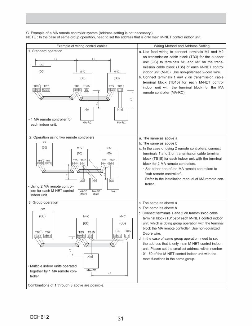
C. Example of a MA remote controller system (address setting is not necessary.)NOTE : In the case of same group operation, need to set the address that is only main M-NET control indoor unit.
Example of wiring control cables Wiring Method and Address Setting
• 1 MA remote controller for each indoor unit.
1. Standard operation
2. Operation using two remote controllers
• Using 2 MA remote control-lers for each M-NET control indoor unit.
a. Use feed wiring to connect terminals M1 and M2 on transmission cable block (TB3) for the outdoor unit (OC) to terminals M1 and M2 on the trans-mission cable block (TB5) of each M-NET control indoor unit (M-IC). Use non-polarized 2-core wire.
b. Connect terminals 1 and 2 on transmission cable terminal block (TB15) for each M-NET control indoor unit with the terminal block for the MA remote controller (MA-RC).
3. Group operation
• Multiple indoor units operated together by 1 MA remote con-troller.
a. The same as above ab. The same as above bc. In the case of using 2 remote controllers, connect
terminals 1 and 2 on transmission cable terminal block (TB15) for each indoor unit with the terminal block for 2 MA remote controllers.· Set either one of the MA remote controllers to "sub remote controller".
Refer to the installation manual of MA remote con-troller.
a. The same as above ab. The same as above bc. Connect terminals 1 and 2 on transmission cable
terminal block (TB15) of each M-NET control indoor unit, which is doing group operation with the terminal block the MA remote controller. Use non-polarized 2-core wire.
d. In the case of same group operation, need to set the address that is only main M-NET control indoor unit. Please set the smallest address within number 01–50 of the M-NET control indoor unit with the most functions in the same group.
Combinations of 1 through 3 above are possible.
MA-RC
TB5 TB15
(00)
M-IC
TB3 TB7
(00)
OC
TB5 TB15
(00)
M-IC
r7
r8
M1 M2 S M1 M2 S M1 M2 S
A B
1 2M1 M2 S1 2
MA-RC (Main)
TB5 TB15
(00)
M-IC
TB3 TB7
(00)
OC
TB5 TB15
(00)
M-IC
MA-RC(Sub)
MA
r3
r4
r5
M1 M2 S M1 M2 S 1 2M1 M2 S 1 2M1 M2 S
A B A B A B
TB5 TB15
(00)
M-IC
TB3 TB7
(00)
OC
L1 L2
TB5 TB15
(00)
M-IC
MA-RCMA-RC
r1
r2
M1 M2 S M1 M2 S 1 2M1 M2 S 1 2M1 M2 S
A BA B
OCH612
32
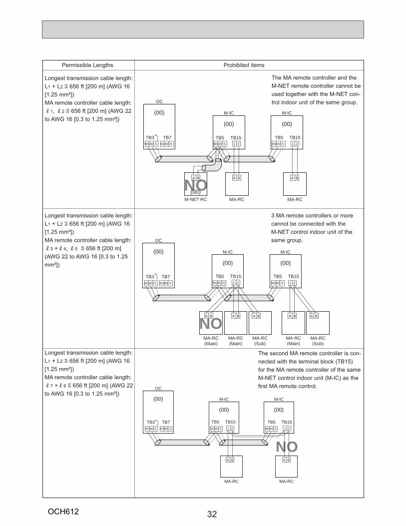
Permissible Lengths Prohibited items
Longest transmission cable length:L1 + L2 [ 656 ft [200 m] (AWG 16 [1.25 mm²])MA remote controller cable length:R1, R2 [ 656 ft [200 m] (AWG 22 to AWG 16 [0.3 to 1.25 mm²])
Longest transmission cable length:L1 + L2 [ 656 ft [200 m] (AWG 16 [1.25 mm²])MA remote controller cable length:R3 +R4, R5 [ 656 ft [200 m] (AWG 22 to AWG 16 [0.3 to 1.25 mm²])
Longest transmission cable length:L1 + L2 [ 656 ft [200 m] (AWG 16 [1.25 mm²])MA remote controller cable length:R7 +R8 [ 656 ft [200 m] (AWG 22 to AWG 16 [0.3 to 1.25 mm²])
The MA remote controller and the M-NET remote controller cannot be used together with the M-NET con-trol indoor unit of the same group.
3 MA remote controllers or more cannot be connected with the M-NET control indoor unit of the same group.
The second MA remote controller is con-nected with the terminal block (TB15) for the MA remote controller of the same M-NET control indoor unit (M-IC) as the first MA remote control.
NO
MA-RC
(00)
M-IC(00)
OC
MA-RC
(00)
M-IC
TB51 2
TB15
A B
M1 M2
TB3S
TB7 TB5 TB15M1 M2 SM1 M2 S 1 2M1 M2 S
A B
MA-RC(Main)
TB5 TB15
(00)
M-IC
TB3 TB7
(00)
OC
TB5 TB15
(00)
M-IC
MA-RC(Sub)
MA-RC(Main)
MA-RC(Sub)
MA-RC(Main)
1 2M1 M2 S M1 M2 SM1 M2 S
A B A B A B A B A B
1 2M1 M2 S
NO
NO
TB5 TB15TB3 TB7
(00)
OC
TB5 TB15
(00)
M-IC
MA-RCMA-RCM-NET RC
1 2
A B
M1 M2 S M1 M2 SM1 M2 S 1 2M1 M2 S
A BA B
(00)
M-IC
(00)
OCH612
33
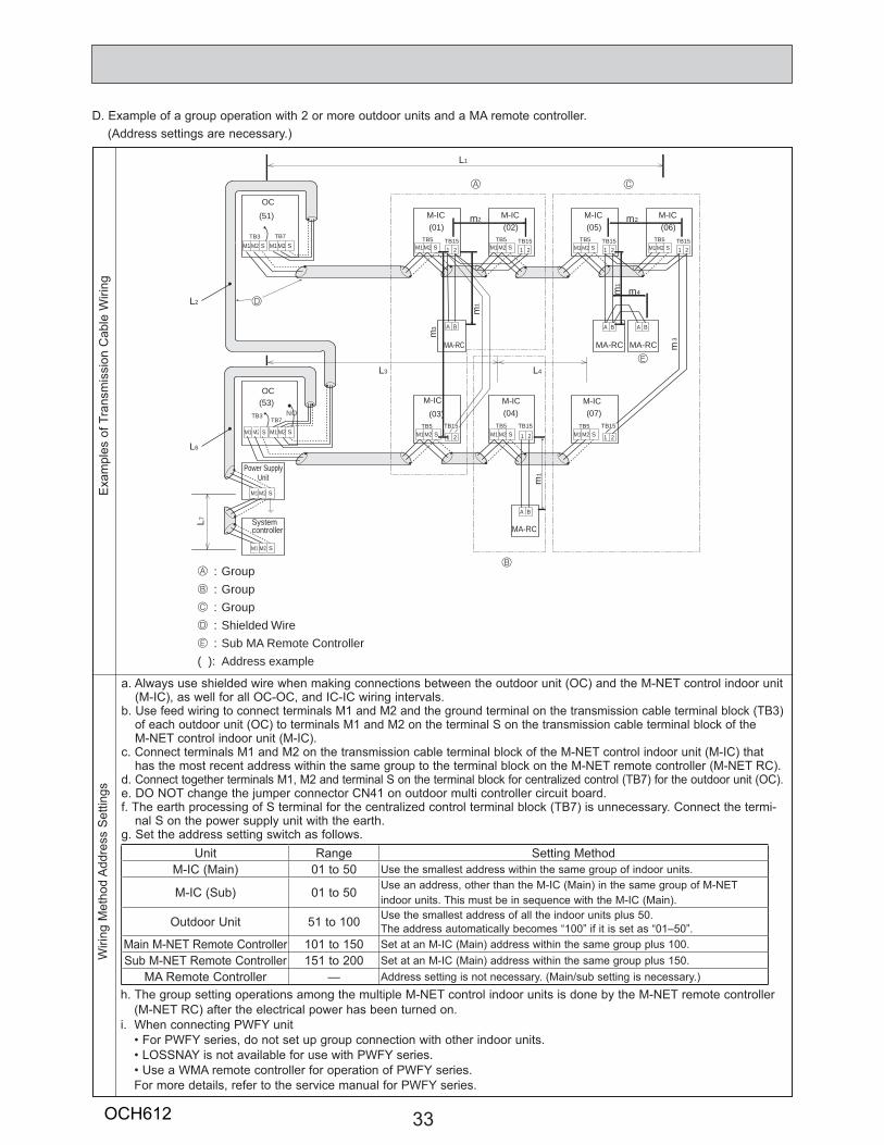
D. Example of a group operation with 2 or more outdoor units and a MA remote controller.(Address settings are necessary.)
Exa
mpl
es o
f Tra
nsm
issi
on C
able
Wiri
ngW
iring
Met
hod
Add
ress
Set
tings
a. Always use shielded wire when making connections between the outdoor unit (OC) and the M-NET control indoor unit (M-IC), as well for all OC-OC, and IC-IC wiring intervals.
b. Use feed wiring to connect terminals M1 and M2 and the ground terminal on the transmission cable terminal block (TB3) of each outdoor unit (OC) to terminals M1 and M2 on the terminal S on the transmission cable terminal block of the M-NET control indoor unit (M-IC).
c. Connect terminals M1 and M2 on the transmission cable terminal block of the M-NET control indoor unit (M-IC) that has the most recent address within the same group to the terminal block on the M-NET remote controller (M-NET RC).
d. Connect together terminals M1, M2 and terminal S on the terminal block for centralized control (TB7) for the outdoor unit (OC).e. DO NOT change the jumper connector CN41 on outdoor multi controller circuit board.f. The earth processing of S terminal for the centralized control terminal block (TB7) is unnecessary. Connect the termi-
nal S on the power supply unit with the earth.g. Set the address setting switch as follows.
h. The group setting operations among the multiple M-NET control indoor units is done by the M-NET remote controller (M-NET RC) after the electrical power has been turned on.
i. When connecting PWFY unit• For PWFY series, do not set up group connection with other indoor units.• LOSSNAY is not available for use with PWFY series.• Use a WMA remote controller for operation of PWFY series.For more details, refer to the service manual for PWFY series.
Unit Range Setting MethodM-IC (Main) 01 to 50 Use the smallest address within the same group of indoor units.
M-IC (Sub) 01 to 50 Use an address, other than the M-IC (Main) in the same group of M-NET indoor units. This must be in sequence with the M-IC (Main).
Outdoor Unit 51 to 100 Use the smallest address of all the indoor units plus 50.The address automatically becomes “100” if it is set as “01–50”.
Main M-NET Remote Controller 101 to 150 Set at an M-IC (Main) address within the same group plus 100.Sub M-NET Remote Controller 151 to 200 Set at an M-IC (Main) address within the same group plus 150.
MA Remote Controller — Address setting is not necessary. (Main/sub setting is necessary.)
A
B
C
E
D
TB7
M-IC(51)
TB15 TB15
TB15
MA-RC
(01)
M-IC
TB5
(03)
M-IC
TB5TB5
(02)
M-IC
TB5
(04)
M-IC(05)
M-IC(07)
M-IC(06)
L1
MA-RC
MA-RC
MA-RC
OC
(53)OC
1
m4
3
Power SupplyUnit
L3
L7
L4
m3
1
1
2 2
TB3
A : GroupB : GroupC : GroupD : Shielded WireE : Sub MA Remote Controller( ): Address example
m
m
m
m
mm
M1 M2 S M1 M2 S
TB7
M1 M2 SM1 M2 S
TB3
M1 M2 S
M1 M2 S
M1 M2 S M1 M2 S
M1 M2 S
A B
1 2
1 2 M1 M2 S 1 2
1 2TB15TB5
M1 M2 S 1 2TB15TB5
M1 M2 S 1 2
A B A B
TB15 TB5M1 M2 S 1 2
TB15
A B
L2
L6
System controller
NO
OCH612
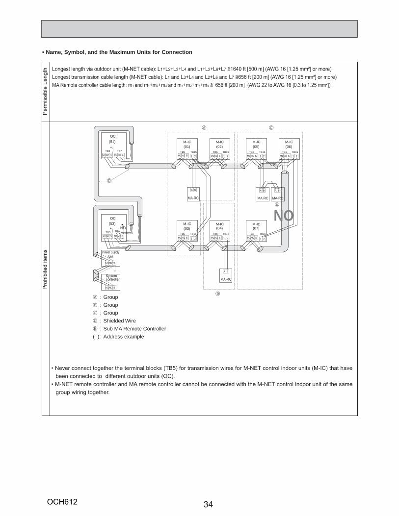
34
• Name, Symbol, and the Maximum Units for ConnectionP
erm
issi
ble
Leng
thP
rohi
bite
d ite
ms
• Never connect together the terminal blocks (TB5) for transmission wires for M-NET control indoor units (M-IC) that have been connected to different outdoor units (OC).
• M-NET remote controller and MA remote controller cannot be connected with the M-NET control indoor unit of the same group wiring together.
A : GroupB : GroupC : GroupD : Shielded WireE : Sub MA Remote Controller( ): Address example
A
B
C
E
M-IC(51)
TB5 TB15 TB15
TB15 TB15
MA-RC
(01)
M-IC
TB5
(03)
M-IC
TB5
(02)
M-IC
TB5
(04)
M-IC(05)
M-IC
TB5
(07)
M-IC(06)
MA-RC
MA-RC
MA-RC
OC
(53)OC
Power SupplyUnit
TB7TB3M1 M2 S M1 M2 S
TB7
M1 M2 SM1 M2 S
TB3
M1 M2 S
M1 M2 S
M1 M2 S M1 M2 S M1 M2 S
M1 M2 S M1 M2 S
A B
A B
A B A B
1 2
1 2 1 2 1 2
1 2TB15TB5
M1 M2 S 1 2TB15TB5
M1 M2 S 1 2
TB15
D
System controller
NO
NO
Longest length via outdoor unit (M-NET cable): L1+L2+L3+L4 and L1+L2+L6+L7 [1640 ft [500 m] (AWG 16 [1.25 mm²] or more)Longest transmission cable length (M-NET cable): L1 and L3+L4 and L2+L6 and L7 [656 ft [200 m] (AWG 16 [1.25 mm²] or more)MA Remote controller cable length: m1 and m1+m2+m3 and m1+m2+m3+m4 [ 656 ft [200 m] (AWG 22 to AWG 16 [0.3 to 1.25 mm²])
OCH612
35
8 TROUBLESHOOTING
8-1. CHECK POINTS FOR TEST RUN8-1-1. Procedures before test run(1) Before a test run, make sure that the following work is completed.
• Installation related : Make sure that the panel of cassette type and electrical wiring are done.Otherwise electrical functions like auto vane will not operate normally.
• Piping related : Perform leakage test of refrigerant and drain piping.Make sure that all joints are perfectly insulated.Check stop valves on both liquid and gas side for full open.
• Electrical wiring related : Check ground wire, transmission cable, remote controller cable, and power supply cable for secure connection.Make sure that all switch settings of address or adjustments for special specification systems are correctly settled.
(2) Safety check : With the insulation tester of 500 V, inspect the insulation resistance.Do not touch the transmission cable and remote controller cable with the tester.The resistance should be over 1.0 M". Do not proceed inspection if the resistance is under 1.0 M".Inspect between the outdoor unit power supply terminal block and ground first, metallic parts like refrigerant pipes or the electrical box next, then inspect all electrical wiring of outdoor unit, indoor unit, and all linked equipment .
(3) Before operation : a) Turn the power supply switch of the outdoor unit to on for compressor protection. For a test run, wait at least 12 hours
from this point.b) Register control systems into remote controller(s). Never touch the ON/OFF switch of the remote controller(s). Refer to “7-2.
Special Function Operation and Settings for M-NET Remote Controller” as for settings. In MA remote controller(s), this registration is unnecessary.
(4) More than 12 hours later from power supply to the outdoor unit, turn all power switch to on for the test run. Perform test run according to the “Operation procedure” table of the bottom of this page. While test running, make test run reports .
8-1-1-1. Test run for M-NET Remote controllerFor the detailed procedure, refer to the remote controller's manuals.
OCH612
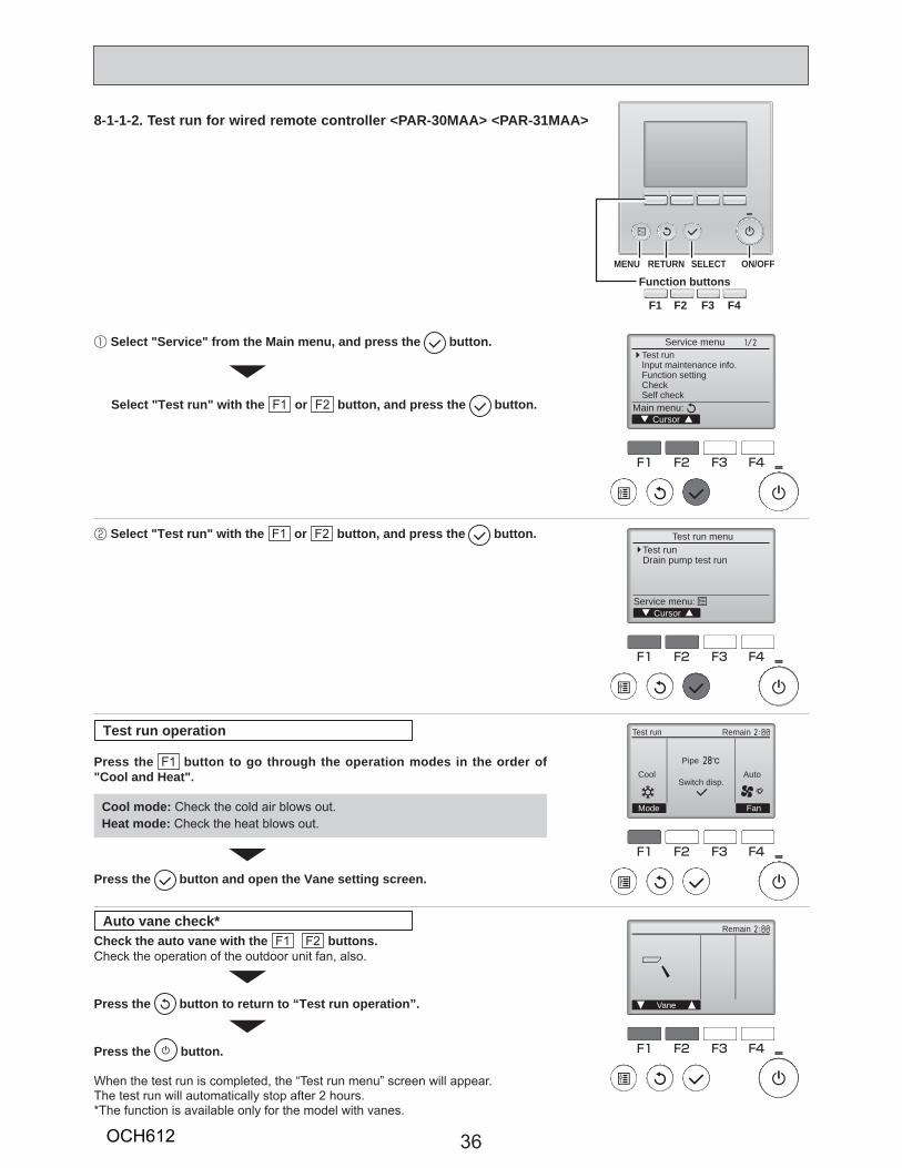
36
F1 F2 F3 F4
unem ecivreS
rosruC:unem niaM
Test runInput maintenance info.Function settingCheckSelf check
F1 F2 F3 F4
Test run menu
CursorService menu:
Test runDrain pump test run
1 Select "Service" from the Main menu, and press the button.
2 Select "Test run" with the F1 or F2 button, and press the button.
Select "Test run" with the F1 or F2 button, and press the button.
F1 F2 F3 F4
CoolPipe
AutoSwitch disp.
Mode Fan
RemainTest run
F1 F2 F3 F4
Remain
Vane
Cool mode: Check the cold air blows out.Heat mode: Check the heat blows out.
Press the F1 button to go through the operation modes in the order of "Cool and Heat".
Check the auto vane with the F1 F2 buttons. Check the operation of the outdoor unit fan, also.
Press the button to return to “Test run operation”.
Press the button.
When the test run is completed, the “Test run menu” screen will appear.The test run will automatically stop after 2 hours.*The function is available only for the model with vanes.
Test run operation
Auto vane check*
Press the button and open the Vane setting screen.
Function buttons
F1 F2 F3 F4
MENU RETURN SELECT ON/OFF
8-1-1-2. Test run for wired remote controller <PAR-30MAA> <PAR-31MAA>
OCH612
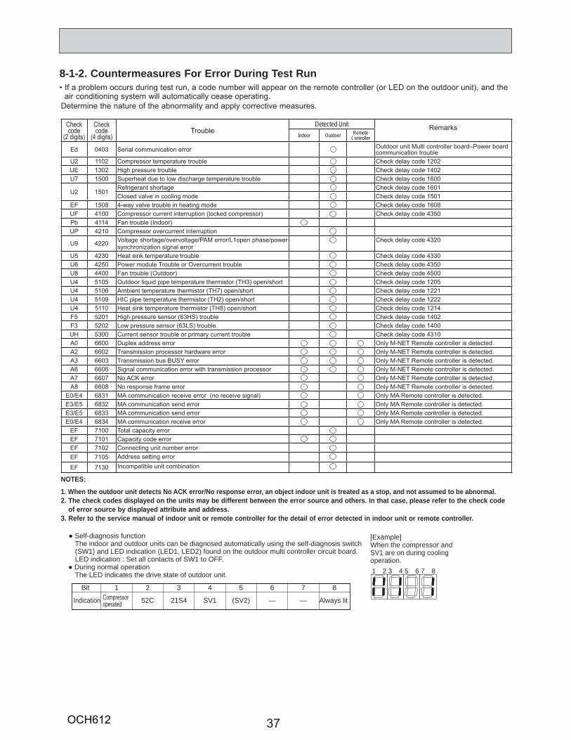
37
8-1-2. Countermeasures For Error During Test Run
1 2 3 4 5 6 7 8
[Example]When the compressor and SV1 are on during cooling operation.
Bit
Indication
1Compressor operated
2
52C
3
21S4
4
SV1
5
(SV2)
6
—
7
—
8
Always lit
Self-diagnosis functionThe indoor and outdoor units can be diagnosed automatically using the self-diagnosis switch(SW1) and LED indication (LED1, LED2) found on the outdoor multi controller circuit board.LED indication : Set all contacts of SW1 to OFF.
During normal operationThe LED indicates the drive state of outdoor unit.
Detected UnitIndoor Outdoor Remote
Controller
3
3U7 1500 1 00
U 15011 011501
1508 1 08U 100 350
11U 10
U9 0 1 3 0
U5 30 330U 50 350U8 00 500U 5105 3 1 05U 510 7 1 1U 5109 1U 5110 8 1 1
5 5 01 3 1 03 5 0 3 1 00
UH 5300 3100 00
03 03 U
07 078 08
0 8313 5 833 5 8330 83
7100710171071057130
NOTES:
1. When the outdoor unit detects No ACK error/No response error, an object indoor unit is treated as a stop, and not assumed to be abnormal.2. The check codes displayed on the units may be different between the error source and others. In that case, please refer to the check code
of error source by displayed attribute and address.3. Refer to the service manual of indoor unit or remote controller for the detail of error detected in indoor unit or remote controller.
OCH612
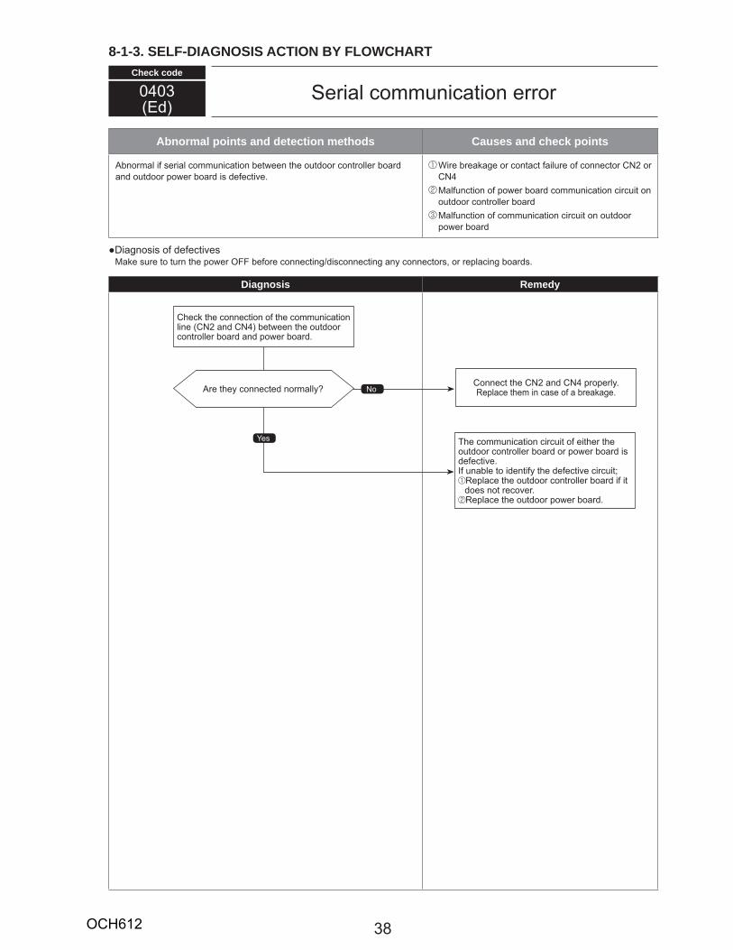
Check code
Abnormal points and detection methods Causes and check points
Diagnosis Remedy
0 03
38
8-1-3. SELF-DIAGNOSIS ACTION BY FLOWCHART
OCH612
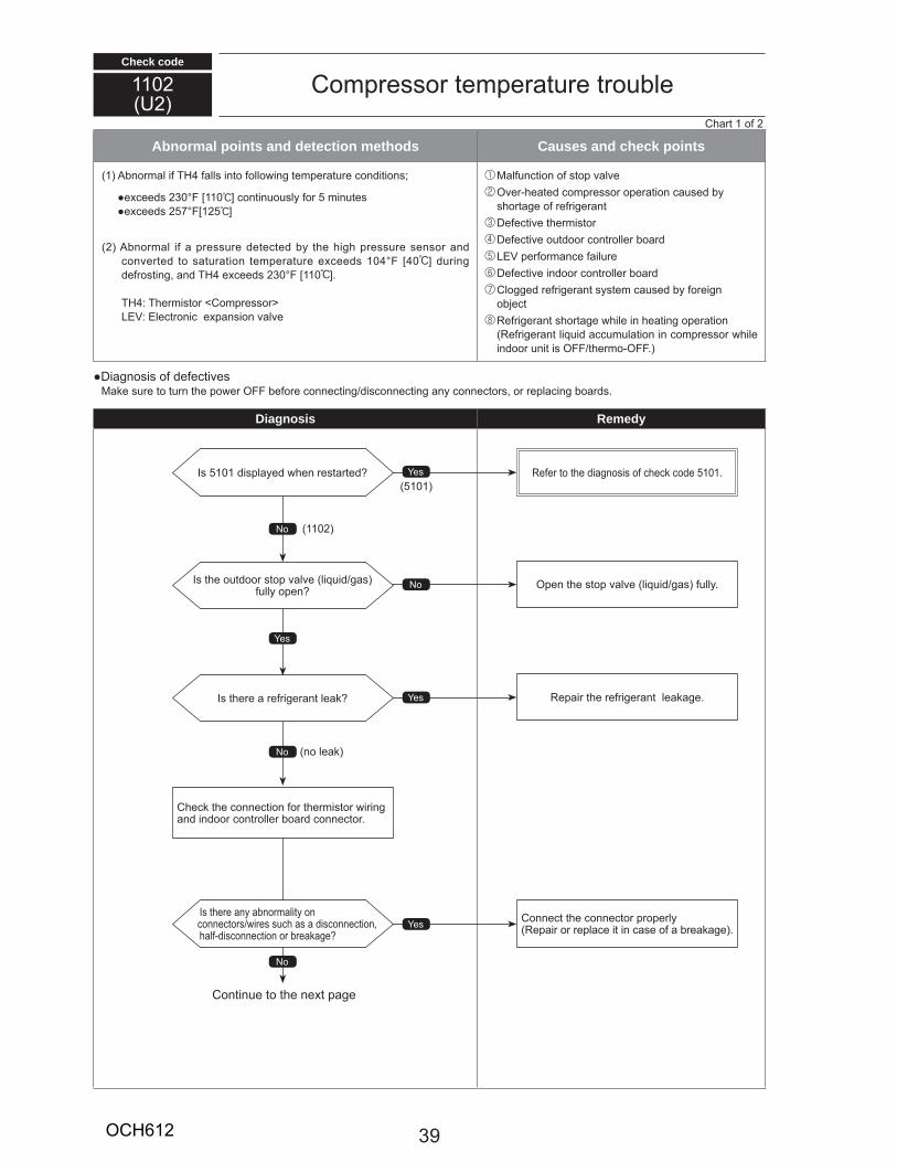
Check code
Abnormal points and detection methods Causes and check points
1 H
30 110 557 1 5 ]
10 0 ]H 30 110 ]
H
Diagnosis Remedy
110U
5101 51015101
110
1
39OCH612
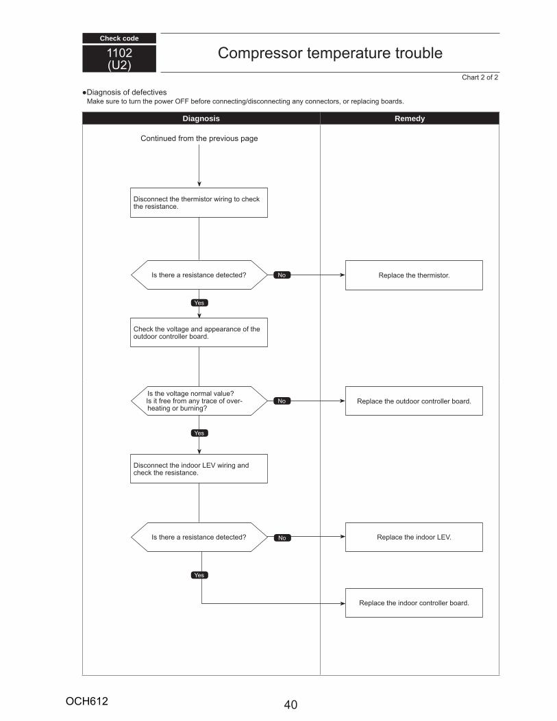
Check code
110U
Diagnosis Remedy
0OCH612
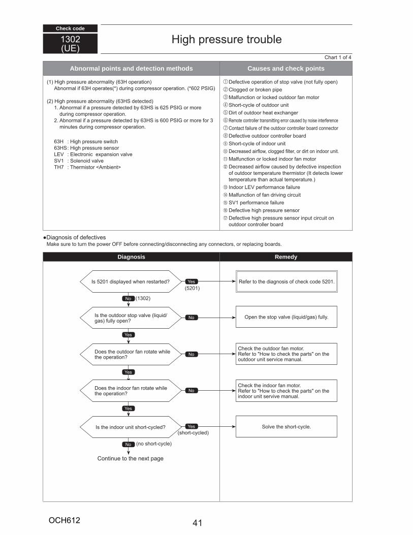
Check code
130U
H
Abnormal points and detection methods Causes and check points
1 H 3H3H 0
H 3H1 3H 5
3H 00 3
3H H3H H
1TH7 T
1
Diagnosis Remedy
1
5 01 5 01
H
H
5 01
130
1OCH612
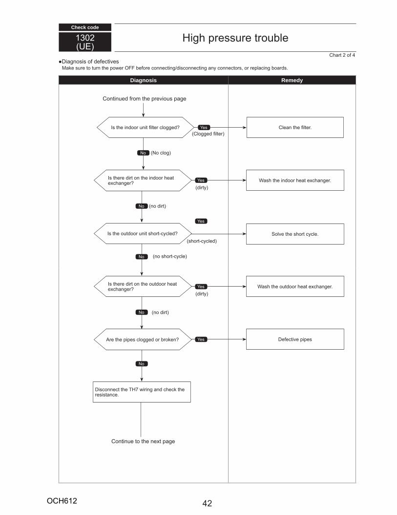
Check code
130U
H
Diagnosis Remedy
TH7
OCH612
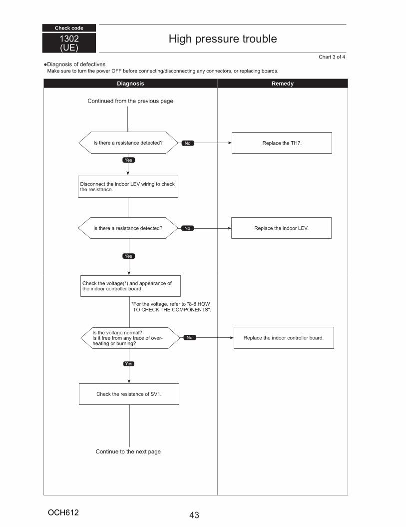
Check code
130U
H
Diagnosis Remedy
1
3
8 8 HT H TH T
TH7
3OCH612
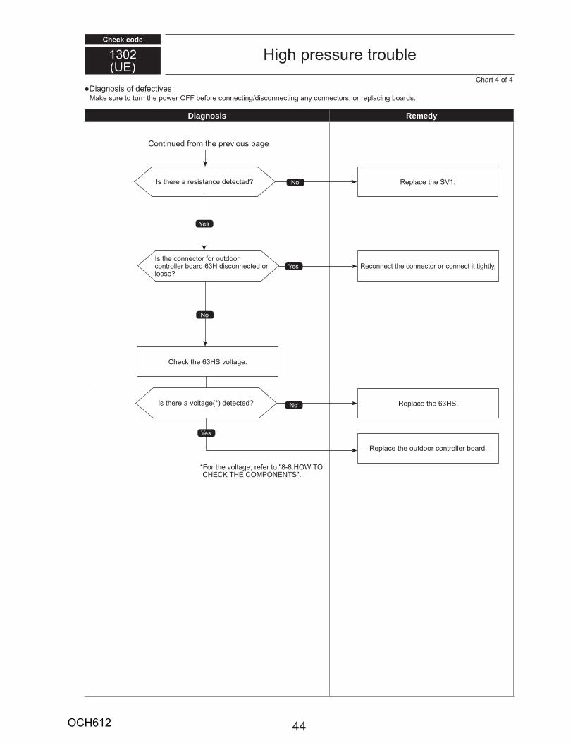
Check code
130U
H
Diagnosis Remedy
8 8 H TH TH T
1
3H
3H
3H
OCH612

Check code
1500U7
Abnormal points and detection methods Causes and check points
7 15 ]5
10
TH T3H H
TH 3H
THTH
Diagnosis Remedy
1
3 0 ] 700 " 50 10 ] 10 "8 0 ] 50 " 8 30 ] 1 0 "
10 0 ] 10 "
TH
TH
TH
5OCH612
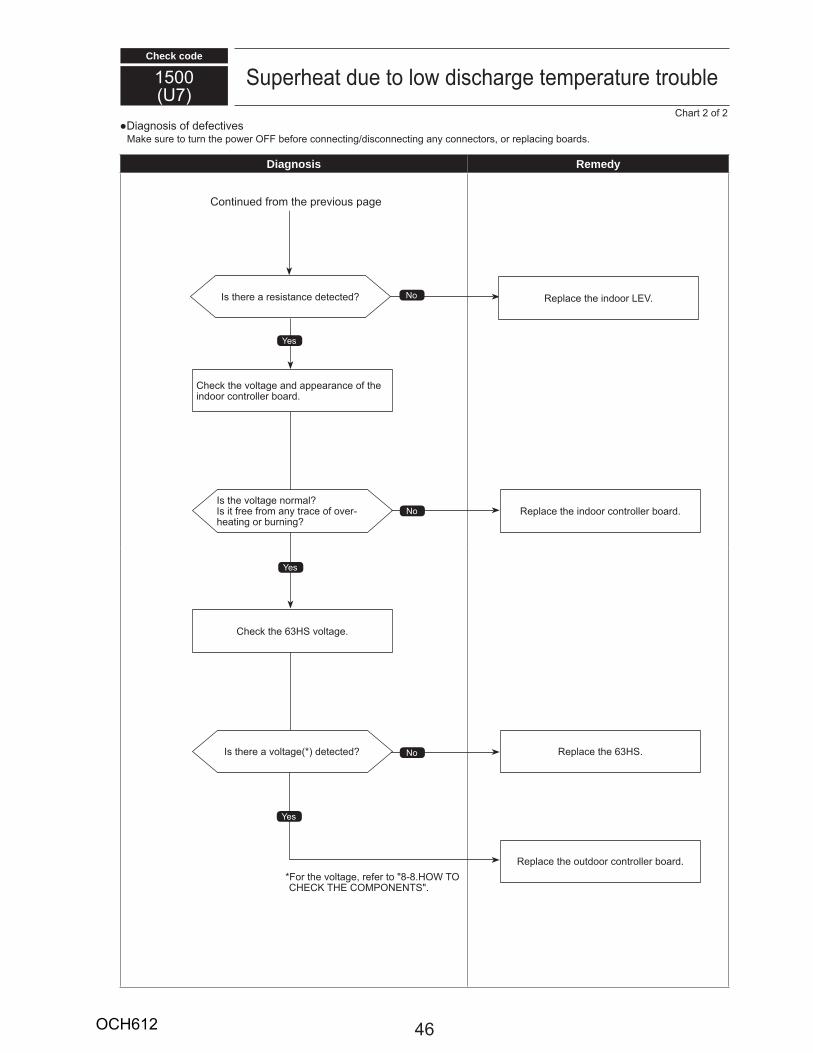
Check code
1500U7
Diagnosis Remedy
8 8 H TH TH T
3H
3H
OCH612
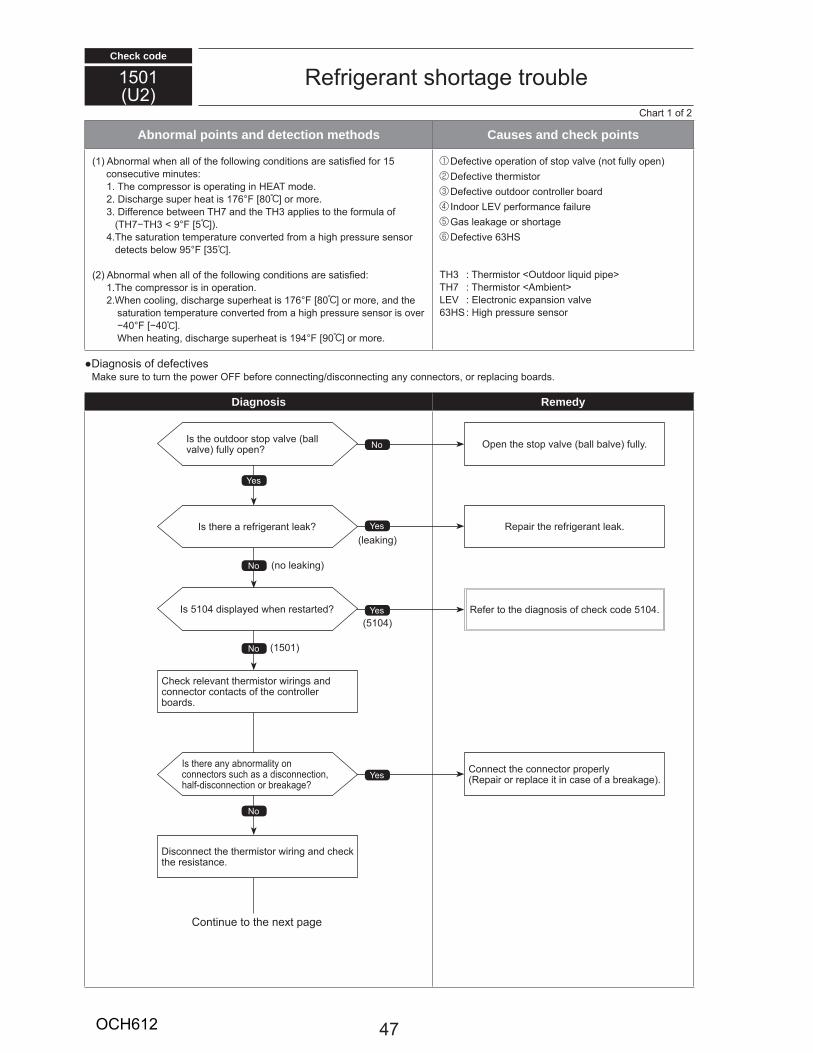
Check code
1501U
Abnormal points and detection methods Causes and check points
1 15
1 T H T17 80 ]
3 TH7 TH3TH7 TH3 9 5 ]
T95 35 ]
1 T17 80 ]
0 0 ]19 90 ]
3H
TH3 TTH7 T
3H H
Diagnosis Remedy
1
510 510510
1501
7OCH612
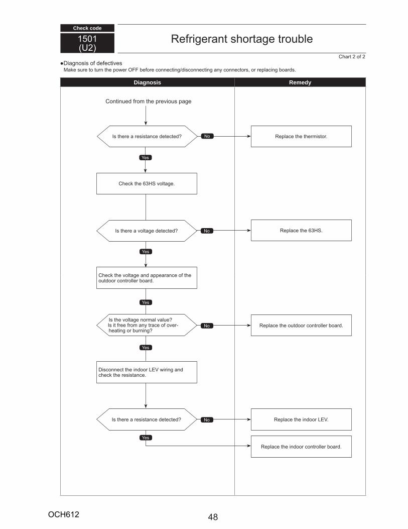
Check code
1501U
Diagnosis Remedy
3H
3H
8OCH612
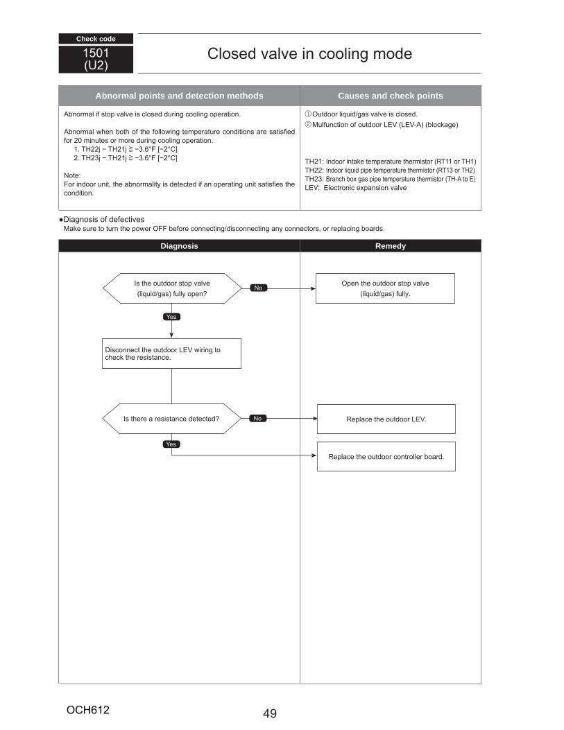
Check code
1501U
Abnormal points and detection methods Causes and check points
01 TH TH 1 ] 3 ]
TH 3 TH 1 ] 3 ] TH 1 T11 TH1TH T13 THTH 3 TH )
Diagnosis Remedy
9OCH612
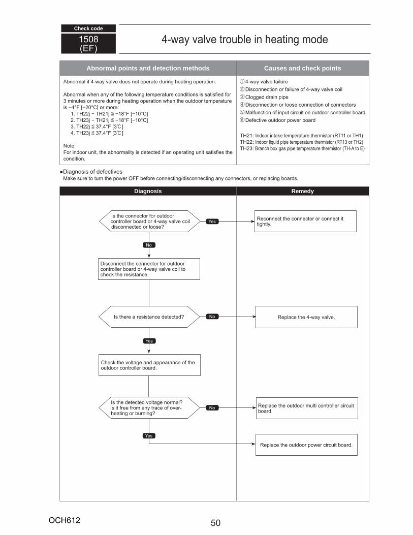
Check code
1508
Abnormal points and detection methods Causes and check points
30 ]
1 TH TH 1 [ 18 10 ]TH 3 TH 1 [ 18 10 ]
3 TH [ 37 3:]TH 3 [ 37 3:] TH 1 T11 TH1
TH T13 THTH 3 TH
Diagnosis Remedy
50OCH612
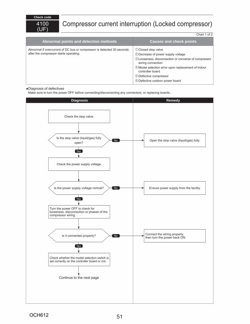
Check code
Abnormal points and detection methods Causes and check points
30
Diagnosis Remedy
100U
1
T
51OCH612
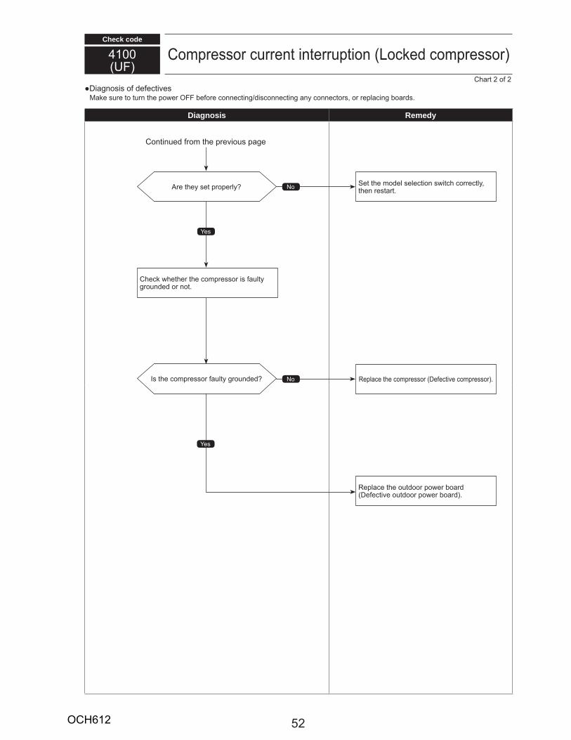
Check code
100U
Diagnosis Remedy
5OCH612
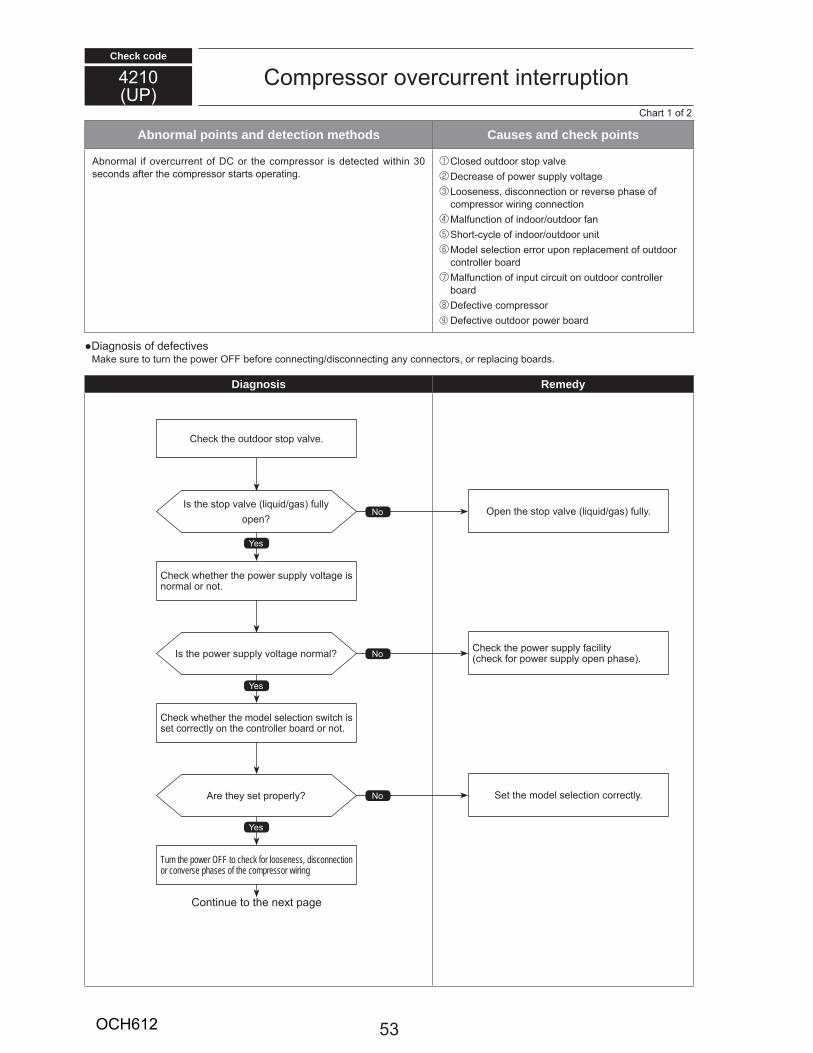
Check code
Abnormal points and detection methods Causes and check points
30
Diagnosis Remedy
10U
1
Turn the power OFF to check for looseness, disconnection or converse phases of the compressor wiring
53OCH612
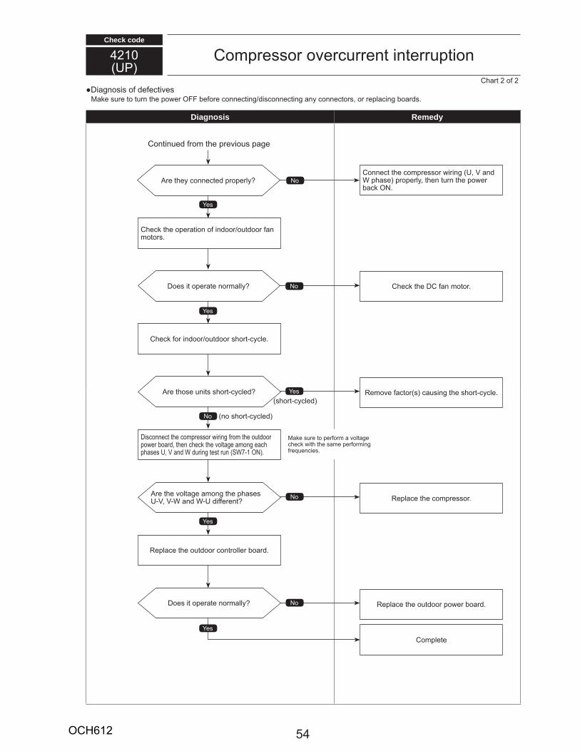
Check code
10U
Diagnosis Remedy
U
U U
U 7 1
5OCH612

Check code
0U9
1
Abnormal points and detection methods Causes and check points
0000
310 300 H
0 1
1 T 0 HT
2
55
5
5
0
Diagnosis RemedyT
3
7 8
350
55
T1
T1
ONOFF
1 2 3 4 5 6 7 8
SW1 Setting Display on LED1,21 2 3 4 5 6 7 8
3
78
3
7 U8
U 1
55OCH612
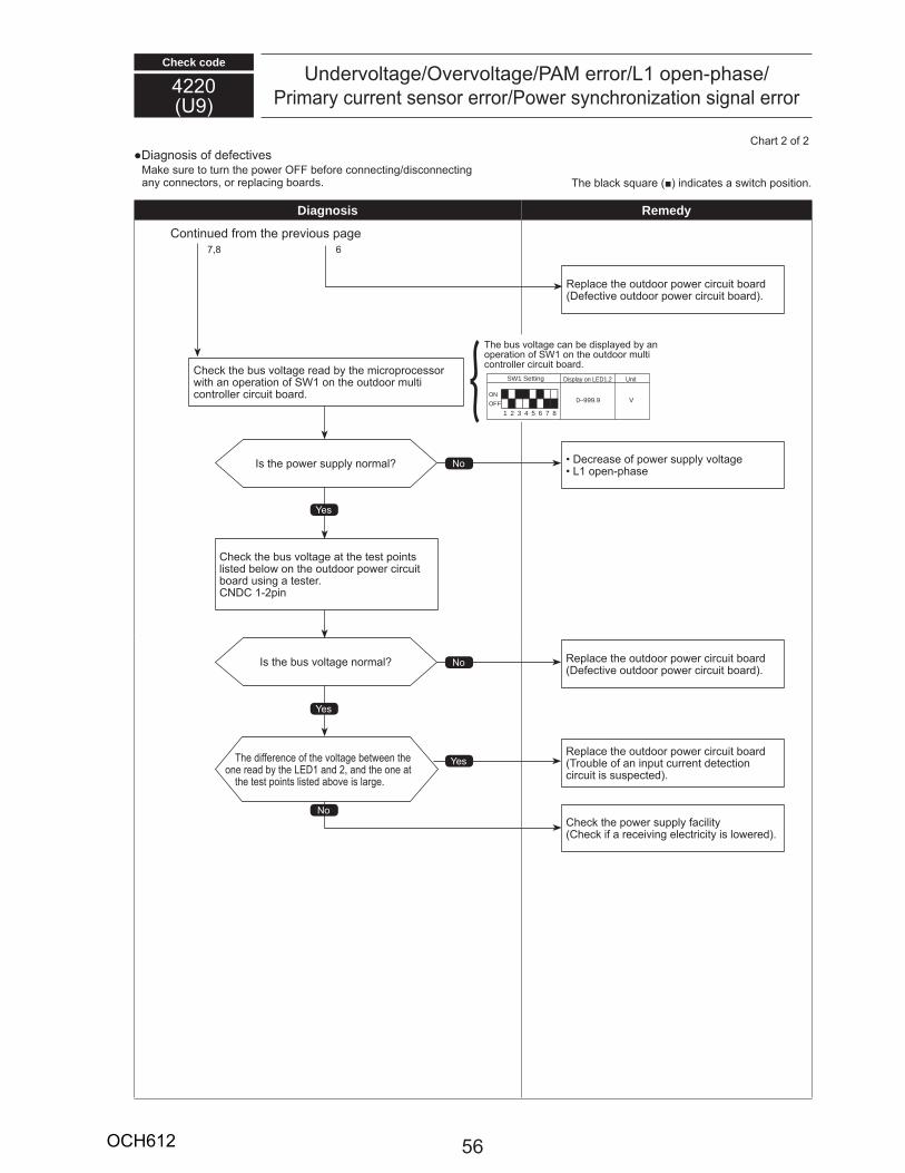
Check code
0U9
U 1
Diagnosis Remedy
T
7 8
T1
T1
1
T
1
1
ONOFF
1 2 3 4 5 6 7 8
SW1 Setting Display on LED1,2
0–999.9
Unit
V
5OCH612
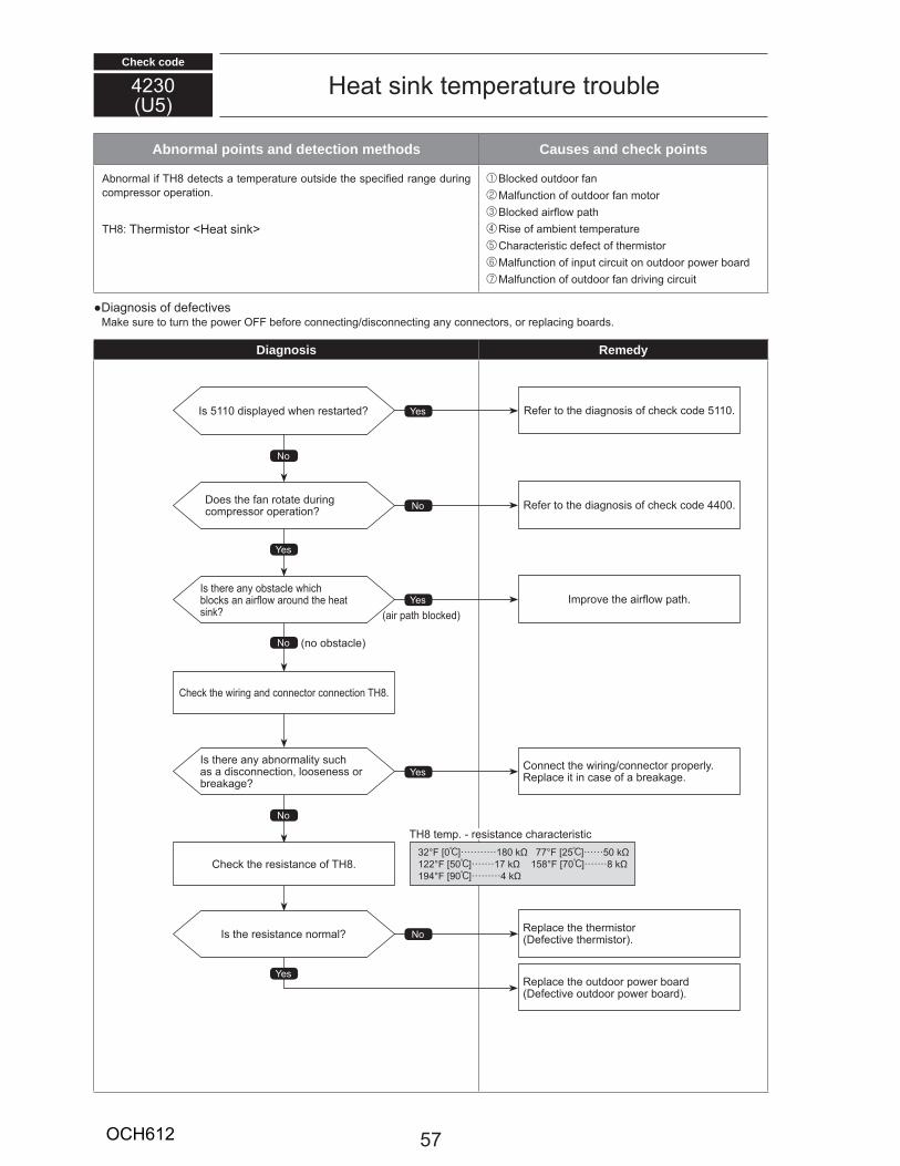
Check code
Abnormal points and detection methods Causes and check points
TH8
TH8 T H
Diagnosis Remedy
5110
30U5
H
3 0 ] 180 77 5 ] 501 50 ] 17 158 70 ] 819 90 ]
5110 5110
00
TH8
TH8
TH8
57OCH612
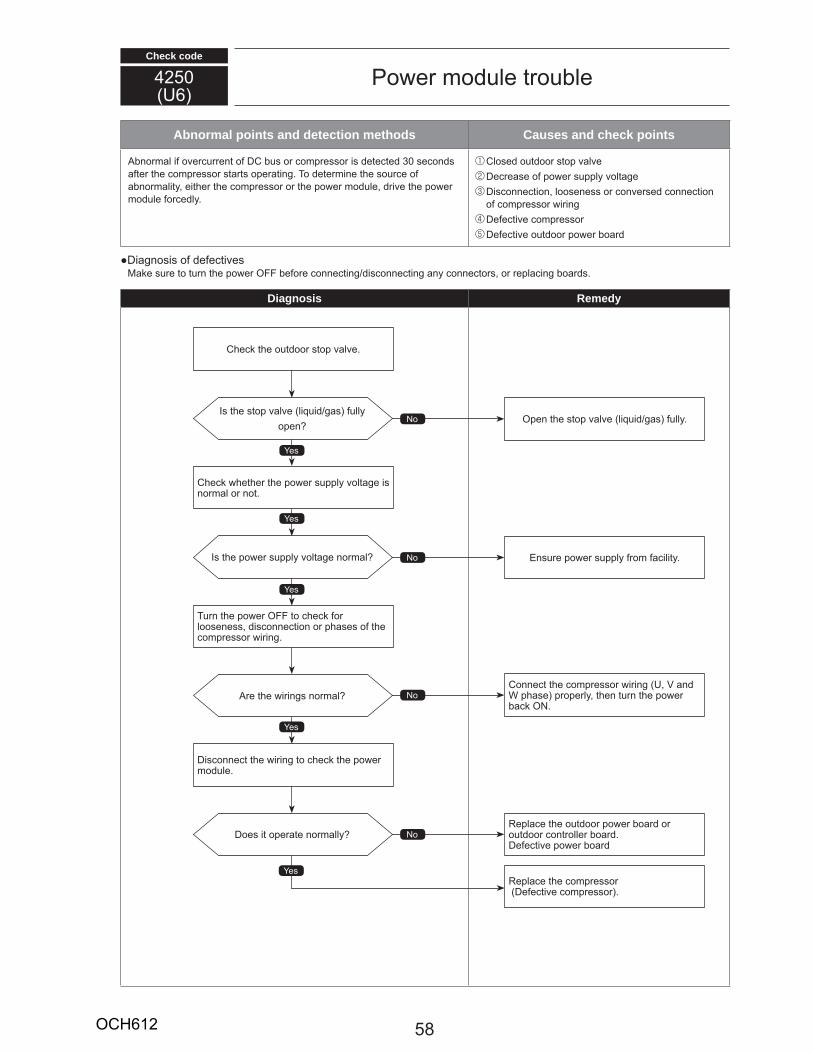
Check code
Abnormal points and detection methods Causes and check points
30T
Diagnosis Remedy
50U
U
T
58OCH612

Check code
Abnormal points and detection methods Causes and check points
Diagnosis Remedy
00U8
8 7
1
1
TV 80 380 V 1VCC 15 V C 5
59OCH612
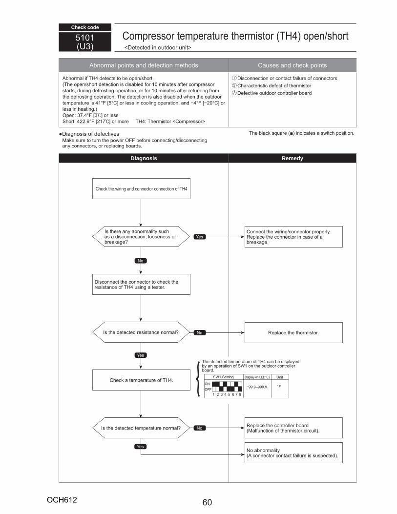
Check code
C
THT 10
10T
1 5 C] 0 C]
37 3 ]17 ] TH T C
C
Diagnosis Remedy
5101U3
C TH
T
C
C TH
TH
C TH
T TH1
1 1 U
99 9 999 9
1 5 7 83
0OCH612
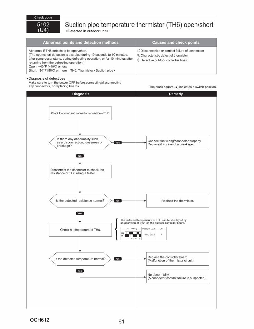
Check code
Abnormal points and detection methods Causes and check points
THT 10 10
10
0 0 ]19 90 ] TH T
C
Diagnosis Remedy
510U
TH
T
C
C TH
TH
C THONOFF
1 2 3 4 5 6 7 8
SW1 Setting Display on LED1,2 Unit
99.9–999.9 ºF
T e ete te te pe at e o TH6 an e isplaye y an ope ation o SW1 on t e o t oo ont olle oa .
61OCH612
Check code
Abnormal points and detection methods Causes and check points
no al i TH3 ete ts to e open s o t.T e open s o t ete tion is isa le ing 10 se on s to 10 in tes.
a te o p esso sta ts, ing e osting ope ation, o o 10 in tes a te et ning o t e e osting ope ation.
Open 40 F 40 ] o lessS o t 194 F 90 ] o o e TH3 T e isto O t oo li i pipe
Dis onne tion o onta t ail e o onne to s C a a te isti e e t o t e isto De e ti e o t oo ont olle oa
Diagnosis o e e ti esa e s e to t n t e po e OFF e o e onne ting is onne ting
any onne to s, o epla ing oa s.
Diagnosis Remedy
5105U4
O t oo li i pipe te pe at e t e isto TH3 open s o t
T e la s a e in i ates a s it position.
SW1 Setting
ONOFF
Display on LED1, 2 Unit
99.9–999.9
41 2 5 6 7 83
F
No
es
es
es
No
No
s t e e any a no ality sas a is onne tion, looseness o
ea age
s t e ete te esistan e no al
s t e ete te te pe at e no al
Conne t t e i ing onne to p ope lyepla e it in ase o a ea age.
epla e t e t e isto .
epla e t e ont olle oaal n tion o t e isto i it .
No a no ality onne to onta t ail e is s spe te .
C e t e i ing an onne to onne tion o TH3.
Dis onne t t e onne to to e t e esistan e o TH3 sing a teste .
C e a te pe at e o TH3.
T e ete te te pe at e o TH3 an e isplaye y an ope ation o SW1 on t e o t oo ont olle oa .
62OCH612
Check code
5106U4
ient te pe at e t e isto TH7 open s o t
Abnormal points and detection methods Causes and check points
no al i TH7 ete ts to e open s o tOpen 40 F 40:] o lessS o t 194 F 90:] o o e TH7 T e isto ient
Dis onne tion o onta t ail e o onne to s C a a te isti e e t o t e isto De e ti e o t oo ont olle oa
Diagnosis o e e ti esa e s e to t n t e po e OFF e o e onne ting is onne ting
any onne to s, o epla ing oa s.
Diagnosis RemedyT e la s a e in i ates a s it position.
SW1 Setting
ONOFF
Display on LED1, 2 Unit
99.9–999.9
41 2 5 6 7 83
F
No
es
es
es
No
No
s t e e any a no ality sas a is onne tion, looseness o
ea age
s t e ete te esistan e no al
s t e ete te te pe at e no al
Conne t t e i ing onne to p ope ly.epla e it in ase o a ea age.
epla e t e t e isto .
epla e t e ont olle oaal n tion o t e isto i it .
No a no ality onne to onta t ail e is s spe te .
C e t e i ing an onne to onne tion o TH7.
Dis onne t t e onne to to e t e esistan e o TH7 sing a teste .
C e a te pe at e o TH7.
T e ete te te pe at e o t e isto TH7 an e isplaye y an ope ation o SW1 on t e
o t oo ont olle oa .T e ete te te pe at e o TH7 an e isplaye y an ope ation o SW1 on t e o t oo ont olle oa .
63OCH612

Check code
5109U4
H C pipe te pe at e t e isto TH2 open s o t
Abnormal points and detection methods Causes and check points
no al i TH2 ete ts to e open s o t.Open 40 F 40:] o lessS o t 194 F 90:] o o e TH2 T e isto H C pipe
Dis onne tion o onta t ail e o onne to s C a a te isti e e t o t e isto De e ti e o t oo ont olle oa
Diagnosis o e e ti esa e s e to t n t e po e OFF e o e onne ting is onne ting
any onne to s, o epla ing oa s.
Diagnosis RemedyT e la s a e in i ates a s it position.
No
es
es
es
No
No
s t e e any a no ality sas a is onne tion, looseness o
ea age
s t e ete te esistan e no al
s t e ete te te pe at e no al
Conne t t e i ing onne to p ope ly.epla e it in ase o a ea age.
epla e t e t e isto .
epla e t e ont olle oaal n tion o t e isto i it .
No a no ality onne to onta t ail e is s spe te .
C e t e i ing an onne to onne tion o TH2.
Dis onne t t e onne to to e t e esistan e o TH2 sing a teste .
C e a te pe at e o TH2.ONOFF
1 2 3 4 5 6 7 8
SW1 Setting Display on LED1,2 Unit
99.9–999.9 ºF
T e ete te te pe at e o TH2 an e isplaye y an ope ation o SW1 on t e o t oo ont olle oa .
64OCH612
Check code
5110U4
Heat sin te pe at e t e isto TH8 open s o t
Abnormal points and detection methods Causes and check points
no al i TH8 ete ts to e open s o t. Open 31.2 F 35.1 ] o less
S o t 338.5 F 170.3 ] o o e
TH8 T e isto Heat sin
Dis onne tion o onta t ail e o onne to s C a a te isti e e t o t e isto De e ti e o t oo ont olle oa
Diagnosis o e e ti esa e s e to t n t e po e OFF e o e onne ting is onne ting
any onne to s, o epla ing oa s.
Diagnosis Remedy
o t oo
T e la s a e in i ates a s it position.
SW1 Setting
ONOFF
Display on LED1, 2 Unit
41 2 5 6 7 83F99.9–999.9
No
es
es
es
No
No
es
No
s t e e any a no ality sas a is onne tion, looseness o
ea age
s t e ete te esistan e no al
s t e ete te te pe at e no al
Conne t t e i ing onne to p ope ly.epla e it in ase o a ea age.
epla e t e t e isto .
epla e t e o t oo ont olle oaal n tion o t e isto i it .
No a no ality onne to onta t ail e is s spe te .
C e t e i ing an onne to onne tion o TH8.
Dis onne t t e onne to to e t e esistan e o TH8 sing a teste .
C e a te pe at e o TH8.
T e ete te te pe at e o t e isto TH8 an e isplaye y an ope ation o SW1 on t e
o t oo ont olle oa .T e ete te te pe at e o TH8 an e isplaye y an ope ation o SW1 on t e o t oo ont olle oa .
s it a o el it inte nal t e isto
65OCH612
Check code
5201F5
Hig p ess e senso 63HS t o le
Abnormal points and detection methods Causes and check points
W en t e ete te p ess e in t e ig p ess e senso is 14 S o less ing ope ation, t e o p esso stops ope ation an ente s into an anti esta t o e o 3 in tes. W en t e ete te p ess e is 14 S o less i e iately e o e esta ting, t e o p esso alls into an a no al stop it a e o e 5201 .
Fo 3 in tes a te o p esso esta ting, ing e osting ope ation, an o 3 in tes a te et ning o e osting ope ation, a o e
entione sy pto s a e not ete ine as a no al.
De e ti e ig p ess e senso De ease o inte nal p ess e a se y gas lea age Dis onne tion o onta t ail e o onne to al n tion o inp t i it on o t oo ont olle
oa
Diagnosis o e e ti esa e s e to t n t e po e OFF e o e onne ting is onne ting
any onne to s, o epla ing oa s.
Diagnosis Remedy
T e la s a e in i ates a s it position.
63HS Hig p ess e senso
SW1 Setting
ONOFF
Display on LED1, 2 Unit
99.9–999.9 S
41 2 5 6 7 83
No
es
es
No
No
s t e e any a no ality sas a is onne tion, looseness o
ea age
s t e ete te inte nal p ess e no al
s t e ete te p ess e no al
Conne t t e i ing onne to p ope ly.epla e it in ase o a ea age.
C e t e e ige ant i it, an e ll e ige ant a te epai ing t e lea age.
epla e t e 63HS.
epla e t e o t oo ont olle oa .
C e t e i ing an onne to onne tion.
C e an inte nal p ess e o t e e ige ant i it.
C e t e ete te p ess e in 63HS , t en o pa e it it t e inte nal p ess e.
T e ete te p ess e in 63HS an e isplaye y an ope ation o SW1 on t e o t oo ont olle oa .
Fo t e p ess e, e e to 8 8.HOW TO CHEC THE CO ONENTS .
66OCH612
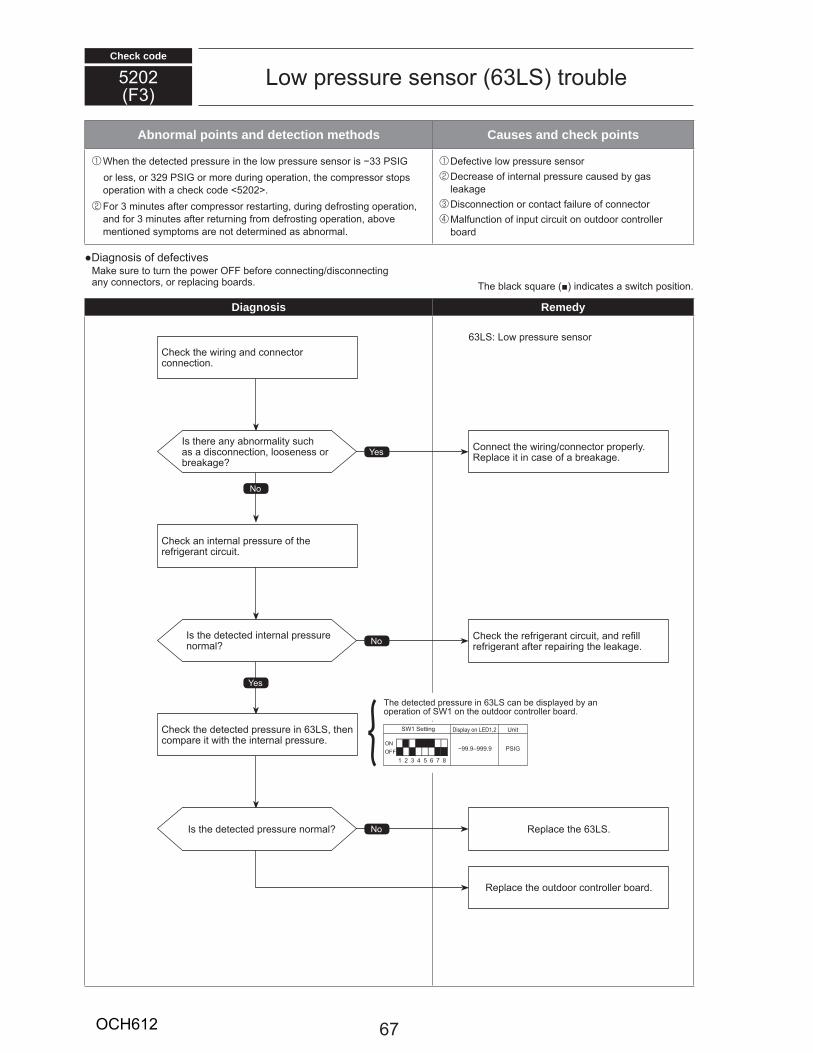
Check code
5202F3
Lo p ess e senso 63LS t o le
Abnormal points and detection methods Causes and check points
W en t e ete te p ess e in t e lo p ess e senso is 33 S o less, o 329 S o o e ing ope ation, t e o p esso stops
ope ation it a e o e 5202 . Fo 3 in tes a te o p esso esta ting, ing e osting ope ation, an o 3 in tes a te et ning o e osting ope ation, a o e
entione sy pto s a e not ete ine as a no al.
De e ti e lo p ess e senso De ease o inte nal p ess e a se y gas lea age Dis onne tion o onta t ail e o onne to al n tion o inp t i it on o t oo ont olle
oa
Diagnosis o e e ti esa e s e to t n t e po e OFF e o e onne ting is onne ting
any onne to s, o epla ing oa s.
Diagnosis Remedy
T e la s a e in i ates a s it position.
63LS Lo p ess e senso
No
es
es
No
No
s t e e any a no ality sas a is onne tion, looseness o
ea age
s t e ete te inte nal p ess e no al
s t e ete te p ess e no al
Conne t t e i ing onne to p ope ly.epla e it in ase o a ea age.
C e t e e ige ant i it, an e ll e ige ant a te epai ing t e lea age.
epla e t e 63LS.
epla e t e o t oo ont olle oa .
C e t e i ing an onne to onne tion.
C e an inte nal p ess e o t e e ige ant i it.
C e t e ete te p ess e in 63LS, t en o pa e it it t e inte nal p ess e. ON
OFF1 2 3 4 5 6 7 8
SW1 Setting Display on LED1,2 Unit
99.9–999.9 PSIG
T e ete te p ess e in 63LS an e isplaye y an ope ation o SW1 on t e o t oo ont olle oa .
67OCH612
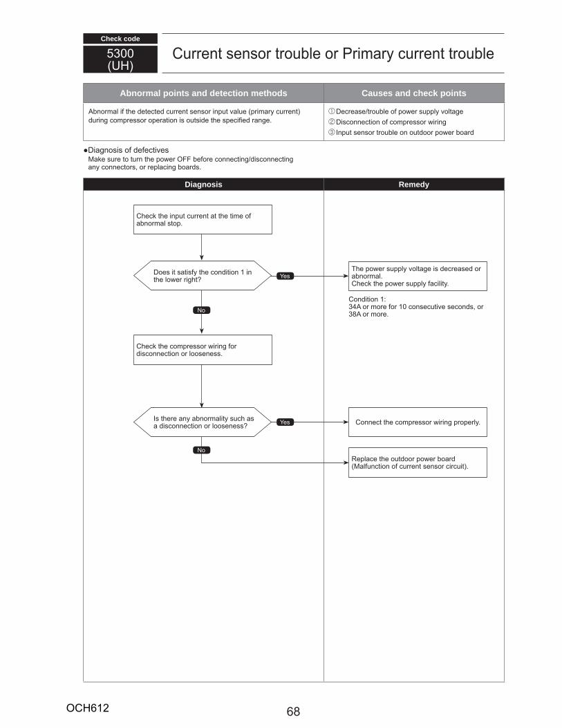
Check code
5300UH
C ent senso t o le o P i a y ent t o le
Abnormal points and detection methods Causes and check points
no al i t e ete te ent senso inp t al e p i a y ent ing o p esso ope ation is o tsi e t e spe i e ange.
De ease t o le o po e s pply oltage Dis onne tion o o p esso i ing Inp t senso t o le on o t oo po e oa
Diagnosis o e e ti esa e s e to t n t e po e OFF e o e onne ting is onne ting
any onne to s, o epla ing oa s.
Diagnosis Remedy
No
No
es
es
Does it satis y t e on ition 1 in t e lo e ig t
Is t e e any a no ality s as a is onne tion o looseness
T e po e s pply oltage is e ease o a no al.C e t e po e s pply a ility.
Conne t t e o p esso i ing p ope ly.
epla e t e o t oo po e oaal n tion o ent senso i it .
C e t e inp t ent at t e ti e o a no al stop.
C e t e o p esso i ing o is onne tion o looseness.
Con ition 134 o o e o 10 onse ti e se on s, o 38 o o e.
68OCH612
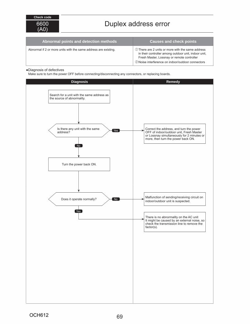
Check code
Abnormal points and detection methods Causes and check points
no al i 2 o o e nits it t e sa e a ess a e e isting. T e e a e 2 nits o o e it t e sa e a ess in t ei ont olle a ong o t oo nit, in oo nit, F es aste , Lossnay o e ote ont olle Noise inte e en e on in oo o t oo onne to s
Diagnosis o e e ti esa e s e to t n t e po e OFF e o e onne ting is onne ting any onne to s, o epla ing oa s.
Diagnosis Remedy
66000
D ple a ess e o
No
es
es
No
Is t e e any nit it t e sa e a ess
Does it ope ate no ally
Co e t t e a ess, an t n t e po e OFF o in oo o t oo nit, F es aste o Lossnay si ltaneo sly o 2 in tes o
o e, t en t n t e po e a ON.
al n tion o sen ing e ei ing i it on in oo o t oo nit is s spe te .
T e e is no a no ality on t e C nitIt ig t e a se y an e te nal noise, so
e t e t ans ission line to e o e t e a to s .
Sea o a nit it t e sa e a ess as t e so e o a no ality.
T n t e po e a ON.
69OCH612
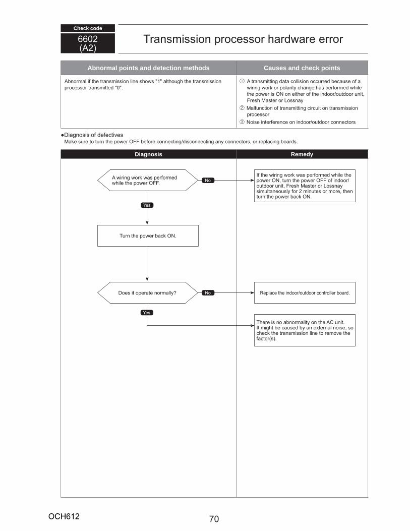
Check code
Abnormal points and detection methods Causes and check points
no al i t e t ans ission line s o s 1 alt o g t e t ans ission p o esso t ans itte 0 .
t ans itting ata ollision o e e a se o a i ing o o pola ity ange as pe o e ile
t e po e is ON on eit e o t e in oo o t oo nit, F es aste o Lossnay
al n tion o t ans itting i it on t ans ission p o esso
Noise inte e en e on in oo o t oo onne to s
Diagnosis o e e ti esa e s e to t n t e po e OFF e o e onne ting is onne ting any onne to s, o epla ing oa s.
Diagnosis Remedy
66022
T ans ission p o esso a a e e o
es
es
No
No
i ing o as pe o e ile t e po e OFF.
Does it ope ate no ally
I t e i ing o as pe o e ile t e po e ON, t n t e po e OFF o in ooo t oo nit, F es aste o Lossnay si ltaneo sly o 2 in tes o o e, t en t n t e po e a ON.
epla e t e in oo o t oo ont olle oa .
T e e is no a no ality on t e C nit.It ig t e a se y an e te nal noise, so
e t e t ans ission line to e o e t e a to s .
T n t e po e a ON.
70OCH612
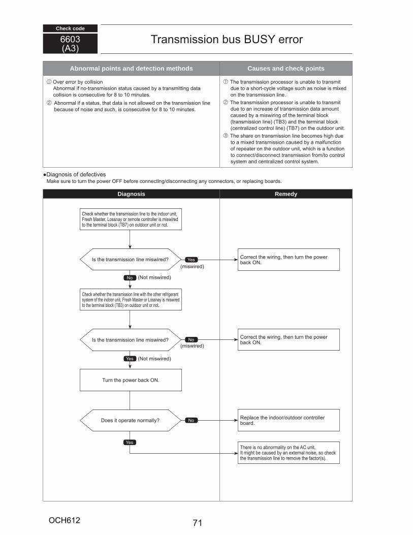
Check code
Abnormal points and detection methods Causes and check points
O e e o y ollisionno al i no t ans ission stat s a se y a t ans itting ata
ollision is onse ti e o 8 to 10 in tes. no al i a stat s, t at ata is not allo e on t e t ans ission line
e a se o noise an s , is onse ti e o 8 to 10 in tes.
T e t ans ission p o esso is na le to t ans it e to a s o t y le oltage s as noise is i e
on t e t ans ission line. T e t ans ission p o esso is na le to t ans it
e to an in ease o t ans ission ata a o nt a se y a is i ing o t e te inal lo t ans ission line T 3 an t e te inal lo ent ali e ont ol line T 7 on t e o t oo nit.
T e s a e on t ans ission line e o es ig e to a i e t ans ission a se y a al n tion o epeate on t e o t oo nit, i is a n tion to onne t is onne t t ans ission o to ont ol syste an ent ali e ont ol syste .
Diagnosis o e e ti esa e s e to t n t e po e OFF e o e onne ting is onne ting any onne to s, o epla ing oa s.
Diagnosis Remedy
66033
T ans ission s US e o
No
es
es
es
No
No
Is t e t ans ission line is i e
Is t e t ans ission line is i e
Does it ope ate no ally
Co e t t e i ing, t en t n t e po e a ON.
Co e t t e i ing, t en t n t e po e a ON.
epla e t e in oo o t oo ont olle oa .
T e e is no a no ality on t e C nit.It ig t e a se y an e te nal noise, so e t e t ans ission line to e o e t e a to s .
C e et e t e t ans ission line to t e in oo nit, F es aste , Lossnay o e ote ont olle is is i e to t e te inal lo T 7 on o t oo nit o not.
C e et e t e t ans ission line it t e ot e e ige ant syste o t e in oo nit, F es aste o Lossnay is is i e to t e te inal lo T 3 on o t oo nit o not.
T n t e po e a ON.
is i e
is i e
Not is i e
Not is i e
71OCH612

Check code
Abnormal points and detection methods Causes and check points
no al i t e ata o nit t ans ission p o esso e e not no ally t ans itte .
no al i t e a ess t ans ission o t e nit p o esso as not no ally t ans itte .
i ental ist an e s as noise o lig tning s ge Ha a e al n tion o t ans ission p o esso
Diagnosis o e e ti esa e s e to t n t e po e OFF e o e onne ting is onne ting any onne to s, o epla ing oa s.
Diagnosis Remedy
66066
Signal o ni ation e o it t ans ission p o esso
es
NoDoes it ope ate no ally epla e t e ont olleDe e t o e o so e ont olle .
T e e is no a no ality on t e C nit.It ig t e a se y an e te nal noise, so e t e t ans ission line to e o e t e a to s .
T n t e po e OFF o in oo o t oo nit, F es aste , Lossnay an e ote ont olle si ltaneo sly
o 2 in tes o o e, t en t n t e po e a ON.
72OCH612
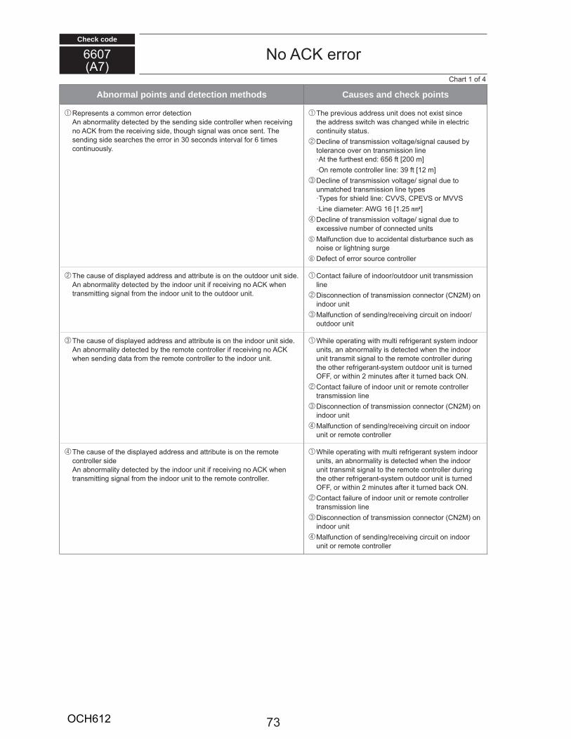
Check code
Abnormal points and detection methods Causes and check points
ep esents a o on e o ete tionn a no ality ete te y t e sen ing si e ont olle en e ei ing
no C o t e e ei ing si e, t o g signal as on e sent. T e sen ing si e sea es t e e o in 30 se on s inte al o 6 ti es ontin o sly.
T e p e io s a ess nit oes not e ist sin e t e a ess s it as ange ile in ele t i ontin ity stat s.
De line o t ans ission oltage signal a se y tole an e o e on t ans ission line
t t e t est en 656 t 200 ]On e ote ont olle line 39 t 12 ]
De line o t ans ission oltage signal e to n at e t ans ission line typesTypes o s iel line CVVS, CPEVS o VVSLine ia ete WG 16 1.25 E]
De line o t ans ission oltage signal e to e essi e n e o onne te nits al n tion e to a i ental ist an e s as noise o lig tning s ge De e t o e o so e ont olle
T e a se o isplaye a ess an att i te is on t e o t oo nit si e.n a no ality ete te y t e in oo nit i e ei ing no C en
t ans itting signal o t e in oo nit to t e o t oo nit.
Conta t ail e o in oo o t oo nit t ans ission line Dis onne tion o t ans ission onne to CN2 on in oo nit al n tion o sen ing e ei ing i it on in ooo t oo nit
T e a se o isplaye a ess an att i te is on t e in oo nit si e.n a no ality ete te y t e e ote ont olle i e ei ing no C
en sen ing ata o t e e ote ont olle to t e in oo nit.
W ile ope ating it lti e ige ant syste in oo nits, an a no ality is ete te en t e in oo nit t ans it signal to t e e ote ont olle ing
t e ot e e ige ant syste o t oo nit is t ne OFF, o it in 2 in tes a te it t ne a ON. Conta t ail e o in oo nit o e ote ont olle t ans ission line Dis onne tion o t ans ission onne to CN2 on in oo nit al n tion o sen ing e ei ing i it on in oo
nit o e ote ont olle
T e a se o t e isplaye a ess an att i te is on t e e ote ont olle si en a no ality ete te y t e in oo nit i e ei ing no C en
t ans itting signal o t e in oo nit to t e e ote ont olle .
W ile ope ating it lti e ige ant syste in oo nits, an a no ality is ete te en t e in oo nit t ans it signal to t e e ote ont olle ing
t e ot e e ige ant syste o t oo nit is t ne OFF, o it in 2 in tes a te it t ne a ON. Conta t ail e o in oo nit o e ote ont olle t ans ission line Dis onne tion o t ans ission onne to CN2 on in oo nit al n tion o sen ing e ei ing i it on in oo
nit o e ote ont olle
66077
No C e oC a t 1 o 4
73OCH612
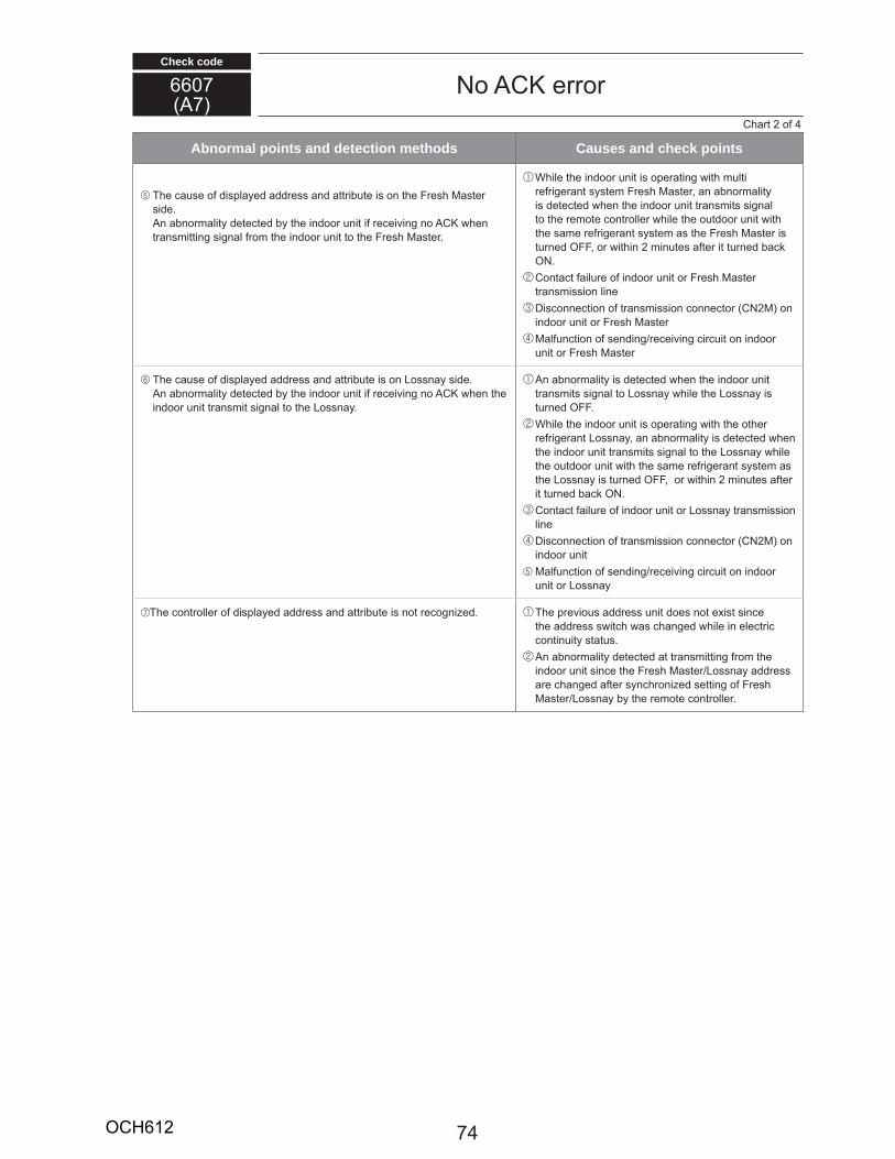
Check code
66077
No C e o
Abnormal points and detection methods Causes and check points
T e a se o isplaye a ess an att i te is on t e F es aste si e.
n a no ality ete te y t e in oo nit i e ei ing no C en t ans itting signal o t e in oo nit to t e F es aste .
W ile t e in oo nit is ope ating it lti e ige ant syste F es aste , an a no ality
is ete te en t e in oo nit t ans its signal to t e e ote ont olle ile t e o t oo nit it t e sa e e ige ant syste as t e F es aste is t ne OFF, o it in 2 in tes a te it t ne a ON. Conta t ail e o in oo nit o F es aste t ans ission line Dis onne tion o t ans ission onne to CN2 on in oo nit o F es aste al n tion o sen ing e ei ing i it on in oo
nit o F es aste
T e a se o isplaye a ess an att i te is on Lossnay si e.n a no ality ete te y t e in oo nit i e ei ing no C en t e
in oo nit t ans it signal to t e Lossnay.
n a no ality is ete te en t e in oo nit t ans its signal to Lossnay ile t e Lossnay is t ne OFF. W ile t e in oo nit is ope ating it t e ot e e ige ant Lossnay, an a no ality is ete te en
t e in oo nit t ans its signal to t e Lossnay ile t e o t oo nit it t e sa e e ige ant syste as t e Lossnay is t ne OFF, o it in 2 in tes a te it t ne a ON. Conta t ail e o in oo nit o Lossnay t ans ission line Dis onne tion o t ans ission onne to CN2 on in oo nit al n tion o sen ing e ei ing i it on in oo
nit o Lossnay
T e ont olle o isplaye a ess an att i te is not e ogni e . T e p e io s a ess nit oes not e ist sin e t e a ess s it as ange ile in ele t i ontin ity stat s.
n a no ality ete te at t ans itting o t e in oo nit sin e t e F es aste Lossnay a ess a e ange a te syn oni e setting o F es
aste Lossnay y t e e ote ont olle .
C a t 2 o 4
74OCH612
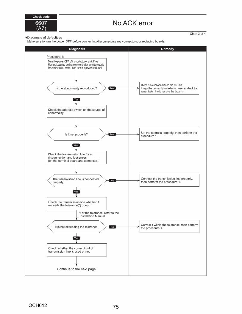
Check code
Diagnosis o e e ti esa e s e to t n t e po e OFF e o e onne ting is onne ting any onne to s, o epla ing oa s.
Diagnosis Remedy
66077
No C e oC a t 3 o 4
es
es
No
No
No
es
es
No
T e t ans ission line is onne te p ope ly.
It is not e ee ing t e tole an e.
C e t e t ans ission line et e it e ee s t e tole an e o not.
C e et e t e o e t in o t ans ission line is se o not.
Co e t it it in t e tole an e, t en pe o t e p o e e 1.
Conne t t e t ans ission line p ope ly, t en pe o t e p o e e 1.
Is t e a no ality ep o e
Is it set p ope ly
T e e is no a no ality on t e C nit.It ig t e a se y an e te nal noise, so e t e t ans ission line to e o e t e a to s .
Set t e a ess p ope ly, t en pe o t e p o e e 1.
C e t e a ess s it on t e so e o a no ality.
C e t e t ans ission line o a is onne tion an loosenesson t e te inal oa an onne to .
T n t e po e OFF o in oo o t oo nit, F es aste , Lossnay an e ote ont olle si ltaneo sly
o 2 in tes o o e, t en t n t e po e a ON.
P o e e 1
Contin e to t e ne t page
Fo t e tole an e, e e to t e Installation an al.
75OCH612
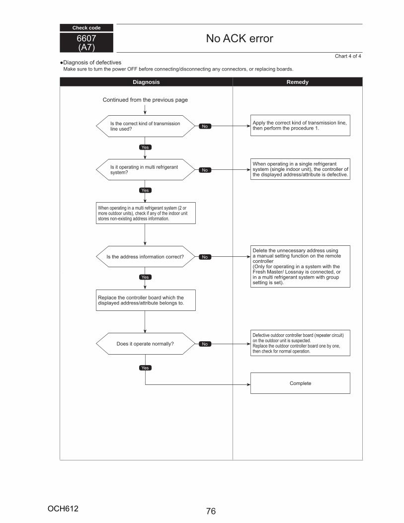
Check code
Diagnosis o e e ti esa e s e to t n t e po e OFF e o e onne ting is onne ting any onne to s, o epla ing oa s.
66077
No C e o
Diagnosis Remedy
C a t 4 o 4
es
es
es
es
No
No
No
NoIs t e o e t in o t ans ission line se
Is it ope ating in lti e ige ant syste
Is t e a ess in o ation o e t
Does it ope ate no ally
W en ope ating in a lti e ige ant syste 2 o o e o t oo nits , e i any o t e in oo nit
sto es non e isting a ess in o ation.
epla e t e ont olle oa i t e isplaye a ess att i te elongs to.
Contin e o t e p e io s page
De e ti e o t oo ont olle oa epeate i it on t e o t oo nit is s spe te .
epla e t e o t oo ont olle oa one y one, t en e o no al ope ation.
Delete t e nne essa y a ess sing a an al setting n tion on t e e ote ont olleOnly o ope ating in a syste it t e
F es aste Lossnay is onne te , o in a lti e ige ant syste it g o p setting is set .
W en ope ating in a single e ige ant syste single in oo nit , t e ont olle o t e isplaye a ess att i te is e e ti e.
pply t e o e t in o t ans ission line, t en pe o t e p o e e 1.
Co plete
76OCH612
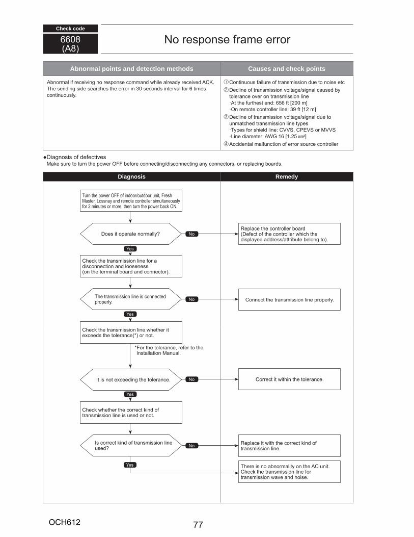
Check code
66088
Abnormal points and detection methods Causes and check points
no al i e ei ing no esponse o an ile al ea y e ei e C . T e sen ing si e sea es t e e o in 30 se on s inte al o 6 ti es ontin o sly.
Contin o s ail e o t ans ission e to noise et De line o t ans ission oltage signal a se y tole an e o e on t ans ission line
t t e t est en 656 t 200 ]On e ote ont olle line 39 t 12 ]
De line o t ans ission oltage signal e to n at e t ans ission line typesTypes o s iel line CVVS, CPEVS o VVSLine ia ete WG 16 1.25 E]
i ental al n tion o e o so e ont olle
Diagnosis o e e ti esa e s e to t n t e po e OFF e o e onne ting is onne ting any onne to s, o epla ing oa s.
Diagnosis Remedy
No esponse a e e o
Fo t e tole an e, e e to t e Installation an al.
es
es
es
es
No
No
No
No
Does it ope ate no ally
T e t ans ission line is onne te p ope ly.
It is not e ee ing t e tole an e.
Is o e t in o t ans ission line se
epla e t e ont olle oaDe e t o t e ont olle i t e isplaye a ess att i te elong to .
Conne t t e t ans ission line p ope ly.
Co e t it it in t e tole an e.
epla e it it t e o e t in o t ans ission line.
T e e is no a no ality on t e C nit.C e t e t ans ission line o t ans ission a e an noise.
T n t e po e OFF o in oo o t oo nit, F es aste , Lossnay an e ote ont olle si ltaneo sly
o 2 in tes o o e, t en t n t e po e a ON.
C e t e t ans ission line o a is onne tion an loosenesson t e te inal oa an onne to .
C e t e t ans ission line et e it e ee s t e tole an e o not.
C e et e t e o e t in o t ans ission line is se o not.
77OCH612
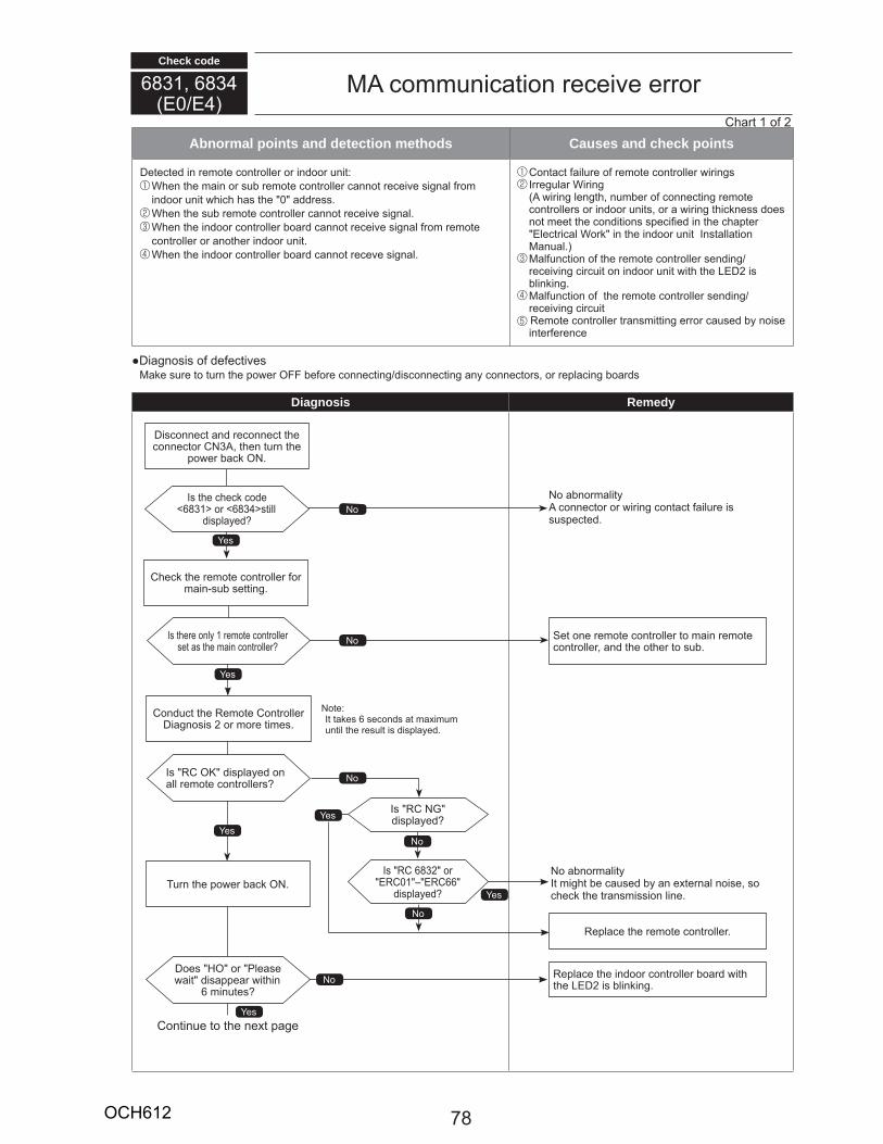
Check code
6831, 6834E0 E4
o ni ation e ei e e o
Abnormal points and detection methods Causes and check points
Dete te in e ote ont olle o in oo nit W en t e ain o s e ote ont olle annot e ei e signal o in oo nit i as t e 0 a ess. W en t e s e ote ont olle annot e ei e signal. W en t e in oo ont olle oa annot e ei e signal o e ote
ont olle o anot e in oo nit. W en t e in oo ont olle oa annot e e e signal.
Conta t ail e o e ote ont olle i ings I eg la Wi ing
i ing lengt , n e o onne ting e ote ont olle s o in oo nits, o a i ing t i ness oes
not eet t e on itions spe i e in t e apte Ele t i al Wo in t e in oo nit Installation an al.
al n tion o t e e ote ont olle sen inge ei ing i it on in oo nit it t e LED2 is lin ing.
al n tion o t e e ote ont olle sen inge ei ing i it e ote ont olle t ans itting e o a se y noise inte e en e
Diagnosis o e e ti esa e s e to t n t e po e OFF e o e onne ting is onne ting any onne to s, o epla ing oa s
Diagnosis Remedy
C e t e e ote ont olle o ain s setting.
Con t t e e ote Cont olle Diagnosis 2 o o e ti es.
Is C NG isplaye
T n t e po e a ON.
No
Is C 6832 o E C01 – E C66
isplaye
No a no alityIt ig t e a se y an e te nal noise, so
e t e t ans ission line.es
No
es
C a t 1 o 2
No
No
No
es
es
No
es
es
Is t e e o e 6831 o 6834 still
isplaye
Is t e e only 1 e ote ont olle set as t e ain ont olle
Does HO o Please ait isappea it in
6 in tes
Is C O isplaye on all e ote ont olle s
Set one e ote ont olle to ain e ote ont olle , an t e ot e to s .
Dis onne t an e onne t t e onne to CN3 , t en t n t e
po e a ON.
NoteIt ta es 6 se on s at a i
ntil t e es lt is isplaye .
Contin e to t e ne t page
No a no ality onne to o i ing onta t ail e is
s spe te .
epla e t e e ote ont olle .
epla e t e in oo ont olle oa it t e LED2 is lin ing.
78OCH612
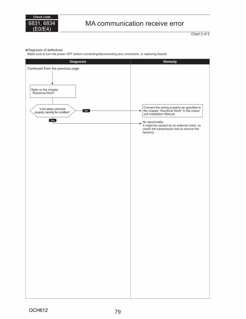
Check code
Diagnosis o e e ti esa e s e to t n t e po e OFF e o e onne ting is onne ting any onne to s, o epla ing oa s
Diagnosis Remedy
6831, 6834E0 E4
o ni ation e ei e e oC a t 2 o 2
No a no alityIt ig t e a se y an e te nal noise, so
e t e t ans ission line to e o e t e a to s .
No
es
Is the wiring connected properly, meeting the condition?
Conne t t e i ing p ope ly as spe i e in t e apte Ele t i al Wo in t e in oo nit Installation an al.
e e to t e apte Ele t i al Wo .
Contin e o t e p e io s page
79OCH612
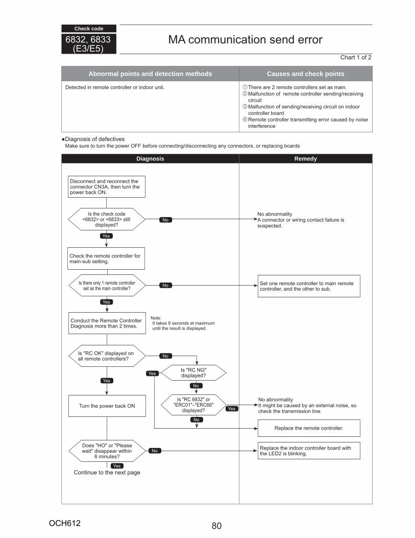
Check code
C a t 1 o 2
6832, 6833E3 E5
o ni ation sen e o
Abnormal points and detection methods Causes and check points
Dete te in e ote ont olle o in oo nit. T e e a e 2 e ote ont olle s set as ain. al n tion o e ote ont olle sen ing e ei ing
i it al n tion o sen ing e ei ing i it on in oo
ont olle oa e ote ont olle t ans itting e o a se y noise inte e en e
Diagnosis o e e ti esa e s e to t n t e po e OFF e o e onne ting is onne ting any onne to s, o epla ing oa s
Diagnosis Remedy
C e t e e ote ont olle o ain s setting.
Con t t e e ote Cont olle Diagnosis o e t an 2 ti es.
No
No
Is t e e o e 6832 o 6833 still
isplaye
Is t e e only 1 e ote ont olle set as t e ain ont olle
Set one e ote ont olle to ain e ote ont olle , an t e ot e to s .
Dis onne t an e onne t t e onne to CN3 , t en t n t e
po e a ON.
NoteIt ta es 6 se on s at a i
ntil t e es lt is isplaye .
No a no ality onne to o i ing onta t ail e is
s spe te .
es
Contin e to t e ne t page
Is C NG isplaye
T n t e po e a ON
No
Is C 6832 o E C01 – E C66
isplaye
No a no alityIt ig t e a se y an e te nal noise, so
e t e t ans ission line.es
No
es
No
es
es
NoDoes HO o Please
ait isappea it in 6 in tes
Is C O isplaye on all e ote ont olle s
epla e t e e ote ont olle .
epla e t e in oo ont olle oa it t e LED2 is lin ing.
es
80OCH612
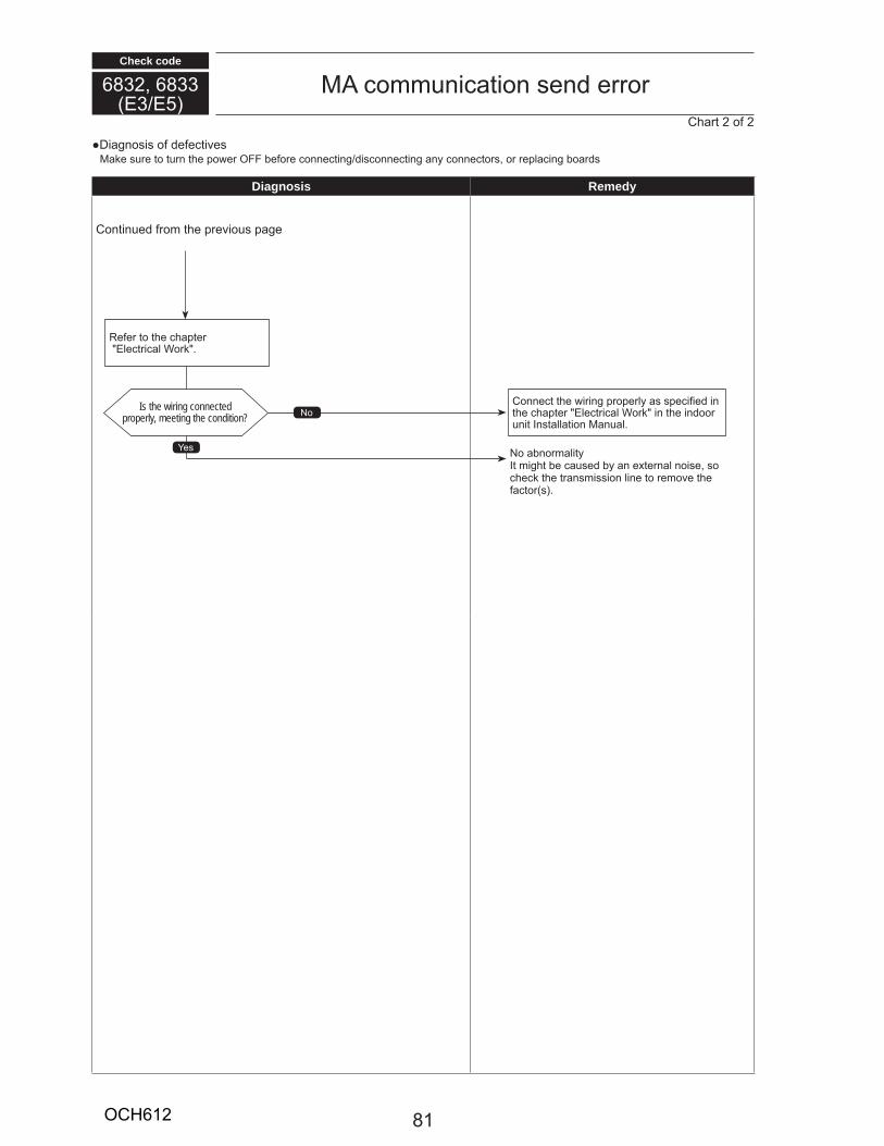
Check code
Diagnosis o e e ti esa e s e to t n t e po e OFF e o e onne ting is onne ting any onne to s, o epla ing oa s
Diagnosis Remedy
6832, 6833E3 E5
o ni ation sen e oC a t 2 o 2
No a no alityIt ig t e a se y an e te nal noise, so
e t e t ans ission line to e o e t e a to s .
No
es
Is the wiring connected properly, meeting the condition?
Conne t t e i ing p ope ly as spe i e in t e apte Ele t i al Wo in t e in oo nit Installation an al.
e e to t e apte Ele t i al Wo .
Contin e o t e p e io s page
81OCH612
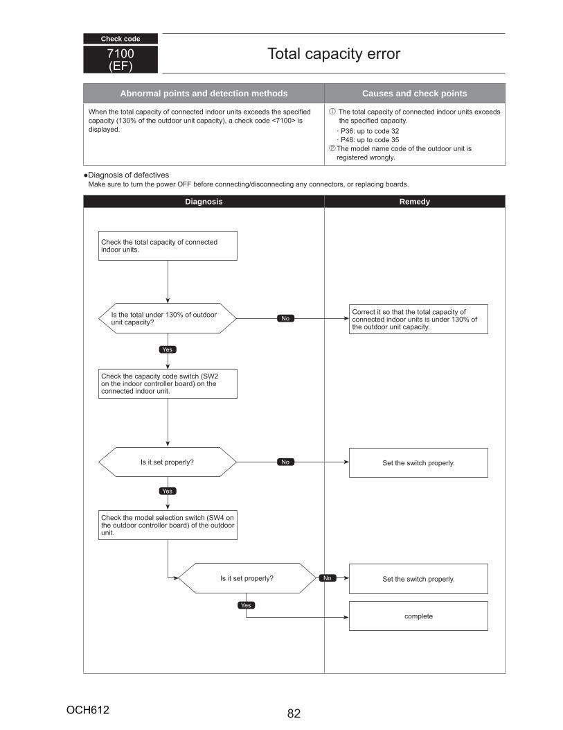
Check code
Abnormal points and detection methods Causes and check points
W en t e total apa ity o onne te in oo nits e ee s t e spe i eapa ity 130 o t e o t oo nit apa ity , a e o e 7100 isisplaye .
T e total apa ity o onne te in oo nits e ee s t e spe i e apa ity. P36 p to o e 32 P48 p to o e 35
T e o el na e o e o t e o t oo nit is egiste e ongly.
Diagnosis o e e ti esa e s e to t n t e po e OFF e o e onne ting is onne ting any onne to s, o epla ing oa s.
Diagnosis Remedy
7100EF
Total apa ity e o
No
es
es
No
No
es
Is it set p ope ly
Is it set p ope ly
Is t e total n e 130 o o t oo nit apa ity
C e t e apa ity o e s it SW2 on t e in oo ont olle oa on t e onne te in oo nit.
C e t e o el sele tion s it SW4 on t e o t oo ont olle oa o t e o t oo nit.
C e t e total apa ity o onne te in oo nits.
Co e t it so t at t e total apa ity oonne te in oo nits is n e 130 o
t e o t oo nit apa ity.
Set t e s it p ope ly.
Set t e s it p ope ly.
o plete
82OCH612
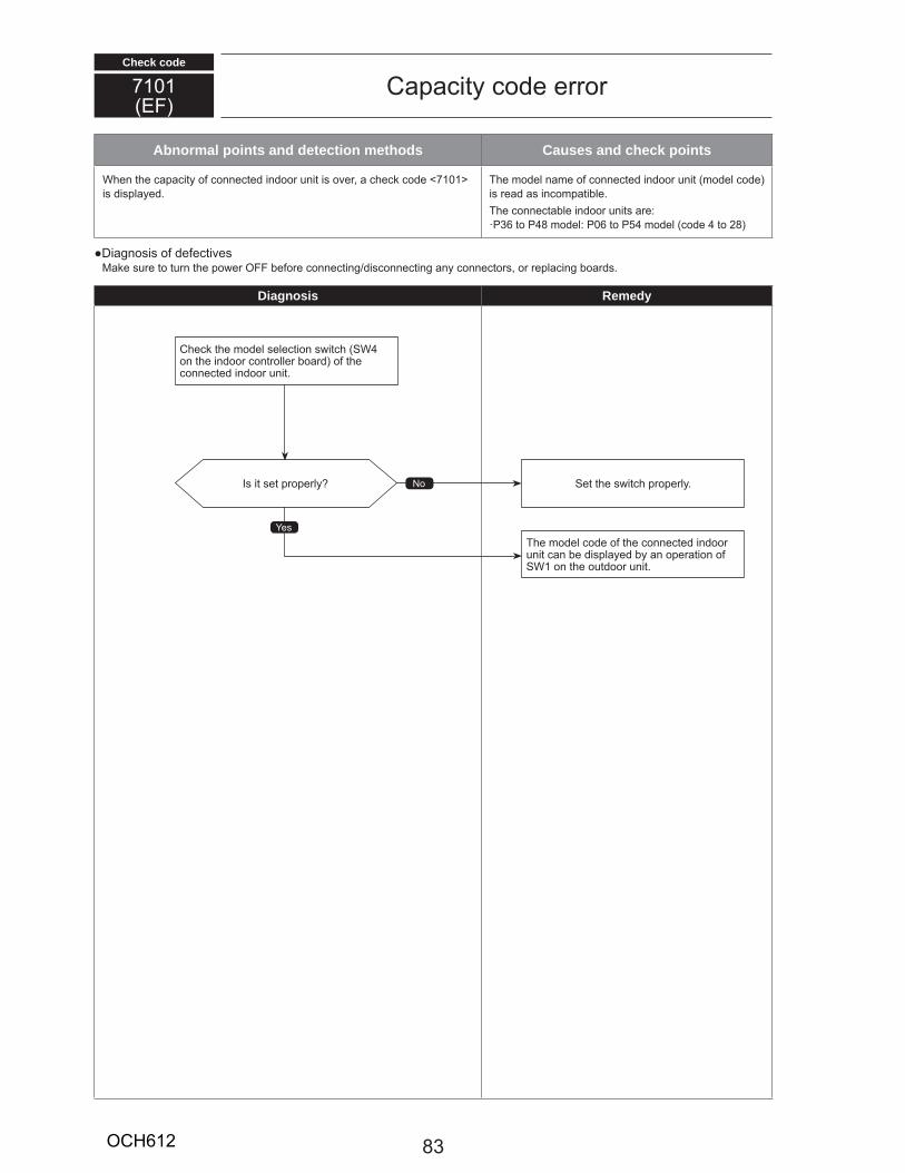
Check code
Abnormal points and detection methods Causes and check points
W en t e apa ity o onne te in oo nit is o e , a e o e 7101 is isplaye .
T e o el na e o onne te in oo nit o el o e is ea as in o pati le.T e onne ta le in oo nits a eP36 to P48 o el P06 to P54 o el o e 4 to 28
Diagnosis o e e ti esa e s e to t n t e po e OFF e o e onne ting is onne ting any onne to s, o epla ing oa s.
Diagnosis Remedy
7101EF
Capa ity o e e o
es
NoIs it set p ope ly Set t e s it p ope ly.
T e o el o e o t e onne te in oo nit an e isplaye y an ope ation o
SW1 on t e o t oo nit.
C e t e o el sele tion s it SW4 on t e in oo ont olle oa o t e onne te in oo nit.
83OCH612
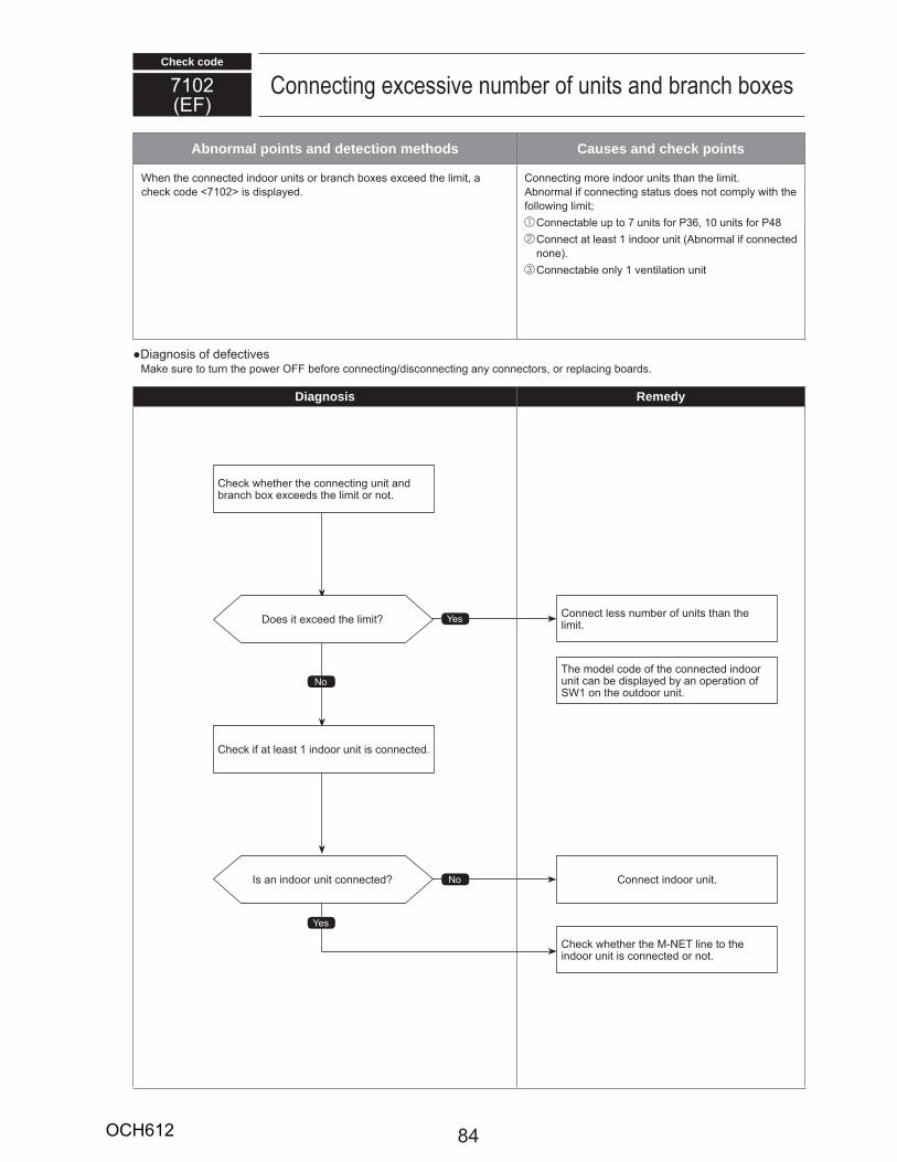
Check code
Abnormal points and detection methods Causes and check points
W en t e onne te in oo nits o an o es e ee t e li it, a e o e 7102 is isplaye .
Conne ting o e in oo nits t an t e li it.no al i onne ting stat s oes not o ply it t e
ollo ing li it Conne ta le p to 7 nits o P36, 10 nits o P48 Conne t at least 1 in oo nit no al i onne te none . Conne ta le only 1 entilation nit
Diagnosis o e e ti esa e s e to t n t e po e OFF e o e onne ting is onne ting any onne to s, o epla ing oa s.
Diagnosis Remedy
7102EF
Conne ting e essi e n e o nits an an o es
es
No
No
es
Is an in oo nit onne te
Does it e ee t e li it
Conne t in oo nit.
Conne t less n e o nits t an t e li it.
T e o el o e o t e onne te in oo nit an e isplaye y an ope ation o
SW1 on t e o t oo nit.
C e et e t e NET line to t e in oo nit is onne te o not.
C e i at least 1 in oo nit is onne te .
C e et e t e onne ting nit an an o e ee s t e li it o not.
84OCH612

Check code
Abnormal points and detection methods Causes and check points
T e a ess setting o o t oo nit o an o is ong. W ongly set a ess o an o
T e o t oo nit is not set in 000, o in t e ange o 51 to 100.
Diagnosis o e e ti esa e s e to t n t e po e OFF e o e onne ting is onne ting any onne to s, o epla ing oa s.
Diagnosis Remedy
7105EF
ess setting e o
<Outdoor unit>
es
NoIs t e a ess setting o e t
Set t e a ess p ope ly, t en t n t e po e OFF o in oo o t oo nit, an o , F es aste , Lossnay, an e ote ont olle si ltaneo sly o 2 in tes o o e, an t n t e po e a ON.
epla e t e o t oo ont olle oa .
C e et e t e o t oo nit a ess is set in 000, o in t e ange o 51 to 100.
85OCH612
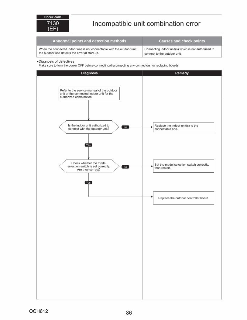
Check code
Abnormal points and detection methods Causes and check points
W en t e onne te in oo nit is not onne ta le it t e o t oo nit, t e o t oo nit ete ts t e e o at sta t p.
Conne ting in oo nit s i is not a t o i e to onne t to t e o t oo nit.
Diagnosis o e e ti esa e s e to t n t e po e OFF e o e onne ting is onne ting any onne to s, o epla ing oa s.
Diagnosis Remedy
7130EF
In o pati le nit o ination e o
NoIs t e in oo nit a t o i e to onne t it t e o t oo nit
epla e t e in oo nit s to t e onne ta le one.
e e to t e se i e an al o t e o t oo nit o t e onne te in oo nit o t e
a t o i e o ination.
es
No
es
C e et e t e o el sele tion s it is set o e tly.
e t ey o e tSet t e o el sele tion s it o e tly, t en esta t.
epla e t e o t oo ont olle oa .
86OCH612
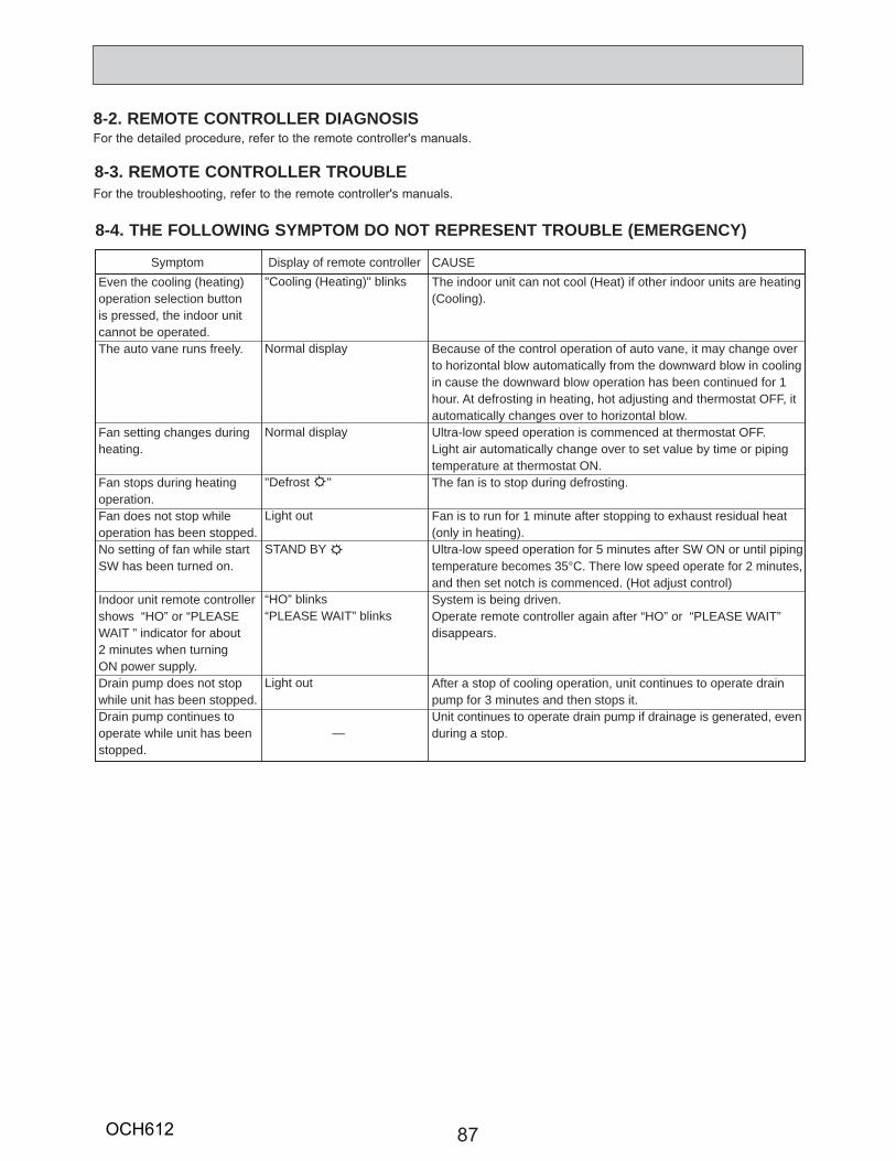
87
8-2. REMOTE CONTROLLER DIAGNOSISFor the detailed procedure, refer to the remote controller's manuals.
8-3. REMOTE CONTROLLER TROUBLEFor the troubleshooting, refer to the remote controller's manuals.
Even the cooling (heating) operation selection button is pressed, the indoor unit cannot be operated.The auto vane runs freely.
Fan setting changes duringheating.
Fan stops during heating operation.Fan does not stop while operation has been stopped.No setting of fan while start SW has been turned on.
Indoor unit remote controller shows “HO” or “PLEASE WAIT ” indicator for about 2 minutes when turning ON power supply.Drain pump does not stopwhile unit has been stopped.Drain pump continues to operate while unit has been stopped.
"Cooling (Heating)" blinks
Normal display
Normal display
"Defrost "
Light out
STAND BY
“HO” blinks“PLEASE WAIT” blinks
Light out
—
The indoor unit can not cool (Heat) if other indoor units are heating(Cooling).
Because of the control operation of auto vane, it may change overto horizontal blow automatically from the downward blow in cooling in cause the downward blow operation has been continued for 1 hour. At defrosting in heating, hot adjusting and thermostat OFF, it automatically changes over to horizontal blow.Ultra-low speed operation is commenced at thermostat OFF.Light air automatically change over to set value by time or piping temperature at thermostat ON.The fan is to stop during defrosting.
Fan is to run for 1 minute after stopping to exhaust residual heat (only in heating).Ultra-low speed operation for 5 minutes after SW ON or until piping temperature becomes 35°C. There low speed operate for 2 minutes, and then set notch is commenced. (Hot adjust control)System is being driven.Operate remote controller again after “HO” or “PLEASE WAIT”disappears.
After a stop of cooling operation, unit continues to operate drain pump for 3 minutes and then stops it.Unit continues to operate drain pump if drainage is generated, even during a stop.
Symptom Display of remote controller CAUSE
8-4. THE FOLLOWING SYMPTOM DO NOT REPRESENT TROUBLE (EMERGENCY)
OCH612
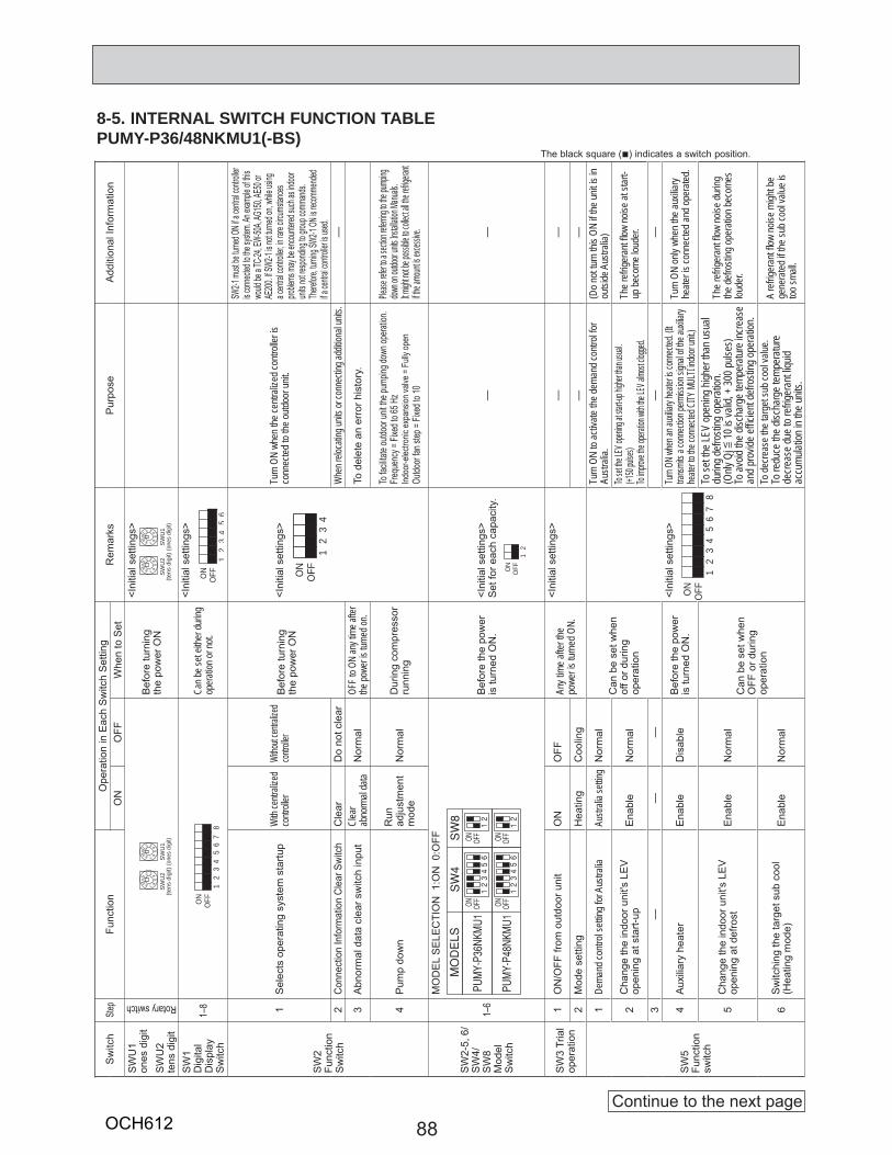
88
8-5. INTERNAL SWITCH FUNCTION TABLEPUMY-P36/48NKMU1(-BS)
Sw
itch
Step
Func
tion
Ope
ratio
n in
Eac
h S
witc
h S
ettin
gR
emar
ksP
urpo
seA
dditi
onal
Info
rmat
ion
ON
OFF
Whe
n to
Set
SW
U1
ones
dig
itS
WU
2 te
ns d
igit
Rotary switchB
efor
e tu
rnin
gth
e po
wer
ON
<Ini
tial s
ettin
gs>
SW
1 D
igita
lD
ispl
ayS
witc
h1–
8Ca
n be s
et eit
her d
uring
op
erati
on or
not.
<Ini
tial s
ettin
gs>
SW
2Fu
nctio
nS
witc
h
1S
elec
ts o
pera
ting
syst
em s
tartu
pW
ith ce
ntrali
zed
contr
oller
Witho
ut cen
tralize
dcon
troller
Bef
ore
turn
ing
the
pow
er O
N<I
nitia
l set
tings
>Tu
rn O
N wh
en th
e cen
traliz
ed co
ntroll
er is
co
nnec
ted to
the o
utdoo
r unit
.
SW2-1
must
be tu
rned O
N if a
centr
al con
troller
is c
onne
cted t
o the
syste
m. An
exam
ple of
this
would
be a T
C-24,
EW-50
A, AG
150, A
E50 o
r AE
200.
If SW2
-1 is n
ot tur
ned o
n, wh
ile usi
ng
a cen
tral co
ntrolle
r, in ra
re circ
umsta
nces
proble
ms m
ay be
encou
ntered
such
as ind
oor
units
not re
spond
ing to
grou
p com
mand
s. Th
erefor
e, tur
ning S
W2-1
ON is
recom
mend
ed
if a ce
ntral c
ontro
ller is
used.
2Co
nnec
tion
Info
rmat
ion
Clea
r Swi
tch
Cle
arD
o no
t cle
arW
hen r
eloca
ting u
nits o
r con
necti
ng ad
dition
al un
its.
—
3A
bnor
mal
dat
a cl
ear s
witc
h in
put
Clea
r ab
norm
al da
taN
orm
alOF
F to O
N an
y tim
e afte
r the
powe
r is tu
rned o
n.To
del
ete
an e
rror
his
tory
.
4P
ump
dow
nR
un
adju
stm
ent
mod
eN
orm
alD
urin
g co
mpr
esso
rru
nnin
g
To fa
cilitat
e outd
oor u
nit th
e pum
ping d
own o
perat
ion.
Frequ
ency
= Fix
ed to
65 H
zInd
oor-e
lectro
nic ex
pans
ion va
lve =
Fully
open
Outdo
or fan
step
= Fix
ed to
10
Please
refer t
o a se
ction re
ferring
to the
pump
ing
down o
n outd
oor un
its Ins
tallatio
n Manu
als.
It migh
t not be
possi
ble to
collec
t all th
e refrig
erant
if the a
mount
is exc
essive
.
SW
2-5,
6/
SW
4/S
W8
Mod
elS
witc
h
1–6
MO
DE
L S
ELE
CTI
ON
1:O
N 0
:OFF
Bef
ore
the
pow
eris
turn
ed O
N.
<Ini
tial s
ettin
gs>
Set
for e
ach
capa
city
.—
—
SW
3 Tr
ial
oper
atio
n1
ON
/OFF
from
out
door
uni
tO
NO
FFAn
y tim
e afte
r the
powe
r is tu
rned
ON.
<Ini
tial s
ettin
gs>
——
2M
ode
setti
ngH
eatin
gC
oolin
g—
—
SW
5Fu
nctio
nsw
itch
1De
mand
contr
ol se
tting f
or A
ustra
lia
Austr
alia s
etting
Nor
mal
Can
be
set w
hen
off o
r dur
ing
oper
atio
n
<Ini
tial s
ettin
gs>
Turn
ON
to ac
tivate
the d
eman
d con
trol fo
r Au
strali
a.(D
o not
turn t
his O
N if t
he un
it is i
n ou
tside
Aus
tralia
)
2C
hang
e th
e in
door
uni
t's L
EV
op
enin
g at
sta
rt-up
Ena
ble
Nor
mal
To set
the LE
V open
ing at
start-u
p high
er than
usual
.(+1
50 pul
ses)
To imp
rove th
e oper
ation w
ith the
LEV a
lmost c
logged
.Th
e refr
igera
nt fl o
w no
ise at
star
t-up
beco
me lo
uder.
3—
——
——
4A
uxili
ary
heat
erE
nabl
eD
isab
leB
efor
e th
e po
wer
is tu
rned
ON
.Tu
rn ON
when
an au
xiliary
heate
r is co
nnec
ted. (I
t tra
nsmi
ts a c
onne
ction p
ermiss
ion sig
nal o
f the a
uxilia
ry he
ater to
the c
onne
cted C
ITY M
ULTI
indoo
r unit
.)Tu
rn O
N on
ly wh
en th
e aux
iliary
heate
r is co
nnec
ted an
d ope
rated
.
5C
hang
e th
e in
door
uni
t's L
EV
op
enin
g at
def
rost
Ena
ble
Nor
mal
Can
be
set w
hen
OFF
or d
urin
g op
erat
ion
To se
t the L
EV op
ening
high
er th
an us
ual
durin
g defr
ostin
g ope
ratio
n.(O
nly Q
j [ 10
is va
lid, +
300 p
ulses
)To
avoid
the d
ischa
rge t
empe
ratur
e inc
reas
e an
d pro
vide e
ffi cien
t defr
ostin
g ope
ratio
n.
The r
efrige
rant
fl ow
noise
durin
g the
defro
sting
oper
ation
beco
mes
loude
r.
6S
witc
hing
the
targ
et s
ub c
ool
(Hea
ting
mod
e)E
nabl
eN
orm
alTo
decre
ase t
he ta
rget
sub c
ool v
alue.
To re
duce
the d
ischa
rge t
empe
ratur
e de
creas
e due
to re
friger
ant li
quid
accu
mulat
ion in
the u
nits.
A re
friger
ant fl
ow no
ise m
ight b
e ge
nera
ted if
the su
b coo
l valu
e is
too sm
all.
The black square (■) indicates a switch position.
1
ON
OFF
23
45
67
8
SW
U2
(tens
dig
it)
01 2 3 4
56789
SW
U1
(one
s di
git)
01 2 3 4
56789
1
ON
OFF
23
45
6
SW
U2
(tens
dig
it)
01 2 3 4
56789
SW
U1
(one
s di
git)
01 2 3 4
56789
1
ON
OFF
23
4
1
ON
OFF
2
1
ON
OFF
23
45
67
8
Continue to the next pageOCH612
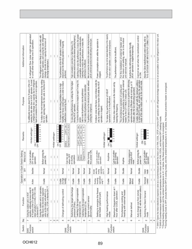
89
Sw
itch
Step
Func
tion
Ope
ratio
n in
Eac
h S
witc
h S
ettin
gR
emar
ksP
urpo
seA
dditi
onal
Info
rmat
ion
ONOF
FW
hen t
o Set
SW
5Fu
nctio
nsw
itch
7Du
ring t
he ou
tdoor
unit i
s in H
EAT
opera
tion,
addit
ionall
y inc
rease
abou
t 50
to 70
pulse
s of th
e LEV
open
ing on
the
indoo
r unit
whic
h is i
n FAN
, STO
P, CO
OL
or the
rmo-O
FF*1
.
Activ
e Ina
ctive
Can b
e set
when
OF
F or
durin
g op
erati
on
To ad
dition
ally i
ncrea
se ab
out 5
0 to 7
0 puls
es of
the L
EV
open
ing fo
r unit
s othe
r tha
n in H
EAT
opera
tion.
To av
oid
a ref
rigera
nt sh
ortag
e (le
ss ca
pacit
y) du
e to
refrig
erant
liquid
accu
mulat
ion in
the u
nits w
hich i
s not
in op
eratio
n.
A re
frige
rant
fl ow
noi
se m
ight
be
gene
rate
d in
uni
ts o
ther
than
the
one
in o
pera
tion.
8Du
ring t
he ou
tdoor
unit i
s in o
pera
tion,
fully
close
s the
elec
tronic
expa
nsion
va
lve on
the i
ndoo
r unit
whic
h is i
n FA
N, C
OOL,
STOP
, or t
herm
o-OF
F.*2
Enab
leNo
rmal
Befor
e tur
ning t
he
powe
r ON.
To re
duce
the
room
temp
eratu
re in
creas
e by
settin
g the
LEV
ope
ning
lower
for t
he u
nits
in the
rmo-
OFF
oper
ation
.
The r
efrige
rant
is mo
re lik
ely to
colle
ct in
the un
its w
ith
therm
o-OF
F op
erati
on, a
nd ca
using
the u
nits r
efrige
rant
shor
tage.
(Res
ults i
n les
s cap
acity
and i
ncre
ase o
f dis
char
ge te
mper
ature
.)
SW
6Fu
nctio
nsw
itch
1—
——
—<I
nitia
l set
tings
>—
—2
——
——
——
3—
——
——
—
4C
hang
e of
def
rost
ing
cont
rol
Enab
le(Fo
r high
hu
midit
y)No
rmal
Can
be
set
whe
n O
FF
or d
urin
g op
erat
ion
To sh
orten
the d
efros
ting p
rohib
ition t
ime i
n high
hu
midit
y (or
heav
y sno
w) re
gion,
in or
der t
o red
uce
malfu
nctio
ns ca
used
by fr
ost .
The p
erform
ance
of th
e HEA
T ope
ration
is so
mewh
at red
uced
sinc
e the
defro
sting
opera
tion i
s freq
uentl
y pe
rform
ed.
5—
——
——
6S
witc
hing
the
targ
et d
isch
arge
pres
sure
(Pdm
)En
able
Norm
alTo
raise
the p
erfor
manc
e by s
etting
the P
dm hi
gher
du
ring H
EAT
oper
ation
.Po
wer co
nsump
tion is
raised
due to
a high
er fre
quency
. (The
perfor
mance
would
not be
raise
at the
maxim
um op
erating
freque
ncy.)
7Sw
itchin
g (1)
the t
arge
t eva
pora
tion
tempe
ratur
e (ET
m)En
able
Norm
alTo
raise/re
duce th
e perfo
rmance
by ch
anging
the tar
get ET
m durin
g COO
L ope
ration.
Switch
to rais
e the p
erforma
nce: ra
ises th
e perfo
rmance
Switch
to red
uce the
perfor
mance
: preve
nts de
w cond
ensatio
n
Switc
hing i
t to ra
ise th
e per
forma
nce,
it rais
es th
e pow
er
cons
umpti
on, a
nd pr
oduc
es m
ore d
ew co
nden
satio
n.Sw
itchin
g it to
redu
ce th
e perf
orman
ce, it
mak
es th
e pe
rform
ance
insu
ffi cien
t.8
Switc
hing (
2) th
e tar
get e
vapo
ratio
ntem
pera
ture (
ETm)
Enab
leNo
rmal
SW
7Fu
nctio
nsw
itch
1Ig
nore
cur
rent
sen
sor
abno
rmal
ityEn
able
Norm
alA
fter t
urni
ng
the
pow
er O
N.
<Ini
tial s
ettin
gs>
To pe
rform
a tes
t run
for e
lectric
al pa
rts al
one w
ithou
t ru
nning
the c
ompr
esso
r. Ma
ke sur
e to co
nnect t
he con
nectors
to the
comp
ressor
after c
hecking
the ele
ctrical
parts.B
e care
ful not
to get
electri
cal sho
ck while
workin
g on e
lectrica
l parts.
2S
ettin
g to
ene
rgiz
e th
e fre
eze
stat
hea
ter (
optio
nal p
art)
Dur
ing
heat
ing
oper
atio
n on
ly*3
Includ
e wh
en th
e he
ating
op
erati
on is
OF
F. *4
Can
be
set w
hen
OFF
or d
urin
g op
erat
ion
It red
uces
snow
on th
e bas
e, ev
en it
blows
insid
e the
un
it, by
settin
g the
base
heate
r ON
while
the H
EAT
oper
ation
is st
oppe
d.Po
wer c
onsu
mptio
n rais
es w
hile t
he op
erati
on is
sto
pped
.
3H
igh
heat
ing
perfo
rman
ce
mod
eEn
able
Norm
alA
nytim
eTo
rais
e th
e pe
rform
ance
of H
EAT
op
erat
ion
if it
is in
suffi
cien
t.Th
e perf
orman
ce m
ay no
t be r
aised
depe
nding
on th
e cap
acity
of
indoo
r unit
s in o
perat
ion, o
r outs
ide ai
r temp
eratur
e.
4M
axim
um fr
eque
ncy
dow
n at
1
hour
afte
r CO
OL
oper
atio
nEn
able
Norm
alCa
n be s
et wh
en
OFF
or du
ring
oper
ation
To re
duce
dew
cond
ensa
tion o
n the
indo
or un
it by
lower
ing th
e fre
quen
cy.
The p
erfor
manc
e migh
t be i
nsuffi
cien
t.
5S
imul
tane
ous
cool
ing
and
heat
ing
with
ext
erna
l hea
ter
Enab
leDi
sable
Anyti
meTh
e sim
ulta
neou
s op
erat
ion
of c
oolin
g an
d he
atin
g wi
ll be
poss
ible
by
inst
allin
g an
ext
erna
l he
ater
to th
e CI
TY M
ULTI
indo
or u
nit.
For t
he in
stal
latio
n of
ext
erna
l hea
ter a
nd
the
indo
or u
nit s
ettin
g, re
fer t
o th
e in
door
un
it se
rvic
e m
anua
l.
6M
anua
l def
rost
Manu
al de
frost
Norm
alDu
ring c
ompre
ssor
runnin
g in H
EAT
mode
.
Turn
ON
when
it is
nece
ssar
y to p
erfor
m the
defro
sting
op
erati
on fo
rcedly
. (Effe
ctive
only
at sta
rt-up
, or 1
0 mi
nutes
after
the l
ast d
efros
ting o
pera
tion)
It per
forms
the d
efros
ting o
pera
tion f
orce
dly.
(HEA
T op
erati
on is
stop
ped t
empo
rarily
.)
SW
9Fu
nctio
nS
witc
h
1Au
to c
hang
e ov
er fr
om re
mot
e co
ntro
ller (
IC w
ith th
e mini
mum
addre
ss)
Enab
leDi
sable
Befor
e tur
ning t
he
powe
r ON
<Ini
tial s
ettin
gs>
Enab
les th
e ind
oor u
nit w
ith th
e mini
mum
addr
ess
to se
lect A
UTO
mode
, and
switc
hes t
he op
erati
on
mode
of th
e othe
r indo
or un
its to
the s
ame m
ode.
Can
not b
e se
t whe
n th
e ce
ntra
lized
con
trol
is O
N.
2Sw
itchi
ng th
e Si
lent
/ Dem
and
mod
eDe
mand
co
ntrol
Silen
t mo
deCa
n be s
et wh
en
OFF
or du
ring
oper
ation
—Ab
out th
e Sile
nt mo
de/D
eman
d con
trol s
etting
, refer
to
"8-10
. OUT
DOOR
UNI
T INP
UT/O
UTPU
T CON
NECT
OR".
3—
——
——
—4
——
——
——
*1
SW
5-7
Ope
ns th
e in
door
- ele
ctro
nic e
xpan
sion
valve
as
a co
unte
rmea
sure
aga
inst
the
indo
or u
nit i
n FA
N, C
OO
L, S
TOP,
or t
herm
o-O
FF o
pera
tion
with
refri
gera
nt-s
horta
ge s
tatu
s du
e to
an
accu
mul
atio
n of
liqui
d re
frige
rant
in th
e in
door
uni
t.
*2 S
W5-
8 C
ount
erm
easu
re a
gain
st ro
om te
mpe
ratu
re ri
se fo
r ind
oor u
nit i
n FA
N, C
OO
L, a
nd th
erm
o-O
FF (h
eatin
g) m
ode.
*3
Dur
ing
heat
ing
oper
atio
n an
d th
e am
bien
t tem
pera
ture
is 4:
or b
elow
, the
free
ze p
reve
ntio
n he
ater
is e
nerg
ized
.
*4 D
urin
g he
atin
g m
ode
is O
FF (i
nclu
de th
erm
o-O
FF in
coo
ling
mod
e), a
nd th
e am
bien
t tem
pera
ture
is 4:
or b
elow
, the
free
ze p
reve
ntio
n he
ater
is e
nerg
ized
.
SW
6-6
OFF
ON
Targe
t Pdm
(kg/c
m²)
31.5
33.5
SW
6-7
OFF
ON
OFF
ON
SW
6-8
OFF
OFF
ON
ON
Targ
et E
Tm (:
)9
116
14
1
ON
OFF
23
45
67
8
<Ini
tial s
ettin
gs>
1
ON
OFF
23
45
67
8
1
ON
OFF
23
45
6
1
ON
OFF
23
4
OCH612
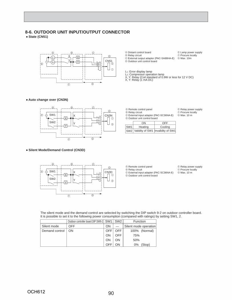
90
CN51
X
543
A C
D
5E
1
1
3
B
G
Y
L1: Error display lampL2: Compressor operation lampX, Y: Relay (Coil standard of 0.9W or less for 12 V DC)
F
A C
D
E
B
GF
CN3NX
Y
SW1
SW2
123
X, Y: Relay (1 mA DC)
SW1SW2
ONHeating
Validity of SW1
OFFCooling
Invalidity of SW1
1
3
A C
D
E
B
GF
CN3DX
Y
SW1
SW2
123
The silent mode and the demand control are selected by switching the DIP switch 9-2 on outdoor controller board.It is possible to set it to the following power consumption (compared with ratings) by setting SW1, 2.
Silent mode Silent mode operationOutdoor controller board DIP SW9-2 SW1 SW2 Function
Demand controlOFFON
ONOFFON
—OFFOFF
ONOFF
ONON
100% 75%50%0%
(Normal)
(Stop)
A Distant control boardB Relay circuitC External output adapter (PAC-SA88HA-E)D Outdoor unit control board
A Remote control panelB Relay circuitC External input adapter (PAC-SC36NA-E)D Outdoor unit control board
E Relay power supplyF Procure locallyG Max. 10 m
A Remote control panelB Relay circuitC External input adapter (PAC-SC36NA-E)D Outdoor unit control board
E Relay power supplyF Procure locallyG Max. 10 m
E Lamp power supplyF Procure locallyG Max. 10m
~
~
YX
Y
X
~
Y
X
L1
L2
8-6. OUTDOOR UNIT INPUT/OUTPUT CONNECTOR State (CN51)
Auto change over (CN3N)
Silent Mode/Demand Control (CN3D)
OCH612
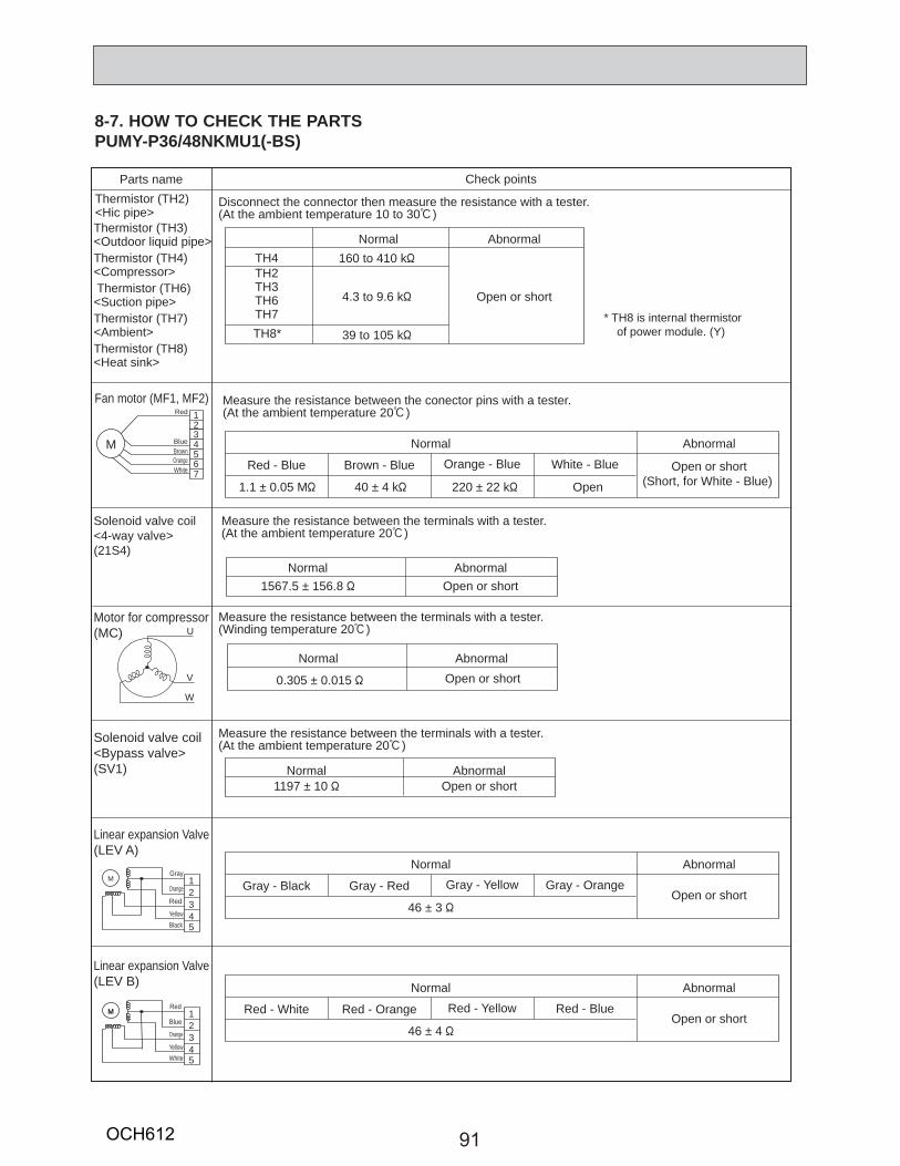
91
M 12345
MRed
Blue
Orange
YellowWhite
Parts name Check points
Disconnect the connector then measure the resistance with a tester. (At the ambient temperature 10 to 30:)
Thermistor (TH3)<Outdoor liquid pipe>Thermistor (TH4)<Compressor> Thermistor (TH6)<Suction pipe>Thermistor (TH7)<Ambient> Thermistor (TH8)<Heat sink>
Normal160 to 410 k"
4.3 to 9.6 k"
39 to 105 k"
TH4TH2TH3TH6TH7
TH8*
Abnormal
Open or short
Measure the resistance between the terminals with a tester. (At the ambient temperature 20:)
Solenoid valve coil<4-way valve> (21S4)
Motor for compressor(MC)
Measure the resistance between the terminals with a tester.(At the ambient temperature 20:)
Normal1197 ± 10 "
AbnormalOpen or short
Solenoid valve coil<Bypass valve> (SV1)
Linear expansion Valve(LEV A)
Linear expansion Valve(LEV B)
Measure the resistance between the terminals with a tester. (Winding temperature 20:)
W
V
U
* TH8 is internal thermistor of power module. (Y)
Normal1567.5 ± 156.8 "
1.1 ± 0.05 M" 40 ± 4 k" 220 ± 22 k" Open
AbnormalOpen or short
Normal
0.305 ± 0.015 "
AbnormalOpen or short
Normal
Gray - Black Gray - Red Gray - Yellow Gray - Orange
Abnormal
46 ± 3 "Open or short
Normal
Red - White Red - Orange Red - Yellow Red - Blue
Abnormal
46 ± 4 "Open or short
Normal
Red - Blue Brown - Blue Orange - Blue White - Blue
Abnormal
Thermistor (TH2)<Hic pipe>
12345
MGray
Orange
Red
YellowBlack
Red
BlueBrownOrangeWhite
Measure the resistance between the conector pins with a tester.(At the ambient temperature 20:)
Fan motor (MF1, MF2)
M
1234567
Open or short(Short, for White - Blue)
8-7. HOW TO CHECK THE PARTSPUMY-P36/48NKMU1(-BS)
OCH612
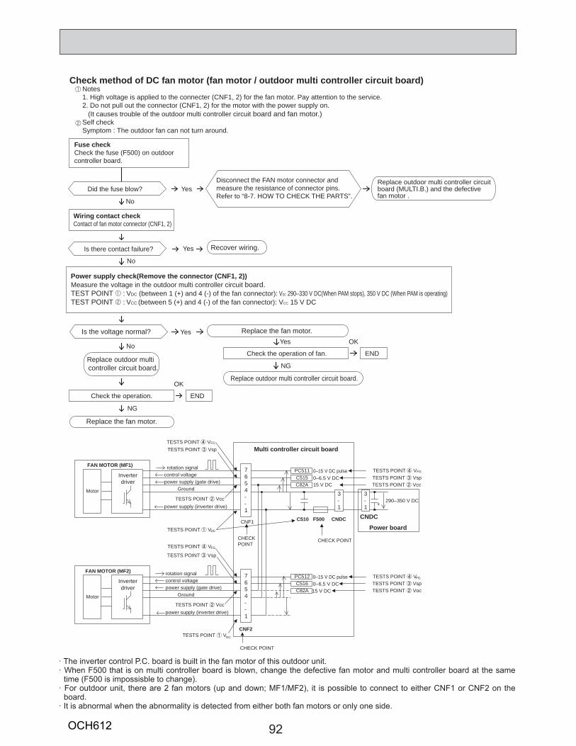
92
Notes1. High voltage is applied to the connecter (CNF1, 2) for the fan motor. Pay attention to the service.2. Do not pull out the connector (CNF1, 2) for the motor with the power supply on. (It causes trouble of the outdoor multi controller circuit board and fan motor.)Self checkSymptom : The outdoor fan can not turn around.
1
2
Check method of DC fan motor (fan motor / outdoor multi controller circuit board)
Power supply check(Remove the connector (CNF1, 2))Measure the voltage in the outdoor multi controller circuit board.TEST POINT 1 : VDC (between 1 (+) and 4 (-) of the fan connector): VDC 290–330 V DC(When PAM stops), 350 V DC (When PAM is operating)TEST POINT 2 : VCC (between 5 (+) and 4 (-) of the fan connector): VCC 15 V DC
No
NG
NG
Wiring contact checkContact of fan motor connector (CNF1, 2)
Fuse checkCheck the fuse (F500) on outdoorcontroller board.
Recover wiring.
Replace outdoor multi controller circuit board.
Replace the fan motor.
Replace outdoor multi controller circuitboard (MULTI.B.) and the defectivefan motor .
Replace outdoor multi controller circuit board.
Replace the fan motor.
Is the voltage normal?
Is there contact failure? Yes
Yes
No
Did the fuse blow?
No
Yes
Check the operation of fan. END
Yes OK
Check the operation. END
OK
Disconnect the FAN motor connector and measure the resistance of connector pins.Refer to “8-7. HOW TO CHECK THE PARTS”.
Inverterdriver
Ground
power supply (inverter drive)
power supply (gate drive)
rotation signal control voltage
7654--1
3-1
CNF1
15 V DC0–6.5 V DC0–15 V DC pulse
Motor
TESTS POINT VDC
TESTS POINT Vcc
CHECK POINT
+290–350 V DC
TESTS POINT VspPC511C515
TESTS POINT VFG
C82A
TESTS POINT VspTESTS POINT VFG
TESTS POINT Vcc
CHECK POINT
Inverterdriver
Ground
power supply (inverter drive)
power supply (gate drive)
rotation signal control voltage
7654--1
0–6.5 V DC0–15 V DC pulse
Motor
TESTS POINT VDC
TESTS POINT VspPC512C516
15 V DC TESTS POINT VocC82A
TESTS POINT VFG
TESTS POINT Vsp
TESTS POINT VFG
TESTS POINT Vcc
CHECK POINT
3-1
Multi controller circuit board
Power board
CNDCC510 F500 CNDC
CNF2
FAN MOTOR (MF1)
FAN MOTOR (MF2)
· The inverter control P.C. board is built in the fan motor of this outdoor unit.· When F500 that is on multi controller board is blown, change the defective fan motor and multi controller board at the same
time (F500 is impossisble to change).· For outdoor unit, there are 2 fan motors (up and down; MF1/MF2), it is possible to connect to either CNF1 or CNF2 on the
board.· It is abnormal when the abnormality is detected from either both fan motors or only one side.
OCH612
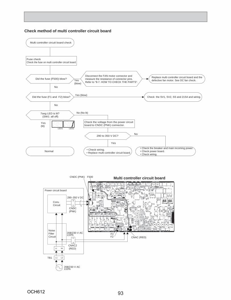
93
Check method of multi controller circuit board
Normal
LED1 LED2
Fuse checkCheck the fuse on multi controller circuit board
Did the fuse (F500) blow? Replace multi controller circuit board and the defective fan motor. See DC fan check.
Did the fuse (F1 and F2) blow? Check the SV1, SV2, SS and 21S4 and wiring.
7seg LED is lit?(SW1: all off)
290 to 350 V DC?
Check wiring. Replace multi controller circuit board.
Check the breaker and main incoming power. Check power board. Check wiring.
Check the voltage from the power circuit board to CNDC (PNK) connector.
No
No
Yes(lit)
No (No lit)
Yes
No
Multi controller circuit board check
Yes (blow)
Yes (blow)
CNDC (PNK)
Power circuit board
3
1
CNDC(PNK)
CNAC2(RED)
NoiseFilterCircuit
Conv.Circuit
Multi controller circuit board
290–350 V DC
208/230 V AC±10%
208/230 V AC
TB1
±10%
CNAC (RED)F1F2
F500
1
3
LI NI
L1 L2
Disconnect the FAN motor connector and measure the resistance of connector pins.Refer to “8-7. HOW TO CHECK THE PARTS”.
OCH612
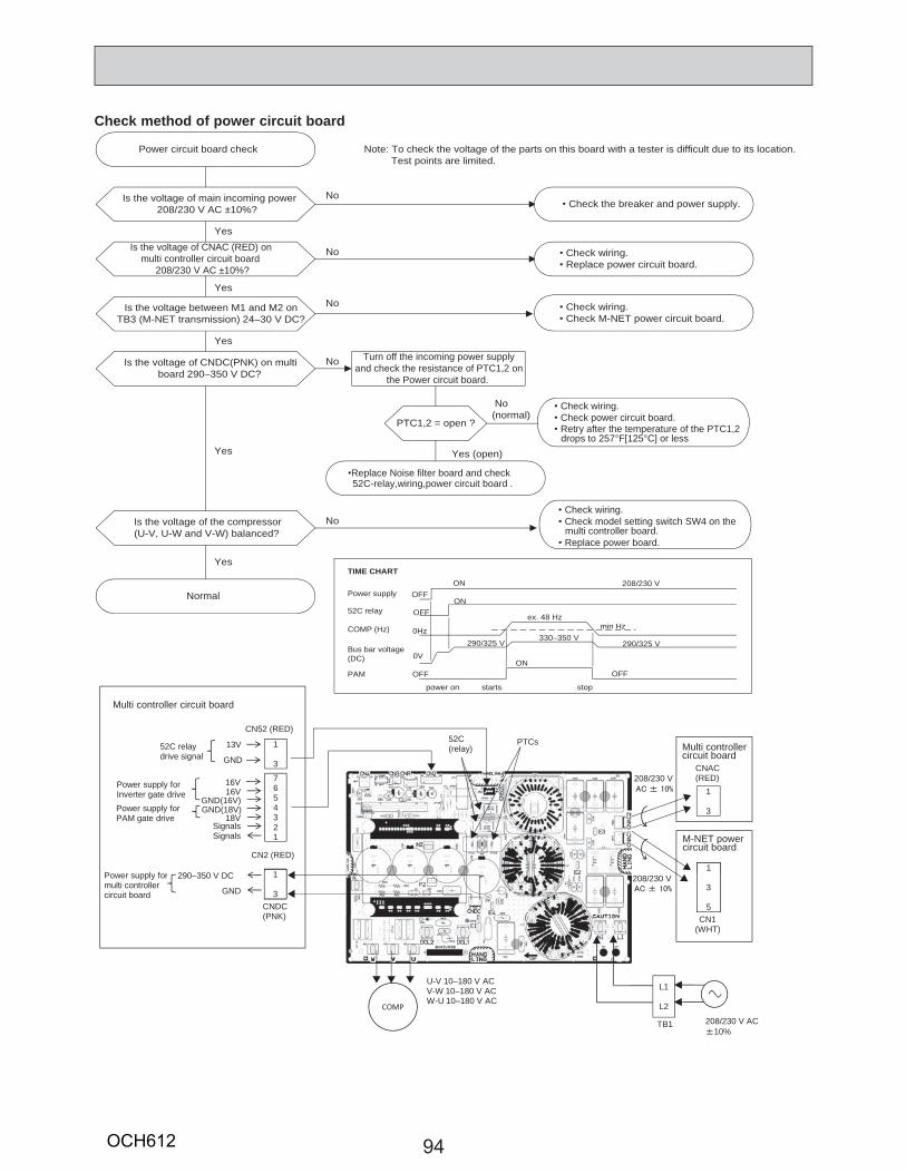
94
Check method of power circuit board
Is the voltage of main incoming power208/230 V AC ±10%? Check the breaker and power supply.
Is the voltage of CNAC (RED) on multi controller circuit board
208/230 V AC ±10%?
Check wiring. Replace power circuit board.
Is the voltage of CNDC(PNK) on multiboard 290–350 V DC?
Check wiring. Check power circuit board. Retry after the temperature of the PTC1,2 drops to 257°F[125°C] or less
Note: To check the voltage of the parts on this board with a tester is difficult due to its location. Test points are limited.
Yes
Yes
Yes
Yes
No
No
No
No
Is the voltage between M1 and M2 onTB3 (M-NET transmission) 24–30 V DC?
Check wiring. Check M-NET power circuit board.
No
Turn off the incoming power supplyand check the resistance of PTC1,2 on
the Power circuit board.
PTC1,2 = open ?
Yes (open)
Replace Noise filter board and check52C-relay,wiring,power circuit board .
Check wiring. Check model setting switch SW4 on the multi controller board. Replace power board.
No(normal)
Power circuit board check
Normal
Yes
Is the voltage of the compressor(U-V, U-W and V-W) balanced?
1
3
CNAC(RED)
1
Multi controllercircuit board
M-NET powercircuit board
52C(relay)
PTCs
208/230 V
Multi controller circuit board
CN2 (RED)
CN52 (RED)
13V
GND
16V16V
GND(16V)GND(18V)
18V
SignalsSignals
7654321
1
3
52C relaydrive signal
Power supply for Inverter gate drivePower supply for PAM gate drive
L1
L2
TB1 208/230 V AC10%
3
5CN1
(WHT)
COMP
U-V 10–180 V ACV-W 10–180 V ACW-U 10–180 V AC
208/230 V
CNDC(PNK)
290–350 V DC
GND
1
3
Power supply formulti controller circuit board
Power supply
52C relay
Bus bar voltage(DC)
COMP (Hz)
PAM OFF
OFFON
OFFON
0Hz
ex. 48 Hz
0V
290/325 V330–350 V
ON
208/230 V
min Hz
290/325 V
OFF
TIME CHART
power on starts stop
OCH612
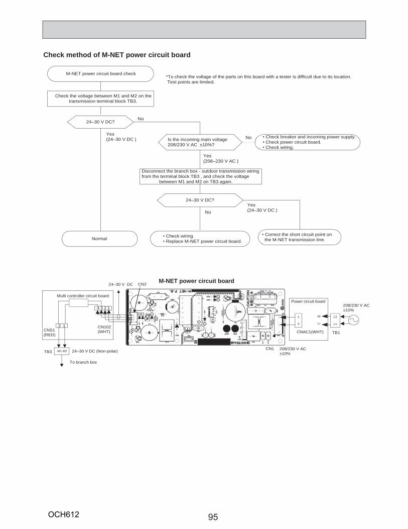
95
Check method of M-NET power circuit board
Normal
24–30 V DC?
Correct the short circuit point on the M-NET transmission line.
24–30 V DC?
Is the incoming main voltage208/230 V AC ±10%?
Check wiring. Replace M-NET power circuit board.
Check breaker and incoming power supply. Check power circuit board. Check wiring.
Check the voltage between M1 and M2 on thetransmission terminal block TB3.
Disconnect the branch box - outdoor transmission wiringfrom the terminal block TB3 , and check the voltage
between M1 and M2 on TB3 again.
*To check the voltage of the parts on this board with a tester is difficult due to its location. Test points are limited.
No
Yes(24–30 V DC ) No
Yes(208–230 V AC )
NoYes(24–30 V DC )
M-NET power circuit board check
Power circuit board
1
3
CNAC1(WHT)
Multi controller circuit board
M1 M2
CNS1(RED)
2 1 CN102(WHT)
TB3
4 3 2 1208/230 V AC±10%
NI
LI
208/230 V AC±10%
CN1
CN224–30 V DC
24–30 V DC (Non-polar)
To branch box
M-NET power circuit board
L2
L1
TB1
OCH612
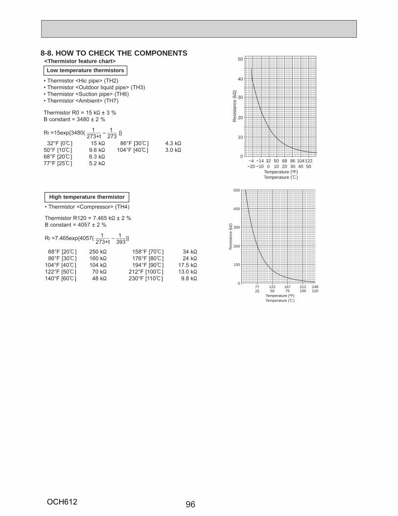
96
8-8. HOW TO CHECK THE COMPONENTS<Thermistor feature chart>Low temperature thermistors
• Thermistor <Hic pipe> (TH2)• Thermistor <Outdoor liquid pipe> (TH3)• Thermistor <Suction pipe> (TH6)• Thermistor <Ambient> (TH7)
32°F [0:] 15 k"50°F [10:] 9.6 k"68°F [20:] 6.3 k"77°F [25:] 5.2 k"
86°F [30:] 4.3 k"104°F [40:] 3.0 k"
Thermistor R0 = 15 k" ± 3 %B constant = 3480 ± 2 %
Rt =15exp{3480( 273+t – 273 )}1 1
Thermistor R120 = 7.465 k" ± 2 %B constant = 4057 ± 2 %
Rt =7.465exp{4057( 273+t – 393)}1 1
68°F [20:] 250 k" 86°F [30:] 160 k"104°F [40:] 104 k"122°F [50:] 70 k"140°F [60:] 48 k"
158°F [70:] 34 k" 176°F [80:] 24 k" 194°F [90:] 17.5 k"212°F [100:] 13.0 k"230°F [110:] 9.8 k"
High temperature thermistor
• Thermistor <Compressor> (TH4)
0
10
20
30
40
50
20 10 0 10 20 30 40 504 14 32 50 68 86 104122
Temperature (:)Temperature (ºF)
Res
ista
nce
(k"
)
500
400
300
200
100
0
25 50 75 100 12077 122 167 212 248
Temperature (ºF)Temperature (:)
Res
ista
nce
(k"
)
OCH612
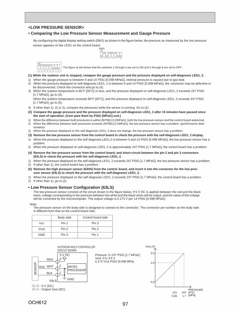
97
Comparing the Low Pressure Sensor Measurement and Gauge PressureBy configuring the digital display setting switch (SW1) as shown in the figure below, the pressure as measured by the low pressure sensor appears on the LED1 on the control board.
(1) While the outdoor unit is stopped, compare the gauge pressure and the pressure displayed on self-diagnosis LED1, 2.1) When the gauge pressure is between 0 and 14 PSIG [0.098 MPaG], internal pressure is caused due to gas leak. 2) When the pressure displayed on self-diagnosis LED1, 2 is between 0 and 14 PSIG [0.098 MPaG], the connector may be defective or
be disconnected. Check the connector and go to (4). 3)
4) If other than 1), 2) or 3), compare the pressures while the sensor is running. Go to (2).(2) Compare the gauge pressure and the pressure displayed on self-diagnosis LED1, 2 after 15 minutes have passed since
the start of operation. (Com pare them by PSIG [MPaG] unit.)1) When the difference between both pressures is within 29 PSIG [ 0.2MPaG], both the low pressure sensor and the control board are normal.2) When the difference between both pressures exceeds 29 PSIG [ 0.2MPaG], the low pressure sensor has a problem. (performance dete-
rioration) 3) When the pressure displayed on the self-diagnosis LED1, 2 does not change, the low pressure sensor has a problem.(3) Remove the low pressure sensor from the control board to check the pressure with the self-diagnosis LED1, 2 display.1) When the pressure displayed on the self-diagnosis LED1,2 is between 0 and 14 PSIG [0.098 MPaG], the low pressure sensor has a
problem.2) When the pressure displayed on self-diagnosis LED1, 2 is approximately 247 PSIG [1.7 MPaG], the control board has a problem.
(4) Remove the low pressure sensor from the control board, and short-circuit between the pin 2 and pin 3 connectors (63LS) to check the pressure with the self-diagnosis LED1, 2.
1) When the pressure displayed on the self-diagnosis LED1, 2 exceeds 247 PSIG [1.7 MPaG], the low pressure sensor has a problem. 2) If other than 1), the control board has a problem.(5) Remove the high pressure sensor (63HS) from the control board, and insert it into the connector for the low pres-
sure sensor (63LS) to check the pressure with the self-diagnosis LED1, 2.1) When the pressure displayed on the self-diagnosis LED1, 2 exceeds 247 PSIG [1.7 MPaG], the control board has a problem. 2) If other than 1), go to (2).
Low Pressure Sensor Configuration (63LS)The low pressure sensor consists of the circuit shown in the figure below. If 5 V DC is applied between the red and the black wires, voltage corresponding to the pressure between the white and the black wires will be output, and the value of this voltagewill be converted by the microcomputer. The output voltage is 0.173 V per 14 PSIG [0.098 MPaG].
The pressure sensor on the body side is designed to connect to the connector. The connector pin number on the body side is different from that on the control board side.
SW1ON
1 2 3 4 5 6 7 8
ON
1 2 3 4 5 6 7 8
The figure at left shows that the switches 1 through 4 are set to ON and 5 through 8 are set to OFF.
Body side Control board side
Vcc Pin 1 Pin 3
Vout Pin 2 Pin 2
GND Pin 3 Pin 1
Note:
0.5
0.85 1.7
2.5
3.5
Vout (V)
PRESSURE (PSI)(MPa)
3
2
1
RED
WHT
BLKSE
NS
OR
5 V DC
GND63LS
Vout MICROPROCESSOR
3–1 : 5 V (DC)2–1 : Output Vout (DC)
OUTDOOR MULTI CONTROLLER CIRCUIT BOARD
Pressure: 0–247 PSIG [1.7 MPaG]Vout: 0.5–3.5 V0.173 V/14 PSIG [0.098 MPa]
<LOW PRESSURE SENSOR>
123 247
When the outdoor temperature is 86°F [30°C] or less, and the pressure displayed on self-diagnosis LED1, 2 exceeds 247 PSIG [1.7 MPaG], go to (3). When the outdoor temperature exceeds 86°F [30°C], and the pressure displayed on self-diagnosis LED1, 2 exceeds 247 PSIG [1.7 MPaG], go to (5).
OCH612
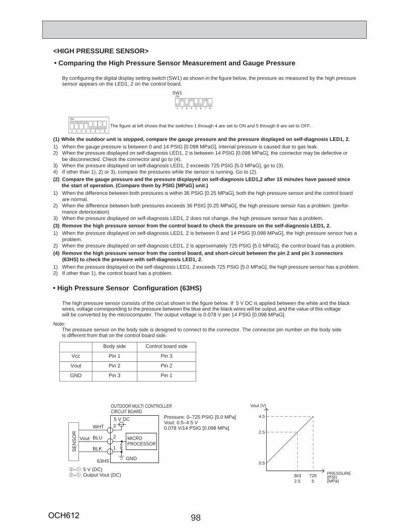
98
Comparing the High Pressure Sensor Measurement and Gauge Pressure
By configuring the digital display setting switch (SW1) as shown in the figure below, the pressure as measured by the high pressure sensor appears on the LED1, 2 on the control board.
(1) While the outdoor unit is stopped, compare the gauge pressure and the pressure displayed on self-diagnosis LED1, 2.1) When the gauge pressure is between 0 and 14 PSIG [0.098 MPaG], internal pressure is caused due to gas leak. 2) When the pressure displayed on self-diagnosis LED1, 2 is between 14 PSIG [0.098 MPaG], the connector may be defective or
be disconnected. Check the connector and go to (4). 3) When the pressure displayed on self-diagnosis LED1, 2 exceeds 725 PSIG [5.0 MPaG], go to (3).4) If other than 1), 2) or 3), compare the pressures while the sensor is running. Go to (2).(2) Compare the gauge pressure and the pressure displayed on self-diagnosis LED1,2 after 15 minutes have passed since the start of operation. (Compare them by PSIG [MPaG] unit.)1) When the difference between both pressures is within 36 PSIG [0.25 MPaG], both the high pressure sensor and the control board
are normal. 2) When the difference between both pressures exceeds 36 PSIG [0.25 MPaG], the high pressure sensor has a problem. (perfor-
mance deterioration) 3) When the pressure displayed on self-diagnosis LED1, 2 does not change, the high pressure sensor has a problem.(3) Remove the high pressure sensor from the control board to check the pressure on the self-diagnosis LED1, 2.1) When the pressure displayed on self-diagnosis LED1, 2 is between 0 and 14 PSIG [0.098 MPaG], the high pressure sensor has a
problem.2) When the pressure displayed on self-diagnosis LED1, 2 is approximately 725 PSIG [5.0 MPaG], the control board has a problem. (4) Remove the high pressure sensor from the control board, and short-circuit between the pin 2 and pin 3 connectors
(63HS) to check the pressure with self-diagnosis LED1, 2.1) When the pressure displayed on the self-diagnosis LED1, 2 exceeds 725 PSIG [5.0 MPaG], the high pressure sensor has a problem.2) If other than 1), the control board has a problem.
High Pressure Sensor Configuration (63HS)
The high pressure sensor consists of the circuit shown in the figure below. If 5 V DC is applied between the white and the black wires, voltage corresponding to the pressure between the blue and the black wires will be output, and the value of this voltage will be converted by the microcomputer. The output voltage is 0.078 V per 14 PSIG [0.098 MPaG].
The pressure sensor on the body side is designed to connect to the connector. The connector pin number on the body side is different from that on the control board side.
SW1ON
1 2 3 4 5 6 7 8
ON
1 2 3 4 5 6 7 8
The figure at left shows that the switches 1 through 4 are set to ON and 5 through 8 are set to OFF.
Body side Control board side
Vcc Pin 1 Pin 3
Vout Pin 2 Pin 2
GND Pin 3 Pin 1
<HIGH PRESSURE SENSOR>
Note:
3
2
1
WHT
BLU
BLKSE
NS
OR
5 V DC
GND63HS
Vout MICROPROCESSOR
OUTDOOR MULTI CONTROLLER CIRCUIT BOARD
3–1: 5 V (DC)2–1: Output Vout (DC)
Pressure: 0–725 PSIG [5.0 MPa]Vout: 0.5–4.5 V0.078 V/14 PSIG [0.098 MPa]
0.5
2.5 5
2.5
4.5
Vout (V)
PRESSURE (PSI)(MPa)
363 725
OCH612
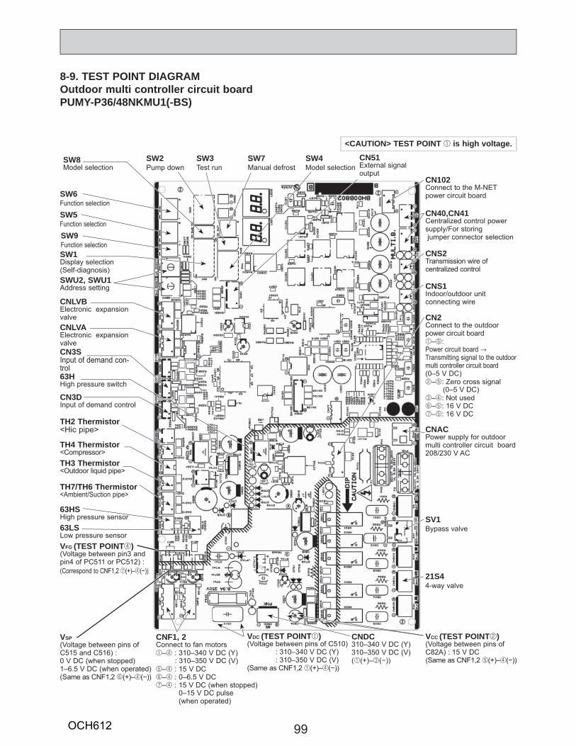
SW2Pump down
SW6Function selection
SW5Function selection
SW9Function selection
21S44-way valve
SV1Bypass valve
CNACPower supply for outdoor multi controller circuit board208/230 V AC
CNS1Indoor/outdoor unit connecting wire
CNS2Transmission wire of centralized control
CN40,CN41Centralized control power supply/For storing jumper connector selection
CN102Connect to the M-NET power circuit board
CN51External signaloutput
SW4Model selection
SW7Manual defrost
SW3Test run
CN2Connect to the outdoor power circuit board 1–5:Power circuit board → Transmitting signal to the outdoor multi controller circuit board (0–5 V DC)2–5: Zero cross signal (0–5 V DC)3–4: Not used 6–5: 16 V DC7–5: 16 V DC
CNDC310–340 V DC (Y)310–350 V DC (V)(1(+)–3(−))
VCC (TEST POINT2)(Voltage between pins of C82A) : 15 V DC(Same as CNF1,2 5(+)–4(−))
VSP (Voltage between pins of C515 and C516) : 0 V DC (when stopped)1–6.5 V DC (when operated)(Same as CNF1,2 6(+)–4(−))
CNF1, 2Connect to fan motors1–4 : 310–340 V DC (Y) : 310–350 V DC (V)5–4 : 15 V DC6–4 : 0–6.5 V DC7–4 : 15 V DC (when stopped) 0–15 V DC pulse (when operated)
VDC (TEST POINT1)(Voltage between pins of C510) : 310–340 V DC (Y) : 310–350 V DC (V)(Same as CNF1,2 1(+)–4(−))
VFG (TEST POINT4)(Voltage between pin3 and pin4 of PC511 or PC512) : (Correspond to CNF1,2 7(+)–4(−))
TH4 Thermistor<Compressor>
TH7/TH6 Thermistor<Ambient/Suction pipe>
63HSHigh pressure sensor
63HHigh pressure switch
TH3 Thermistor<Outdoor liquid pipe>
CN3DInput of demand control
CNLVAElectronic expansionvalve
SW1Display selection(Self-diagnosis)SWU2, SWU1Address setting
SW8Model selection
CN3SInput of demand con-trol
63LSLow pressure sensor
CNLVBElectronic expansionvalve
TH2 Thermistor<Hic pipe>
99
8-9. TEST POINT DIAGRAMOutdoor multi controller circuit boardPUMY-P36/48NKMU1(-BS)
<CAUTION> TEST POINT 1 is high voltage.
OCH612
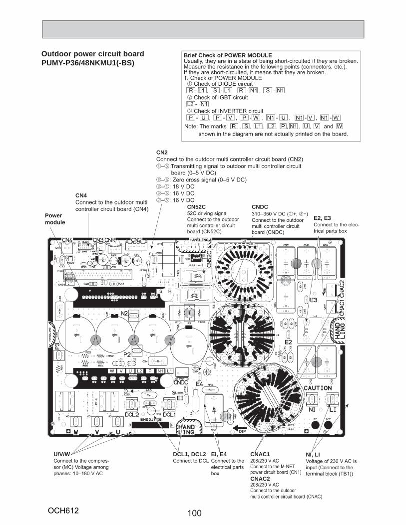
100
Outdoor power circuit boardPUMY-P36/48NKMU1(-BS)
CNAC1208/230 V ACConnect to the M-NET power circuit board (CN1)CNAC2208/230 V ACConnect to the outdoor multi controller circuit board
NI, LIVoltage of 230 V AC is input (Connect to the terminal block (TB1))
EI, E4Connect to the electrical parts box
DCL1, DCL2Connect to DCL
U/V/WConnect to the compres-sor (MC) Voltage among phases: 10–180 V AC
CNDC310–350 V DC (1+, 3−)Connect to the outdoor multi controller circuit board (CNDC)
E2, E3Connect to the elec-trical parts box
CN52C52C driving signalConnect to the outdoor multi controller circuit board (CN52C)
CN2Connect to the outdoor multi controller circuit board (CN2)1–5:Transmitting signal to outdoor multi controller circuit board (0–5 V DC)2–5: Zero cross signal (0–5 V DC)3–4: 18 V DC6–5: 16 V DC7–5: 16 V DC
CN4Connect to the outdoor multicontroller circuit board (CN4)
Brief Check of POWER MODULEUsually, they are in a state of being short-circuited if they are broken.Measure the resistance in the following points (connectors, etc.). If they are short-circuited, it means that they are broken.1. Check of POWER MODULE 1 Check of DIODE circuit R - L1 , S - L1 , R - N1 , S - N1 2 Check of IGBT circuit L2 - N1 3 Check of INVERTER circuit P - U , P - V , P - W , N1 - U , N1 - V , N1 - W
Power module
Note: The marks R , S , L1 , L2 , P , N1 , U , V and W shown in the diagram are not actually printed on the board.
S R
(CNAC)
W V U L2 P N1 L1
OCH612
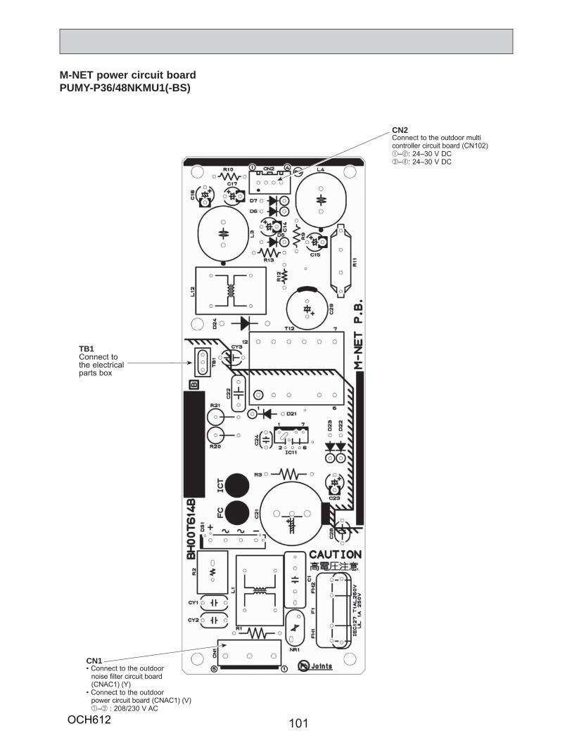
101
M-NET power circuit boardPUMY-P36/48NKMU1(-BS)
CN2Connect to the outdoor multi controller circuit board (CN102) 1–2: 24–30 V DC3–4: 24–30 V DC
CN1• Connect to the outdoor
noise filter circuit board (CNAC1) (Y)
• Connect to the outdoorpower circuit board (CNAC1) (V)1–3 : 208/230 V AC
TB1Connect to the electrical parts box
OCH612
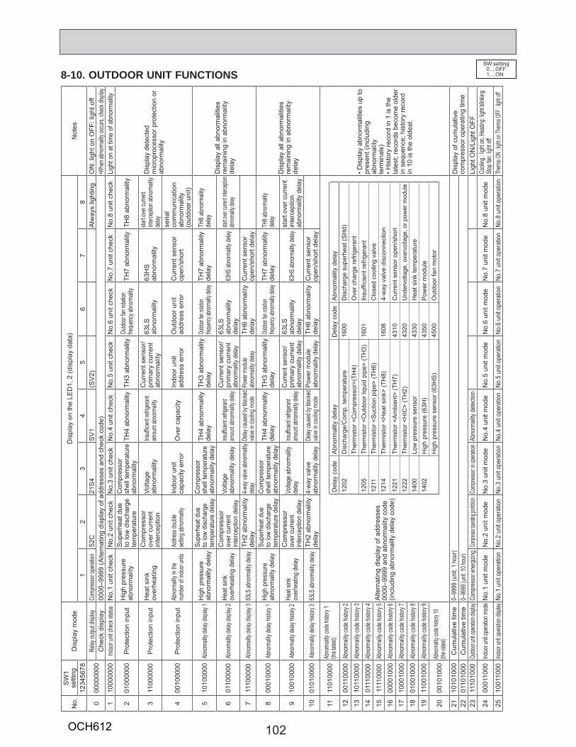
102
8-10. OUTDOOR UNIT FUNCTIONSSW:setting
0....OFF1....ON
No.
SW
1 se
tting
Dis
play
mod
eD
ispl
ay o
n th
e LE
D1,
2 (d
ispl
ay d
ata)
Not
es12
3456
781
23
45
67
8
000
0000
00Re
lay ou
tput d
isplay
Comp
resso
r ope
ration
52C
21S
4S
V1
(SV
2)A
lway
s lig
htin
gO
N: l
ight
on
OFF
: lig
ht o
ffC
heck
dis
play
0000
–999
9 (A
ltern
atin
g di
spla
y of
add
ress
es a
nd c
heck
cod
e)•W
hen a
bnorm
ality
occu
rs, ch
eck d
isplay
.1
1000
0000
Indoo
r unit
chec
k stat
usN
o.1
unit
chec
kN
o.2
unit
chec
kN
o.3
unit
chec
kN
o.4
unit
chec
kN
o.5
unit
chec
kN
o.6
unit
chec
kN
o.7
unit
chec
kN
o.8
unit
chec
kLi
ght o
n at
tim
e of
abn
orm
ality
201
0000
00P
rote
ctio
n in
put
Hig
h pr
essu
re
abno
rmal
ityS
uper
heat
due
to
low
dis
char
ge
tem
pera
ture
Com
pres
sor
shel
l tem
pera
ture
ab
norm
ality
TH4
abno
rmal
ityTH
3 ab
norm
ality
Outdo
or fan
rotat
ion
frequ
ency
abno
rmali
tyTH
7 ab
norm
ality
TH8
abno
rmal
ity
Dis
play
det
ecte
d m
icro
proc
esso
r pro
tect
ion
or
abno
rmal
ity3
1100
0000
Pro
tect
ion
inpu
tH
eat s
ink
over
heat
ing
Com
pres
sor
over
cur
rent
in
terc
eptio
nVo
ltage
ab
norm
ality
Insuffi
cien
t refrig
erant
amou
nt ab
norm
ality
Cur
rent
sen
sor/
prim
ary
curr
ent
abno
rmal
ity63
LSab
norm
ality
63H
S
abno
rmal
itysta
rt ove
r curr
ent
interc
eptio
n abn
ormali
ty de
lay
400
1000
00P
rote
ctio
n in
put
Abno
rmali
ty in
the
numb
er of
indoo
r unit
sAd
dress
doub
lese
tting a
bnorm
ality
Indo
or u
nit
capa
city
err
orO
ver c
apac
ityIn
door
uni
t ad
dres
s er
ror
Out
door
uni
t ad
dres
s er
ror
Cur
rent
sen
sor
open
/sho
rt
seria
l co
mm
unic
atio
n ab
norm
ality
(o
utdo
or u
nit)
510
1000
00Ab
norm
ality
delay
disp
lay 1
Hig
h pr
essu
re
abno
rmal
ity d
elay
Supe
rhea
t due
to
low
disc
harg
e te
mpe
ratu
re d
elay
Com
pres
sor
shel
l tem
pera
ture
ab
norm
ality
del
ayTH
4 ab
norm
ality
de
lay
TH3
abno
rmal
ity
dela
yOu
tdoor
fan ro
tation
freque
ncy ab
norma
lity de
layTH
7 ab
norm
ality
de
lay
TH8
abno
rmali
tyde
layD
ispl
ay a
ll ab
norm
aliti
es
rem
aini
ng in
abn
orm
ality
de
lay
601
1000
00Ab
norm
ality
delay
disp
lay 2
Heat
sin
k ov
erhe
atin
g de
lay
Com
pres
sor
over
cur
rent
in
terc
eptio
n de
lay
Volta
ge
abno
rmal
ity d
elay
Insuffi
cient
refrig
erant
amou
nt ab
norm
ality d
elay
Cur
rent
sen
sor/
prim
ary
curr
ent
abno
rmali
ty de
lay
63LS
abno
rmal
ity
dela
y63
HS ab
norm
ality
delay
start o
ver cu
rrent i
nterce
ption
abnorm
ality d
elay
711
1000
00Ab
norm
ality
delay
disp
lay 3
63LS
abno
rmali
ty de
layTH
2 ab
norm
ality
de
lay
4-way
valve
abno
rmali
ty de
layDe
lay ca
used
by bl
ocke
d va
lve in
cooli
ng m
ode
Powe
r mod
ule
abno
rmali
ty de
layTH
6 ab
norm
ality
de
lay
Cur
rent
sen
sor
open
/sho
rt de
lay
800
0100
00Ab
norm
ality
delay
histo
ry 1
High
pre
ssur
e ab
norm
ality
del
aySu
perh
eat d
ue
to lo
w di
scha
rge
tem
pera
ture
del
ay
Com
pres
sor
shel
l tem
pera
ture
ab
norm
ality
del
ayTH
4 ab
norm
ality
de
lay
TH3
abno
rmal
ity
dela
yOu
tdoor
fan ro
tation
freque
ncy ab
norma
lity de
layTH
7 ab
norm
ality
de
lay
TH8 a
bnorm
ality
delay
Dis
play
all
abno
rmal
ities
re
mai
ning
in a
bnor
mal
ity
dela
y9
1001
0000
Abno
rmali
ty de
lay hi
story
2He
at si
nk
over
heat
ing d
elay
Com
pres
sor
over
cur
rent
in
terc
eptio
n de
lay
Volta
ge a
bnor
mali
ty de
layIns
uffi cie
nt ref
rigera
nt am
ount
abno
rmalit
y dela
yCu
rrent
sen
sor/
prim
ary
curr
ent
abno
rmal
ity d
elay
63LS
abno
rmal
ity
dela
y63
HS ab
norm
ality
delay
star
t ove
r cur
rent
in
terc
eptio
n ab
norm
ality
del
ay
1001
0100
00Ab
norm
ality
delay
histo
ry 3
63LS
abno
rmali
ty de
layTH
2 ab
norm
ality
de
lay
4-wa
y va
lve
abno
rmal
ity d
elay
Delay
caus
ed by
bloc
ked
valve
in co
oling
mod
ePo
wer m
odul
e ab
norm
ality
del
ayTH
6 ab
norm
ality
de
lay
Cur
rent
sen
sor
open
/sho
rt de
lay
1111
0100
00Ab
norm
ality
code
histo
ry 1
(the l
atest)
Alte
rnat
ing
disp
lay
of a
ddre
sses
0000
–999
9 an
d ab
norm
ality
cod
e(in
clud
ing
abno
rmal
ity d
elay
cod
e)
• Dis
play
abn
orm
aliti
es u
p to
pres
ent (
incl
udin
g ab
norm
ality
term
inal
s)• H
isto
ry re
cord
in 1
is th
ela
test
; rec
ords
bec
ome
olde
rin
seq
uenc
e; h
isto
ry re
cord
in 1
0 is
the
olde
st.
1200
1100
00Ab
norm
ality
code
histo
ry 2
1310
1100
00Ab
norm
ality
code
histo
ry 3
1401
1100
00Ab
norm
ality
code
histo
ry 4
1511
1100
00Ab
norm
ality
code
histo
ry 5
1600
0010
00Ab
norm
ality
code
histo
ry 6
1710
0010
00Ab
norm
ality
code
histo
ry 7
1801
0010
00Ab
norm
ality
code
histo
ry 8
1911
0010
00Ab
norm
ality
code
histo
ry 9
2000
1010
00Ab
norm
ality c
ode h
istory
10
(the o
ldest)
2110
1010
00C
umul
ativ
e tim
e0–
9999
(unit
: 1 h
our)
Dis
play
of c
umul
ativ
e co
mpr
esso
r ope
ratin
g tim
e22
0110
1000
Cum
ulat
ive
time
0–99
99 (u
nit: 1
0 hou
r)23
1110
1000
Outdo
or un
it ope
ration
displa
yCo
mpres
sor e
nergi
zing
Compre
ssor op
erating
prohib
itionCo
mpres
sor in
opera
tion
Abno
rmali
ty de
tectio
nLi
ght O
N/L
ight
OFF
2400
0110
00Ind
oor u
nit op
eratio
n mod
eN
o.1
unit
mod
eN
o.2
unit
mod
eN
o.3
unit
mod
eN
o.4
unit
mod
eN
o.5
unit
mod
eN
o.6
unit
mod
eN
o.7
unit
mod
eN
o.8
unit
mod
eCo
oling
: ligh
t on,
Heati
ng: li
ght b
linkin
gSt
op fa
n: lig
ht off
2510
0110
00Ind
oor u
nit op
eratio
n disp
layNo
.1 u
nit o
pera
tion
No.2
unit
ope
ratio
nNo
.3 u
nit o
pera
tion
No.4
unit
ope
ratio
nNo
.5 u
nit o
pera
tion
No.6
unit
ope
ratio
nNo
.7 u
nit o
pera
tion
No.8
unit
ope
ratio
nTh
ermo O
N : lig
ht on
Therm
o OFF
: ligh
t off
Del
ay c
ode
Abn
orm
ality
del
ayD
elay
cod
eA
bnor
mal
ity d
elay
1202
Dis
char
ge/C
omp.
tem
pera
ture
16
00D
isch
arge
sup
erhe
at (S
Hd)
Th
erm
isto
r <C
ompr
esso
r>(T
H4)
O
ver c
harg
e re
frige
rant
12
05Th
erm
isto
r <O
utdo
or li
quid
pip
e> (T
H3)
16
01In
suffi
cien
t ref
riger
ant
1211
Ther
mis
tor <
Suc
tion
pipe
> (T
H6)
C
lose
d co
olin
g va
lve
1214
Ther
mis
tor <
Hea
t sin
k> (T
H8)
16
084-
way
val
ve d
isco
nnec
tion
1221
Ther
mis
tor <
Am
bien
t> (T
H7)
43
10C
urre
nt s
enso
r ope
n/sh
ort
1222
Ther
mis
tor <
HIC
> (T
H2)
4320
Und
ervo
ltage
, ove
rvol
tage
, or p
ower
mod
ule
1400
Low
pre
ssur
e se
nsor
43
30H
eat s
ink
tem
pera
ture
14
02H
igh
pres
sure
(63H
)43
50P
ower
mod
ule
Hig
h pr
essu
re s
enso
r (63
HS
) 45
00O
utdo
or fa
n m
otor
OCH612
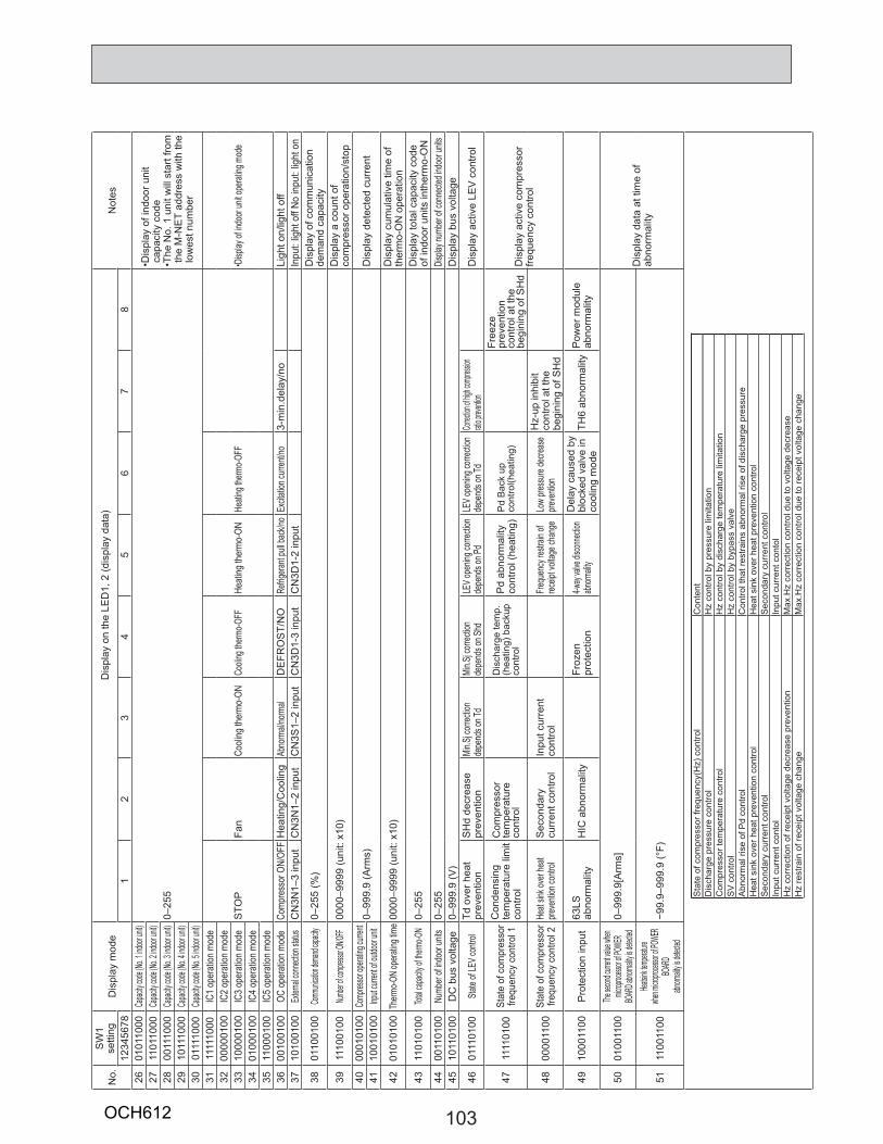
103
No.
SW
1 se
tting
Dis
play
mod
eD
ispl
ay o
n th
e LE
D1,
2 (d
ispl
ay d
ata)
Not
es12
3456
781
23
45
67
826
0101
1000
Capac
ity cod
e (No. 1
indoor
unit)
0–25
5
•Dis
play
of i
ndoo
r uni
tca
paci
ty c
ode
•The
No.
1 u
nit w
ill s
tart
from
th
e M
-NE
T ad
dres
s w
ith th
e lo
wes
t num
ber
2711
0110
00Ca
pacity
code (N
o. 2 ind
oor un
it)28
0011
1000
Capac
ity cod
e (No. 3
indoor
unit)
2910
1110
00Ca
pacity
code (N
o. 4 ind
oor un
it)30
0111
1000
Capac
ity cod
e (No. 5
indoor
unit)
3111
1110
00IC
1 op
erat
ion m
ode
STO
PFa
nCo
oling
ther
mo-
ONCo
oling
therm
o-OFF
Heat
ing th
erm
o-ON
Heati
ng th
ermo-O
FF•D
isplay
of in
door
unit o
perat
ing m
ode
3200
0001
00IC
2 op
erat
ion m
ode
3310
0001
00IC
3 op
erat
ion m
ode
3401
0001
00IC
4 op
erat
ion m
ode
3511
0001
00IC
5 op
erat
ion m
ode
3600
1001
00OC
oper
ation
mod
eCo
mpre
ssor
ON/
OFF
Hea
ting/
Coo
ling
Abno
rmal/
norm
alD
EFR
OS
T/N
ORe
frigera
nt pu
ll bac
k/no
Excit
ation
curre
nt/no
3-m
in.d
elay
/no
Ligh
t on/
light
off
3710
1001
00Ex
terna
l conn
ection
status
CN
3N1–
3 in
put
CN
3N1–
2 in
put
CN
3S1–
2 in
put
CN
3D1-
3 in
put
CN
3D1-
2 in
put
Inpu
t: lig
ht o
ff No
inpu
t: lig
ht o
n
3801
1001
00Com
munica
tion de
mand
capacit
y0–
255
(%)
Dis
play
of c
omm
unic
atio
n de
man
d ca
paci
ty
3911
1001
00Num
ber of
compre
ssor O
N/OFF
0000
–999
9 (u
nit:
x10)
Dis
play
a c
ount
of
com
pres
sor o
pera
tion/
stop
4000
0101
00Co
mpres
sor op
erating
curre
nt0–
999.
9 (A
rms)
Dis
play
det
ecte
d cu
rren
t41
1001
0100
Input
curren
t of o
utdoo
r unit
4201
0101
00Th
ermo-O
N op
eratin
g tim
e00
00–9
999
(uni
t: x1
0)D
ispl
ay c
umul
ativ
e tim
e of
th
erm
o-O
N o
pera
tion
4311
0101
00Tot
al cap
acity o
f therm
o-ON
0–25
5D
ispl
ay to
tal c
apac
ity c
ode
of in
door
uni
ts in
ther
mo-
ON
4400
1101
00Nu
mber
of ind
oor u
nits
0–25
5Dis
play n
umbe
r of c
onne
cted i
ndoo
r unit
s45
1011
0100
DC
bus
vol
tage
0–99
9.9
(V)
Dis
play
bus
vol
tage
4601
1101
00Sta
te of
LEV c
ontro
lTd
ove
r hea
tpr
even
tion
SH
d de
crea
sepr
even
tion
Min.S
j corr
ectio
nde
pend
s on T
dMi
n.Sj c
orrec
tion
depe
nds o
n Shd
LEV o
penin
g corr
ectio
nde
pend
s on P
dLE
V ope
ning c
orrec
tion
depe
nds o
n Td
Correc
tion of
high c
ompre
ssion
ratio p
revent
ionD
ispl
ay a
ctiv
e LE
V c
ontro
l
4711
1101
00St
ate
of c
ompr
esso
rfre
quen
cy c
ontro
l 1C
onde
nsin
g te
mpe
ratu
re li
mit
cont
rol
Com
pres
sor
tem
pera
ture
co
ntro
l
Dis
char
ge te
mp.
(h
eatin
g) b
acku
p co
ntro
lP
d ab
norm
ality
cont
rol (
heat
ing)
Pd
Bac
k up
co
ntro
l(hea
ting)
Free
ze
prev
entio
n co
ntro
l at t
he
begi
ning
of S
Hd
Dis
play
act
ive
com
pres
sor
frequ
ency
con
trol
4800
0011
00St
ate
of c
ompr
esso
rfre
quen
cy c
ontro
l 2He
at sin
k ove
r hea
t pre
venti
on co
ntrol
Sec
onda
rycu
rren
t con
trol
Inpu
t cur
rent
cont
rol
Frequ
ency
restr
ain of
rec
eipt v
oltag
e cha
nge
Low
press
ure de
creas
e pre
venti
onH
z-up
inhi
bit
cont
rol a
t the
be
gini
ng o
f SH
d
4910
0011
00P
rote
ctio
n in
put
63LS
ab
norm
ality
HIC
abn
orm
ality
Froz
en
prot
ectio
n4-w
ay val
ve dis
conne
ction
abno
rmalit
yD
elay
cau
sed
by
bloc
ked
valv
e in
co
olin
g m
ode
TH6
abno
rmal
ityP
ower
mod
ule
abno
rmal
ity
5001
0011
00The
secon
d curre
nt valu
e when
microp
rocess
or of PO
WER
BOAR
D abno
rmality
is dete
cted
0–99
9.9[
Arm
s]
Dis
play
dat
a at
tim
e of
ab
norm
ality
5111
0011
00Hea
tsink te
mpera
turewhe
n micro
proces
sor of
POWE
R BO
ARD
abnorm
ality is d
etecte
d−9
9.9–
999.
9 (°
F)
Sta
te o
f com
pres
sor f
requ
ency
(Hz)
con
trol
Con
tent
Dis
char
ge p
ress
ure
cont
rol
Hz
cont
rol b
y pr
essu
re li
mita
tion
Com
pres
sor t
empe
ratu
re c
ontro
lH
z co
ntro
l by
disc
harg
e te
mpe
ratu
re li
mita
tion
SV
con
trol
Hz
cont
rol b
y by
pass
val
veA
bnor
mal
rise
of P
d co
ntro
lC
ontro
l tha
t res
train
s ab
norm
al ri
se o
f dis
char
ge p
ress
ure
Hea
t sin
k ov
er h
eat p
reve
ntio
n co
ntro
lH
eat s
ink
over
hea
t pre
vent
ion
cont
rol
Sec
onda
ry c
urre
nt c
ontro
lS
econ
dary
cur
rent
con
trol
Inpu
t cur
rent
con
tol
Inpu
t cur
rent
con
tol
Hz
corr
ectio
n of
rece
ipt v
olta
ge d
ecre
ase
prev
entio
nM
ax.H
z co
rrec
tion
cont
rol d
ue to
vol
tage
dec
reas
eH
z re
stra
in o
f rec
eipt
vol
tage
cha
nge
Max
.Hz
corr
ectio
n co
ntro
l due
to re
ceip
t vol
tage
cha
nge
OCH612
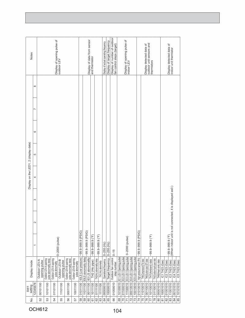
104
No.
SW
1 se
tting
Dis
play
mod
eD
ispl
ay o
n th
e LE
D1,
2 (d
ispl
ay d
ata)
Not
es12
3456
781
23
45
67
8
5200
1011
00O
utdo
or L
EV-
A op
enin
g pu
lse
0–20
00 (p
ulse
)D
ispl
ay o
f ope
ning
pul
se o
f ou
tdoo
r LE
V
5310
1011
00Ou
tdoor
LEV-A
open
ing
pulse
abno
rmali
ty de
lay
5401
1011
00Ou
tdoor
LEV-A
open
ing
pulse
abno
rmali
ty
5511
1011
00O
utdo
or L
EV-
B
open
ing
puls
e
5600
0111
00Ou
tdoor
LEV-B
open
ing
pulse
abno
rmali
ty de
lay
5710
0111
00Ou
tdoor
LEV-B
open
ing
pulse
abno
rmali
ty58
0101
1100
63LS
(Low
pre
ssur
e)−9
9.9–
999.
9 (P
SIG
)
Dis
play
of d
ata
from
sen
sor
and
ther
mis
tor
5911
0111
0063
LS ab
norm
ality
delay
−99.
9–99
9.9
(PS
IG)
6000
1111
0063
LS
abn
orm
ality
61
1011
1100
TH2
(Hic
pip
e)−9
9.9–
999.
9 (°
F)62
0111
1100
TH2(H
ic) ab
norm
ality d
elay
−99.
9–99
9.9
(°F)
6311
1111
00TH
2 (Hic
) abn
ormalit
y64
0000
0010
Opera
tiona
l freq
uenc
y0–
255
(Hz)
Displa
y of a
ctual
opera
ting f
reque
ncy
6510
0000
10Ta
rget
freq
uenc
y0–
255
(Hz)
Dis
play
of t
arge
t fre
quen
cy
6601
0000
10O
utdo
or fa
n co
ntro
l st
ep n
umbe
r0–
15D
ispl
ay o
f num
ber o
f out
door
fa
n co
ntro
l ste
ps (t
arge
t)69
1010
0010
IC1 L
EV O
penin
g puls
e
0–2
000
(pul
se)
Dis
play
of o
peni
ng p
ulse
of
indo
or L
EV
7001
1000
10IC
2 LEV
Ope
ning p
ulse
7111
1000
10IC
3 LEV
Ope
ning p
ulse
7200
0100
10IC
4 LEV
Ope
ning p
ulse
7310
0100
10IC
5 LEV
Ope
ning p
ulse
7401
0100
10Hig
h pres
sure
sens
or (Pd
) −9
9.9–
999.
9 (P
SIG
)
Dis
play
det
ecte
d da
ta o
f ou
tdoo
r uni
t sen
sors
and
th
erm
isto
rs
7511
0100
10TH
4(Com
presso
r)(Td)
data
−99.
9–99
9.9
(°F)
7600
1100
10TH
6(Suct
ion pip
e) (ET
) data
7710
1100
10TH
7(Am
bient
) dat
a78
0111
0010
TH3(O
utdoor
liquid
pipe) d
ata80
0000
1010
TH8(H
eat s
ink) d
ata81
1000
1010
IC1
TH23
(Gas
)
−99.
9–99
9.9
(°F)
(W
hen
indo
or u
nit i
s no
t con
nect
ed, i
t is
disp
laye
d as
0.)
Dis
play
det
ecte
d da
ta o
f in
door
uni
t the
rmis
tor
8201
0010
10IC
2 TH
23 (G
as)
8311
0010
10IC
3 TH
23 (G
as)
8400
1010
10IC
4 TH
23 (G
as)
8510
1010
10IC
5 TH
23 (G
as)
OCH612
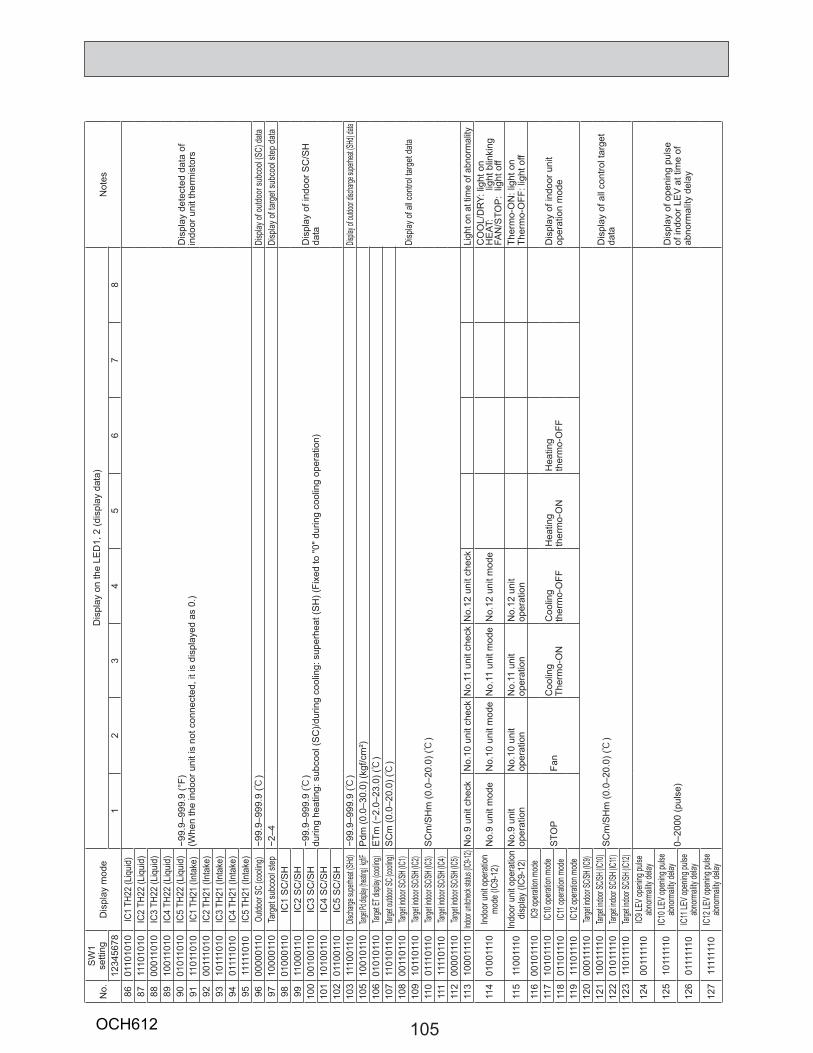
105
No.
SW
1 se
tting
Dis
play
mod
eD
ispl
ay o
n th
e LE
D1,
2 (d
ispl
ay d
ata)
Not
es12
3456
781
23
45
67
886
0110
1010
IC1
TH22
(Liq
uid)
−99.
9–99
9.9
(°F)
(Whe
n th
e in
door
uni
t is
not c
onne
cted
, it i
s di
spla
yed
as 0
.)D
ispl
ay d
etec
ted
data
of
indo
or u
nit t
herm
isto
rs
8711
1010
10IC
2 TH
22 (L
iqui
d)88
0001
1010
IC3
TH22
(Liq
uid)
8910
0110
10IC
4 TH
22 (L
iqui
d)90
0101
1010
IC5
TH22
(Liq
uid)
9111
0110
10IC
1 TH
21 (I
ntak
e)92
0011
1010
IC2
TH21
(Int
ake)
9310
1110
10IC
3 TH
21 (I
ntak
e)94
0111
1010
IC4
TH21
(Int
ake)
9511
1110
10IC
5 TH
21 (I
ntak
e)96
0000
0110
Outdo
or SC
(coo
ling)
−99.
9–99
9.9
(:)
Disp
lay of
outdo
or su
bcoo
l (SC)
data
9710
0001
10Ta
rget
subc
ool s
tep
−2–4
Disp
lay o
f tar
get s
ubco
ol ste
p da
ta98
0100
0110
IC1
SC
/SH
−99.
9–99
9.9
(:)
durin
g he
atin
g: s
ubco
ol (S
C)/d
urin
g co
olin
g: s
uper
heat
(SH
) (Fi
xed
to "0
" dur
ing
cool
ing
oper
atio
n)D
ispl
ay o
f ind
oor S
C/S
H
data
9911
0001
10IC
2 S
C/S
H
100
0010
0110
IC3
SC
/SH
10
110
1001
10IC
4 S
C/S
H
102
0110
0110
IC5
SC
/SH
10
311
1001
10Dis
charge
supe
rheat
(SHd)
−99.
9–99
9.9
(:)
Displa
y of ou
tdoor d
ischar
ge sup
erheat
(SHd
) data
105
1001
0110
Target
Pd dis
play (h
eating
) kgf/F
P
dm (0
.0–3
0.0)
(kgf
/cm
²)
Disp
lay o
f all c
ontro
l targ
et d
ata
106
0101
0110
Targe
t ET d
isplay
(coo
ling)
ETm
(−2.
0–23
.0) (:
)10
711
0101
10Tar
get o
utdoo
r SC (
cooling
)S
Cm
(0.0
–20.
0) (:
)10
800
1101
10Tar
get in
door
SC/SH
(IC1)
SC
m/S
Hm
(0.0
–20.
0) (:
)10
910
1101
10Tar
get in
door
SC/SH
(IC2)
110
0111
0110
Targe
t indo
or SC
/SH (IC
3)11
111
1101
10Tar
get in
door
SC/SH
(IC4)
112
0000
1110
Targe
t indo
or SC
/SH (IC
5)11
310
0011
10Ind
oor un
itcheck
status
(IC9-1
2)N
o.9
unit
chec
kN
o.10
uni
t che
ckN
o.11
uni
t che
ckN
o.12
uni
t che
ckLi
ght o
n at
tim
e of
abn
orm
ality
114
0100
1110
Indo
or u
nit o
pera
tion
mod
e (IC
9-12
)N
o.9
unit
mod
eN
o.10
uni
t mod
eN
o.11
uni
t mod
eN
o.12
uni
t mod
eC
OO
L/D
RY:
ligh
t on
H
EAT
:
light
blin
king
FAN
/STO
P:
light
off
115
1100
1110
Indo
or u
nit o
pera
tion
disp
lay
(IC9-
12)
No.
9 un
it op
erat
ion
No.
10 u
nit
oper
atio
nN
o.11
uni
t op
erat
ion
No.
12 u
nit
oper
atio
nTh
erm
o-O
N: l
ight
on
Th
erm
o-O
FF: l
ight
off
116
0010
1110
IC9 o
perat
ion m
ode
STO
PFa
nC
oolin
g Th
erm
o-O
NC
oolin
gth
erm
o-O
FFH
eatin
g th
erm
o-O
NH
eatin
gth
erm
o-O
FFD
ispl
ay o
f ind
oor u
nit
oper
atio
n m
ode
117
1010
1110
IC10
opera
tion m
ode
118
0110
1110
IC11
opera
tion m
ode
119
1110
1110
IC12
opera
tion m
ode
120
0001
1110
Targe
t indo
or SC
/SH (IC
9)
SC
m/S
Hm
(0.0
–20.
0) (:
)D
ispl
ay o
f all
cont
rol t
arge
t da
ta12
110
0111
10Tar
get in
door
SC/SH
(IC10
)12
201
0111
10Tar
get in
door
SC/SH
(IC11)
123
1101
1110
Targe
t indo
or SC
/SH (IC
12)
124
0011
1110
IC9 L
EV op
ening
pulse
ab
norm
ality
delay
0–20
00 (p
ulse
)D
ispl
ay o
f ope
ning
pul
se
of in
door
LE
V a
t tim
e of
ab
norm
ality
del
ay
125
1011
1110
IC10
LEV o
penin
g puls
e ab
norm
ality
delay
126
0111
1110
IC11
LEV o
penin
g puls
e ab
norm
ality
delay
127
1111
1110
IC12
LEV o
penin
g puls
e ab
norm
ality
delay
OCH612
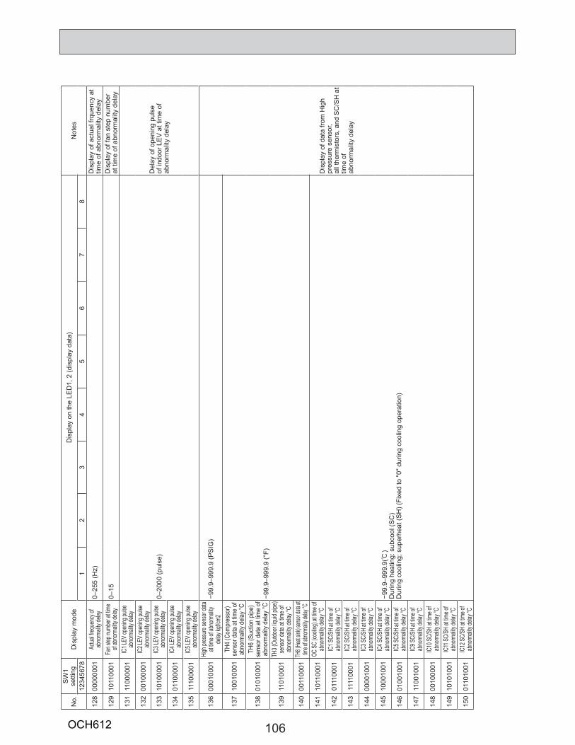
106
No.
SW
1 se
tting
Dis
play
mod
eD
ispl
ay o
n th
e LE
D1,
2 (d
ispl
ay d
ata)
Not
es12
3456
781
23
45
67
8
128
0000
0001
Actua
l freq
uenc
y of
abno
rmali
ty de
lay0–
255
(Hz)
Dis
play
of a
ctua
l frq
uenc
y at
tim
e of
abn
orm
ality
del
ay
129
1011
0001
Fan s
tep nu
mber
at tim
e of
abno
rmali
ty de
lay0–
15D
ispl
ay o
f fan
ste
p nu
mbe
r at
tim
e of
abn
orm
ality
del
ay
131
1100
0001
IC1 L
EV op
ening
pulse
ab
norm
ality
delay
0–20
00 (p
ulse
)D
elay
of o
peni
ng p
ulse
of
indo
or L
EV
at t
ime
of
abno
rmal
ity d
elay
132
0010
0001
IC2 L
EV op
ening
pulse
ab
norm
ality
delay
133
1010
0001
IC3 L
EV op
ening
pulse
ab
norm
ality
delay
134
0110
0001
IC4 L
EV op
ening
pulse
ab
norm
ality
delay
135
1110
0001
IC5 L
EV op
ening
pulse
ab
norm
ality
delay
136
0001
0001
High p
ressu
re se
nsor
data
at tim
e of a
bnorm
ality
delay
kgf/c
m2−9
9.9–
999.
9 (P
SIG
)
Dis
play
of d
ata
from
Hig
h pr
essu
re s
enso
r,al
l the
rmis
tors
, and
SC
/SH
at
time
ofab
norm
ality
del
ay
137
1001
0001
TH4
(Com
pres
sor)
sens
or d
ata
at tim
e of
ab
norm
ality
delay
°C
−99.
9–99
9.9
(°F)
138
0101
0001
TH6
(Suc
tion
pipe
) se
nsor
dat
a at
tim
e of
ab
norm
ality
del
ay °C
139
1101
0001
TH3 (
Outdo
or liq
uid pi
pe)
sens
or da
ta at
time o
f ab
norm
ality
delay
°C
140
0011
0001
TH8 (
Heat
sink)
sensor
data
at tim
e of a
bnorm
ality d
elay °
C
141
1011
0001
OC SC
(coo
ling)
at tim
e of
abno
rmali
ty de
lay °C
−99.
9–99
9.9(:
)D
urin
g he
atin
g: s
ubco
ol (S
C)
Dur
ing
cool
ing;
sup
erhe
at (S
H) (
Fixe
d to
"0" d
urin
g co
olin
g op
erat
ion)
142
0111
0001
IC1 S
C/SH
at tim
e of
abno
rmali
ty de
lay °C
143
1111
0001
IC2 S
C/SH
at tim
e of
abno
rmali
ty de
lay °C
144
0000
1001
IC3 S
C/SH
at tim
e of
abno
rmali
ty de
lay °C
145
1000
1001
IC4 S
C/SH
at tim
e of
abno
rmali
ty de
lay °C
146
0100
1001
IC5 S
C/SH
at tim
e of
abno
rmali
ty de
lay °C
147
1100
1001
IC9 S
C/SH
at tim
e of
abno
rmali
ty de
lay °C
148
0010
0001
IC10
SC/SH
at tim
e of
abno
rmali
ty de
lay °C
149
1010
1001
IC11
SC/SH
at tim
e of
abno
rmali
ty de
lay °C
150
0110
1001
IC12
SC/SH
at tim
e of
abno
rmali
ty de
lay °C
OCH612
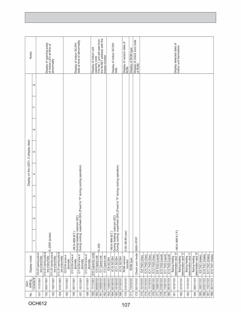
107
No.
SW
1 se
tting
Dis
play
mod
eD
ispl
ay o
n th
e LE
D1,
2 (d
ispl
ay d
ata)
Not
es12
3456
781
23
45
67
8
151
1110
1001
IC9 L
EV op
ening
pulse
at
time o
f abn
ormali
ty
0–20
00 (p
ulse
)D
ispl
ay o
f ope
ning
pul
se
of in
door
LE
V a
t tim
e of
ab
norm
ality
152
0001
1001
IC10
LEV o
penin
g puls
e at
time o
f abn
ormali
ty
153
1001
1001
IC11
LEV o
penin
g puls
e at
time o
f abn
ormali
ty
154
0101
1001
IC12
LEV o
penin
g puls
e at
time o
f abn
ormali
ty
155
1101
1001
IC9 S
C/SH
at tim
e of
abno
rmali
ty
−99.
9–99
9.9(:
)D
urin
g he
atin
g: s
ubco
ol (S
C)
Dur
ing
cool
ing;
sup
erhe
at (S
H) (
Fixe
d to
"0" d
urin
g co
olin
g op
erat
ion)
Dis
play
of i
ndoo
r SC
/SH
da
ta a
t tim
e of
abn
orm
ality
156
0011
1001
IC10
SC/SH
at tim
e of
abno
rmali
ty
157
1011
1001
IC11
SC/SH
at tim
e of
abno
rmali
ty
158
0111
1001
IC12
SC/SH
at tim
e of
abno
rmali
ty15
911
1110
01IC
9 C
apac
ity c
ode
0–25
5
Dis
play
of i
ndoo
r uni
t ca
paci
ty c
ode
The
No.
1 un
it w
ill s
tart
from
th
e M
-NE
T ad
dres
s w
ith th
e lo
wes
t num
ber
160
0000
0101
IC10
Cap
acity
code
161
1000
0101
IC11
Cap
acity
code
162
0100
0101
IC12
Cap
acity
code
163
1100
0101
IC9
SC
/SH
−99.
9–99
9.9(:
)D
urin
g he
atin
g: s
ubco
ol (S
C)
Dur
ing
cool
ing;
sup
erhe
at (S
H) (
Fixe
d to
"0" d
urin
g co
olin
g op
erat
ion)
Dis
play
of i
ndoo
r SC
/SH
da
ta
164
0010
0101
IC10
SC
/SH
165
1010
0101
IC11
SC
/SH
166
0110
0101
IC12
SC
/SH
170
0101
0101
RO
M v
ersi
on
mon
itor
0.00
–99.
99 (v
er)
Dis
play
of v
ersi
on d
ata
of
RO
M17
111
0101
01R
OM
type
Dis
play
of R
OM
type
172
0011
0101
Che
ck s
um m
ode
0000
–FFF
FD
ispl
ay o
f che
ck s
um c
ode
of R
OM
173
1011
0101
IC9
TH23
(Gas
)
−99.
9–99
9.9
(°F)
D
ispl
ay d
etec
ted
data
of
indo
or u
nit t
herm
isto
rs
174
0111
0101
IC10
TH2
3 (G
as)
175
1111
0101
IC11
TH2
3 (G
as)
176
0000
1101
IC12
TH2
3 (G
as)
177
1000
1101
IC9
TH22
(Liq
uid)
178
0100
1101
IC10
TH2
2 (L
iquid)
179
1100
1101
IC11
TH2
2 (L
iquid)
180
0010
1101
IC12
TH2
2 (L
iquid)
181
1010
1101
Back
up h
eatin
gde
term
inatio
n va
lue "a
"
182
0110
1101
Back
up h
eatin
gde
term
inatio
n va
lue "b
"
183
1110
1101
Back
up h
eatin
gde
term
inatio
n va
lue "c
"
184
0001
1101
Back
up h
eatin
gde
term
inatio
n va
lue "d
"18
510
0111
01IC
9 TH
21 (I
ntak
e)18
601
0111
01IC
10 T
H21
(Inta
ke)
187
1101
1101
IC11
TH2
1 (In
take
)18
800
1111
01IC
12 T
H21
(Inta
ke)
OCH612
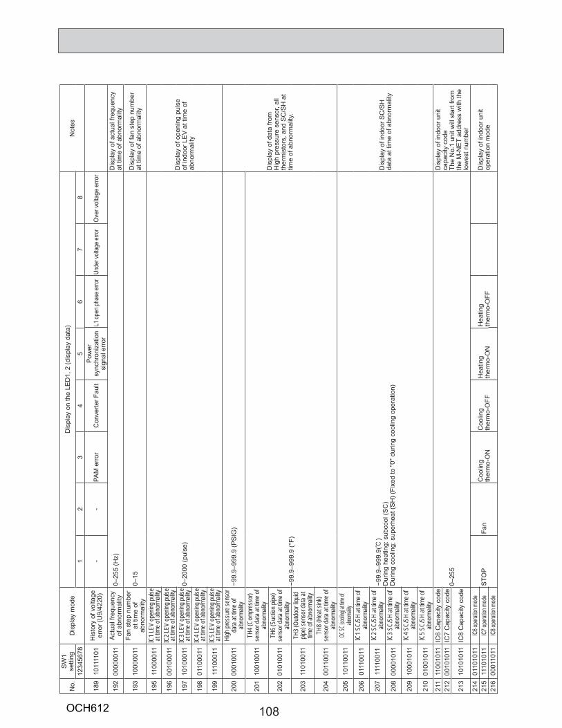
108
No.
SW
1 se
tting
Dis
play
mod
eD
ispl
ay o
n th
e LE
D1,
2 (d
ispl
ay d
ata)
Not
es12
3456
781
23
45
67
8
189
1011
1101
His
tory
of v
olta
ge
erro
r (U
9/42
20)
--
PAM
err
orC
onve
rter F
ault
Pow
er
sync
hron
izat
ion
sign
al e
rror
L1 o
pen
phas
e er
ror
Unde
r volt
age
erro
rO
ver v
olta
ge e
rror
192
0000
0011
Act
ual f
requ
ency
of
abn
orm
ality
0–25
5 (H
z)D
ispl
ay o
f act
ual f
requ
ency
at
tim
e of
abn
orm
ality
193
1000
0011
Fan
step
num
ber
at ti
me
of
abno
rmal
ity0–
15D
ispl
ay o
f fan
ste
p nu
mbe
r at
tim
e of
abn
orm
ality
195
1100
0011
IC1 L
EV op
ening
pulse
at
time o
f abn
orma
lity
0–20
00 (p
ulse
)D
ispl
ay o
f ope
ning
pul
se
of in
door
LE
V a
t tim
e of
ab
norm
ality
196
0010
0011
IC2 L
EV op
ening
pulse
at
time o
f abn
orma
lity
197
1010
0011
IC3 L
EV op
ening
pulse
at
time o
f abn
orma
lity
198
0110
0011
IC4 L
EV op
ening
pulse
at
time o
f abn
orma
lity
199
1110
0011
IC5 L
EV op
ening
pulse
at
time o
f abn
orma
lity
200
0001
0011
High
pres
sure
sens
or
data
at tim
e of
abno
rmali
ty−9
9.9–
999.
9 (P
SIG
)
Dis
play
of d
ata
from
H
igh
pres
sure
sen
sor,
all
ther
mis
tors
, and
SC
/SH
at
time
of a
bnor
mal
ity.
201
1001
0011
TH4 (
Comp
ress
or)
sens
or da
ta at
time o
f ab
norm
ality
−99.
9–99
9.9
(°F)
202
0101
0011
TH6 (
Sucti
on pi
pe)
sens
or da
ta at
time o
f ab
norm
ality
203
1101
0011
TH3 (
Outdo
or liq
uid
pipe)
sens
or da
ta at
time o
f abn
orma
lity
204
0011
0011
TH8 (
Heat
sink)
sens
or da
ta at
time o
f ab
norm
ality
205
1011
0011
OC SC
(coolin
g) at tim
e of
abnorm
ality
−99.
9–99
9.9(:
) D
urin
g he
atin
g: s
ubco
ol (S
C)
Dur
ing
cool
ing;
sup
erhe
at (S
H) (
Fixe
d to
"0" d
urin
g co
olin
g op
erat
ion)
Dis
play
of i
ndoo
r SC
/SH
da
ta a
t tim
e of
abn
orm
ality
206
0111
0011
IC1 S
C/SH
at tim
e of
abno
rmali
ty
207
1111
0011
IC2 S
C/SH
at tim
e of
abno
rmali
ty
208
0000
1011
IC3 S
C/SH
at tim
e of
abno
rmali
ty
209
1000
1011
IC4 S
C/SH
at tim
e of
abno
rmali
ty
210
0100
1011
IC5 S
C/SH
at tim
e of
abno
rmali
ty21
111
0010
11IC
6 C
apac
ity c
ode
0–25
5
Dis
play
of i
ndoo
r uni
t ca
paci
ty c
ode
The
No.
1 un
it w
ill s
tart
from
th
e M
-NE
T ad
dres
s w
ith th
e lo
wes
t num
ber
212
0010
1011
IC7
Cap
acity
cod
e
213
1010
1011
IC8
Cap
acity
cod
e
214
0110
1011
IC6 o
perat
ion m
ode
STO
PFa
nC
oolin
g th
erm
o-O
NC
oolin
gth
erm
o-O
FFH
eatin
g th
erm
o-O
NH
eatin
gth
erm
o-O
FFD
ispl
ay o
f ind
oor u
nit
oper
atio
n m
ode
215
1110
1011
IC7 o
perat
ion m
ode
216
0001
1011
IC8 o
perat
ion m
ode
OCH612
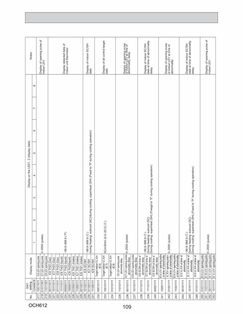
109
No.
SW
1 se
tting
Dis
play
mod
eD
ispl
ay o
n th
e LE
D1,
2 (d
ispl
ay d
ata)
Not
es12
3456
781
23
45
67
821
710
0110
11IC
6 LEV
open
ing pu
lse0–
2000
(pul
se)
Dis
play
of o
peni
ng p
ulse
of
indo
or L
EV
218
0101
1001
IC7 L
EV op
ening
pulse
219
1101
1001
IC8 L
EV op
ening
pulse
220
0011
1011
IC6
TH23
(Gas
)
−99.
9–99
9.9
(°F)
Dis
play
det
ecte
d da
ta o
f in
door
uni
t the
rmis
tor
221
1011
1011
IC7
TH23
(Gas
)22
201
1110
11IC
8 TH
23 (G
as)
223
1111
1011
IC6
TH22
(liq
uid)
224
0000
0111
IC7
TH22
(liq
uid)
225
1000
0111
IC8
TH22
(liqu
id)
226
0100
0111
IC6
TH21
(int
ake)
227
1100
0111
IC7
TH21
(int
ake)
228
0010
0111
IC8
TH21
(int
ake)
229
1010
0111
IC6
SC
/SH
−99.
9–99
9.9
(:)
durin
g he
atin
g: s
ubco
ol (S
C)/d
urin
g co
olin
g: s
uper
heat
(SH
) (Fi
xed
to "0
" dur
ing
cool
ing
oper
atio
n)D
ispl
ay o
f ind
oor S
C/S
H
data
23
001
1001
11IC
7 S
C/S
H23
111
1001
11IC
8 S
C/S
H
232
0001
0111
Targ
et ind
oor S
C/SH
(IC
6)
SC
m/S
Hm
(0.0
–20.
0) (:
)D
ispl
ay o
f all
cont
rol t
arge
t da
ta23
310
0101
11Ta
rget
indoo
r SC/
SH
(IC7)
234
0101
0111
Targ
et ind
oor S
C/SH
(IC
8)
235
1101
0111
IC6 L
EV op
ening
pulse
ab
norm
ality
delay
0–20
00 (p
ulse
)D
ispl
ay o
f ope
ning
pul
se
of in
door
LE
V a
t tim
e of
ab
norm
ality
del
ay23
600
1101
11IC
7 LE
V op
ening
puls
e ab
norm
ality
delay
237
1011
0111
IC8
LEV
open
ing p
ulse
abno
rmali
ty de
lay
238
0111
0111
IC6
SC/S
H at
time
of
abno
rmali
ty de
lay
−99.
9–99
9.9
(:)
Dur
ing
heat
ing:
sub
cool
(SC
)D
urin
g co
olin
g: s
uper
heat
(SH
) (Fi
xegd
to "0
" dur
ing
cool
ing
oper
atio
n)
Dis
play
of i
ndoo
r SC
/SH
da
ta a
t tim
e of
abn
orm
ality
de
lay
239
1111
0111
IC7
SC/S
H at
time
of
abno
rmali
ty de
lay
240
0000
1111
IC8
SC/S
H at
time
of
abno
rmali
ty de
lay
241
1000
1111
IC6 L
EV op
ening
pulse
at
time o
f abn
orma
lity 0–
2000
(pul
se)
Dis
play
of o
peni
ng p
ulse
of
indo
or L
EV
at t
ime
of
abno
rmal
ity24
201
0011
11IC
7EV
open
ing pu
lse
at tim
e of a
bnor
mality
243
1100
1111
IC8 L
EV op
ening
pulse
at
time o
f abn
orma
lity
244
0010
1111
IC6 S
C/SH
at tim
e of
abno
rmali
ty
−99.
9–99
9.9
(:)
Dur
ing
heat
ing:
sub
cool
(SC
)D
urin
g co
olin
g: s
uper
heat
(SH
) (Fi
xed
to "0
" dur
ing
cool
ing
oper
atio
n)
Dis
play
of i
ndoo
r SC
/SH
da
ta a
t tim
e of
abn
orm
ality
de
lay
245
1010
1111
IC7 S
C/SH
at tim
e of
abno
rmali
ty
246
0110
1111
IC8 S
C/SH
at tim
e of
abno
rmali
ty25
001
0111
11IC
9 LEV
open
ing pu
lse
0–20
00 (p
ulse
)D
ispl
ay o
f ope
ning
pul
se o
f in
door
LE
V25
111
0111
11IC
10 LE
V op
ening
pulse
252
0011
1111
IC11
LEV
open
ing pu
lse25
310
1111
11IC
12 LE
V op
ening
pulse
OCH612
110
9 ELECTRICAL WIRING
9-1. OVERVIEW OF POWER WIRING
9-2. WIRING OF MAIN POWER SUPPLY AND EQUIPMENT CAPACITY9-2-1. Wiring diagram for main power supply
This chapter provides an introduction to electrical wiring for the CITY MULTI-S series, together with notes concerning power wiring, wiring for control (transmission wires and remote controller wires), and the frequency converter.
(1) Use a separate power supply for the outdoor unit and indoor unit.(2) Bear in mind ambient conditions (ambient temperature, direct sunlight, rain water,etc.) when proceeding with the wiring and connections.(3) The wire size is the minimum value for metal conduit wiring. The power cord size should be 1 rank thicker consideration of voltage drops.
Make sure the power-supply voltage does not drop more than 10 %.(4) Specific wiring requirements should adhere to the wiring regulations of the region.(5) Power supply cords of parts of appliances for outdoor use shall not be lighter than polychloroprene sheathed flexible cord (design 60245 IEC57).
For example, use wiring such as YZW.(6) Install an earth longer than other cables.
Warning:· Be sure to use specified wires to connect so that no external force is imparted to terminal connections. If connections are not fixed firmly,
it may cause heating or fire.· Be sure to use the appropriate type of overcurrent protection switch. Note that generated overcurrent may include some amount of direct
current.
Caution:· Some installation site may require attachment of an earth leakage breaker. If no earth leakage breaker is installed, it may cause an electric
shock.· Do not use anything other than breaker and fuse with correct capacity. Using fuse and wire or copper wire with too large capacity may cause a
malfunction of unit or fire.Be sure to install N-Line. Without N-Line, it could cause damage to the unit.·
Schematic Drawing of Wiring
208/230 V AC 60 Hz208/230 V AC 60 Hz
L1/L2
A
BA
CL1/L2
CL1/L2
CL1/L2
CL1/L2
D
A Switch (Breakers for Wiring and Current Leakage)B Outdoor UnitC M-NET Control Indoor unitD Pull Box
Note: The M-NET control indoor unit cannot receive power supplied from an outdoor unit, so provide it with power separately.
; ;
;
; ;
OCH612

111
9-2-2. Cross section area of Wire for Main Power and ON/OFF capacitiesPUMY-P36/48NKMU1(-BS)
Thickness of Wire for Main Power Supply and On/Off Capacities
ModelPower Supply
Minimum Wire Thickness (AWG [mm2]) Breaker for
Wiring*1Breaker for Current
LeakageMinimum cir-cuit ampacity
Maximum rating of over current protec-
tor deviceMain Cable*2 Ground
Outdoor Unit P36/48 208/230 VAC, 60 Hz AWG8 [8.4] AWG8 [8.4] 40 A 40 A 30 mA 0.1 sec. or less 31 A 44 A
Indoor Unit 208/230 VAC, 60 Hz Refer to installation manual of indoor unit.
*2. Use copper supply wires. Use the electric wires over the rating voltage 300 V..
Total operating current of the indoor unitMinimum wire thickness (AWG [mm2])
Ground-fault interruper *1Local switch (A) Breaker for wiring
(NFB)Main Cable Branch Ground Capacity FuseF0 = 15 A or less *2 14/2.1 14/2.1 14/2.1 15 A current sensitivity *3 15 15 15F0 = 20 A or less *2 12/3.3 12/3.3 12/3.3 20 A current sensitivity *3 20 20 20F0 = 30 A or less *2 10/5.5 10/5.5 10/5.3 30 A current sensitivity *3 30 30 30
Apply to IEC61000-3-3 about max. permissive system impedance.*1 The Ground-fault interrupter should support inverter circuit. The Ground-fault interrupter should combine using of local switch or wiring breaker.*2 Please take the larger of F1 or F2 as the value for F0.F1 = Total operating maximum current of the indoor units × 1.2F2 = {V1 × (Quantity of Type1)/C} + {V1 × (Quantity of Type2)/C} + {V1 × (Quantity of Type3)/C} + {V1 × (Quantity of Others)/C}
C : Multiple of tripping current at tripping time 0.01sPlease pick up “C” from the tripping characteristic of the breaker.
= 14.65
+ V3 × (Wire length [km])
G1 Current sensitivity30 or less 30 mA 0.1 sec or less
100 or less 100 mA 0.1 sec or less
Wire thickness (AWG [mm2]) V314/2.1 4812/3.3 5610/5.3 66
1. Use a separate power supply for the outdoor unit and indoor unit.2. Bear in mind ambient conditions (ambient temperature,direct sunlight, rain water,etc.) when proceeding with the wiring and connections.3. The wire size is the minimum value for metal conduit wiring. The power cord size should be 1 rank thicker consideration of voltage drops. Make sure the power-supply voltage does not drop more than 10%.4.
6000
600
60
10
1
0.1
0.011 2 3 4 6 8
C
10 20
Sample chartTr
ippi
ng T
ime
[s]
Rated Tripping current (x)
SAMPLE
*1. A breaker with at least 3.0 mm [1/8 inch] contact separation in each poles shall be provided. Use non-fuse breaker (NF) or earth leakage breaker (NV).
<Example of “F2” calculation>* Condition PEFY-NMSU × 4 + PEFY-NMAU × 1, C = 8 (refer to right sample chart)F2 = 19.8 × 4/8 + 38 × 1/8
16 A breaker (Tripping current = 8 × 16 A at 0.01 s)* 3 Current sensitivity is calculated using the following formula.G1 = V2 × (Quantity of Type1) + V2 × (Quantity of Type2) + V2 × (Quantity of Type3) + V2 × (Quantity of Others)
Indoor unit V1 V2
Type 1PKFY-P·NHMU, PKFY-P·NKMU, PEFY-P·NMSU, PLFY-P·NEMU, PLFY-EP·NEMU, PMFY-P·NBMU, PCFY-P·NKMU
19.8 2.4
Type 2 PEFY-P·NMAU, PVFY-P·NAMU 38.0 1.6Type 3 PKFY-P·NBMU, PLFY-P·NCMU 3.5 2.4
Others PFFY-P·NEMU, PFFY-P·NRMU, PDFY-P·NMU, PEFY-P·NMHU 0.0 0.0
OCH612
112
9-3. DESIGN FOR CONTROL WIRINGPlease note that the types and numbers of control wires needed by the CITY MULTI-S series depend on the remote controllers and whether they are linked with the system or not.
9-3-1. Selection number of control wires
9-4. WIRING TRANSMISSION CABLES
M-NET remote controller
UseRemote controller used in system control operations.• Group operation involving different refrigerant systems.• Linked operation with upper control system.
Remote controller → indoor unit
2-core wire (non-polar)
Tran
smis
sion
w
ires
Wires connecting → indoor units
Wires connecting → indoor units with outdoor unit
Wires connecting → outdoor units
9-4-1. Types of control cables1. Wiring transmission cables• Types of transmission cables: Shielding wire CVVS, CPEVS or MVVS• Cable diameter: More than 13.5 ft2 [1.25 mm2] • Maximum wiring length: Within 656 ft [200 m]
2. M-NET Remote control cables
Kind of remote control cable Shielding wire (2-core) CVVS, CPEVS or MVVS
Cable diameter AWG 20 to AWG 16 [0.5 to 1.25 mm2]
Remarks When 10 m is exceeded, use a cable with the same specifi cations as transmission line wiring.
3. MA Remote control cables
Kind of remote control cable Sheathed 2-core cable (unshielded) CVV
Cable diameterAWG 22 to AWG 16 [0.3 to 1.25 mm2] AWG 18 to AWG 16 [0.75 to 1.25 mm2]*
Remarks Within 656 ft [200 m]
* Connected with simple remote controller.
9-4-2. Wiring examples• Controller name, symbol and allowable number of controllers.
Name Symbol Allowable number of controllers
Outdoor unit controller OC ―
Indoor unit controller M-ICPUMY-P36 1 to 7 units per 1 OC
PUMY-P48 1 to 10 units per 1 OC
Remote controller RCM-NET RC Maximum of 12 controllers for 1 OC
(Can not be connected if Branch box is used.)
MA-RC Maximum of 2 per group
Note that the number of connectable units may be limited by some conditions such as an indoor unit's capacity or each unit's equivalent power consumption. (Refer to DATA BOOK.)
OCH612
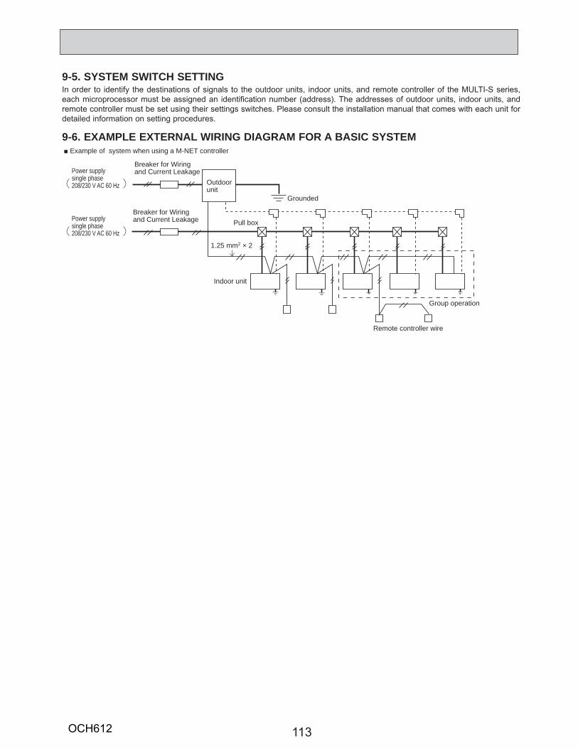
113
9-5. SYSTEM SWITCH SETTINGIn order to identify the destinations of signals to the outdoor units, indoor units, and remote controller of the MULTI-S series, each microprocessor must be assigned an identification number (address). The addresses of outdoor units, indoor units, and remote controller must be set using their settings switches. Please consult the installation manual that comes with each unit for detailed information on setting procedures.
9-6. EXAMPLE EXTERNAL WIRING DIAGRAM FOR A BASIC SYSTEM
Outdoorunit
Grounded
Group operation
Remote controller wire
Pull box
Indoor unit
Breaker for Wiring and Current Leakage
Breaker for Wiring and Current Leakage
1.25 mm2 × 2
Power supplysingle phase208/230 V AC 60 Hz
Power supplysingle phase 208/230 V AC 60 Hz
Example of system when using a M-NET controller
OCH612

114
(3) Method of obtaining system power factorUse the following formula and the total power and current obtained in parts 1 and 2 on the above tables to calculate the system power factor.
System power factor =(Total system power consumption)
(Total system current × voltage) o 100 %
9-7-2. Applying to an electric power company for power and total currentCalculations should be performed separately for heating and cooling employing the same methods; use the largest resulting value in your application to the electric power company.
9-7. METHOD FOR OBTAINING ELECTRICAL CHARACTERISTICS WHEN A CAPACITY AGREEMENT IS TO BE SIGNED WITH AN ELECTRIC POWER COMPANY
The electrical characteristics of connected indoor unit system for air conditioning systems, including the MULTI-S series, depend on the arrangement of the indoor and outdoor units.First read the data on the selected indoor and outdoor units and then use the following formulas to calculate the electrical characteristics before applying for a capacity agreement with the local electric power company.
9-7-1. Obtaining the electrical characteristics of a CITY MULTI-S series system (1) Procedure for obtaining total power consumption
*The power consumption of the outdoor unit will vary depending on the total capacity of the selected indoor units.
(2) Method of obtaining total current
The current through the outdoor unit will vary depending on the total capacity of the selected indoor units.
Page numbers in this technical manual Power consumptionTotal power consumption of each indoor unit See the technical manual of each indoor unit 1
Power consumption of outdoor unit* Standard capacity diagram— Refer to 4-3. 2
Total power consumption of system See the technical manual of each indoor unit 1+2 <kW>
Page numbers in this technical manual SubtotalTotal current through each indoor unit See the technical manual of each indoor unit 1
Current through outdoor unit* Standard capacity diagram— Refer to 4-3. 2
Total current through system See the technical manual of each indoor unit 1+2 <A>
OCH612
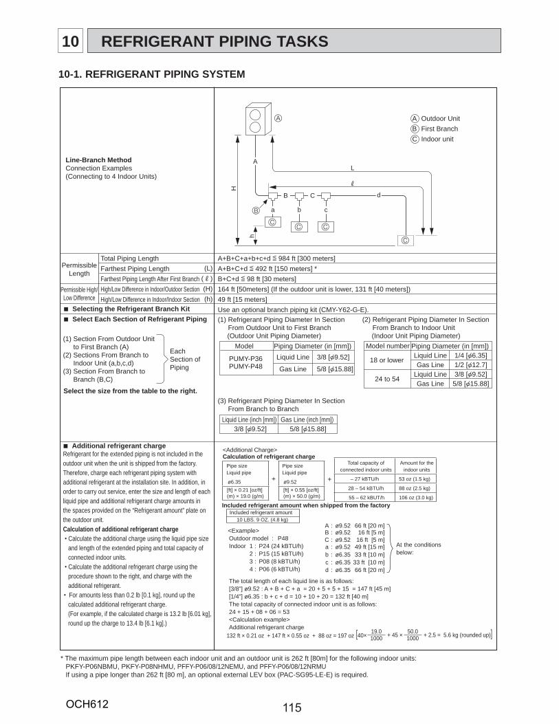
115
10 REFRIGERANT PIPING TASKS
10-1. REFRIGERANT PIPING SYSTEM
Line-Branch MethodConnection Examples(Connecting to 4 Indoor Units)
Liquid Line
Gas Line
Piping Diameter (in [mm])Model
Liquid Line (inch [mm]) Gas Line (inch [mm]) 5/8 [{15.88]3/8 [{9.52]
Liquid LineGas Line
Liquid LineGas Line
Piping Diameter (in [mm])Model number
18 or lower
24 to 54
1/4 [{6.35]1/2 [{12.7]3/8 [{9.52]5/8 [{15.88]
Outdoor UnitFirst BranchIndoor unit
ABC
A+B+C+a+b+c+d [ 984 ft [300 meters]A+B+C+d [ 492 ft [150 meters] *B+C+d [ 98 ft [30 meters]164 ft [50meters] (If the outdoor unit is lower, 131 ft [40 meters])49 ft [15 meters]Use an optional branch piping kit (CMY-Y62-G-E).
Total Piping LengthFarthest Piping LengthFarthest Piping Length After First BranchHigh/Low Difference in Indoor/Outdoor SectionHigh/Low Difference in Indoor/Indoor Section
PermissibleLength
Permissible High/Low Difference
(L)(R)(H)(h)
Selecting the Refrigerant Branch Kit Select Each Section of Refrigerant Piping
Additional refrigerant charge
Select the size from the table to the right.
(1) Refrigerant Piping Diameter In Section From Outdoor Unit to First Branch (Outdoor Unit Piping Diameter)(1) Section From Outdoor Unit
to First Branch (A)(2) Sections From Branch to Indoor Unit (a,b,c,d)(3) Section From Branch to Branch (B,C)
(3) Refrigerant Piping Diameter In Section From Branch to Branch
(2) Refrigerant Piping Diameter In Section From Branch to Indoor Unit (Indoor Unit Piping Diameter)
EachSection ofPiping
Refrigerant for the extended piping is not included in the outdoor unit when the unit is shipped from the factory. Therefore, charge each refrigerant piping system with additional refrigerant at the installation site. In addition, in order to carry out service, enter the size and length of each liquid pipe and additional refrigerant charge amounts inthe spaces provided on the “Refrigerant amount” plate on the outdoor unit.Calculation of additional refrigerant charge
Calculate the additional charge using the liquid pipe size and length of the extended piping and total capacity of connected indoor units. Calculate the additional refrigerant charge using the procedure shown to the right, and charge with the additional refrigerant.For amounts less than 0.2 lb [0.1 kg], round up the calculated additional refrigerant charge.(For example, if the calculated charge is 13.2 lb [6.01 kg], round up the charge to 13.4 lb [6.1 kg].)
3/8 [{9.52]
5/8 [{15.88]PUMY-P36PUMY-P48
* The maximum pipe length between each indoor unit and an outdoor unit is 262 ft [80m] for the following indoor units: PKFY-P06NBMU, PKFY-P08NHMU, PFFY-P06/08/12NEMU, and PFFY-P06/08/12NRMUIf using a pipe longer than 262 ft [80 m], an optional external LEV box (PAC-SG95-LE-E) is required.
B
A
A
H
B C
L
R
d
a
h
b c
C
C
C C
Pipe sizeLiquid pipe
+
Pipe sizeLiquid pipe
ø6.35 ø9.52[ft] × 0.21 [oz/ft](m) × 19.0 (g/m)
[ft] × 0.55 [oz/ft](m) × 50.0 (g/m)
<Additional Charge>Calculation of refrigerant charge
+
Total capacity of connected indoor units
Amount for the indoor units
– 27 kBTU/h 53 oz (1.5 kg)
28 – 54 kBTU/h 88 oz (2.5 kg)
55 – 62 kBUT/h 106 oz (3.0 kg)Included refrigerant amount when shipped from the factory
Included refrigerant amount
[40 × 19.0 + 45 × 50.0 + 2.5 = 5.6 kg (rounded up)]1000 1000
<Example>Outdoor model : P48Indoor 1 : P24 (24 kBTU/h)
A : ø9.52 66 ft [20 m]B : ø9.52 16 ft [5 m]C : ø9.52 16 ft [5 m] a : ø9.52 49 ft [15 m]
2 : P15 (15 kBTU/h) b : ø6.35 33 ft [10 m] 3 : P08 (8 kBTU/h) c : ø6.35 33 ft [10 m] 4 : P06 (6 kBTU/h) d : ø6.35 66 ft [20 m]
The total length of each liquid line is as follows:[3/8”] ø9.52 : A + B + C + a = 20 + 5 + 5 + 15 = 147 ft [45 m][1/4”] ø6.35 : b + c + d = 10 + 10 + 20 = 132 ft [40 m]The total capacity of connected indoor unit is as follows:24 + 15 + 08 + 06 = 53<Calculation example>Additional refrigerant charge
At the conditions below:
10 LBS. 9 OZ. (4.8 kg)
132 ft × 0.21 oz + 147 ft × 0.55 oz + 88 oz = 197 oz
OCH612
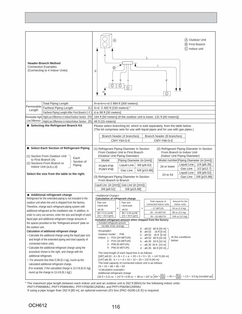
116
Header-Branch MethodConnection Examples(Connecting to 4 Indoor Units)
Outdoor UnitFirst BranchIndoor unit
ABC
A+a+b+c+d [ 984 ft [300 meters]A+d [ 492 ft [150 meters] *d is 98 ft [30 meters]164 ft [50 meters] (If the outdoor unit is lower, 131 ft [40 meters])49 ft [15 meters] Please select branching kit, which is sold separately, from the table below.(The kit comprises sets for use with liquid pipes and for use with gas pipes.)
Total Piping LengthFarthest Piping LengthFarthest Piping Length After First BranchHigh/Low Difference in Indoor/Outdoor SectionHigh/Low Difference in Indoor/Indoor Section
PermissibleLength
Permissible High/Low Difference
(L)(R)(H)(h)
Select Each Section of Refrigerant Piping
Selecting the Refrigerant Branch Kit
Select the size from the table to the right.
(1) Section From Outdoor Unit to First Branch (A)(2) Sections From Branch to Indoor Unit (a,b,c,d)
EachSection ofPiping
Branch header (4 branches)CMY-Y64-G-E
Branch header (8 branches)CMY-Y68-G-E
* The maximum pipe length between each indoor unit and an outdoor unit is 262 ft [80m] for the following indoor units: PKFY-P06NBMU, PKFY-P08NHMU, PFFY-P06/08/12NEMU, and PFFY-P06/08/12NRMUIf using a pipe longer than 262 ft [80 m], an optional external LEV box (PAC-SG95-LE-E) is required.
B
A
A
a b c
C
cCC
d
H
h
L
r
Additional refrigerant chargeRefrigerant for the extended piping is not included in the outdoor unit when the unit is shipped from the factory. Therefore, charge each refrigerant piping system with additional refrigerant at the installation site. In addition, in order to carry out service, enter the size and length of each liquid pipe and additional refrigerant charge amounts inthe spaces provided on the “Refrigerant amount” plate on the outdoor unit.Calculation of additional refrigerant charge
Calculate the additional charge using the liquid pipe size and length of the extended piping and total capacity of connected indoor units. Calculate the additional refrigerant charge using the procedure shown to the right, and charge with the additional refrigerant.For amounts less than 0.2lb [0.1 kg], round up the
calculated additional refrigerant charge.(For example, if the calculated charge is 13.2 lb [6.01 kg], round up the charge to 13.4 lb [6.1 kg].)
Liquid Line
Gas Line
Piping Diameter (in [mm])Model
Liquid Line (in [mm]) Gas Line (in [mm])5/8 [{15.88]3/8 [{9.52]
Liquid LineGas Line
Liquid LineGas Line
Piping Diameter (in [mm])Model number
18 or lower
24 to 54
1/4 [{6.35]1/2 [{12.7]3/8 [{9.52]5/8 [{15.88]
(1) Refrigerant Piping Diameter In Section From Outdoor Unit to First Branch (Outdoor Unit Piping Diameter)
(3) Refrigerant Piping Diameter In Section From Branch to Branch
(2) Refrigerant Piping Diameter In Section From Branch to Indoor Unit (Indoor Unit Piping Diameter)
3/8 [{9.52]
5/8 [{15.88]PUMY-P36PUMY-P48
Pipe sizeLiquid pipe
+
Pipe sizeLiquid pipe
ø6.35 ø9.52[ft] × 0.21 [oz/ft](m) × 19.0 (g/m)
[ft] × 0.55 [oz/ft](m) × 50.0 (g/m)
<Additional Charge>Calculation of refrigerant charge
+
Total capacity of connected indoor units
Amount for the indoor units
– 27 kBTU/h 53 oz (1.5 kg)
28 – 54 kBTU/h 88 oz (2.5 kg)
55 – 62 kBUT/h 106 oz (3.0 kg)Included refrigerant amount when shipped from the factory
Included refrigerant amount
[40 × 19.0 + 45 × 50.0 + 2.5 = 5.6 kg (rounded up)]1000 1000
<Example>Outdoor model : P48Indoor 1 : P24 (24 kBTU/h)
A : ø9.52 66 ft [20 m]B : ø9.52 16 ft [5 m]C : ø9.52 16 ft [5 m] a : ø9.52 49 ft [15 m]
2 : P15 (15 kBTU/h) b : ø6.35 33 ft [10 m] 3 : P08 (8 kBTU/h) c : ø6.35 33 ft [10 m] 4 : P06 (6 kBTU/h) d : ø6.35 66 ft [20 m]
The total length of each liquid line is as follows:[3/8”] ø9.52 : A + B + C + a = 20 + 5 + 5 + 15 = 147 ft [45 m][1/4”] ø6.35 : b + c + d = 10 + 10 + 20 = 132 ft [40 m]The total capacity of connected indoor unit is as follows:24 + 15 + 08 + 06 = 53<Calculation example>Additional refrigerant charge
At the conditions below:
10 LBS. 9 OZ. (4.8 kg)
132 ft × 0.21 oz + 147 ft × 0.55 oz + 88 oz = 197 oz
OCH612

117
Method of Combined Branching of Lines andHeadersConnection Examples(Connecting to 5 Indoor Units)
Outdoor unit
First branching (branchingjoint)
Branching joint
Indoor unit
Branching header
Blind caps
A
B
C
D
E
F
A+B+C+a+b+c+d+e is 984 ft [300 meters] A+B+b is 492 ft [150 meters] *B+b is 98 tf [30 meters]164 ft [50 meters] (If the outdoor unit is lower, 131 ft [40 meters])49 ft [15 meters]Please select branching kit, which is sold separately, from the table below.(The kit comprises sets for use with liquid pipes and for use with gas pipes.)
Total Piping LengthFarthest Piping LengthFarthest Piping Length After First BranchHigh/Low Difference in Indoor/Outdoor SectionHigh/Low Difference in Indoor/Indoor Section
PermissibleLength
Permissible High/Low Difference
(L)(R)(H)(h)
Selecting the Refrigerant Branch Kit
Select Each Section of Refrigerant Piping
Select the size from the table to the right.
(1) Section From Outdoor Unit to First Branch (A)(2) Sections From Branch to Indoor Unit (a,b,c,d,e)(3) Section From Branch to Branch (B,C)
EachSection ofPiping
Branch JointCMY-Y62-G-E
Branch Header (4 branches)CMY-Y64-G-E
Branch Header (8 branches)CMY-Y68-G-E
Additional refrigerant chargeRefrigerant for the extended piping is not included in the outdoor unit when the unit is shipped from the factory. Therefore, charge each refrigerant piping system with additional refrigerant at the installation site. In addition, in order to carry out service, enter the size and length of each liquid pipe and additional refrigerant charge amounts inthe spaces provided on the “Refrigerant amount” plate on the outdoor unit.Calculation of additional refrigerant charge
Calculate the additional charge using the liquid pipe size and length of the extended piping and total capacity of connected indoor units. Calculate the additional refrigerant charge using the procedure shown to the right, and charge with the additional refrigerant.For amounts less than 0.2 lb [0.1 kg], round up the
calculated additional refrigerant charge.(For example, if the calculated charge is 13.2 lb [6.01 kg], round up the charge to 13.4 lb [6.1 kg].)
* The maximum pipe length between each indoor unit and an outdoor unit is 262 ft [80m] for the following indoor units: PKFY-P06NBMU, PKFY-P08NHMU, PFFY-P06/08/12NEMU, and PFFY-P06/08/12NRMUIf using a pipe longer than 262 ft [80 m], an optional external LEV box (PAC-SG95-LE-E) is required.
B
A
E
F
C D
D D D
D
A
C
b
B 3H
h
4
L
R
5
1
2
c d e
a
Note: Pipe re-branching after the header branching is not possible.
Liquid Line
Gas Line
Piping Diameter(inch [mm])Model
Liquid Line (inch [mm]) Gas Line (inch [mm])5/8 [{15.88]3/8 [{9.52]
Liquid LineGas Line
Liquid LineGas Line
Piping Diameter(inch [mm])Model number
18 or lower
24 to 54
1/4 [{6.35 ]1/2 [{12.7]3/8 [{9.52]5/8 [{15.88]
(1) Refrigerant Piping Diameter In Section From Outdoor Unit to First Branch (Outdoor Unit Piping Diameter)
(3) Refrigerant Piping Diameter In Section From Branch to Branch
(2) Refrigerant Piping Diameter In Section From Branch to Indoor Unit (Indoor Unit Piping Diameter)
3/8 [{9.52]
5/8 [{15.88]PUMY-P36PUMY-P48
Pipe sizeLiquid pipe
+
Pipe sizeLiquid pipe
ø6.35 ø9.52[ft] × 0.21 [oz/ft](m) × 19.0 (g/m)
[ft] × 0.55 [oz/ft](m) × 50.0 (g/m)
<Additional Charge>Calculation of refrigerant charge
+
Total capacity of connected indoor units
Amount for the indoor units
– 27 kBTU/h 53 oz (1.5 kg)
28 – 54 kBTU/h 88 oz (2.5 kg)
55 – 62 kBUT/h 106 oz (3.0 kg)Included refrigerant amount when shipped from the factory
Included refrigerant amount
[40 × 19.0 + 45 × 50.0 + 2.5 = 5.6 kg (rounded up)]1000 1000
<Example>Outdoor model : P48Indoor 1 : P24 (24 kBTU/h)
A : ø9.52 66 ft [20 m]B : ø9.52 16 ft [5 m]C : ø9.52 16 ft [5 m] a : ø9.52 49 ft [15 m]
2 : P15 (15 kBTU/h) b : ø6.35 33 ft [10 m] 3 : P08 (8 kBTU/h) c : ø6.35 33 ft [10 m] 4 : P06 (6 kBTU/h) d : ø6.35 66 ft [20 m]
The total length of each liquid line is as follows:[3/8”] ø9.52 : A + B + C + a = 20 + 5 + 5 + 15 = 147 ft [45 m][1/4”] ø6.35 : b + c + d = 10 + 10 + 20 = 132 ft [40 m]The total capacity of connected indoor unit is as follows:24 + 15 + 08 + 06 = 53<Calculation example>Additional refrigerant charge
At the conditions below:
10 LBS. 9 OZ. (4.8 kg)
132 ft × 0.21 oz + 147 ft × 0.55 oz + 88 oz = 197 oz
OCH612
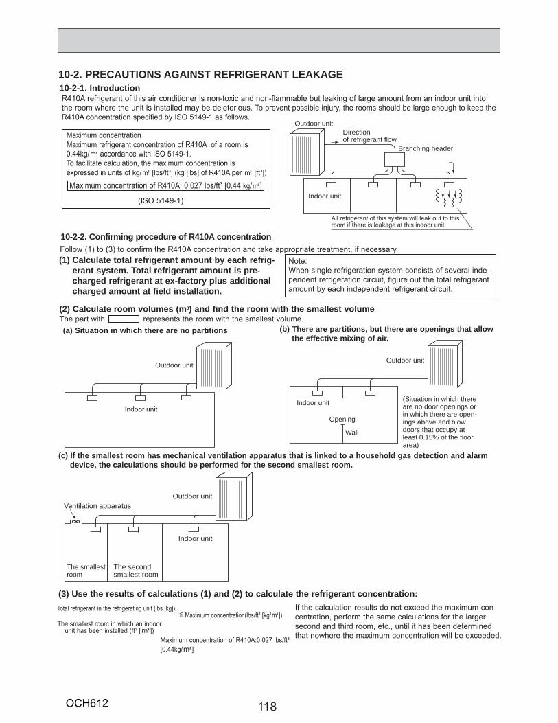
118
10-2. PRECAUTIONS AGAINST REFRIGERANT LEAKAGE10-2-1. IntroductionR410A refrigerant of this air conditioner is non-toxic and non-flammable but leaking of large amount from an indoor unit into the room where the unit is installed may be deleterious. To prevent possible injury, the rooms should be large enough to keep the R410A concentration specified by ISO 5149-1 as follows.
Note:When single refrigeration system consists of several inde-pendent refrigeration circuit, figure out the total refrigerant amount by each independent refrigerant circuit.
Follow (1) to (3) to confirm the R410A concentration and take appropriate treatment, if necessary.(1) Calculate total refrigerant amount by each refrig-
erant system. Total refrigerant amount is pre-charged refrigerant at ex-factory plus additional charged amount at field installation.
(2) Calculate room volumes (m3) and find the room with the smallest volumeThe part with represents the room with the smallest volume.
If the calculation results do not exceed the maximum con-centration, perform the same calculations for the larger second and third room, etc., until it has been determined that nowhere the maximum concentration will be exceeded.
Indoor unit
All refrigerant of this system will leak out to thisroom if there is leakage at this indoor unit.
Directionof refrigerant flow
Outdoor unit
Branching header
Maximum concentrationMaximum refrigerant concentration of R410A of a room is 0.44kg/K accordance with ISO 5149-1. To facilitate calculation, the maximum concentration is expressed in units of kg/K [lbs/ft³] (kg [lbs] of R410A per K [ft³])
(ISO 5149-1)
Maximum concentration of R410A: 0.027 lbs/ft³ [0.44 kg/K]
10-2-2. Confirming procedure of R410A concentration
(b) There are partitions, but there are openings that allow the effective mixing of air.
(c) If the smallest room has mechanical ventilation apparatus that is linked to a household gas detection and alarm device, the calculations should be performed for the second smallest room.
Total refrigerant in the refrigerating unit (lbs [kg]) [ Maximum concentration(lbs/ft³ [kg/K])The smallest room in which an indoor unit has been installed (ft³ [K]) Maximum concentration of R410A:0.027 lbs/ft³ [0.44kg/K]
(a) Situation in which there are no partitions
(3) Use the results of calculations (1) and (2) to calculate the refrigerant concentration:
Indoor unit
The smallestroom
The secondsmallest room
Outdoor unitVentilation apparatus
Indoor unit
Opening
Wall
Outdoor unit
(Situation in which thereare no door openings orin which there are open-ings above and blowdoors that occupy atleast 0.15% of the floorarea)
Indoor unit
Outdoor unit
OCH612
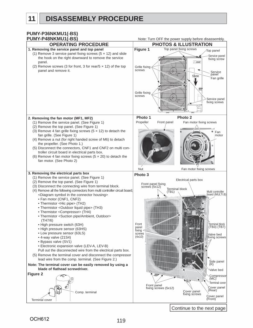
119
OPERATING PROCEDURE1. Removing the service panel and top panel
(1) Remove 3 service panel fixing screws (5 × 12) and slide the hook on the right downward to remove the service panel.
(2) Remove screws (3 for front, 3 for rear/5 × 12) of the top panel and remove it.
2. Removing the fan motor (MF1, MF2)(1) Remove the service panel. (See Figure 1)(2) Remove the top panel. (See Figure 1)(3) Remove 4 fan grille fixing screws (5 × 12) to detach the
fan grille. (See Figure 1)(4) Remove a nut (for right handed screw of M6) to detach
the propeller. (See Photo 1.)(5) Disconnect the connectors, CNF1 and CNF2 on multi con-
troller circuit board in electrical parts box.(6) Remove 4 fan motor fixing screws (5 × 20) to detach the
fan motor. (See Photo 2)
Photo 33. Removing the electrical parts box(1) Remove the service panel. (See Figure 1)(2) Remove the top panel. (See Figure 1)(3) Disconnect the connecting wire from terminal block.(4) Remove all the following connectors from multi controller circuit board;
<Diagram symbol in the connector housing>• Fan motor (CNF1, CNF2) • Thermistor <Hic pipe> (TH2) • Thermistor <Outdoor liquid pipe> (TH3) • Thermistor <Compressor> (TH4) • Thermistor <Suction pipe/Ambient, Outdoor> (TH7/6)• High pressure switch (63H) • High pressure sensor (63HS) • Low pressure sensor (63LS) • 4-way valve (21S4) • Bypass valve (SV1)• Electronic expansion valve (LEV-A, LEV-B)Pull out the disconnected wire from the electrical parts box.
(5) Remove the terminal cover and disconnect the compressor lead wire from the comp. terminal. (See Figure 2.)
Note: The terminal cover can be easily removed by using a blade of flathead screwdriver.
Figure 1
PUMY-P36NKMU1(-BS)PUMY-P48NKMU1(-BS)
Electrical parts box
Terminal block(TB1)
Terminal cover
Cover panel (Front)
Cover panel fixing screws
Compressor (MC)
Valve bed
Valve bed fixing screws
Side panel (R)
Multi controllerboard (MULTI.B)
Terminal block(TB3) (TB7)
Photo 1Propeller Front panel
Nut
Photo 2
Top panel fixing screws Top panel
Service panelfixing screws
Service panelFan grille
Grille fixing screws
Grille fixing screws
Slide
Service panelfixing screw
Front panel fixing screws (5x12)
Front panelfixing screws (4x10)
Front panel fixing screws (5x12)
Note: Turn OFF the power supply before disassembly.
Continue to the next page
Fan motor fixing screws
Fan motor
Fan motor fixing screws
Figure 2
Terminal cover
Comp. terminalCover panel (Rear)
11 DISASSEMBLY PROCEDURE
PHOTOS & ILLUSTRATION
OCH612
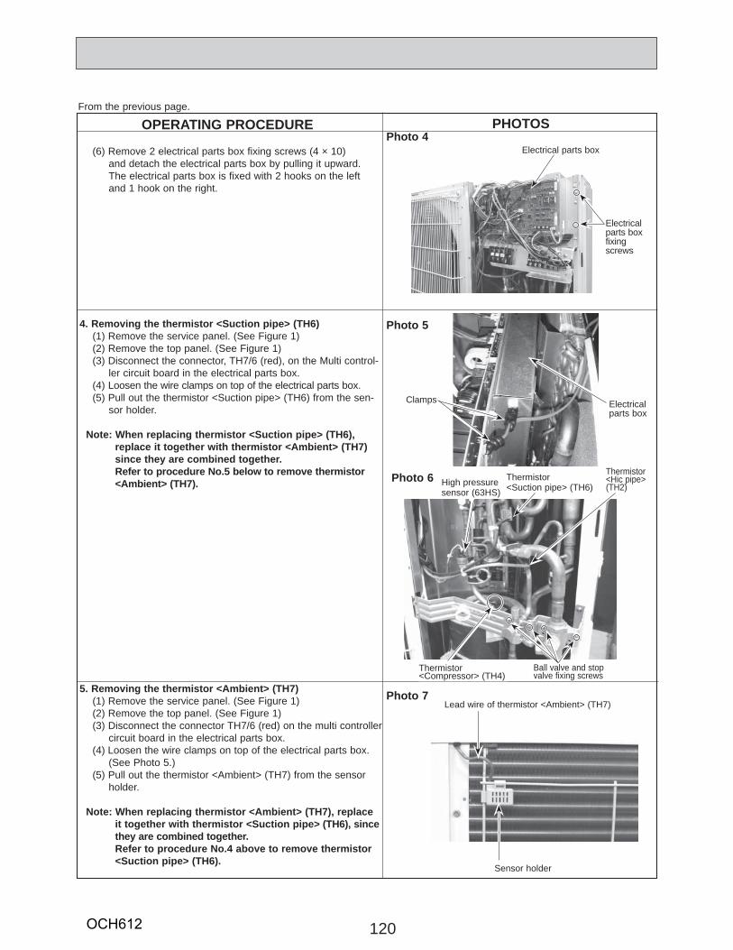
120
OPERATING PROCEDUREPhoto 4
(6) Remove 2 electrical parts box fixing screws (4 × 10) and detach the electrical parts box by pulling it upward. The electrical parts box is fixed with 2 hooks on the left and 1 hook on the right.
From the previous page.
Photo 54. Removing the thermistor <Suction pipe> (TH6)(1) Remove the service panel. (See Figure 1)(2) Remove the top panel. (See Figure 1)(3) Disconnect the connector, TH7/6 (red), on the Multi control-
ler circuit board in the electrical parts box.(4) Loosen the wire clamps on top of the electrical parts box.(5) Pull out the thermistor <Suction pipe> (TH6) from the sen-
sor holder.
Note: When replacing thermistor <Suction pipe> (TH6), replace it together with thermistor <Ambient> (TH7) since they are combined together. Refer to procedure No.5 below to remove thermistor <Ambient> (TH7).
5. Removing the thermistor <Ambient> (TH7)(1) Remove the service panel. (See Figure 1)(2) Remove the top panel. (See Figure 1)(3) Disconnect the connector TH7/6 (red) on the multi controller
circuit board in the electrical parts box.(4) Loosen the wire clamps on top of the electrical parts box.
(See Photo 5.)(5) Pull out the thermistor <Ambient> (TH7) from the sensor
holder.
Note: When replacing thermistor <Ambient> (TH7), replace it together with thermistor <Suction pipe> (TH6), since they are combined together. Refer to procedure No.4 above to remove thermistor <Suction pipe> (TH6).
Photo 7Lead wire of thermistor <Ambient> (TH7)
Sensor holder
Photo 6
Electricalparts box
Clamps
High pressure sensor (63HS)
Thermistor <Suction pipe> (TH6)
Thermistor <Compressor> (TH4)
Thermistor<Hic pipe> (TH2)
Ball valve and stop valve fixing screws
PHOTOS
Electrical parts box
Electricalparts boxfixingscrews
OCH612
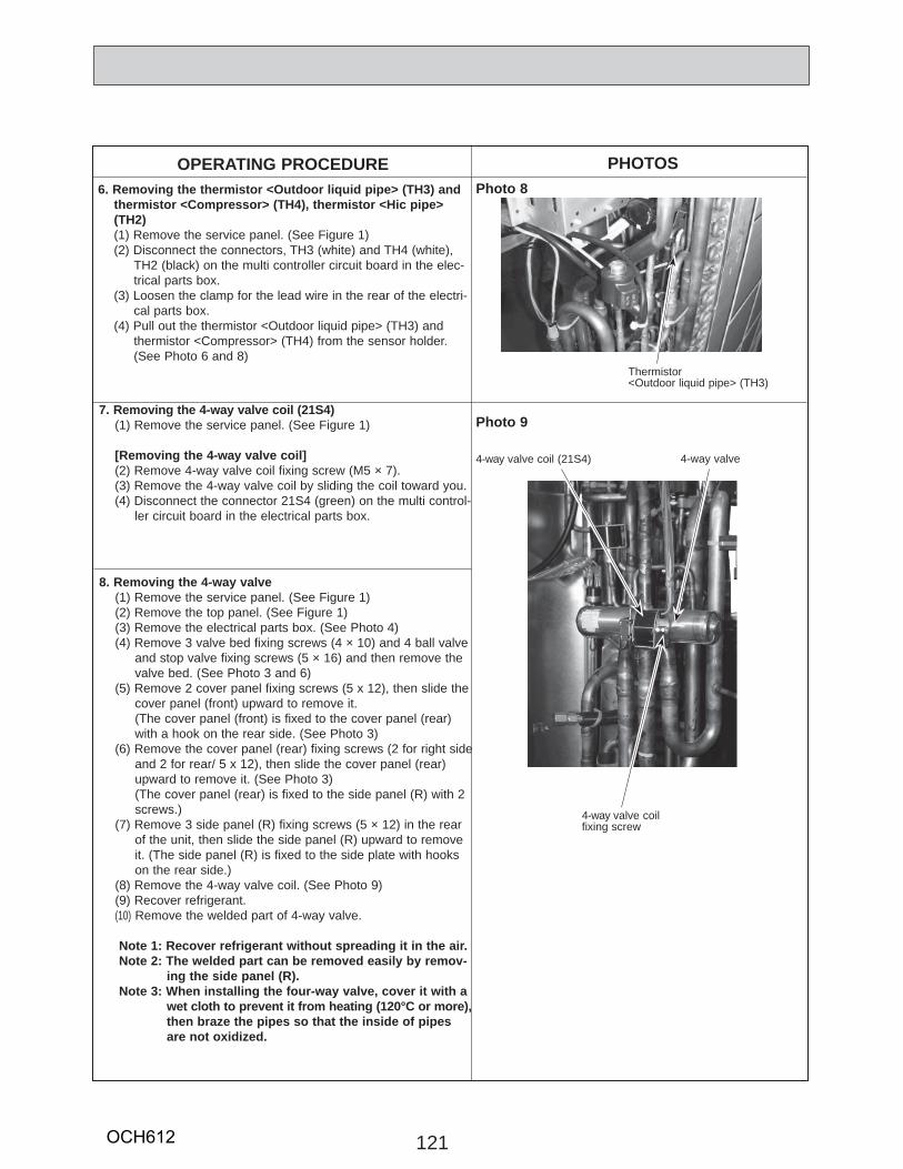
Photo 9
4-way valve coil (21S4) 4-way valve
4-way valve coil fixing screw
121
7. Removing the 4-way valve coil (21S4) (1) Remove the service panel. (See Figure 1)
[Removing the 4-way valve coil](2) Remove 4-way valve coil fixing screw (M5 × 7).(3) Remove the 4-way valve coil by sliding the coil toward you.(4) Disconnect the connector 21S4 (green) on the multi control-
ler circuit board in the electrical parts box.
OPERATING PROCEDURE PHOTOSPhoto 86. Removing the thermistor <Outdoor liquid pipe> (TH3) and
thermistor <Compressor> (TH4), thermistor <Hic pipe> (TH2)(1) Remove the service panel. (See Figure 1)(2) Disconnect the connectors, TH3 (white) and TH4 (white),
TH2 (black) on the multi controller circuit board in the elec-trical parts box.
(3) Loosen the clamp for the lead wire in the rear of the electri-cal parts box.
(4) Pull out the thermistor <Outdoor liquid pipe> (TH3) and thermistor <Compressor> (TH4) from the sensor holder.
(See Photo 6 and 8)
8. Removing the 4-way valve(1) Remove the service panel. (See Figure 1)(2) Remove the top panel. (See Figure 1)(3) Remove the electrical parts box. (See Photo 4)(4) Remove 3 valve bed fixing screws (4 × 10) and 4 ball valve
and stop valve fixing screws (5 × 16) and then remove the valve bed. (See Photo 3 and 6)
(5) Remove 2 cover panel fixing screws (5 x 12), then slide the cover panel (front) upward to remove it.
(The cover panel (front) is fixed to the cover panel (rear) with a hook on the rear side. (See Photo 3)
(6) Remove the cover panel (rear) fixing screws (2 for right side and 2 for rear/ 5 x 12), then slide the cover panel (rear) upward to remove it. (See Photo 3)
(The cover panel (rear) is fixed to the side panel (R) with 2 screws.)
(7) Remove 3 side panel (R) fixing screws (5 × 12) in the rear of the unit, then slide the side panel (R) upward to remove it. (The side panel (R) is fixed to the side plate with hooks on the rear side.)
(8) Remove the 4-way valve coil. (See Photo 9)(9) Recover refrigerant.(10) Remove the welded part of 4-way valve.
Note 1: Recover refrigerant without spreading it in the air.Note 2: The welded part can be removed easily by remov-
ing the side panel (R).Note 3: When installing the four-way valve, cover it with a
wet cloth to prevent it from heating (120°C or more), then braze the pipes so that the inside of pipes
are not oxidized.
Thermistor <Outdoor liquid pipe> (TH3)
OCH612
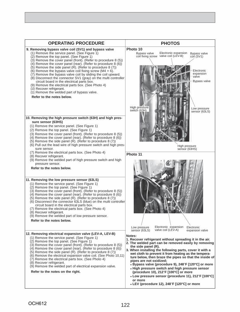
122
OPERATING PROCEDURE PHOTOS9. Removing bypass valve coil (SV1) and bypass valve
(1) Remove the service panel. (See Figure 1)(2) Remove the top panel. (See Figure 1)(3) Remove the cover panel (front). (Refer to procedure 8 (5))(4) Remove the cover panel (rear). (Refer to procedure 8 (6))(5) Remove the side panel (R). (Refer to procedure 8 (7))(6) Remove the bypass valve coil fixing screw (M4 × 6).(7) Remove the bypass valve coil by sliding the coil upward.(8) Disconnect the connector SV1 (gray) on the multi controller
circuit board in the electrical parts box.(9) Remove the electrical parts box. (See Photo 4)(10) Recover refrigerant.(11) Remove the welded part of bypass valve.
Refer to the notes below.
Photo 10
10. Removing the high pressure switch (63H) and high pres-sure sensor (63HS)
(1) Remove the service panel. (See Figure 1)(2) Remove the top panel. (See Figure 1)(3) Remove the cover panel (front). (Refer to procedure 8 (5))(4) Remove the cover panel (rear). (Refer to procedure 8 (6))(5) Remove the side panel (R). (Refer to procedure 8 (7))(6) Pull out the lead wire of high pressure switch and high pres-
sure sensor.(7) Remove the electrical parts box. (See Photo 4)(8) Recover refrigerant.(9) Remove the welded part of high pressure switch and high
pressure sensor. Refer to the notes below.
11. Removing the low pressure sensor (63LS)(1) Remove the service panel. (See Figure 1)(2) Remove the top panel. (See Figure 1)(3) Remove the cover panel (front). (Refer to procedure 8 (5))(4) Remove the cover panel (rear). (Refer to procedure 8 (6))(5) Remove the side panel (R). (Refer to procedure 8 (7))(6) Disconnect the connector 63LS (blue) on the multi controller
circuit board in the electrical parts box. (7) Remove the electrical parts box. (See Photo 4)(8) Recover refrigerant.(9) Remove the welded part of low pressure sensor.
Refer to the notes below.
12. Removing electrical expansion valve (LEV-A, LEV-B)(1) Remove the service panel. (See Figure 1)(2) Remove the top panel. (See Figure 1)(3) Remove the cover panel (front). (Refer to procedure 8 (5))(4) Remove the cover panel (rear). (Refer to procedure 8 (6))(5) Remove the side panel (R). (Refer to procedure 8 (7))(6) Remove the electrical expansion valve coil. (See Photo 10,11)(7) Remove the electrical parts box. (See Photo 4)(8) Recover refrigerant.(9) Remove the welded part of electrical expansion valve.
Refer to the notes on the right.
Photo 11
Low pressure sensor (63LS)
Electronic expansion valve coil (LEV-A)
Electronic expansion valve
High pressure sensor (63HS)
High pressure switch (63H) Low pressure
sensor (63LS)
Bypass valve coil fixing screw
Electronic expansion valve coil (LEV-B)
Bypass valve coil (SV1)
Bypass valve
Electronic expansion valve
Notes:1. Recover refrigerant without spreading it in the air.2. The welded part can be removed easily by removing
the side panel (R).3. When installing the following parts, cover it with a
wet cloth to prevent it from heating as the tempera-ture below, then braze the pipes so that the inside of pipes are not oxidized;• Bypass valve (procedure 9), 248-F [120°C] or more• High pressure switch and high pressure sensor
(procedure 10), 212-F [100°C] or more• Low pressure sensor (procedure 11), 212-F [100°C]
or more• LEV (procedure 12), 248-F [120°C] or more
OCH612
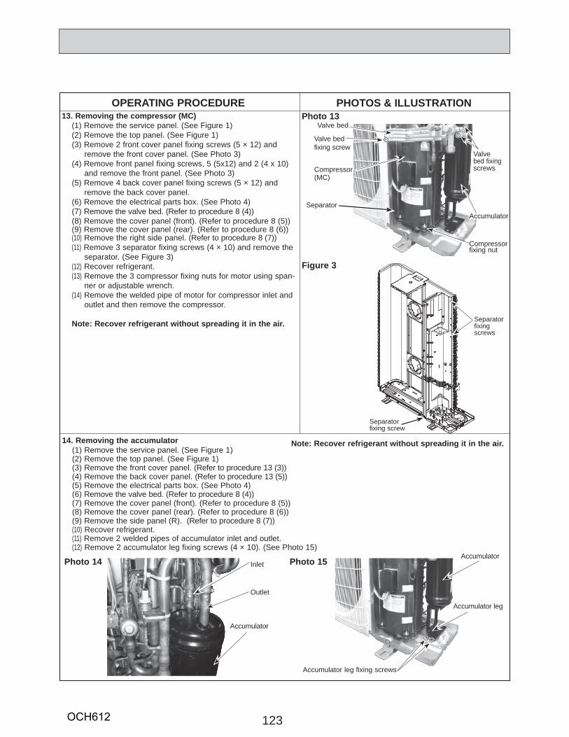
123
Accumulator
OPERATING PROCEDURE PHOTOS & ILLUSTRATION13. Removing the compressor (MC)
(1) Remove the service panel. (See Figure 1)(2) Remove the top panel. (See Figure 1)(3) Remove 2 front cover panel fixing screws (5 × 12) and
remove the front cover panel. (See Photo 3)(4) Remove front panel fixing screws, 5 (5x12) and 2 (4 x 10)
and remove the front panel. (See Photo 3)(5) Remove 4 back cover panel fixing screws (5 × 12) and
remove the back cover panel.(6) Remove the electrical parts box. (See Photo 4)(7) Remove the valve bed. (Refer to procedure 8 (4))(8) Remove the cover panel (front). (Refer to procedure 8 (5))(9) Remove the cover panel (rear). (Refer to procedure 8 (6))(10) Remove the right side panel. (Refer to procedure 8 (7))(11) Remove 3 separator fixing screws (4 × 10) and remove the
separator. (See Figure 3) (12) Recover refrigerant.(13) Remove the 3 compressor fixing nuts for motor using span-
ner or adjustable wrench.(14) Remove the welded pipe of motor for compressor inlet and
outlet and then remove the compressor.
Note: Recover refrigerant without spreading it in the air.
Photo 13
Compressor (MC)
Valve bed
Valve bed fixing screw
Valve bed fixing screws
Compressor fixing nut
14. Removing the accumulator(1) Remove the service panel. (See Figure 1)(2) Remove the top panel. (See Figure 1)(3) Remove the front cover panel. (Refer to procedure 13 (3))(4) Remove the back cover panel. (Refer to procedure 13 (5))(5) Remove the electrical parts box. (See Photo 4)(6) Remove the valve bed. (Refer to procedure 8 (4))(7) Remove the cover panel (front). (Refer to procedure 8 (5))(8) Remove the cover panel (rear). (Refer to procedure 8 (6))(9) Remove the side panel (R). (Refer to procedure 8 (7))(10) Recover refrigerant.(11) Remove 2 welded pipes of accumulator inlet and outlet.(12) Remove 2 accumulator leg fixing screws (4 × 10). (See Photo 15)
Photo 14 Photo 15Inlet
Outlet
Separator
Accumulator
Accumulator leg
Accumulator leg fixing screws
Accumulator
Figure 3
Separator fixing screws
Separator fixing screw
Note: Recover refrigerant without spreading it in the air.
OCH612
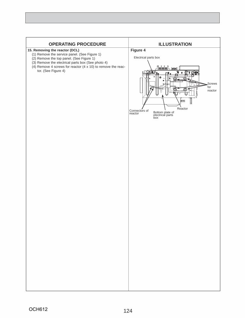
124
OPERATING PROCEDURE
Reactor
Electrical parts box
Figure 4
Screwsfor reactor
Connectors ofreactor
15. Removing the reactor (DCL)(1) Remove the service panel. (See Figure 1)(2) Remove the top panel. (See Figure 1)(3) Remove the electrical parts box (See photo 4)(4) Remove 4 screws for reactor (4 x 10) to remove the reac-
tor. (See Figure 4)
Bottom plate of electrical parts box
ILLUSTRATION
OCH612

125OCH612

cCopyright 2016 MITSUBISHI ELECTRIC CORPORATIONDistributed in May 2016 No.OCH612Made in Japan
New publication, effective May 2016Specifications are subject to change without notice.
HEAD OFFICE : TOKYO BUILDING, 2-7-3, MARUNOUCHI, CHIYODA-KU, TOKYO100-8310, JAPAN


![3. SYSTEM CONTROLLER 3-2. Centralized Controller [AE-200A ...meus1.mylinkdrive.com/files/Eng_Manual_Sect_AE200A_AE-50A.pdf · 3-2. Centralized Controller [AE-200A/AE-50A] ... "Interchange](https://static.fdocuments.in/doc/165x107/5b3874197f8b9ab9068d4c6d/3-system-controller-3-2-centralized-controller-ae-200a-meus1-3-2-centralized.jpg)