Please void OB310. SPLIT-TYPE, HEAT PUMP AIR CONDITIONERS...
53
SERVICE MANUAL CONTENTS 1. FEATURES ·························································3 2. PART NAMES AND FUNCTIONS······················4 3. SPECIFICATION·················································6 4. DATA···································································8 5. OUTLINES AND DIMENSIONS ·······················13 6. WIRING DIAGRAM ··········································15 7. REFRIGERANT SYSTEM DIAGRAM ··············16 8. MICROPROCESSOR CONTROL ····················17 9. SERVICE FUNCTIONS ····································29 10. TROUBLESHOOTING······································31 11. DISASSEMBLY INSTRUCTIONS·····················44 12. PARTS LIST······················································48 13. OPTIONAL PARTS ······················BACK COVER Wireless type Models MSH24WN (W) · MUH24WN SPLIT-TYPE, HEAT PUMP AIR CONDITIONERS The Slim Line. From Mitsubishi Electric. L I S T E D C US INDOOR UNIT Indication of model name MSH24WN OUTDOOR UNIT Indication of model name MUH24WN Remote controller TM Revision: ● PARTS LIST have been partially modified. ● Please void OB310. No. OB310 REVISED EDITION-A
Transcript of Please void OB310. SPLIT-TYPE, HEAT PUMP AIR CONDITIONERS...
SERVICE MANUAL
CONTENTS
1. FEATURES ·························································32. PART NAMES AND FUNCTIONS······················43. SPECIFICATION·················································64. DATA···································································85. OUTLINES AND DIMENSIONS ·······················136. WIRING DIAGRAM ··········································157. REFRIGERANT SYSTEM DIAGRAM ··············168. MICROPROCESSOR CONTROL ····················179. SERVICE FUNCTIONS ····································29
10. TROUBLESHOOTING······································3111. DISASSEMBLY INSTRUCTIONS·····················4412. PARTS LIST······················································4813. OPTIONAL PARTS ······················BACK COVER
Wireless typeModels
MSH24WN (W) · MUH24WN
SPLIT-TYPE, HEAT PUMP AIR CONDITIONERS
The Slim Line.From Mitsubishi Electric.
LIST EDC US
INDOOR UNITIndication of model name MSH24WN
OUTDOOR UNITIndication of model nameMUH24WN
Remotecontroller
TM
Revision: PARTS LIST have been partially modified. Please void OB310.
No. OB310REVISED EDITION-A
OB310--1.qxp 04.1.13 9:47 AM Page 1
Revision:• Parts No. has been changed due to the color change of outdoor unit parts. WHITENEW WHITE (Brighter)• Capillary tubes have been added to parts list.
CAPILLARY TUBE (TAPER PIPE)[0.17X[0.12X11-13/16CAPILLARY TUBE (TAPER PIPE)[0.17X[0.12X1-31/32
E02 785 936
E02 529 936
Part numberPart nameModel
MUH24WN
MUH24WN
Page
51
51
OB310--1.qxp 04.1.13 9:47 AM Page 2
3
LCD wirelessremote controller
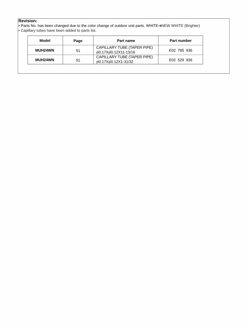
“I FEEL CONTROL” IN OUR LCD WIRELESS REMOTE CONTROLLER WITH ON/OFF PROGRAM TIMERMitsubishi Electric’s new wireless remote controller incorporates a number of advanced features that provide even greater con-trol and ease-to-use. It has a liquid crystal display which indicates such information as mode, fan speed and temperatureselected as well as the programmed ON/OFF timer. It is also equipped with “I Feel Control”, a unique Mitsubishi Electric fea-ture that allows the user to adjust the temperature to exactly the level he or she wants simply by tapping the button thatdescribes present conditions : “Too Cool” or “Too Warm”. The optimum temperature set this way is then memorized for immedi-ate recall whenever the air conditioner is used again.
Select desired air flow direction.REMOTE-CONTROL OPERATION MODEUsing the remote controller, you can select from five airflow set-tings to match room layout and the location of people. Also, youcan set the vane to swing automatically.
AUTO-RESTART FUNCTIONThe auto-restart function restarts the equipment when power isrestored following an outage automatically. Operation resumes inthe mode in which the equipment was running immediately beforethe outage.
HIGH PERFORMANCE ROTARY COMPRESSORThe advanced design of Mitsubishi Electric’s powerful and energyefficient rotary compressor results in lower operating costs andlonger service life.
SWING
MSH24WN
Model
22,000 Btu/h
Cooling capacity
23,600 Btu/h
Heating capacity
10.0
SEER
6.8/5.9
HSPF(44/55)
SWING
FEATURES1
MSH24WN
MUH24WN
OB310--1.qxp 04.1.13 9:47 AM Page 3
4
PART NAMES AND FUNCTIONS2
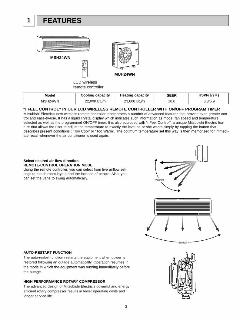
INDOOR UNIT
MSH24WN
Installation plateInstallation plate fixing screw 4 x 25 mm(0.16 x 0.98 in.)Remote controller holderFixing screw for 3 3.5 x 16 mm(0.14 x 0.63 in.) (Black)Battery (AAA) for remote controllerWireless remote controller Felt tape (Used for left or left-rear piping)
1712211
1
2
3
4
5
6
7
MSH24WN
ACCESSORIES
Grille
Air inlet
Remote controlreceiving section
Horizontal vane
Remote controller
Deodorizing filter (option)(Gray sponge type)
Air cleaning filter (option)(White bellows type)
Air filter
Vertical vane
Operation section
(When the grille is opened)
Display section
Operation indicator lamp
Receiving sectionEmergency operation switch
Front panel
Operation Indicator
OUTDOOR UNIT
MUH24WN
OB310--1.qxp 04.1.13 9:47 AM Page 4
5
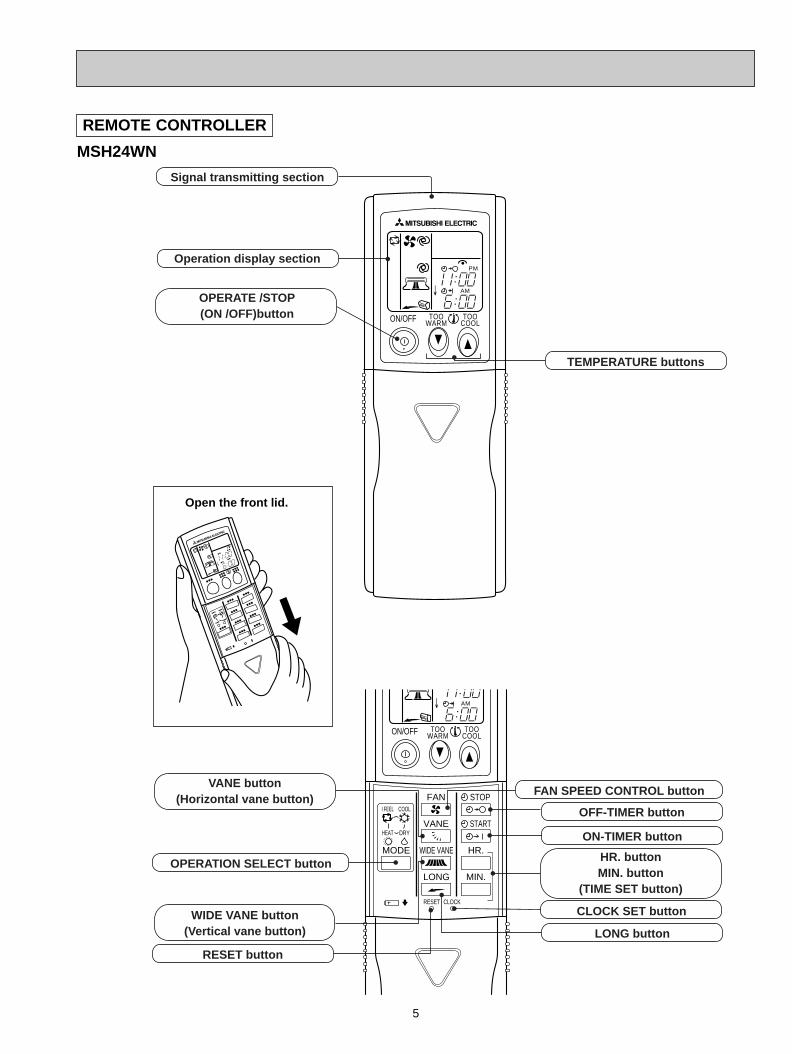
REMOTE CONTROLLER
MSH24WN
ON/OFF TOOCOOL
PM
AM
TOOWARM
ON/OFF
FAN
TOOWARM
TOOCOOL
VANE
MODE
STOP
START
HR.
MIN.
WIDE VANE
LONG
I FEEL COOL
HEAT DRY
PMCLOCK
AM
RESET CLOCK
Open the front lid.
Signal transmitting section
Operation display section
OPERATE /STOP(ON /OFF)button
TEMPERATURE buttons
OPERATION SELECT button
FAN SPEED CONTROL button
OFF-TIMER button
HR. buttonMIN. button
(TIME SET button)
ON-TIMER button
RESET button
VANE button(Horizontal vane button)
CLOCK SET button
LONG button
WIDE VANE button(Vertical vane button)
OB310--1.qxp 04.1.13 9:47 AM Page 5
6
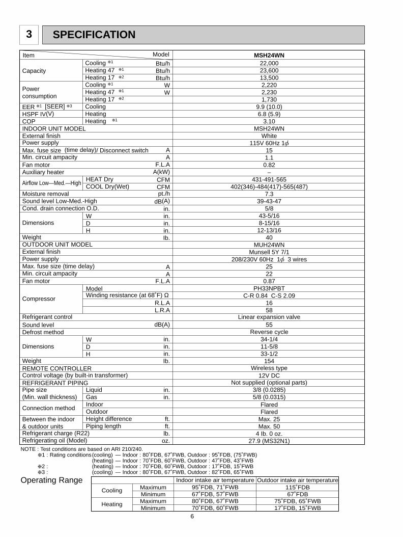
SPECIFICATION3
NOTE : Test conditions are based on ARI 210/240.1 : Rating conditions(cooling) — Indoor : 80˚FDB, 67˚FWB, Outdoor : 95˚FDB, (75˚FWB)
(heating) — Indoor : 70˚FDB, 60˚FWB, Outdoor : 47˚FDB, 43˚FWB2 : (heating) — Indoor : 70˚FDB, 60˚FWB, Outdoor : 17˚FDB, 15˚FWB3 : (cooling) — Indoor : 80˚FDB, 67˚FWB, Outdoor : 82˚FDB, 65˚FWB
Operating Range
Item Model
Capacity
Powerconsumption
EER [SEER] HSPF IV(V)COPINDOOR UNIT MODEL External finishPower supplyMax. fuse size (time delay)/ Disconnect switchMin. circuit ampacityFan motorAuxiliary heater
Airflow Low—Med.—High
Moisture removalSound level Low-Med.-HighCond. drain connection O.D.
Dimensions
WeightOUTDOOR UNIT MODEL External finishPower supplyMax. fuse size (time delay)Min. circuit ampacityFan motor
Compressor
Refrigerant controlSound levelDefrost method
Dimensions
WeightREMOTE CONTROLLERControl voltage (by built-in transformer)REFRIGERANT PIPINGPipe size(Min. wall thickness)
Connection method
Between the indoor& outdoor unitsRefrigerant charge (R22)Refrigerating oil (Model)
Btu/hBtu/hBtu/h
WW
AA
F.L.AA(kW)
CFMCFMpt./h
dB(A)in.in.in.in.Ib.
AA
F.L.A
R.L.AL.R.A
dB(A)
in.in.in.Ib.
in.in.
ft.ft.lb.
oz.
MSH24WN22,00023,60013,5002,2202,2301,730
9.9 (10.0)6.8 (5.9)
3.10MSH24WN
White115V 60Hz 1[
151.1
0.82–
431-491-565402(346)-484(417)-565(487)
7.339-43-47
5/843-5/168-15/16
12-13/1640
MUH24WNMunsell 5Y 7/1
208/230V 60Hz 1[ 3 wires2522
0.87PH33NPBT
C-R 0.84 C-S 2.091658
Linear expansion valve55
Reverse cycle34-1/411-5/833-1/2
154Wireless type
12V DCNot supplied (optional parts)
3/8 (0.0285)5/8 (0.0315)
FlaredFlared
Max. 25Max. 50
4 Ib. 0 oz.27.9 (MS32N1)
1 3
1
1
2
1
1
2
CoolingHeating 47Heating 17CoolingHeating 47Heating 17CoolingHeatingHeating
HEAT DryCOOL Dry(Wet)
WDH
ModelWinding resistance (at 68˚F) Ω
WDH
LiquidGasIndoorOutdoorHeight differencePiping length
1
Cooling
Heating
MaximumMinimumMaximumMinimum
Indoor intake air temperature95˚FDB, 71˚FWB67˚FDB, 57˚FWB80˚FDB, 67˚FWB70˚FDB, 60˚FWB
Outdoor intake air temperature115˚FDB67˚FDB
75˚FDB, 65˚FWB17˚FDB, 15˚FWB
OB310--1.qxp 04.1.13 9:47 AM Page 6
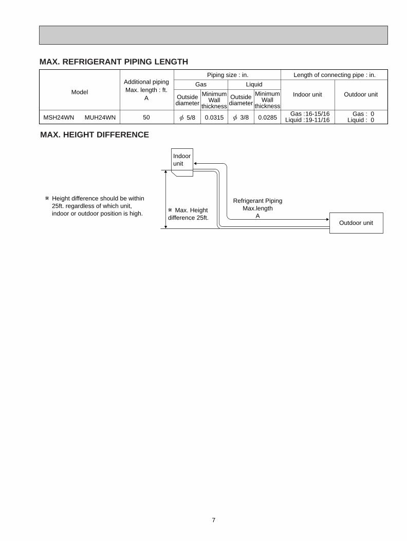
7
Indoor unit
w Max. Heightdifference 25ft.
Outdoor unit
Refrigerant Piping Max.length
A
w Height difference should be within 25ft. regardless of which unit, indoor or outdoor position is high.
MAX. HEIGHT DIFFERENCE
Outside diameter
MinimumWall
thickness
Outside diameter
MinimumWall
thickness
MSH24WN MUH24WN
Additional pipingMax. length : ft.
A
50
Gas
Piping size : in. Length of connecting pipe : in.
Liquid
Indoor unit Outdoor unitModel
Gas :Liquid :
00
Gas :Liquid :
16-15/1619-11/16[ 5/8 [ 3/80.0315 0.0285
MAX. REFRIGERANT PIPING LENGTH
OB310--1.qxp 04.1.13 9:47 AM Page 7
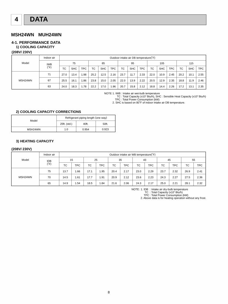
8
DATA4
Model Refrigerant piping length (one way)
1.0
25ft. (std.)
0.954
40ft.
0.923
50ft.
MSH24WN
2) COOLING CAPACITY CORRECTIONS
3) HEATING CAPACITY
(208V/ 230V)
Model
Indoor air Outdoor intake air WB temperature(˚F)
75
70
65
TC
13.7
14.5
14.9
TPC
1.66
1.61
1.54
TC
17.1
17.7
18.5
TPC
1.95
1.91
1.84
TC
20.4
20.9
21.6
TPC
2.17
2.12
2.06
TC
23.0
23.6
24.3
TPC
2.29
2.23
2.17
TC
23.7
24.3
25.0
TPC
2.32
2.27
2.21
TC
26.9
27.5
28.1
TPC
2.41
2.36
2.32
IDB(˚F)
15 25 35 43 45 55
MSH24WN
NOTE: 1. IDB : Intake air dry-bulb temperatureTC : Total Capacity (x103 Btu/h)
TPC : Total Power Consumption (kW)2. Above data is for heating operation without any frost.
4-1. PERFORMANCE DATA1) COOLING CAPACITY
MSH24WN MUH24WN
Model
Indoor air Outdoor intake air DB temperature(˚F)
71
67
63
TC
27.0
25.5
24.0
SHC
13.4
16.1
18.3
TPC
1.98
1.86
1.78
TC
25.2
23.8
22.2
SHC
12.5
15.0
17.0
TPC
2.16
2.05
1.96
TC
23.7
22.0
20.7
SHC
11.7
13.9
15.8
TPC
2.33
2.22
2.12
TC
22.0
20.5
18.8
SHC
10.9
12.9
14.4
TPC
2.45
2.35
2.26
TC
20.2
18.8
17.2
SHC
10.1
11.9
13.1
TPC
2.55
2.46
2.35
IWB(˚F)
75 85 95 105 115
MSH24WN
(208V/ 230V)
NOTE 1. IWB : Intake air wet-bulb temperatureTC : Total Capacity (x103 Btu/h), SHC : Sensible Heat Capacity (x103 Btu/h)
TPC : Total Power Consumption (kW) 2. SHC is based on 80˚F of indoor intake air DB temperature.
OB310--1.qxp 04.1.13 9:47 AM Page 8
9
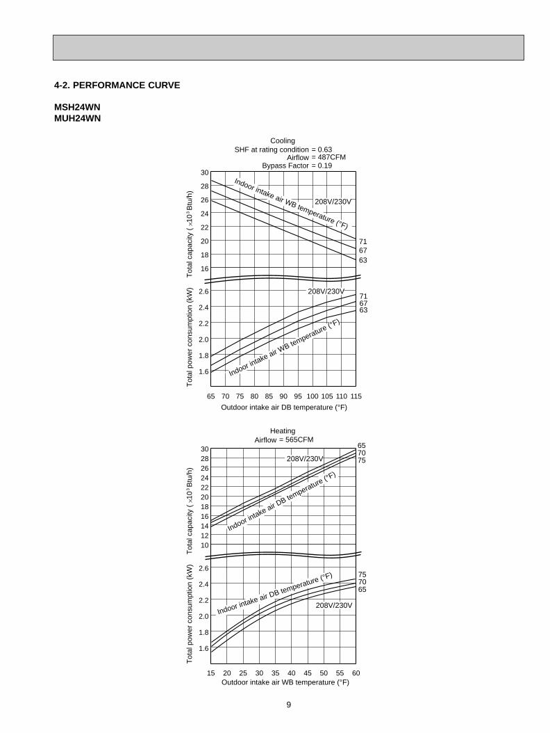
4-2. PERFORMANCE CURVE
MSH24WN MUH24WN
16
18
20
22
24
26
28
30
65 70 75 80 85 90 95 100 105 110 115
1.6
1.8
2.0
2.2
2.4
2.6
15 20 25 30 35 40 45 50 55 60
1.6
1.8
2.0
2.2
2.4
2.6
1012141618202224262830
716763
716763
657075
757065
Tot
al p
ower
con
sum
ptio
n (k
W)
Tot
al c
apac
ity (
10
Btu
/h)
Outdoor intake air DB temperature (°F)
Indoor intake air W
B temperature (°F)
Indoor intake air WB temperature (°F)
CoolingSHF at rating condition = 0.63
= 487CFM= 0.19
AirflowBypass Factor
Tot
al p
ower
con
sum
ptio
n (k
W)
Tot
al c
apac
ity (
10
Btu
/h)
Outdoor intake air WB temperature (°F)
Indoor intake air D
B temperature (°F)
Indoor intake air DB temperature (°F)
Heating= 565CFMAirflow
208V/230V
208V/230V
208V/230V
208V/230V
OB310--1.qxp 04.1.13 9:47 AM Page 9
10
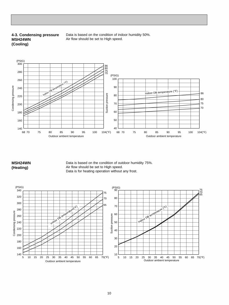
Data is based on the condition of indoor humidity 50%.Air flow should be set to High speed.
4-3. Condensing pressureMSH24WN(Cooling)
Data is based on the condition of outdoor humidity 75%.Air flow should be set to High speed.Data is for heating operation without any frost.
MSH24WN(Heating)
68 70 75 80 85 90 95 100 104(°F)
40
50
60
70
80
90
100
Suc
tion
pres
sure
Outdoor ambient temperature
68 70 75 80 85 90 95 100 104(°F)140
160
180
200
220
240
260
280
300(PSIG)
Con
dens
ing
pres
sure
Outdoor ambient temperature
Indoor DB temperature (°F
)
86807570
Indoor DB temperature (°F)
(PSIG)
86
80
75
70
5 10 15 20 25 30 35 40 45 50 55 60 65 70(°F)140
160
180
200
220
240
260
280
300
320
340
Indoor DB te
mperature(°F)
75 7065
75
70
65
(PSIG)
Con
dens
ing
pres
sure
Outdoor ambient temperature
(PSIG)
Suc
tion
pres
sure
Outdoor ambient temperature5 10 15 20 25 30 35 40 45 50 55 60 65 70(°F)
10
20
30
40
50
60
70
80
90
Indoor DB temperature (°F
)
OB310--1.qxp 04.1.13 9:47 AM Page 10
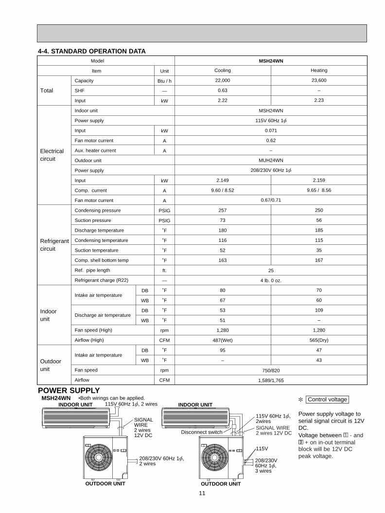
4-4. STANDARD OPERATION DATA
11
Capacity
SHF
Input
Indoor unit
Power supply
Input
Fan motor current
Aux. heater current
Outdoor unit
Power supply
Input
Comp. current
Fan motor current
Condensing pressure
Suction pressure
Discharge temperature
Condensing temperature
Suction temperature
Comp. shell bottom temp
Ref. pipe length
Refrigerant charge (R22)
Intake air temperature
Discharge air temperature
Fan speed (High)
Airflow (High)
Intake air temperature
Fan speed
Airflow
Unit
Btu / h
—
kW
kW
A
A
kW
A
A
PSIG
PSIG
˚F
˚F
˚F
˚F
ft.
—
˚F
˚F
˚F
˚F
rpm
CFM
˚F
˚F
rpm
CFM
Heating
23,600
–
2.23
2.159
9.65 / 8.56
250
56
185
115
35
167
70
60
109
–
1,280
565(Dry)
47
43
DB
WB
DB
WB
DB
WB
Item
Model
Total
Electricalcircuit
Refrigerantcircuit
Indoorunit
Outdoorunit
Cooling
22,000
0.63
2.22
2.149
9.60 / 8.52
257
73
180
116
52
163
80
67
53
51
1,280
487(Wet)
95
–
MSH24WN
115V 60Hz 1[
0.071
0.62
–
MUH24WN
208/230V 60Hz 1[
0.67/0.71
25
4 lb. 0 oz.
750/820
1,589/1,765
MSH24WN
POWER SUPPLY Control voltage
Power supply voltage toserial signal circuit is 12VDC.Voltage between 11 - and33 + on in-out terminalblock will be 12V DCpeak voltage.
MSH24WNINDOOR UNIT
OUTDOOR UNIT
115V 60Hz 1[, 2 wires
208/230V 60Hz 1[, 2 wires
SIGNALWIRE2 wires12V DC
INDOOR UNIT
OUTDOOR UNIT
208/230V60Hz 1[, 3 wires
115V 60Hz 1[, 2wiresSIGNAL WIRE2 wires 12V DC
•Both wirings can be applied.
115V
Disconnect switch
OB310--1.qxp 04.1.13 9:47 AM Page 11
12
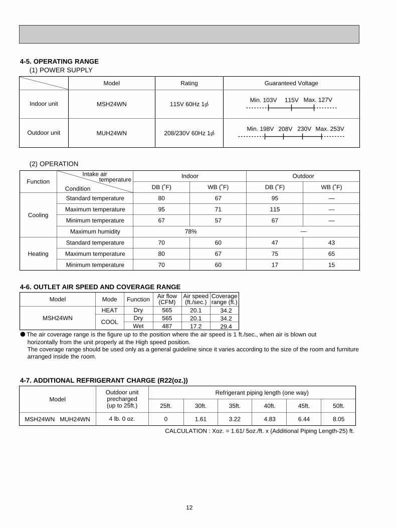
4-5. OPERATING RANGE(1) POWER SUPPLY
Indoor unit
Outdoor unit
Rating
115V 60Hz 1[
208/230V 60Hz 1[
Guaranteed Voltage
MSH24WN
MUH24WN
Model
Min. 103V Max. 127V 115V
Min. 198V Max. 253V208V 230V
(2) OPERATION
78% —
Function
Cooling
Heating
Standard temperature
Maximum temperature
Minimum temperature
Maximum humidity
Standard temperature
Maximum temperature
Minimum temperature
DB (˚F)
80
95
67
70
80
70
WB (˚F)
67
71
57
60
67
60
Indoor
DB (˚F)
95
115
67
47
75
17
WB (˚F)
—
—
—
43
65
15
Outdoor
Condition
Intake air temperature
4-6. OUTLET AIR SPEED AND COVERAGE RANGE
Model
MSH24WN
Mode
HEAT
COOL
565565487
Air flow(CFM)
Air speed(ft./sec.)
Coveragerange (ft.)Function
DryDryWet
20.120.117.2
34.234.229.4
4-7. ADDITIONAL REFRIGERANT CHARGE (R22(oz.))
MSH24WN MUH24WN
Outdoor unitprecharged(up to 25ft.)
4 lb. 0 oz.
25ft.
0
30ft.
1.61
35ft.
3.22
Refrigerant piping length (one way)
40ft.
4.83
45ft.
6.44
50ft.
8.05
Model
CALCULATION : Xoz. = 1.61/ 5oz./ft. x (Additional Piping Length-25) ft.
The air coverage range is the figure up to the position where the air speed is 1 ft./sec., when air is blown out horizontally from the unit properly at the High speed position.The coverage range should be used only as a general guideline since it varies according to the size of the room and furniturearranged inside the room.
OB310--1.qxp 04.1.13 9:47 AM Page 12
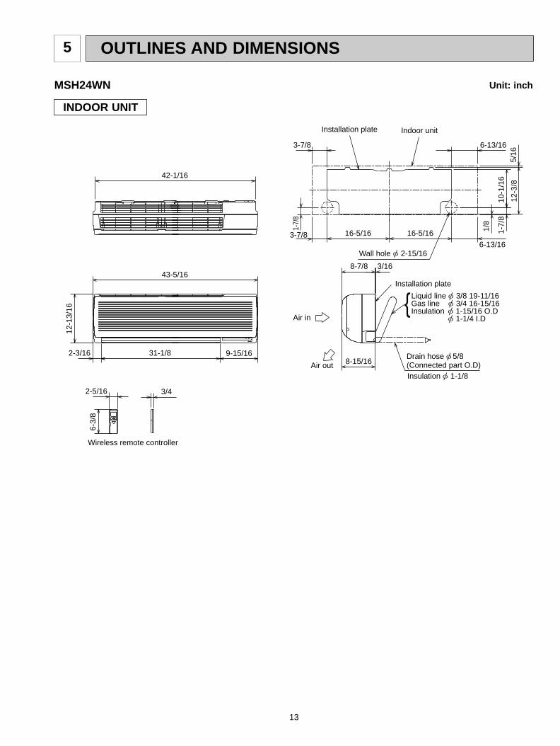
13
OUTLINES AND DIMENSIONS5
MSH24WN
INDOOR UNIT
Unit: inch6-
3/8
3/42-5/16
1-7/
8
5/16
12-3
/8
10-1
/16
1-7/
8
1/8
3-7/8
3-7/8
6-13/16
6-13/16
16-5/16 16-5/16
3/168-7/8
8-15/169-15/1631-1/82-3/16
42-1/16
43-5/16
12-1
3/16
Air out
Air in
Insulation [ 1-1/8
Drain hose [ 5/8(Connected part O.D)
Liquid line [ 3/8 19-11/16Gas line [ 3/4 16-15/16Insulation [ 1-15/16 O.D
[ 1-1/4 I.D
Installation plate
Wall hole [ 2-15/16
Wireless remote controller
Installation plate Indoor unit
OB310--1.qxp 04.1.13 9:47 AM Page 13
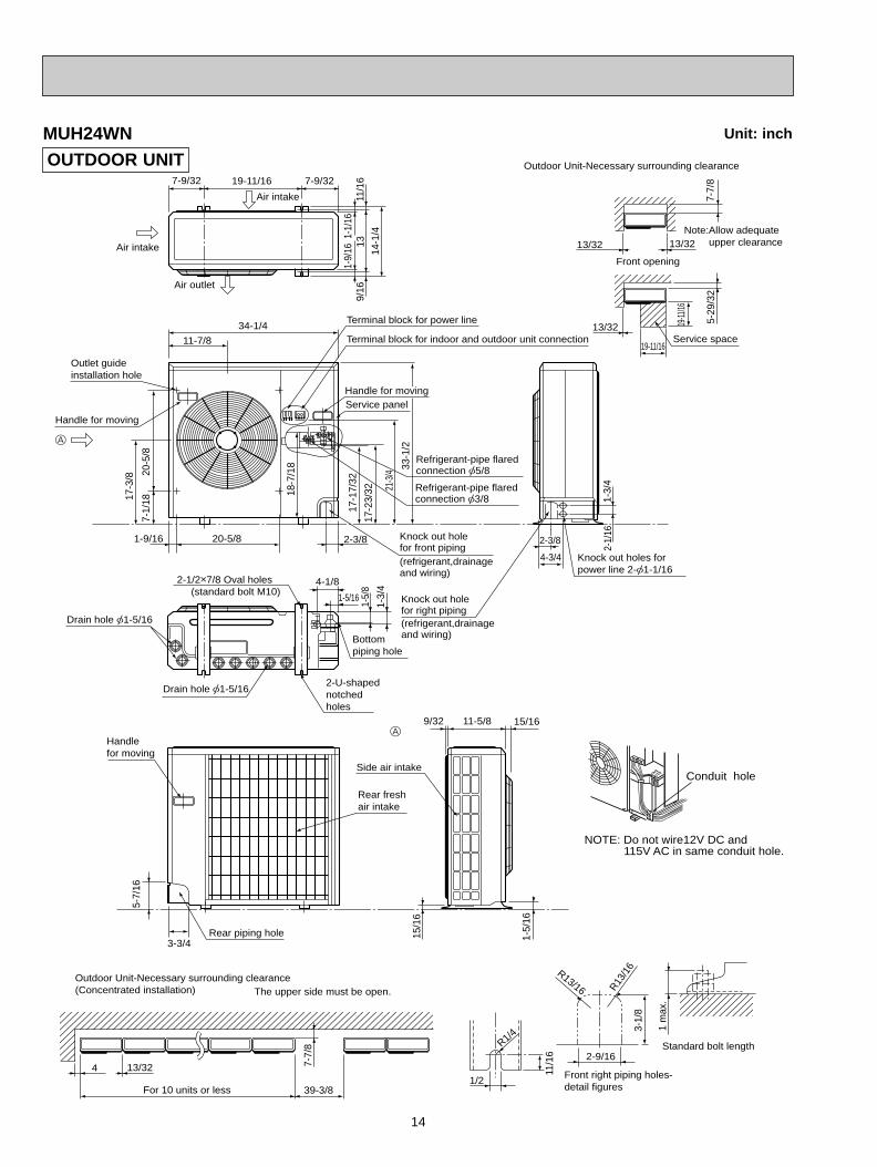
14
MUH24WNOUTDOOR UNIT
4 13/32
39-3/8For 10 units or less
7-7/
8
Outdoor Unit-Necessary surrounding clearance(Concentrated installation) The upper side must be open.
Outdoor Unit-Necessary surrounding clearance
7-7/
8
13/32
13/32
13/32Note:Allow adequate upper clearance
5-29
/32
19-11
/16
19-11/16Service space
Front opening
R13/16 R13/1
6
1 m
ax.
Standard bolt length2-9/16
Front right piping holes-detail figures
3-1/
8
11/1
6
1/2
R1/4
15/1
6
1-5/
16
Side air intake
9/32 15/1611-5/8
Outlet guideinstallation hole
11-7/8
Air intake
Air intake
Air outlet
34-1/4
7-9/32 7-9/3219-11/16
13
14-1
/4
11/1
69/
161-
9/16
1-1/
16Terminal block for indoor and outdoor unit connection
Terminal block for power line
Handle for moving
7-1/
1820
-5/8
17-3
/8
17-1
7/32
17-2
3/3218
-7/1
8
21-3
/4
33-1
/2
1-9/16 2-3/820-5/8
Service panel
Refrigerant-pipe flaredconnection [5/8
Refrigerant-pipe flaredconnection [3/8
Knock out holefor front piping(refrigerant,drainageand wiring)
1-5/
8
1-3/
44-1/8
1-5/16
Bottompiping hole
2-U-shapednotchedholes
Drain hole [1-5/16
Drain hole [1-5/16
2-1/2o7/8 Oval holes(standard bolt M10)
Handle for moving
A
Handlefor moving
5-7/
16
3-3/4Rear piping hole
Rear freshair intake
A
Knock out holefor right piping(refrigerant,drainage and wiring)
4-3/4
1-3/
42-
1/16
Knock out holes forpower line 2-[1-1/16
2-3/8
NOTE: Do not wire12V DC and 115V AC in same conduit hole.
Conduit hole
Unit: inch
OB310--1.qxp 04.1.13 9:47 AM Page 14
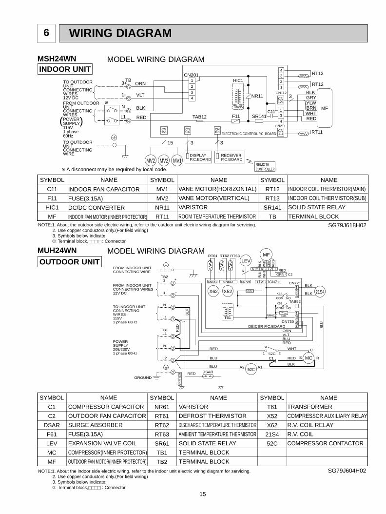
15
WIRING DIAGRAM6
MSH24WN
MUH24WN
MODEL WIRING DIAGRAM
MODEL WIRING DIAGRAM
INDOOR UNIT
OUTDOOR UNIT
TAB12POWER
FROM OUTDOORUNITCONNECTINGWIRES
TO OUTDOORUNITCONNECTINGWIRE
SUPPLY115V1 phase60Hz
CN201 RT13
121CN
CN211
CN112
TO OUTDOORUNITCONNECTINGWIRES12V DC
3
F11
VLT1-
3+
15
3
REMOTECONTROLLER
MV2 MV2 MV1
BLKGRY
TRANS
HIC1
C11N
L1
BLK
ORN
WHTBRNYLW
RED
ELECTRONIC CONTROL P.C. BOARD
NR11
RED
MF
RT12
CN151
CN101
3
DISPLAY P.C.BOARD
RECEIVER P.C.BOARD
CN102
SR141134
4321
RT11111CN
1
2
3
4
TB
w
( )
w A disconnect may be required by local code.
DEICER P.C.BOARD
FROM INDOOR UNITCONNECTING WIRES12V DC
TO INDOOR UNITCONNECTINGWIRES115V1 phase 60Hz
BLK
RE
D
FROM INDOOR UNITCONNECTING WIRE
BLK
BLK
RED
REDGROUND
GRN/
YLW
REDBLUVLT
BLU
7
POWERSUPPLY208/230V1 phase 60Hz
BLK
WH
T
CN721
1 52C 2
REDC2ORN
CN730
A2 A1BLU52C
WHT
C1 RED
BLK
S
C
R
NR61
53
BLU
T61
CN661
RT61
X52X62 X62
123
21S4
ORN
SR61
COM NO
F61
TAB52X52
1
CN711CN724CN662
6
MFRT62 RT63
1 2 3
2 1
BLK WH
TO
RN
RE
D3456
LEV
NOCOM
TB23
TB1L1
N
L2
1
N
L1
DSAR
-
+
MC
NOTE:1. About the outdoor side electric wiring, refer to the outdoor unit electric wiring diagram for servicing.2. Use copper conductors only.(For field wiring)3. Symbols below indicate;
: Terminal block, : Connector
SYMBOL
RT12
RT13
SR141
TB
SYMBOL
MV1
MV2
NR11
RT11
SYMBOL
C11
F11
HIC1
MF
NAME NAME NAME
INDOOR FAN CAPACITOR
FUSE(3.15A)
DC/DC CONVERTER
INDOOR FAN MOTOR (INNER PROTECTOR)
VANE MOTOR(HORIZONTAL)
VANE MOTOR(VERTICAL)
VARISTOR
ROOM TEMPERATURE THERMISTOR
INDOOR COIL THERMISTOR(MAIN)
INDOOR COIL THERMISTOR(SUB)
SOLID STATE RELAY
TERMINAL BLOCK
SG79J618H02
SYMBOL
T61
X52
X62
21S4
52C
SYMBOL
NR61
RT61
RT62
RT63
SR61
TB1
TB2
SYMBOL
C1
C2
DSAR
F61
LEV
MC
MF
NAME NAME NAME
COMPRESSOR CAPACITOR
OUTDOOR FAN CAPACITOR
SURGE ABSORBER
FUSE(3.15A)
EXPANSION VALVE COIL
COMPRESSOR(INNER PROTECTOR)
OUTDOOR FAN MOTOR(INNER PROTECTOR)
VARISTOR
DEFROST THERMISTOR
DISCHARGE TEMPERATURE THERMISTOR
AMBIENT TEMPERATURE THERMISTOR
SOLID STATE RELAY
TERMINAL BLOCK
TERMINAL BLOCK
TRANSFORMER
COMPRESSOR AUXILIARY RELAY
R.V. COIL RELAY
R.V. COIL
COMPRESSOR CONTACTOR
SG79J604H02NOTE:1. About the indoor side electric wiring, refer to the indoor unit electric wiring diagram for servicing.2. Use copper conductors only.(For field wiring)3. Symbols below indicate;
: Terminal block, : Connector
OB310--1.qxp 04.1.13 9:47 AM Page 15
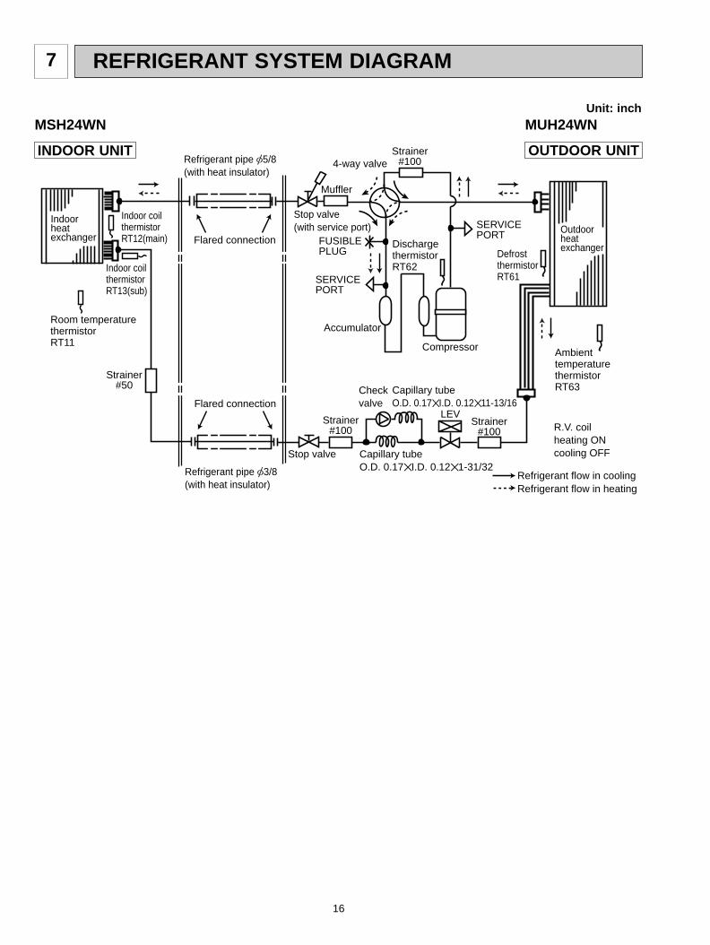
16
REFRIGERANT SYSTEM DIAGRAM7
MSH24WN MUH24WN
INDOOR UNIT OUTDOOR UNIT
Indoorheatexchanger
Outdoorheatexchanger
Flared connection
Room temperaturethermistorRT11
Indoor coil thermistorRT13(sub)
DefrostthermistorRT61
DischargethermistorRT62
Flared connection
Stop valve
Stop valve(with service port)
Capillary tubeO.D. 0.17I.D. 0.121-31/32
Refrigerant flow in cooling
Compressor
Muffler
4-way valve
Refrigerant flow in heating
Refrigerant pipe [5/8(with heat insulator)
Refrigerant pipe [3/8(with heat insulator)
Indoor coil thermistorRT12(main)
LEVR.V. coilheating ONcooling OFF
Strainer#100
Check valve
Accumulator
SERVICEPORT
SERVICEPORT
FUSIBLEPLUG
Ambient temperaturethermistorRT63Capillary tube
O.D. 0.17I.D. 0.1211-13/16
Strainer#100
Strainer#100
Strainer#50
Unit: inch
OB310--1.qxp 04.1.13 9:47 AM Page 16
17
MICROPROCESSOR CONTROL8
lighted
not lighted
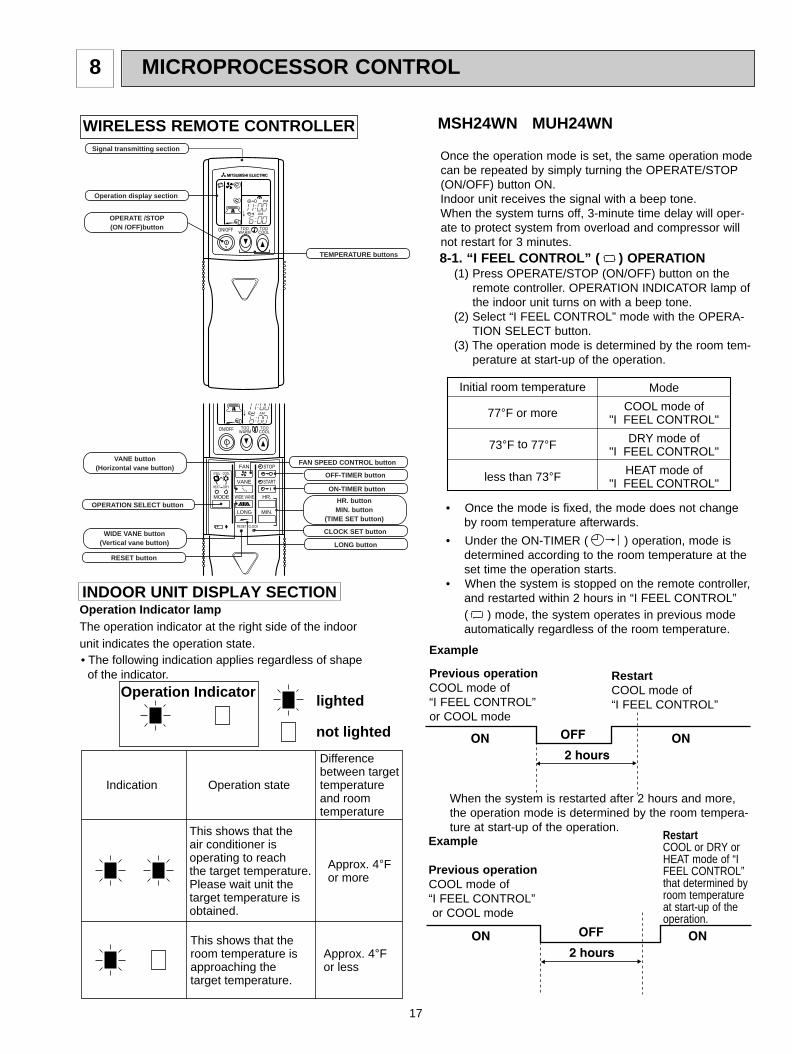
Approx. 4-F or more
Difference between target temperature and room temperature
Approx. 4-F or less
This shows that the air conditioner is operating to reach the target temperature.Please wait unit the target temperature is obtained.
This shows that the room temperature is approaching the target temperature.
Operation stateIndication
Operation Indicator
Operation Indicator lampThe operation indicator at the right side of the indoor unit indicates the operation state.
INDOOR UNIT DISPLAY SECTION
• The following indication applies regardless of shape of the indicator.
WIRELESS REMOTE CONTROLLER
Mode
COOL mode of"I FEEL CONTROL"
DRY mode of"I FEEL CONTROL"
HEAT mode of"I FEEL CONTROL"
Initial room temperature
77-F or more
73-F to 77-F
less than 73-F
MSH24WN MUH24WN
ON/OFF
FAN
TOOWARM
TOOCOOL
VANE
MODE
STOP
START
HR.
MIN.
WIDE VANE
LONG
I FEEL COOL
HEAT DRY
PMCLOCK
AM
RESET CLOCK
OPERATION SELECT button
FAN SPEED CONTROL button
OFF-TIMER button
HR. buttonMIN. button
(TIME SET button)
ON-TIMER button
RESET button
VANE button(Horizontal vane button)
CLOCK SET button
LONG button
WIDE VANE button(Vertical vane button)
ON/OFF TOOCOOL
PM
AM
TOOWARM
Signal transmitting section
Operation display section
OPERATE /STOP(ON /OFF)button
TEMPERATURE buttons
Once the operation mode is set, the same operation modecan be repeated by simply turning the OPERATE/STOP(ON/OFF) button ON.Indoor unit receives the signal with a beep tone.When the system turns off, 3-minute time delay will oper-ate to protect system from overload and compressor willnot restart for 3 minutes.8-1. “I FEEL CONTROL” ( ) OPERATION
(1) Press OPERATE/STOP (ON/OFF) button on theremote controller. OPERATION INDICATOR lamp ofthe indoor unit turns on with a beep tone.
(2) Select “I FEEL CONTROL” mode with the OPERA-TION SELECT button.
(3) The operation mode is determined by the room tem-perature at start-up of the operation.
Example
Previous operationCOOL mode of “I FEEL CONTROL”or COOL mode
• Once the mode is fixed, the mode does not changeby room temperature afterwards.
• Under the ON-TIMER ( ) operation, mode isdetermined according to the room temperature at theset time the operation starts.
• When the system is stopped on the remote controller,and restarted within 2 hours in “I FEEL CONTROL”( ) mode, the system operates in previous modeautomatically regardless of the room temperature.
Example
Previous operationCOOL mode of “I FEEL CONTROL”or COOL mode
When the system is restarted after 2 hours and more,the operation mode is determined by the room tempera-ture at start-up of the operation.
RestartCOOL mode of “I FEEL CONTROL”
RestartCOOL or DRY orHEAT mode of “IFEEL CONTROL”that determined byroom temperatureat start-up of theoperation.
OB310--1.qxp 04.1.13 9:47 AM Page 17
18
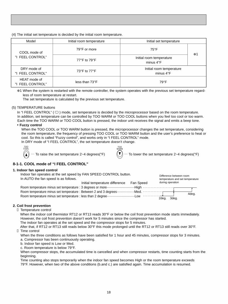
Model
COOL mode of"I FEEL CONTROL"
DRY mode of"I FEEL CONTROL"
HEAT mode of"I FEEL CONTROL"
Initial room temperature Initial set temperature
79-F
79-F or more
77-F to 79-F
less than 73-F
73-F to 77-F
75-F
Initial room temperatureminus 4-F
Initial room temperatureminus 4-F
1
(4) The initial set temperature is decided by the initial room temperature.
1 When the system is restarted with the remote controller, the system operates with the previous set temperature regard-less of room temperature at restart.The set temperature is calculated by the previous set temperature.
(5) TEMPERATURE buttonsIn “I FEEL CONTROL” ( ) mode, set temperature is decided by the microprocessor based on the room temperature.In addition, set temperature can be controlled by TOO WARM or TOO COOL buttons when you feel too cool or too warm.Each time the TOO WARM or TOO COOL button is pressed, the indoor unit receives the signal and emits a beep tone.• Fuzzy control
When the TOO COOL or TOO WARM button is pressed, the microprocessor changes the set temperature, consideringthe room temperature, the frequency of pressing TOO COOL or TOO WARM button and the user’s preference to heat orcool. So this is called “Fuzzy control”, and works only in “I FEEL CONTROL” mode.In DRY mode of “I FEEL CONTROL”, the set temperature doesn’t change.
… To raise the set temperature 2~4 degrees(°F) … To lower the set temperature 2~4 degrees(°F)
TOOCOOL
TOOWARM
1. Indoor fan speed controlIndoor fan operates at the set speed by FAN SPEED CONTROL button.In AUTO the fan speed is as follows.
Initial temperature difference Fan SpeedRoom temperature minus set temperature : 3 degrees or more·····························HighRoom temperature minus set temperature : Between 2 and 3 degrees··················Med.Room temperature minus set temperature : less than 2 degree·····························Low
8-1-1. COOL mode of “I FEEL CONTROL”
Difference between roomtemperature and set temperatureduring operation
2deg. 3deg.4deg.
2. Coil frost prevention① Temperature control
When the indoor coil thermistor RT12 or RT13 reads 30°F or below the coil frost prevention mode starts immediately.However, the coil frost prevention doesn’t work for 5 minutes since the compressor has started.The indoor fan operates at the set speed and the compressor stops for 5 minutes.After that, if RT12 or RT13 still reads below 30°F this mode prolonged until the RT12 or RT13 still reads over 30°F.
② Time controlWhen the three conditions as follows have been satisfied for 1 hour and 45 minutes, compressor stops for 3 minutes.a. Compressor has been continuously operating.b. Indoor fan speed is Low or Med.c. Room temperature is below 79°F.When compressor stops, the accumulated time is cancelled and when compressor restarts, time counting starts from the beginning.Time counting also stops temporarily when the indoor fan speed becomes High or the room temperature exceeds 79°F. However, when two of the above conditions (b.and c.) are satisfied again. Time accumulation is resumed.
OB310--1.qxp 04.1.13 9:47 AM Page 18
19
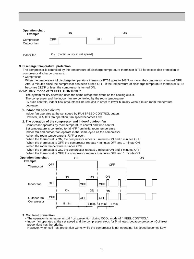
Compressor Outdoor fan
OFF
ON
(continuously at set speed)Indoor fan ON
ON
OFF
Operation chartExample
3. Discharge temperature protectionThe compressor is controlled by the temperature of discharge temperature thermistor RT62 for excess rise protection ofcompressor discharge pressure.• Compressor
When the temperature of discharge temperature thermistor RT62 goes to 248°F or more, the compressor is turned OFF.After 3 minutes since the compressor has been turned OFF, if the temperature of discharge temperature thermistor RT62becomes 212°F or less, the compressor is turned ON.
8-1-2. DRY mode of “I FEEL CONTROL”The system for dry operation uses the same refrigerant circuit as the cooling circuit.The compressor and the indoor fan are controlled by the room temperature.By such controls, indoor flow amounts will be reduced in order to lower humidity without much room temperature decrease.
2. The operation of the compressor and indoor/ outdoor fanCompressor operates by room temperature control and time control.Set temperature is controlled to fall 4°F from initial room temperature.Indoor fan and outdoor fan operate in the same cycle as the compressor.•When the room temperature is 73°F or over:When the thermostat is ON, the compressor repeats 8 minutes ON and 3 minutes OFF.When the thermostat is OFF, the compressor repeats 4 minutes OFF and 1 minute ON.
•When the room temperature is under 73°F.When the thermostat is ON, the compressor repeats 2 minutes ON and 3 minutes OFF.When the thermostat is OFF, the compressor repeats 4 minutes OFF and 1 minute ON.
1. Indoor fan speed controlIndoor fan operates at the set speed by FAN SPEED CONTROL button.However, in AUTO fan operation, fan speed becomes Low.
Operation time chartExample
Thermostat
Indoor fan
Outdoor fan Compressor
ON
8 min. 1 min.4 min.3 min.
ON
OFF
OFF
OFF
OFF
OFF
ONONON
ONONON
OFF
OFF
OFF
3. Coil frost prevention • The operation is as same as coil frost prevention during COOL mode of “I FEEL CONTROL”.• Indoor fan operates at the set speed and the compressor stops for 5 minutes, because protection(Coil frost
prevention) has the priority.However, when coil frost prevention works while the compressor is not operating, it’s speed becomes Low.
OB310--1.qxp 04.1.13 9:47 AM Page 19
20
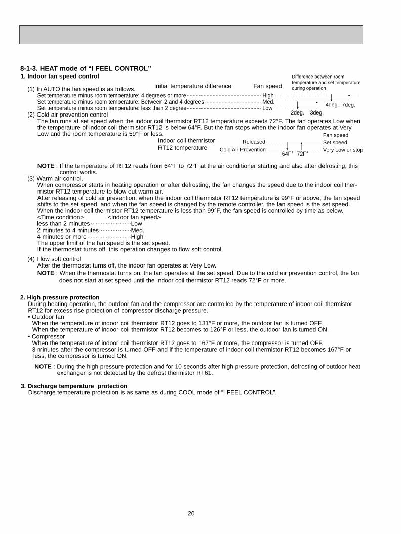
(4) Flow soft controlAfter the thermostat turns off, the indoor fan operates at Very Low.NOTE : When the thermostat turns on, the fan operates at the set speed. Due to the cold air prevention control, the fan
does not start at set speed until the indoor coil thermistor RT12 reads 72°F or more.
<Time condition> <Indoor fan speed>less than 2 minutes························Low2 minutes to 4 minutes···················Med.4 minutes or more··························HighThe upper limit of the fan speed is the set speed.If the thermostat turns off, this operation changes to flow soft control.
8-1-3. HEAT mode of “I FEEL CONTROL”1. Indoor fan speed control
(1) In AUTO the fan speed is as follows.Set temperature minus room temperature: 4 degrees or more················································· HighSet temperature minus room temperature: Between 2 and 4 degrees ····································· Med.Set temperature minus room temperature: less than 2 degree················································· Low
(2) Cold air prevention controlThe fan runs at set speed when the indoor coil thermistor RT12 temperature exceeds 72°F. The fan operates Low whenthe temperature of indoor coil thermistor RT12 is below 64°F. But the fan stops when the indoor fan operates at VeryLow and the room temperature is 59°F or less.
NOTE : If the temperature of RT12 reads from 64°F to 72°F at the air conditioner starting and also after defrosting, thiscontrol works.
(3) Warm air control.When compressor starts in heating operation or after defrosting, the fan changes the speed due to the indoor coil ther-mistor RT12 temperature to blow out warm air.After releasing of cold air prevention, when the indoor coil thermistor RT12 temperature is 99°F or above, the fan speedshifts to the set speed, and when the fan speed is changed by the remote controller, the fan speed is the set speed.When the indoor coil thermistor RT12 temperature is less than 99°F, the fan speed is controlled by time as below.
Difference between roomtemperature and set temperatureduring operation
2deg. 3deg.7deg.4deg.
Initial temperature difference Fan speed
Indoor coil thermistorRT12 temperature
Released
Cold Air Prevention64F- 72F-
Fan speed Set speedVery Low or stop
NOTE : During the high pressure protection and for 10 seconds after high pressure protection, defrosting of outdoor heatexchanger is not detected by the defrost thermistor RT61.
3. Discharge temperature protectionDischarge temperature protection is as same as during COOL mode of “I FEEL CONTROL”.
• CompressorWhen the temperature of indoor coil thermistor RT12 goes to 167°F or more, the compressor is turned OFF.3 minutes after the compressor is turned OFF and if the temperature of indoor coil thermistor RT12 becomes 167°F or less, the compressor is turned ON.
2. High pressure protectionDuring heating operation, the outdoor fan and the compressor are controlled by the temperature of indoor coil thermistorRT12 for excess rise protection of compressor discharge pressure.• Outdoor fan
When the temperature of indoor coil thermistor RT12 goes to 131°F or more, the outdoor fan is turned OFF.When the temperature of indoor coil thermistor RT12 becomes to 126°F or less, the outdoor fan is turned ON.
OB310--1.qxp 04.1.13 9:47 AM Page 20
21
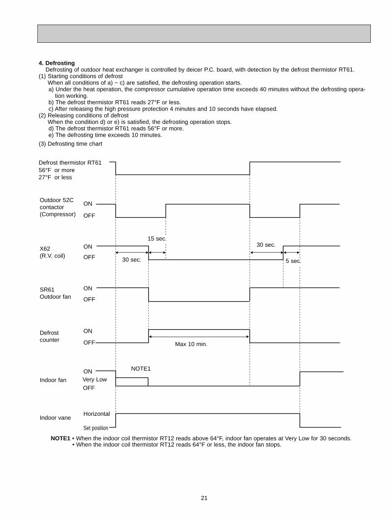
NOTE1 • When the indoor coil thermistor RT12 reads above 64°F, indoor fan operates at Very Low for 30 seconds.• When the indoor coil thermistor RT12 reads 64°F or less, the indoor fan stops.
(3) Defrosting time chart
Defrost thermistor RT6156°F or more27°F or less
Outdoor 52Ccontactor(Compressor)
X62(R.V. coil)
SR61Outdoor fan
Defrost counter
Indoor fan
Indoor vane
ON
OFF
ON
OFF
ON
OFF
ON
OFF
ON
OFF
Horizontal
Set position
Max 10 min.
30 sec.
15 sec.30 sec.
5 sec.
NOTE1
4. DefrostingDefrosting of outdoor heat exchanger is controlled by deicer P.C. board, with detection by the defrost thermistor RT61.
(1) Starting conditions of defrost When all conditions of a) ~ c) are satisfied, the defrosting operation starts.a) Under the heat operation, the compressor cumulative operation time exceeds 40 minutes without the defrosting opera-
tion working.b) The defrost thermistor RT61 reads 27°F or less.c) After releasing the high pressure protection 4 minutes and 10 seconds have elapsed.
(2) Releasing conditions of defrost When the condition d) or e) is satisfied, the defrosting operation stops.d) The defrost thermistor RT61 reads 56°F or more.e) The defrosting time exceeds 10 minutes.
Very Low
OB310--1.qxp 04.1.13 9:47 AM Page 21
22
8-2. COOL ( ) OPERATION(1) Press OPERATE/STOP (ON/OFF) button.
OPERATION INDICATOR lamp of the indoor unit turns on with a beep tone.(2) Select COOL mode with the OPERATION SELECT
button.(3) Press TEMPERATURE buttons.
(TOO WARM or TOO COOL button) to select thedesired temperature.The setting range is 59 ~ 89°F. Indoor fan continues to operate regardless of
thermostat’s OFF-ON at set speed. Coil frost prevention is as same as COOL mode
of “I FEEL CONTROL”.
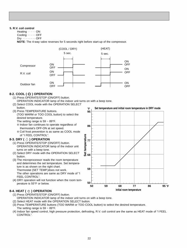
8-3. DRY ( ) OPERATION(1) Press OPERATE/STOP (ON/OFF) button.
OPERATION INDICATOR lamp of the indoor unitturns on with a beep tone.
(2) Select DRY mode with the OPERATION SELECTbutton.
(3) The microprocessor reads the room temperatureand determines the set temperature. Set tempera-ture is as shown on the right chart.Thermostat (SET TEMP.)does not work.The other operations are same as DRY mode of “IFEEL CONTROL”.
(4) DRY operation will not function when the room tem-perature is 55°F or below.
8-4. HEAT ( ) OPERATION(1) Press OPERATE/STOP (ON/OFF) button.
OPERATION INDICATOR lamp of the indoor unit turns on with a beep tone.(2) Select HEAT mode with the OPERATION SELECT button.(3) Press TEMPERATURE buttons (TOO WARM or TOO COOL button) to select the desired temperature.
The setting range is 59 ~ 89°F.(4) Indoor fan speed control, high pressure protection, defrosting, R.V. coil control are the same as HEAT mode of “I FEEL
CONTROL”.
5. R.V. coil controlHeating · · · · · ONCooling · · · · · OFFDry · · · · · · · · OFFNOTE: The 4-way valve reverses for 5 seconds right before start-up of the compressor.
95
86
77
68
5050 59 68 77 86 95
59
-F
-F
ONOFF
ONOFF
ONOFF
ONOFF
ONOFF
ONOFF
Compressor
R.V. coil
Outdoor fan
(COOL / DRY) (HEAT)
5 sec. 5 sec.
OB310--1.qxp 04.1.13 9:47 AM Page 22
23
High
Rotational frequency
High
time
Med.
Low
AUTO
Horizontal
1 2 3 4 5
Middle Downward Swing
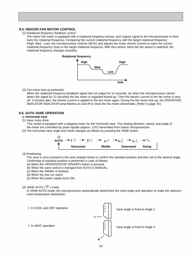
8-6. AUTO VANE OPERATION1. Horizontal vane(1) Vane motor drive
This model is equipped with a stepping motor for the horizontal vane. The rotating direction, speed, and angle of the motor are controlled by pulse signals (approx. 12V) transmitted from indoor microprocessor.
(2) The horizontal vane angle and mode changes as follows by pressing the VANE button.
8-5. INDOOR FAN MOTOR CONTROL(1) Rotational frequency feedback control
The indoor fan motor is equipped with a rotational frequency sensor, and outputs signal to the microprocessor to feedback the rotational frequency. Comparing the current rotational frequency with the target rotational frequency (High, Med., Low), the microprocessor controls SR141 and adjusts fan motor electric current to make the current rotational frequency close to the target rotational frequency. With this control, when the fan speed is switched, the rotational frequency changes smoothly.
(2) Fan motor lock-up protectionWhen the rotational frequency feedback signal has not output for 12 seconds, (or when the microprocessor cannot detect the signal for 12 seconds) the fan motor is regarded locked-up. Then the electric current to the fan motor is shut off. 3 minutes later, the electric current is applied to the fan motor again. During the fan motor lock-up, the OPERATION INDICATOR INDICATOR lamp flashes on and off to show the fan motor abnormality. (Refer to page 33.)
① In COOL and DRY operation
➁ In HEAT operation
Vane angle is fixed to Angle 1.
Vane angle is fixed to Angle 4.
(3) PositioningThe vane is once pressed to the vane stopper below to confirm the standard position and then set to the desired angle.Confirming of standard position is performed in case of follows.(a) When the OPERATE/STOP (ON/OFF) button is pressed.(b) When the vane control is changed from AUTO to MANUAL.(c) When the SWING is finished.(d) When the test run starts.(e) When the power supply turns ON.
(4) VANE AUTO ( ) modeIn VANE AUTO mode, the microprocessor automatically determines the vane angle and operation to make the optimum room-temperature distribution.
OB310--1.qxp 04.1.13 9:47 AM Page 23
24
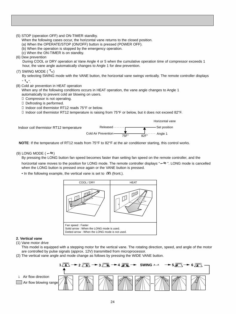
(9) LONG MODE ( )By pressing the LONG button fan speed becomes faster than setting fan speed on the remote controller, and the
horizontal vane moves to the position for LONG mode. The remote controller displays “ ”. LONG mode is cancelledwhen the LONG button is pressed once again or the VANE button is pressed.
• In the following example, the vertical vane is set to (front.).
COOL / DRY HEAT
Fan speed : FasterSolid arrow : When the LONG mode is used.Dotted arrow : When the LONG mode is not used.
Air flow direction
Air flow blowing range
61 2 3 4 5SWING
2. Vertical vane(1) Vane motor drive
This model is equipped with a stepping motor for the vertical vane. The rotating direction, speed, and angle of the motorare controlled by pulse signals (approx. 12V) transmitted from microprocessor.
(2) The vertical vane angle and mode change as follows by pressing the WIDE VANE button.
(5) STOP (operation OFF) and ON-TIMER standby.When the following cases occur, the horizontal vane returns to the closed position.(a) When the OPERATE/STOP (ON/OFF) button is pressed (POWER OFF).(b) When the operation is stopped by the emergency operation.(c) When the ON-TIMER is on standby.
(6) Dew preventionDuring COOL or DRY operation at Vane Angle 4 or 5 when the cumulative operation time of compressor exceeds 1hour, the vane angle automatically changes to Angle 1 for dew prevention.
(7) SWING MODE ( )By selecting SWING mode with the VANE button, the horizontal vane swings vertically. The remote controller displays
“ ”.(8) Cold air prevention in HEAT operation
When any of the following conditions occurs in HEAT operation, the vane angle changes to Angle 1 automatically to prevent cold air blowing on users.① Compressor is not operating.➁ Defrosting is performed.➂ Indoor coil thermistor RT12 reads 75°F or below.➃ Indoor coil thermistor RT12 temperature is raising from 75°F or below, but it does not exceed 82°F.
Released
Cold Air Prevention75F- 82F-
Angle 1
Horizontal vane
Set positionIndoor coil thermistor RT12 temperature
NOTE: If the temperature of RT12 reads from 75°F to 82°F at the air conditioner starting, this control works.
OB310--1.qxp 04.1.13 9:47 AM Page 24
25
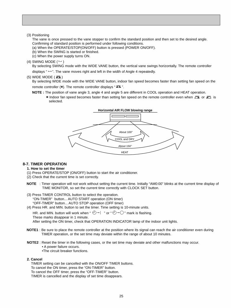
(3) PositioningThe vane is once pressed to the vane stopper to confirm the standard position and then set to the desired angle.Confirming of standard position is performed under following conditions.(a) When the OPERATE/STOP(ON/OFF) button is pressed (POWER ON/OFF).(b) When the SWING is started or finished.(c) When the power supply turns ON.
(4) SWING MODE ( )By selecting SWING mode with the WIDE VANE button, the vertical vane swings horizontally. The remote controller
displays “ ”. The vane moves right and left in the width of Angle 4 repeatedly.
(5) WIDE MODE ( )By selecting WIDE mode with the WIDE VANE button, indoor fan speed becomes faster than setting fan speed on the
remote controller (W). The remote controller displays “ ”.
NOTE : The position of vane angle 3, angle 4 and angle 5 are different in COOL operation and HEAT operation.W Indoor fan speed becomes faster than setting fan speed on the remote controller even when or is
selected.
COOL and DRY
HEAT
About 100-
About 150-
Horizontal AIR FLOW blowing range
8-7. TIMER OPERATION1. How to set the timer(1) Press OPERATE/STOP (ON/OFF) button to start the air conditioner.(2) Check that the current time is set correctly.
NOTE : Timer operation will not work without setting the current time. Initially “AM0:00” blinks at the current time display ofTIME MONITOR, so set the current time correctly with CLOCK SET button.
(3) Press TIMER CONTROL button to select the operation.“ON-TIMER” button... AUTO START operation (ON timer)“OFF-TIMER” button... AUTO STOP operation (OFF timer)
(4) Press HR. and MIN. button to set the timer. Time setting is 10-minute units.
HR. and MIN. button will work when “ ” or “ ” mark is flashing.These marks disappear in 1 minute.After setting the ON timer, check that OPERATION INDICATOR lamp of the indoor unit lights.
NOTE1 : Be sure to place the remote controller at the position where its signal can reach the air conditioner even duringTIMER operation, or the set time may deviate within the range of about 10 minutes.
NOTE2 : Reset the timer in the following cases, or the set time may deviate and other malfunctions may occur.• A power failure occurs.•The circuit breaker functions.
2. CancelTIMER setting can be cancelled with the ON/OFF TIMER buttons.To cancel the ON timer, press the “ON-TIMER” button.To cancel the OFF timer, press the “OFF-TIMER” button.TIMER is cancelled and the display of set time disappears.
OB310--1.qxp 04.1.13 9:47 AM Page 25
26
Press once <Cool>
Press again <Heat>
Press once again <Stop>
OPERATION INDICATOR lamp
• The following indication applies regardless of shape of the indicator.
EMERGENCY OPERATION switch
8-8. EMERGENCY-TEST OPERATIONIn case of test run operation or emergency operation, use the EMERGENCY OPERATION switch on the front of theindoor unit. Emergency operation is available when the remote controller is missing, has failed or the batteries of remotecontroller run down. The unit will start and the OPERATION INDICATOR lamp will light.The first 30 minutes of operation is the test run operation. This operation is for servicing. The indoor fan speed runs atHigh speed and the system is in continuous operation. (The thermostat is ON.)After 30 minutes of test run operation the system shifts to EMERGENCY COOL / HEAT MODE with a set temperature of75°F.The fan speed shifts to Med. speed.The coil frost prevention works even in emergency operation, and defrosting too.In the test run or emergency operation, the horizontal vane operates in VANE AUTO ( ) mode.Emergency operation continues until the EMERGENCY OPERATION switch is pressed once or twice or the unit receivesany signal from the remote controller. In case of latter normal operation will start.
NOTE : Do not press the EMERGENCY OPERATION switch during normal operation.
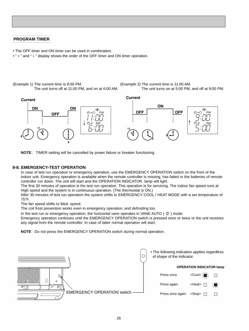
PROGRAM TIMER
(Example 1) The current time is 8:00 PM.The unit turns off at 11:00 PM, and on at 6:00 AM.
• The OFF timer and ON timer can be used in combination.• “ ” and “ ” display shows the order of the OFF timer and ON timer operation.
(Example 2) The current time is 11:00 AM.The unit turns on at 5:00 PM, and off at 9:00 PM.
NOTE : TIMER setting will be cancelled by power failure or breaker functioning.
PM
AM
PM
PM
OB310--1.qxp 04.1.13 9:47 AM Page 26
27
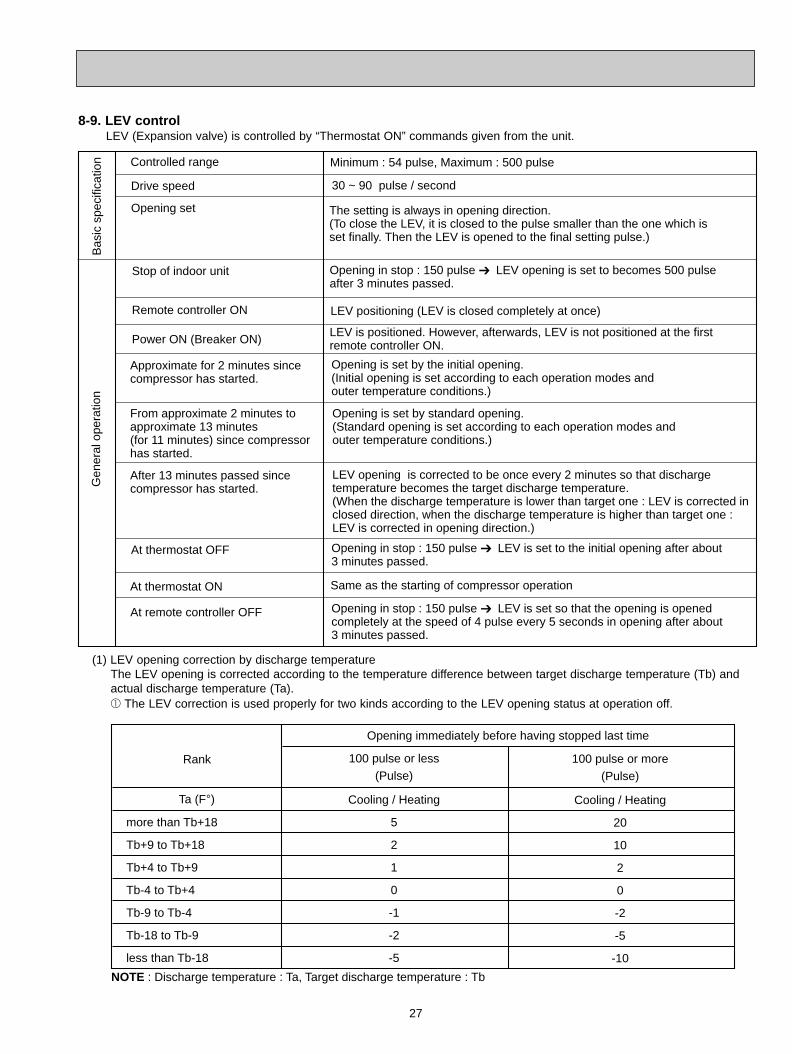
8-9. LEV controlLEV (Expansion valve) is controlled by “Thermostat ON” commands given from the unit.
Controlled range
Bas
ic s
peci
ficat
ion Minimum : 54 pulse, Maximum : 500 pulse
Drive speed 30 ~ 90 pulse / second
Opening set
Stop of indoor unit Opening in stop : 150 pulse LEV opening is set to becomes 500 pulse after 3 minutes passed.
Remote controller ON LEV positioning (LEV is closed completely at once)
Power ON (Breaker ON)LEV is positioned. However, afterwards, LEV is not positioned at the first remote controller ON.
Approximate for 2 minutes since compressor has started.
Opening is set by the initial opening. (Initial opening is set according to each operation modes and outer temperature conditions.)
From approximate 2 minutes to approximate 13 minutes (for 11 minutes) since compressorhas started.
Opening is set by standard opening. (Standard opening is set according to each operation modes and outer temperature conditions.)
After 13 minutes passed since compressor has started.
LEV opening is corrected to be once every 2 minutes so that discharge temperature becomes the target discharge temperature. (When the discharge temperature is lower than target one : LEV is corrected in closed direction, when the discharge temperature is higher than target one : LEV is corrected in opening direction.)
At thermostat OFF Opening in stop : 150 pulse LEV is set to the initial opening after about 3 minutes passed.
At thermostat ON Same as the starting of compressor operation
At remote controller OFF Opening in stop : 150 pulse LEV is set so that the opening is opened completely at the speed of 4 pulse every 5 seconds in opening after about 3 minutes passed.
Gen
eral
ope
ratio
n
The setting is always in opening direction.(To close the LEV, it is closed to the pulse smaller than the one which is set finally. Then the LEV is opened to the final setting pulse.)
(1) LEV opening correction by discharge temperatureThe LEV opening is corrected according to the temperature difference between target discharge temperature (Tb) and actual discharge temperature (Ta).1 The LEV correction is used properly for two kinds according to the LEV opening status at operation off.
Rank
Ta (F-)
more than Tb+18
Tb+9 to Tb+18
Tb+4 to Tb+9
Tb-4 to Tb+4
Tb-9 to Tb-4
Tb-18 to Tb-9
less than Tb-18
100 pulse or less(Pulse)
Cooling / Heating
5
2
1
0
-1
-2
-5
NOTE : Discharge temperature : Ta, Target discharge temperature : Tb
100 pulse or more(Pulse)
Cooling / Heating
20
10
2
0
-2
-5
-10
Opening immediately before having stopped last time
OB310--1.qxp 04.1.13 9:47 AM Page 27
28
2 When the temperature difference RT between indoor coil thermistor (main) RT12 and indoor coil thermistor (sub)RT13 in the indoor unit is 4deg. or more for a fixed time at cool or dry operation, the target discharge temperature is
changed. After the temperature is changed, when temperature difference RT is 6deg. or more, the target temperature is changed again. The LEV opening is controlled based on the changed target discharge temperature
and the temperature difference RT.
Ta (F-)
more than Tb+18
Tb+9 to Tb+18
Tb+4 to Tb+9
Tb-4 to Tb+4
Tb-9 to Tb-4
Tb-18 to Tb-9
less than Tb-18
less than 4deg.(Pulse)
20
10
2
0
-2
-5
-10
NOTE : Discharge temperature : Ta, Target discharge temperature : Tb
6deg. or more(Pulse)
60
20
10
0
-2
-5
-10
RT
4deg. or more and less than 6deg.(Pulse)
60
20
10
0
-2
-5
-10
The target discharge temperature (Tb) is set according to the operation mode or the unit status as follows.
Tb (-F)
HEAT
COOL (Normal)
COOL ( RT is less than 4deg., or RT is 4deg. or more and less than 6deg..)
COOL ( RT is 6deg. or more.)
NOTE : Target discharge temperature : Tb
180
176
144
136
Operation mode
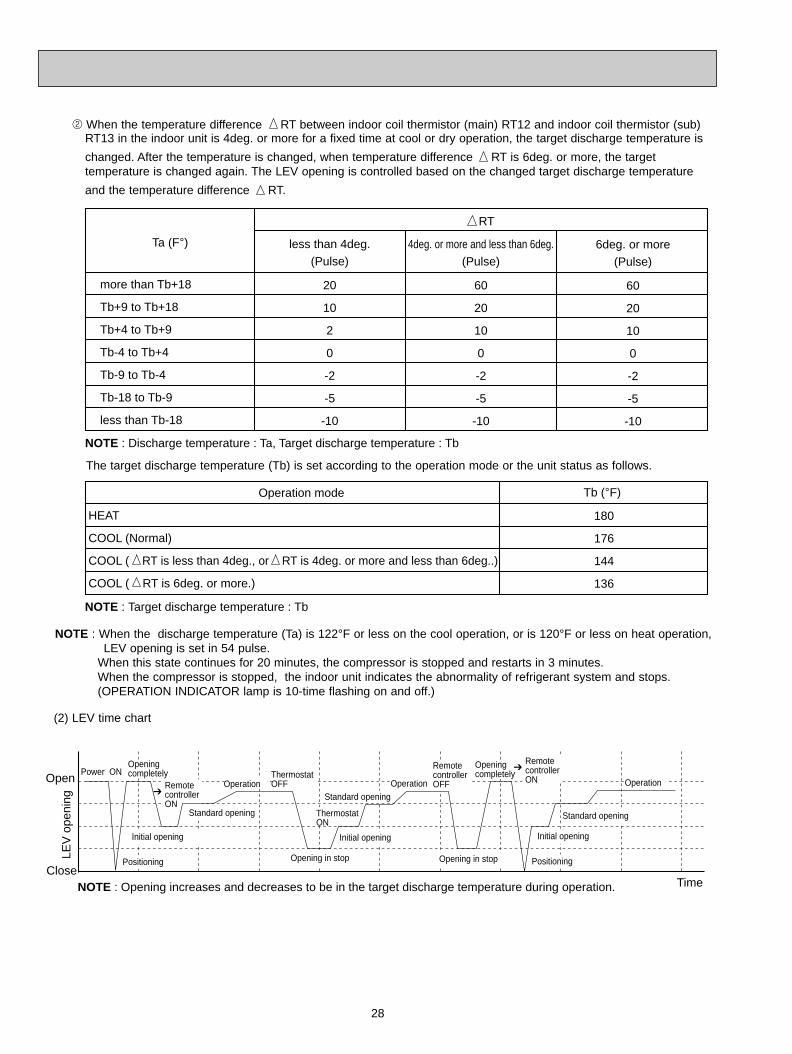
NOTE : Opening increases and decreases to be in the target discharge temperature during operation.
Opening completely
Positioning
Power ON
Initial opening
Standard opening
Remote controller ON
Operation
Thermostat OFF
Standard opening
Thermostat ON
Opening in stop
Initial opening
Operation
Opening in stop
Remote controller OFF
Opening completely
Remote controller ON
Positioning
Initial opening
Standard opening
Operation
Time
LEV
ope
ning
Open
Close
(2) LEV time chart
NOTE : When the discharge temperature (Ta) is 122°F or less on the cool operation, or is 120°F or less on heat operation, LEV opening is set in 54 pulse.
When this state continues for 20 minutes, the compressor is stopped and restarts in 3 minutes.When the compressor is stopped, the indoor unit indicates the abnormality of refrigerant system and stops.(OPERATION INDICATOR lamp is 10-time flashing on and off.)
OB310--1.qxp 04.1.13 9:47 AM Page 28
29
SERVICE FUNCTIONS9
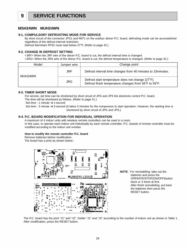
9-1. COMPULSORY DEFROSTING MODE FOR SERVICEBy short circuit of the connector JPG1 and R871 on the outdoor deicer P.C. board, defrosting mode can be accomplishedregardless of the defrost interval restriction.Defrost thermistor RT61 must read below 27°F. (Refer to page 42.)
MSH24WN MUH24WN
MUH24WN
Model Jumper wire Change point
JRF
JRG
Defrost interval time changes from 40 minutes to 15minutes.
Defrost start temperature does not change (27˚F).Defrost finish temperature changes from 56˚F to 59˚F.
9-2. CHANGE IN DEFROST SETTING<JRF> When the JRF wire of the deicer P.C. board is cut, the defrost interval time is changed. <JRG> When the JRG wire of the deicer P.C. board is cut, the defrost temperature is changed. (Refer to page 42.)
9-3. TIMER SHORT MODEFor service, set time can be shortened by short circuit of JPG and JPS the electronic control P.C. board.The time will be shortened as follows. (Refer to page 41.)Set time : 1 minute 1-secondSet time : 3 minute 3-second (It takes 3 minutes for the compressor to start operation. However, the starting time is
shortened by short circuit of JPG and JPS.)
The P.C. board has the print “J1” and “J2”. Solder “J1” and “J2” according to the number of indoor unit as shown in Table 1.After modification, press the RESET button.
9-4. P.C. BOARD MODIFICATION FOR INDIVIDUAL OPERATIONA maximum of 4 indoor units with wireless remote controllers can be used in a room.In this case, to operate each indoor unit individually by each remote controller, P.C. boards of remote controller must bemodified according to the indoor unit number.
How to modify the remote controller P.C. boardRemove batteries before modification.The board has a print as shown below :
NOTE : For remodelling, take out the batteries and press the OPERATE/STOP(ON/OFF)buttontwice or 3 times at first.After finish remodelling, put backthe batteries then press theRESET button.
OB310--1.qxp 04.1.13 9:47 AM Page 29
30
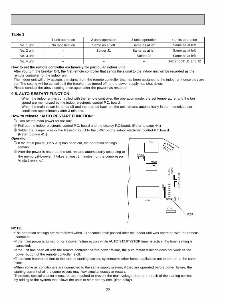
9-5. AUTO RESTART FUNCTIONWhen the indoor unit is controlled with the remote controller, the operation mode, the set temperature, and the fanspeed are memorized by the indoor electronic control P.C. board.When the main power is turned off and then turned back on, the unit restarts automatically in the memorized set conditions approximately after 3 minutes.
NOTE:•The operation settings are memorized when 10 seconds have passed after the indoor unit was operated with the remote
controller.•If the main power is turned off or a power failure occurs while AUTO START/STOP timer is active, the timer setting is
cancelled.•If the unit has been off with the remote controller before power failure, the auto restart function does not work as the
power button of the remote controller is off.•To prevent breaker off due to the rush of starting current, systematize other home appliances not to turn on at the same
time.•When some air conditioners are connected to the same supply system, if they are operated before power failure, the starting current of all the compressors may flow simultaneously at restart.Therefore, special counter-measures are required to prevent the main voltage-drop or the rush of the starting current by adding to the system that allows the units to start one by one. (time delay)
How to set the remote controller exclusively for particular indoor unitAfter you turn the breaker ON, the first remote controller that sends the signal to the indoor unit will be regarded as theremote controller for the indoor unit.The indoor unit will only accepts the signal from the remote controller that has been assigned to the indoor unit once they areset. The setting will be cancelled if the breaker has turned off, or the power supply has shut down.Please conduct the above setting once again after the power has restored.
Table 1
No. 1 unit
No. 2 unit
No. 3 unit
No. 4 unit
1 unit operation
No modification
–
–
–
2 units operation
Same as at left
Solder J1
–
–
3 units operation
Same as at left
Same as at left
Solder J2
–
4 units operation
Same as at left
Same as at left
Same as at left
Solder both J1 and J2
How to release “AUTO RESTART FUNCTION”1 Turn off the main power for the unit.2 Pull out the indoor electronic control P.C. board and the display P.C.board. (Refer to page 44.)3 Solder the Jumper wire or the Resistor 220Ω to the JR07 on the indoor electronic control P.C.board.
(Refer to page 41.)Operation1 If the main power (115V AC) has been cut, the operation settings
remain.2 After the power is restored, the unit restarts automatically according to
the memory.(However, it takes at least 3 minutes for the compressorto start running.)
JR07
IC152
CN
151
CN
112
CN
111
CN
121
SW
1
IC101
RA
102
C11
CN201
CN211
TAB12
OB310--1.qxp 04.1.13 9:47 AM Page 30
TROUBLESHOOTING10
31
3. Troubleshooting procedure1) First, check if the OPERATION INDICATOR lamp on the indoor unit is flashing on and off to indicate an abnormality.
To make sure, check how many times the abnormality indication is flashing on and off before starting service work.2) Before servicing check that the connector and terminal are connected properly.3) If the electronic control P.C. board is supposed to be defective, check the copper foil pattern for disconnection and the
components for bursting and discoloration.4) When troubleshooting, refer to the flow chart on page 32 and the check table on page 33.
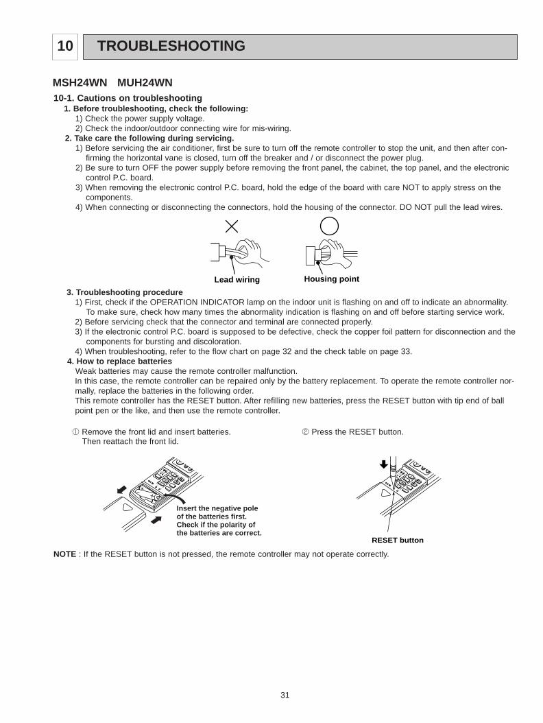
4. How to replace batteries Weak batteries may cause the remote controller malfunction.In this case, the remote controller can be repaired only by the battery replacement. To operate the remote controller nor-mally, replace the batteries in the following order.This remote controller has the RESET button. After refilling new batteries, press the RESET button with tip end of ballpoint pen or the like, and then use the remote controller.
Lead wiring Housing point
10-1. Cautions on troubleshooting1. Before troubleshooting, check the following:
1) Check the power supply voltage.2) Check the indoor/outdoor connecting wire for mis-wiring.
2. Take care the following during servicing.1) Before servicing the air conditioner, first be sure to turn off the remote controller to stop the unit, and then after con-
firming the horizontal vane is closed, turn off the breaker and / or disconnect the power plug.2) Be sure to turn OFF the power supply before removing the front panel, the cabinet, the top panel, and the electronic
control P.C. board.3) When removing the electronic control P.C. board, hold the edge of the board with care NOT to apply stress on the
components.4) When connecting or disconnecting the connectors, hold the housing of the connector. DO NOT pull the lead wires.
MSH24WN MUH24WN
1 Remove the front lid and insert batteries.Then reattach the front lid.
RESET button
Insert the negative pole of the batteries first.Check if the polarity of the batteries are correct.
NOTE : If the RESET button is not pressed, the remote controller may not operate correctly.
2 Press the RESET button.
OB310--2.qxp 04.1.13 9:49 AM Page 31
32
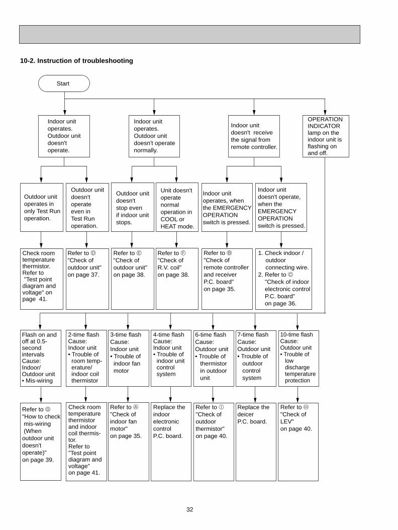
10-2. Instruction of troubleshooting
Start
Indoor unit operates.Outdoor unit doesn't operate.
Indoor unit doesn't receive the signal from remote controller.
Indoor unit operates.Outdoor unitdoesn't operatenormally.
OPERATIONINDICATORlamp on theindoor unit isflashing on and off.
Outdoor unit operates in only Test Run operation.
Outdoor unit doesn't operate even in Test Run operation.
Indoor unit operates, when the EMERGENCY OPERATION switch is pressed.
Indoor unit doesn't operate, when the EMERGENCY OPERATION switch is pressed.
Check room temperature thermistor.Refer to "Test point diagram and voltage" on page 41.
Refer to D "Check of outdoor unit" on page 37.
Refer to B "Check of remote controller and receiver P.C. board" on page 35.
Flash on and off at 0.5-second intervalsCause: Indoor/Outdoor unit• Mis-wiring
2-time flash Cause:Indoor unit• Trouble of room temp- erature/ indoor coil thermistor
3-time flash Cause:Indoor unit• Trouble of indoor fan motor
6-time flash Cause:Outdoor unit• Trouble of thermistor in outdoor unit
7-time flash Cause:Outdoor unit• Trouble of outdoor control system
Check room temperature thermistor and indoor coil thermis-tor.Refer to "Test point diagram and voltage" on page 41.
Refer to A "Check of indoor fan motor" on page 35.
Refer to I"Check of outdoor thermistor" on page 40.
Replace the deicer P.C. board.
10-time flash Cause:Outdoor unit• Trouble of low discharge temperature protection
Refer to H "Check of LEV"on page 40.
4-time flash Cause:Indoor unit• Trouble of indoor unit control system
Replace the indoor electronic control P.C. board.
1. Check indoor / outdoor connecting wire.2. Refer to C "Check of indoor electronic control P.C. board" on page 36.
Outdoor unit doesn't stop even if indoor unit stops.
Unit doesn't operate normaloperation in COOL or HEAT mode.
Refer to E "Check of outdoor unit" on page 38.
Refer to F "Check of R.V. coil" on page 38.
Refer to G"How to check mis-wiring (When outdoor unit doesn't operate)" on page 39.
OB310--2.qxp 04.1.13 9:49 AM Page 32
33
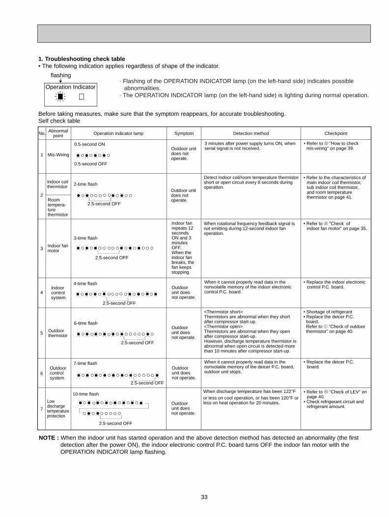
1. Troubleshooting check table• The following indication applies regardless of shape of the indicator.
Operation Indicator
flashing
Before taking measures, make sure that the symptom reappears, for accurate troubleshooting.Self check table
NOTE : When the indoor unit has started operation and the above detection method has detected an abnormality (the first detection after the power ON), the indoor electronic control P.C. board turns OFF the indoor fan motor with the OPERATION INDICATOR lamp flashing.
No.
1
2
4
5
6
SymptomOperation indicator lamp Detection method Checkpoint
0.5-second ON
0.5-second OFF
Mis-Wiring
Outdoor thermistor
Outdoor control system
Indoor coil thermistor
3 minutes after power supply turns ON, when serial signal is not received.
<Thermistor short>Thermistors are abnormal when they short after compressor start-up.<Thermistor open>Thermistors are abnormal when they open after compressor start-up.However, discharge temperature thermistor is abnormal when open circuit is detected more than 10 minutes after compressor start-up.
When it cannot properly read data in the nonvolatile memory of the deicer P.C. board, outdoor unit stops.
• Shortage of refrigerant• Replace the deicer P.C. board. Refer to I "Check of outdoor
thermistor" on page 40.
• Replace the deicer P.C. board.
• Refer to G "How to check mis-wiring" on page 39.
3Indoor fan motor
7
Low discharge temperature protection
When discharge temperature has been 122-F or less on cool operation, or has been 120-F or less on heat operation for 20 minutes.
Abnormal point
Outdoor unit does not operate.
Room tempera-ture thermistor
2-time flash
2.5-second OFF
Detect Indoor coil/room temperature thermistor short or open circuit every 8 seconds during operation.
• Refer to the characteristics of main indoor coil thermistor, sub indoor coil thermistor, and room temperature thermistor on page 41.
3-time flash
2.5-second OFF
Indoor fan repeats 12 seconds ON and 3 minutes OFF.When the indoor fan breaks, the fan keeps stopping.
When rotational frequency feedback signal is not emitting during 12-second indoor fan operation.
• Refer to A "Check of indoor fan motor" on page 35.
4-time flash
2.5-second OFF
Indoor control system
When it cannot properly read data in the nonvolatile memory of the indoor electronic control P.C. board.
Outdoor unit does not operate.
Outdoor unit does not operate.
• Replace the indoor electronic control P.C. board.
6-time flash
2.5-second OFF
• Refer to H "Check of LEV" on page 40.
• Check refrigerant circuit and refrigerant amount.
Outdoor unit does not operate.
Outdoor unit does not operate.
Outdoor unit does not operate.
7-time flash
2.5-second OFF
10-time flash
2.5-second OFF
· Flashing of the OPERATION INDICATOR lamp (on the left-hand side) indicates possible abnormalities.
· The OPERATION INDICATOR lamp (on the left-hand side) is lighting during normal operation.
OB310--2.qxp 04.1.13 9:49 AM Page 33
34
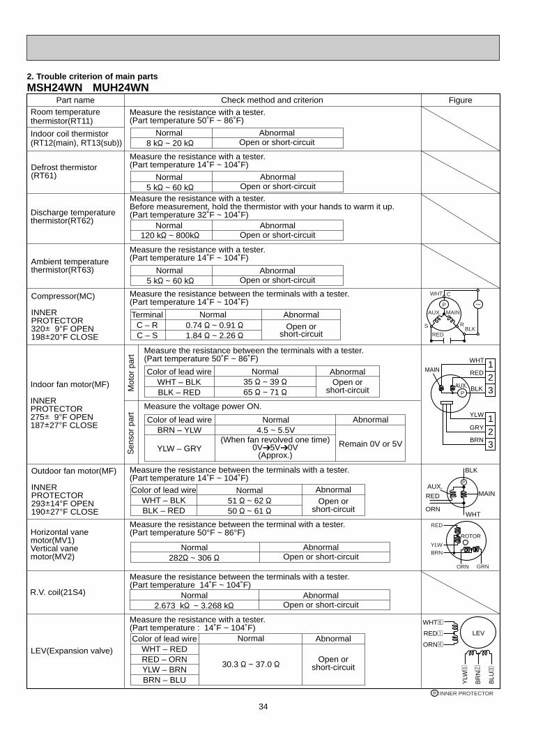
2. Trouble criterion of main partsMSH24WN MUH24WN
Part name FigureCheck method and criterion
Measure the resistance between the terminals with a tester.(Part temperature 14˚F ~ 104˚F)
Compressor(MC)
INNER PROTECTOR320i 9-F OPEN198i20-F CLOSE
Indoor fan motor(MF)
INNER PROTECTOR275i 9-F OPEN187i27-F CLOSE
NormalTerminalC – RC – S
0.74 " ~ 0.91 "1.84 " ~ 2.26 "
AbnormalOpen or
short-circuit
Measure the resistance with a tester.(Part temperature 14˚F ~ 104˚F)
Color of lead wireWHT – BLKBLK – RED
AbnormalOpen or
short-circuit
Normal35 " ~ 39 "65 " ~ 71 "
Measure the resistance with a tester.(Part temperature 50˚F ~ 86˚F)
Normal8 k" ~ 20 k"
AbnormalOpen or short-circuit
Room temperaturethermistor(RT11)
Indoor coil thermistor(RT12(main), RT13(sub))
Discharge temperaturethermistor(RT62)
Ambient temperature thermistor(RT63)
Outdoor fan motor(MF)
INNER PROTECTOR293i14-F OPEN190i27-F CLOSE
Horizontal vane motor(MV1)Vertical vane motor(MV2)
R.V. coil(21S4)
LEV(Expansion valve)
Measure the resistance with a tester. Before measurement, hold the thermistor with your hands to warm it up.(Part temperature 32˚F ~ 104˚F)
Normal120 k" ~ 800k"
AbnormalOpen or short-circuit
Normal5 k" ~ 60 k"
AbnormalOpen or short-circuit
Mot
or p
art
Sen
sor
part
Measure the resistance between the terminals with a tester.(Part temperature 50˚F ~ 86˚F)
Measure the voltage power ON.
Color of lead wireBRN – YLW
YLW – GRY
Abnormal
Remain 0V or 5V
Normal4.5 ~ 5.5V
(When fan revolved one time)0V5V0V
(Approx.)
Measure the resistance between the terminals with a tester.(Part temperature 14˚F ~ 104˚F)
Color of lead wireWHT – BLKBLK – RED
AbnormalOpen or
short-circuit
Normal51 " ~ 62 "50 " ~ 61 "
Normal282" ~ 306 "
AbnormalOpen or short-circuit
Measure the resistance between the terminal with a tester.(Part temperature 50°F ~ 86°F)
Measure the resistance between the terminals with a tester.(Part temperature 14˚F ~ 104˚F)
Normal2.673 k" ~ 3.268 k"
AbnormalOpen or short-circuit
Color of lead wireWHT – REDRED – ORNYLW – BRNBRN – BLU
Abnormal
Open orshort-circuit
Normal
30.3 " ~ 37.0 "
Measure the resistance with a tester.(Part temperature : 14˚F ~ 104˚F)
Measure the resistance with a tester.(Part temperature 14˚F ~ 104˚F)
Normal5 k" ~ 60 k"
AbnormalOpen or short-circuit
Defrost thermistor(RT61)
P
P
R
C
S
REDBLK
WHT
MAINAUX.
123
RED
BLK
MAIN
AUX.
YLW
GRY
BRN
WHT
123
RED
AUX.MAIN
ORN
BLK
WHT
P
RED
YLWBRN
ORN GRN
ROTOR
LEV
WHT6
RED1
ORN4
YLW
5
BR
N2
BLU
3
:INNER PROTECTORP
OB310--2.qxp 04.1.13 9:49 AM Page 34
35
Yes
Yes
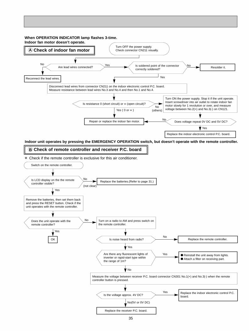
Check of indoor fan motorA
Check of remote controller and receiver P.C. boardB
When OPERATION INDICATOR lamp flashes 3-time.Indoor fan motor doesn’t operate.
Repair or replace the indoor fan motor.
Disconnect lead wires from connector CN211 on the indoor electronic control P.C. board.Measure resistance between lead wires No.3 and No.4 and then No.1 and No.4.
Are lead wires connected?
Reconnect the lead wires.
Is soldered point of the connectorcorrectly soldered?
Resolder it.
Is resistance 0 (short circuit) or ∞ (open circuit)?
Indoor unit operates by pressing the EMERGENCY OPERATION switch, but doesn’t operate with the remote controller.
Replace the batteries.(Refer to page 31.)
Turn on a radio to AM and press switch onthe remote controller.
Is noise heard from radio?
Are there any fluorescent lights ofinverter or rapid-start type withinthe range of 1m?
Measure the voltage between receiver P.C. board connector CN301 No.1(+) and No.3(-) when the remotecontroller button is pressed.
Is the voltage approx. 4V DC?Replace the indoor electronic control P.C.board.
Replace the receiver P.C. board.
Replace the remote controller.
Reinstall the unit away from lights. Attach a filter on receiving part.
Yes ( 0 or ∞ )No
(others)
Yes
NoYesNo
Switch on the remote controller.
Is LCD display on the the remotecontroller visible?
Remove the batteries, then set them backand press the RESET button. Check if theunit operates with the remote controller.
Yes
Does the unit operate with theremote controller?
Yes
OK
No
(not clear)
Yes
No
No
No(5V or 0V DC)
No
Turn OFF the power supply.Check connector CN211 visually.
w Check if the remote controller is exclusive for this air conditioner.
Turn ON the power supply. Stop it if the unit operate.Insert screwdriver into air outlet to rotate indoor fanmotor slowly for 1 revolution or over, and measurevoltage between No.2(+) and No.3(-) on CN121.
Replace the indoor electronic control P.C. board.
Does voltage repeat 0V DC and 5V DC?
Yes
No
OB310--2.qxp 04.1.13 9:49 AM Page 35
36
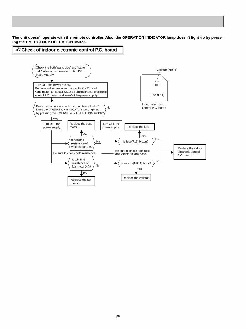
Check of indoor electronic control P.C. boardC
Check the both “parts side” and “pattern side” of indoor electronic control P.C. board visually.
Replace the fuse.
Is fuse(F11) blown?
Be sure to check both fuse and varistor in any case.
Replace the fan motor.
Replace the indoor electronic control P.C. board.
Is winding resistance of fan motor 0 "?
Is winding resistance of vane motor 0 "?
No
Yes
Replace the vane motor.
No
Yes
Yes
Is varistor(NR11) burnt?
Replace the varistor.
Yes
Turn OFF the power supply.Remove indoor fan motor connector CN211 and vane motor connector CN151 from the indoor electronic control P.C. board and turn ON the power supply.
No
No
Does the unit operate with the remote controller?Does the OPERATION INDICATOR lamp light up by pressing the EMERGENCY OPERATION switch?
Yes
No
Be sure to check both resistance.
Turn OFF the power supply.
Turn OFF the power supply.
Varistor (NR11)
Indoor electronic control P.C. board
Fuse (F11)
The unit doesn’t operate with the remote controller. Also, the OPERATION INDICATOR lamp doesn’t light up by press-ing the EMERGENCY OPERATION switch.
OB310--2.qxp 04.1.13 9:49 AM Page 36
37
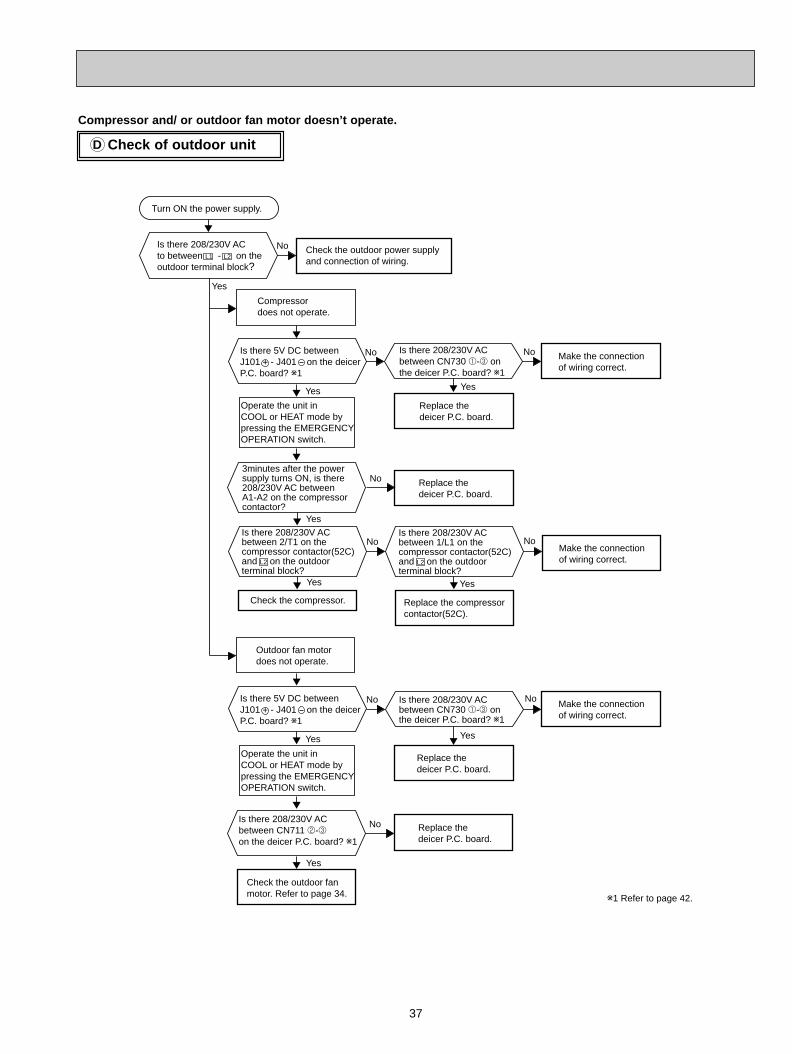
Check of outdoor unitD
Compressor and/ or outdoor fan motor doesn’t operate.
Is there 208/230V AC to between L1 - L2 on the outdoor terminal block?
No Check the outdoor power supply and connection of wiring.
Yes
Compressor does not operate.
Yes
3minutes after the power supply turns ON, is there 208/230V AC between A1-A2 on the compressorcontactor?
Operate the unit in COOL or HEAT mode by pressing the EMERGENCY OPERATION switch.
Outdoor fan motor does not operate.
No Make the connectionof wiring correct.
Check the compressor. Replace the compressor contactor(52C).
Turn ON the power supply.
Yes
Yes
Replace thedeicer P.C. board.
Replace the deicer P.C. board.
No
Yes
No
No
NoMake the connectionof wiring correct.
Yes
Yes Yes
Is there 208/230V AC between CN711 2-3 on the deicer P.C. board? w1
Operate the unit in COOL or HEAT mode by pressing the EMERGENCY OPERATION switch.
No Make the connectionof wiring correct.
Check the outdoor fan motor. Refer to page 34.
Yes
Is there 208/230V AC between CN730 1-3 on the deicer P.C. board? w1
Replace the deicer P.C. board.
Replace the deicer P.C. board.
No
No
Is there 5V DC between J101 - J401 on the deicer P.C. board? w1
Is there 208/230V AC between CN730 1-3 on the deicer P.C. board? w1
+
Is there 5V DC between J101 - J401 on the deicer P.C. board? w1
+
w1 Refer to page 42.
Is there 208/230V AC between 2/T1 on the compressor contactor(52C) and L2 on the outdoor terminal block?
Is there 208/230V AC between 1/L1 on the compressor contactor(52C) and L2 on the outdoor terminal block?
OB310--2.qxp 04.1.13 9:49 AM Page 37
38
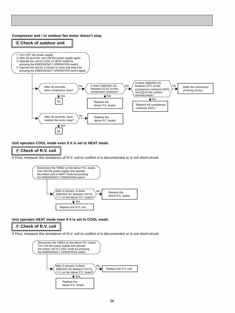
Check of outdoor unitE
Compressor and / or outdoor fan motor doesn’t stop.
Check of R.V. coilF
After 30 seconds, does compressor stop?
No
Yes
Is there 208/230V AC between A1-A2 on the compressor contactor?
Replace the deicer P.C. board.
Yes
1 Turn OFF the power supply.2 After 30 seconds, turn ON the power supply again.3 Operate the unit in COOL or HEAT mode by pressing the EMERGENCY OPERATION switch.4 Operate the unit for 1 minute or more and stop it by pressing the EMERGENCY OPERATION switch again.
Ok
No
After 30 seconds, does outdoor fan motor stop?
Replace thedeicer P.C. board.
Yes
Ok
No
Yes
Replace the compressor contactor (52C).
No Make the connectionof wiring correct.
Is there 208/230V AC between 2/T1 on the compressor contactor (52C) and L2 on the outdoor terminal block?
After 3 minutes, is there 208/230V AC between CN721 1-3 on the deicer P.C. board?
Replace the deicer P.C. board.
Yes
No
Replace the R.V. coil.
Disconnect the TAB52 on the deicer P.C. board.Turn ON the power supply and operate the indoor unit in HEAT mode by pressing the EMERGENCY OPERATION switch.
After 3 minutes, is there 208/230V AC between CN7211-3 on the deicer P.C. board?
Replace the deicer P.C. board.
Yes
NoReplace the R.V. coil.
Disconnect the TAB52 on the deicer P.C. board.Turn ON the power supply and operate the indoor unit in COOL mode by pressing the EMERGENCY OPERATION switch.
Unit operates COOL mode even if it is set to HEAT mode.
Unit operates HEAT mode even if it is set to COOL mode.
w First, measure the resistance of R.V. coil to confirm it is disconnected or is not short-circuit.
w First, measure the resistance of R.V. coil to confirm it is disconnected or is not short-circuit.
Check of R.V. coilF
OB310--2.qxp 04.1.13 9:49 AM Page 38
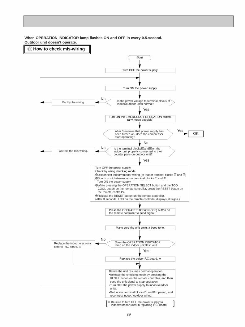
39
How to check mis-wiringG
Turn OFF the power supply.
Turn ON the power supply.
Turn ON the EMERGENCY OPERATION switch.(any mode possible)
Make sure the unit emits a beep tone.
Replace the deicer P.C.board.
Press the OPERATE/STOP(ON/OFF) button onthe remote controller to send signal.
Turn OFF the power supply.Check by using checking mode.11Disconnect indoor/outdoor wiring (at indoor terminal blocks 11 and 33)22Short circuit between indoor terminal blocks 11 and 33.
Turn ON the power supply.33While pressing the OPERATION SELECT button and the TOO
COOL button on the remote controller, press the RESET button onthe remote controller.
44Release the RESET button on the remote controller.(After 3 seconds, LCD on the remote controller displays all signs.)
Before the unit resumes normal operation.•Release the checking mode by pressing theRESET button on the remote controller, and thensend the unit signal to stop operation.
•Turn OFF the power supply to indoor/outdoor units.
•Get indoor terminal blocks 11 and 33 opened, andreconnect indoor/ outdoor wiring.
Is the power voltage to terminal blocks ofindoor/outdoor units normal?
Does the OPERATION INDICATORlamp on the indoor unit flash on?
Is the terminal blocks11and33 on theindoor unit properly connected to theircounter parts on outdoor unit?
Start
Correct the mis-wiring.
Be sure to turn OFF the power supply toindoor/outdoor units in replacing P.C. board.
Replace the indoor electroniccontrol P.C. board.
No
No
No
No
Yes
Yes
Yes
Yes
[ ]
OK
Rectify the wiring.
After 3 minutes that power supply hasbeen turned on, does the compressorstart operating?
When OPERATION INDICATOR lamp flashes ON and OFF in every 0.5-second.Outdoor unit doesn’t operate.
OB310--2.qxp 04.1.13 9:49 AM Page 39
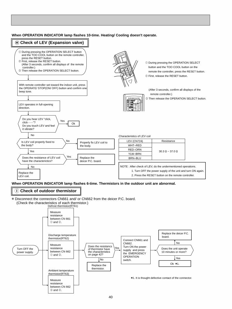
40
Check of outdoor thermistor
When OPERATION INDICATOR lamp flashes 6-time. Thermistors in the outdoor unit are abnormal.
I
Check of LEV (Expansion valve)H
Replace the LEV coil.
With remote controller set toward the indoor unit, press the OPERATE/ STOP(ON/ OFF) button and confirm one beep tone.
LEV operates in full-opening direction.
Is LEV coil properly fixed to the body?
Ok
Do you hear LEV "click, click·······"?Do you touch LEV and feel it vibrate?
Does the resistance of LEV coil have the characterictics?
No
Yes
Yes
Yes
No
LEV (CN724)
WHT–RED
RED–ORN
YLW–BRN
BRN–BLU
Resistance
30.3 " ~ 37.0 "
Characteristics of LEV coil
NoProperly fix LEV coil to the body.
Replace the deicer P.C. board.
NOTE : After check of LEV, do the undermentioned operations.
1. Turn OFF the power supply of the unit and turn ON again.
2. Press the RESET button on the remote controller.
1 During pressing the OPERATION SELECT button and the TOO COOL button on the remote controller, press the RESET button.
2 First, release the RESET button.(After 3 seconds, confirm all displays of the remote controller.)
3 Then release the OPERATION SELECT button.
1 During pressing the OPERATION SELECT
button and the TOO COOL button on the
remote the controller, press the RESET button.
2 First, release the RESET button.
(After 3 seconds, confirm all displays of the
remote controller.)
3 Then release the OPERATION SELECT button.
AMPMCLOCK
F
AMPM
When OPERATION INDICATOR lamp flashes 10-time. Heating/ Cooling doesn't operate.
w Disconnect the connectors CN661 and/ or CN662 from the deicer P.C. board.(Check the characteristics of each thermistor.)
Measure resistance between CN 661 1 and 2.
Measure resistance between CN 662 3 and 4.
No
Yes
Replace the thermistor.
Measure resistance between CN 662 1 and 2.
Connect CN661 and CN662.Turn ON the power supply and press the EMERGENCY OPERATION switch.
Does the resistancs of thermistor have the characteristics on page 42?
No
Yes
Does the unit operate 10 minutes or more?
Replace the deicer P.C. board.
Ok W1.
W1. It is thought defective contact of the connector.
Turn OFF the power supply.
Discharge temperature thermistor(RT62)
Ambient temperature thermistor(RT63)
Defrost thermistor(RT61)
OB310--2.qxp 04.1.13 9:49 AM Page 40
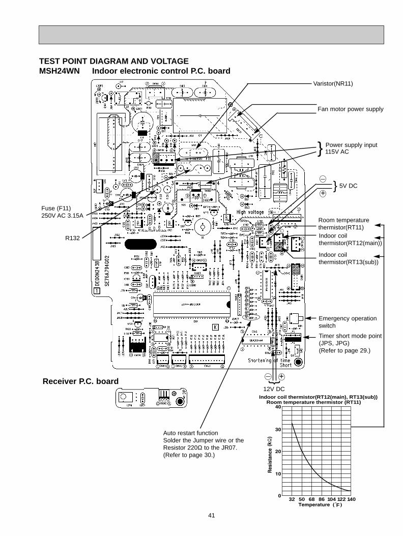
41
TEST POINT DIAGRAM AND VOLTAGEMSH24WN Indoor electronic control P.C. board
Fan motor power supply
Fuse (F11) 250V AC 3.15A
Power supply input115V AC
+ 5V DC
Indoor coil thermistor(RT12(main))
Timer short mode point(JPS, JPG)(Refer to page 29.)
Emergency operation switch
+
12V DCIndoor coil thermistor(RT12(main), RT13(sub))
Room temperature thermistor (RT11)
32F
50 68 86 104 122 140
Room temperaturethermistor(RT11)
Auto restart functionSolder the Jumper wire or theResistor 220Ω to the JR07. (Refer to page 30.)
Indoor coil thermistor(RT13(sub))
R132
Receiver P.C. board
Varistor(NR11)
OB310--2.qxp 04.1.13 9:50 AM Page 41
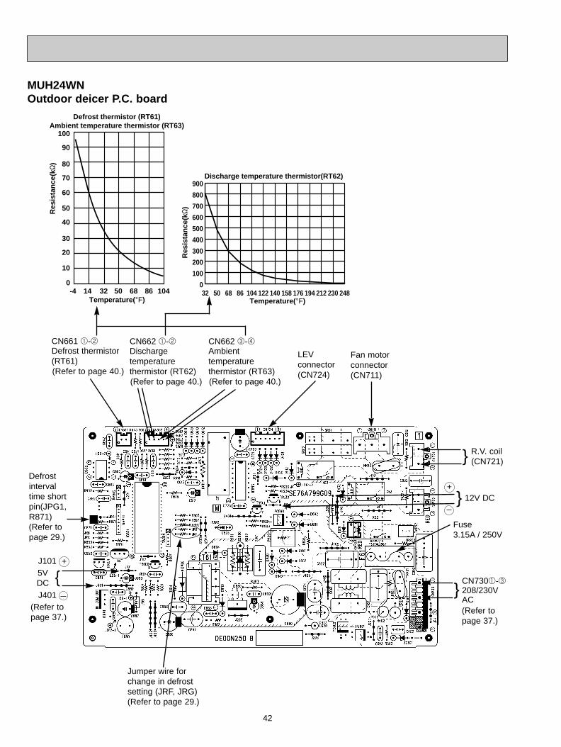
42
MUH24WN Outdoor deicer P.C. board
Fuse 3.15A / 250V
Defrostintervaltime shortpin(JPG1,R871)(Refer topage 29.)
12V DC
Jumper wire forchange in defrostsetting (JRF, JRG)(Refer to page 29.)
5V DC
+
+
CN661 1-2Defrost thermistor (RT61)(Refer to page 40.)
Temperature(-F)
Discharge temperature thermistor(RT62)R
esis
tan
ce(k"
)
32 50 68 86 104 122 140 158 176 194 212 230 2480
100
200
300
400
500
600
700
800
900
Defrost thermistor (RT61)Ambient temperature thermistor (RT63)
-4 14 32 50 68 86 1040
10
20
30
40
50
60
70
80
90
100
Temperature(-F)
Res
ista
nce
(k"
)
CN662 1-2Discharge temperature thermistor (RT62)(Refer to page 40.)
CN662 3-4Ambient temperature thermistor (RT63)(Refer to page 40.)
LEV connector(CN724)
Fan motorconnector(CN711)
CN7301-3208/230VAC
(Refer to page 37.)
(Refer to page 37.)
J101
J401
R.V. coil(CN721)
OB310--2.qxp 04.1.13 9:50 AM Page 42
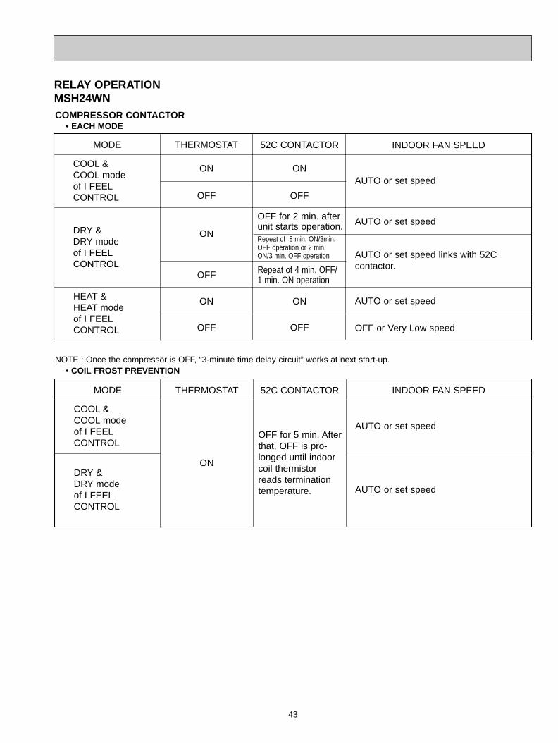
43
RELAY OPERATIONMSH24WN
MODE THERMOSTAT 52C CONTACTOR INDOOR FAN SPEED
COOL &COOL modeof I FEELCONTROL
DRY &DRY modeof I FEELCONTROL
HEAT &HEAT modeof I FEELCONTROL
ON
OFF
OFF
OFF
ON
ON ON
OFF
ON
OFF
OFF for 2 min. afterunit starts operation.Repeat of 8 min. ON/3min.OFF operation or 2 min. ON/3 min. OFF operation
Repeat of 4 min. OFF/1 min. ON operation
AUTO or set speed
AUTO or set speed
AUTO or set speed links with 52C contactor.
AUTO or set speed
OFF or Very Low speed
NOTE : Once the compressor is OFF, “3-minute time delay circuit” works at next start-up.• COIL FROST PREVENTION
MODE THERMOSTAT 52C CONTACTOR INDOOR FAN SPEED
COOL &COOL modeof I FEELCONTROL
DRY &DRY modeof I FEELCONTROL
ON
OFF for 5 min. Afterthat, OFF is pro-longed until indoorcoil thermistorreads terminationtemperature.
AUTO or set speed
AUTO or set speed
COMPRESSOR CONTACTOR • EACH MODE
OB310--2.qxp 04.1.13 9:50 AM Page 43
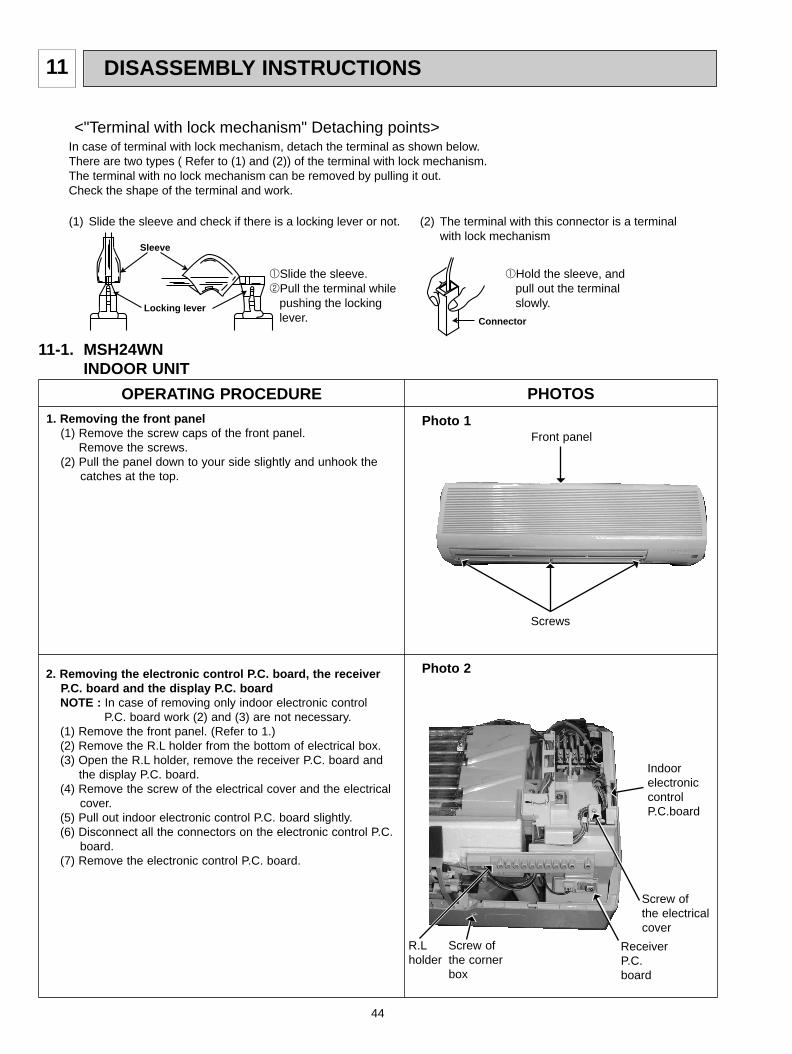
DISASSEMBLY INSTRUCTIONS11
44
11-1. MSH24WNINDOOR UNIT
(1) Slide the sleeve and check if there is a locking lever or not. (2) The terminal with this connector is a terminal with lock mechanism
1Slide the sleeve.2Pull the terminal while pushing the locking lever.
1Hold the sleeve, and pull out the terminal slowly.
In case of terminal with lock mechanism, detach the terminal as shown below.There are two types ( Refer to (1) and (2)) of the terminal with lock mechanism.The terminal with no lock mechanism can be removed by pulling it out.Check the shape of the terminal and work.
<"Terminal with lock mechanism" Detaching points>
Connector
Sleeve
Locking lever
OPERATING PROCEDURE PHOTOS1. Removing the front panel
(1) Remove the screw caps of the front panel.Remove the screws.
(2) Pull the panel down to your side slightly and unhook thecatches at the top.
Photo 1
Photo 2
Front panel
Screws
Screw of the electricalcover
R.Lholder
ReceiverP.C.board
2. Removing the electronic control P.C. board, the receiverP.C. board and the display P.C. boardNOTE : In case of removing only indoor electronic control
P.C. board work (2) and (3) are not necessary.(1) Remove the front panel. (Refer to 1.)(2) Remove the R.L holder from the bottom of electrical box.(3) Open the R.L holder, remove the receiver P.C. board and
the display P.C. board.(4) Remove the screw of the electrical cover and the electrical
cover.(5) Pull out indoor electronic control P.C. board slightly.(6) Disconnect all the connectors on the electronic control P.C.
board.(7) Remove the electronic control P.C. board.
IndoorelectroniccontrolP.C.board
Screw ofthe cornerbox
OB310--2.qxp 04.1.13 9:50 AM Page 44
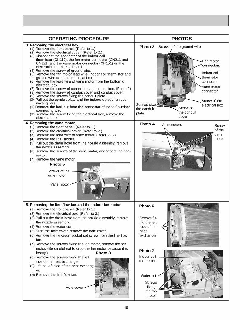
3. Removing the electrical box(1) Remove the front panel. (Refer to 1.)(2) Remove the electrical cover. (Refer to 2.)(3) Disconnect the connector of the indoor coil
thermistor (CN112), the fan motor connector (CN211 andCN121) and the vane motor connector (CN151) on theelectronic control P.C. board.
(4) Remove the screw of ground wire.(5) Remove the fan motor lead wire, indoor coil thermistor and
ground wire from the electrical box.(6) Remove the lead wire of vane motor from the bottom of
electrical box.(7) Remove the screw of corner box and corner box. (Photo 2)(8) Remove the screw of conduit cover and conduit cover.(9) Remove the screws fixing the conduit plate.(10) Pull out the conduit plate and the indoor/ outdoor unit con-
necting wire.(11) Remove the lock nut from the connector of indoor/ outdoor
connecting wire.(12) Remove the screw fixing the electrical box, remove the
electrical box.4. Removing the vane motor
(1) Remove the front panel. (Refer to 1.)(2) Remove the electrical cover. (Refer to 2.)(3) Remove the lead wire of vane motor. (Refer to 3.)(4) Remove the R.L. holder.(5) Pull out the drain hose from the nozzle assembly, remove
the nozzle assembly.(6) Remove the screws of the vane motor, disconnect the con-
nector.(7) Remove the vane motor.
5. Removing the line flow fan and the indoor fan motor(1) Remove the front panel. (Refer to 1.)(2) Remove the electrical box. (Refer to 3.)(3) Pull out the drain hose from the nozzle assembly, remove
the nozzle assembly.(4) Remove the water cut.(5) Slide the hole cover, remove the hole cover.(6) Remove the hexagon socket set screw from the line flow
fan.(7) Remove the screws fixing the fan motor, remove the fan
motor. (Be careful not to drop the fan motor because it isheavy.)
(8) Remove the screws fixing the leftside of the heat exchanger.
(9) Lift the left side of the heat exchang-er.
(10) Remove the line flow fan.
45
OPERATING PROCEDURE PHOTOS
Photo 4
Photo 6
Vane motors
Indoor coilthermistor
Photo 3
Screwsfixing
the fanmotor
Screws fix-ing the leftside of theheatexchanger
Screwsof thevanemotor
Screws of thevane motor
Screw of theelectrical box
Screws of the ground wire
Photo 5
Photo 7Photo 8
Hole cover
Water cut
Screw ofthe conduitcover
Vane motor
Vane motor connector
Fan motorconnectors
Indoor coilthermistorconnector
Screws ofthe conduitplate
OB310--2.qxp 04.1.13 9:50 AM Page 45
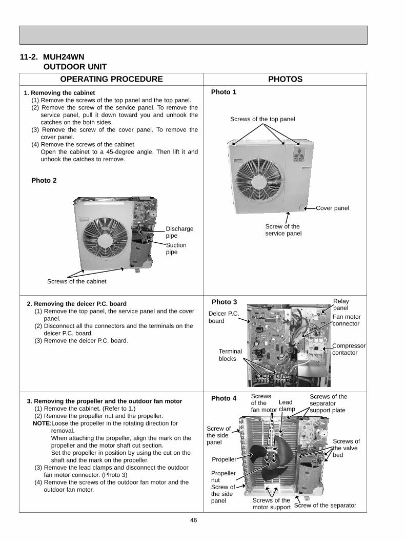
46
11-2. MUH24WNOUTDOOR UNIT
OPERATING PROCEDURE PHOTOS
Photo 1
Photo 2
Photo 4
Propellernut
Screws ofthe valvebed
Screws of the separator support plate
Screws of the motor support
Propeller
Screws of the cabinet
Cover panel
Screws of the top panel
Photo 3
Terminal blocks
Compressorcontactor
1. Removing the cabinet(1) Remove the screws of the top panel and the top panel.(2) Remove the screw of the service panel. To remove the
service panel, pull it down toward you and unhook thecatches on the both sides.
(3) Remove the screw of the cover panel. To remove thecover panel.
(4) Remove the screws of the cabinet. Open the cabinet to a 45-degree angle. Then lift it andunhook the catches to remove.
3. Removing the propeller and the outdoor fan motor(1) Remove the cabinet. (Refer to 1.)(2) Remove the propeller nut and the propeller.
NOTE:Loose the propeller in the rotating direction for removal.When attaching the propeller, align the mark on thepropeller and the motor shaft cut section.Set the propeller in position by using the cut on theshaft and the mark on the propeller.
(3) Remove the lead clamps and disconnect the outdoor fan motor connector. (Photo 3)
(4) Remove the screws of the outdoor fan motor and the outdoor fan motor.
2. Removing the deicer P.C. board(1) Remove the top panel, the service panel and the cover
panel.(2) Disconnect all the connectors and the terminals on the
deicer P.C. board.(3) Remove the deicer P.C. board.
Deicer P.C.board
Screw of the service panel
Discharge pipe
Screw ofthe sidepanel
Screw ofthe sidepanel
Screw of the separator
Fan motorconnector
Screws of thefan motor
Lead clamp
Relay panel
Suctionpipe
OB310--2.qxp 04.1.13 9:50 AM Page 46
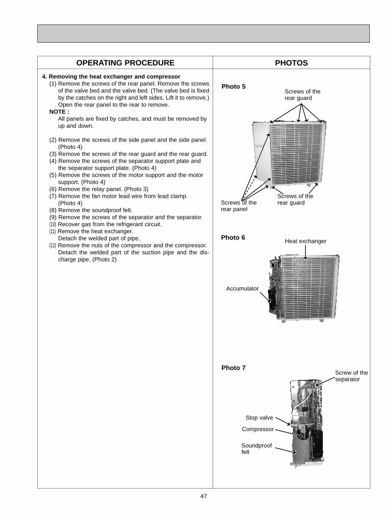
47
OPERATING PROCEDURE PHOTOS
Photo 5
Photo 6
Photo 7
Stop valve
Heat exchanger
Accumulator
Screws of the rear guard
4. Removing the heat exchanger and compressor(1) Remove the screws of the rear panel. Remove the screws
of the valve bed and the valve bed. (The valve bed is fixedby the catches on the right and left sides. Lift it to remove.)Open the rear panel to the rear to remove.
NOTE :All panels are fixed by catches, and must be removed by up and down.
(2) Remove the screws of the side panel and the side panel.(Photo 4)
(3) Remove the screws of the rear guard and the rear guard.(4) Remove the screws of the separator support plate and
the separator support plate. (Photo 4)(5) Remove the screws of the motor support and the motor
support. (Photo 4)(6) Remove the relay panel. (Photo 3)(7) Remove the fan motor lead wire from lead clamp.
(Photo 4)(8) Remove the soundproof felt.(9) Remove the screws of the separator and the separator.(10) Recover gas from the refrigerant circuit.(11) Remove the heat exchanger.
Detach the welded part of pipe.(12) Remove the nuts of the compressor and the compressor.
Detach the welded part of the suction pipe and the dis-charge pipe. (Photo 2)
Compressor
Soundprooffelt
Screw of theseparator
Screws of the rear guardScrews of the
rear panel
OB310--2.qxp 04.1.13 9:50 AM Page 47
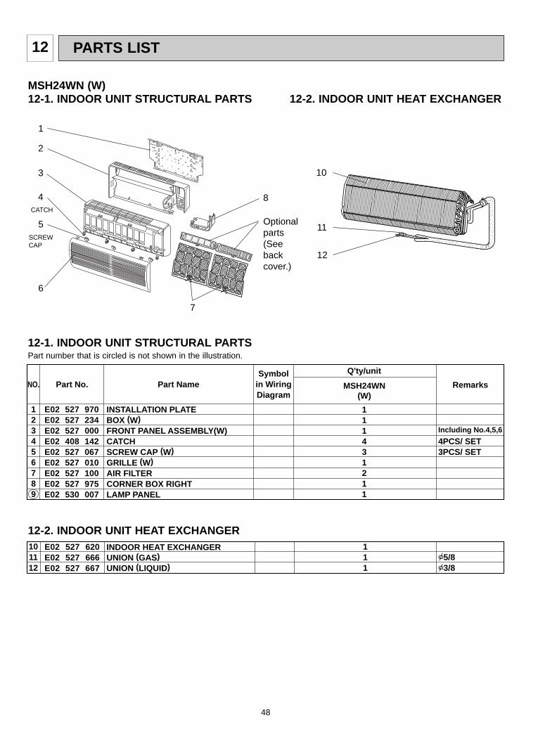
PARTS LIST12
48
MSH24WN (W)12-1. INDOOR UNIT STRUCTURAL PARTS
MSH24WN
E02 527 970E02 527 234E02 527 000E02 408 142E02 527 067E02 527 010E02 527 100E02 527 975E02 530 007
INSTALLATION PLATEBOX (W)FRONT PANEL ASSEMBLY(W)CATCHSCREW CAP (W)GRILLE (W)AIR FILTERCORNER BOX RIGHT LAMP PANEL
Symbolin WiringDiagram
Q'ty/unit
Including No.4,5,6
4PCS/ SET3PCS/ SET
RemarksPart No.NO. Part Name
123456789
111431211
(W)
12-2. INDOOR UNIT HEAT EXCHANGER
2
4
5
7
6
1
10
8
11
12
3
CATCH
SCREWCAP
E02 527 620E02 527 666E02 527 667
INDOOR HEAT EXCHANGERUNION (GAS)UNION (LIQUID)
5/83/8
101112
111
12-2. INDOOR UNIT HEAT EXCHANGER
12-1. INDOOR UNIT STRUCTURAL PARTS
Optionalparts(Seebackcover.)
Part number that is circled is not shown in the illustration.
OB310--2.qxp 04.1.13 9:50 AM Page 48
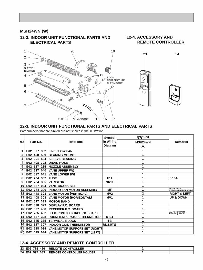
49
MSH24WN
E02 527 302E02 408 509E02 001 504E02 408 702E02 527 235E02 527 040E02 527 041E02 784 382E02 784 385E02 527 034E02 784 300E02 448 303E02 408 303E02 527 333E02 528 329E02 527 468E02 785 452E02 527 308E02 545 375E02 527 307E02 528 034E02 529 034
12345678910111213141516171819202122
LINE FLOW FANBEARING MOUNTSLEEVE BEARINGDRAIN HOSENOZZLE ASSEMBLYVANE UPPER (W)VANE LOWER (W)FUSEVARISTORVANE CRANK SETINDOOR FAN MOTOR ASSEMBLYVANE MOTOR (VERTICAL)VANE MOTOR (HORIZONTAL)MOTOR BANDDISPLAY P.C. BOARDRECEIVER P.C. BOARDELECTRONIC CONTROL P.C. BOARDROOM TEMPERATURE THERMISTORTERMINAL BLOCKINDOOR COIL THERMISTORVANE MOTOR SUPPORT SET (RIGHT)VANE MOTOR SUPPORT SET (LEFT)
Symbolin WiringDiagram
Q'ty/unit
3.15A
RIGHT & LEFTUP & DOWN
RemarksPart No.NO. Part Name
F11NR11
MFMV2MV1
RT11TB
RT12, RT13
1111111111121 111111111
(W)
RC4W33 -Including RUBBER MOUNT
AUTO RESTART Including No.16
Part numbers that are circled are not shown in the illustration.
MSH24WN (W)12-4. ACCESSORY AND
REMOTE CONTROLLER12-3. INDOOR UNIT FUNCTIONAL PARTS AND
ELECTRICAL PARTS
23 24
12-3. INDOOR UNIT FUNCTIONAL PARTS AND ELECTRICAL PARTS
19
2
6
4
7
13
5
3
12
1
18
20
10
179
SLEEVE BEARING
ROOM TEMPERATURE THERMISTOR
VARISTORFUSE
2324
E02 785 426E02 527 083
REMOTE CONTROLLERREMOTE CONTROLLER HOLDER
11
12-4. ACCESSORY AND REMOTE CONTROLLER
8 15 16
11
14
OB310--2.qxp 04.1.13 9:50 AM Page 49
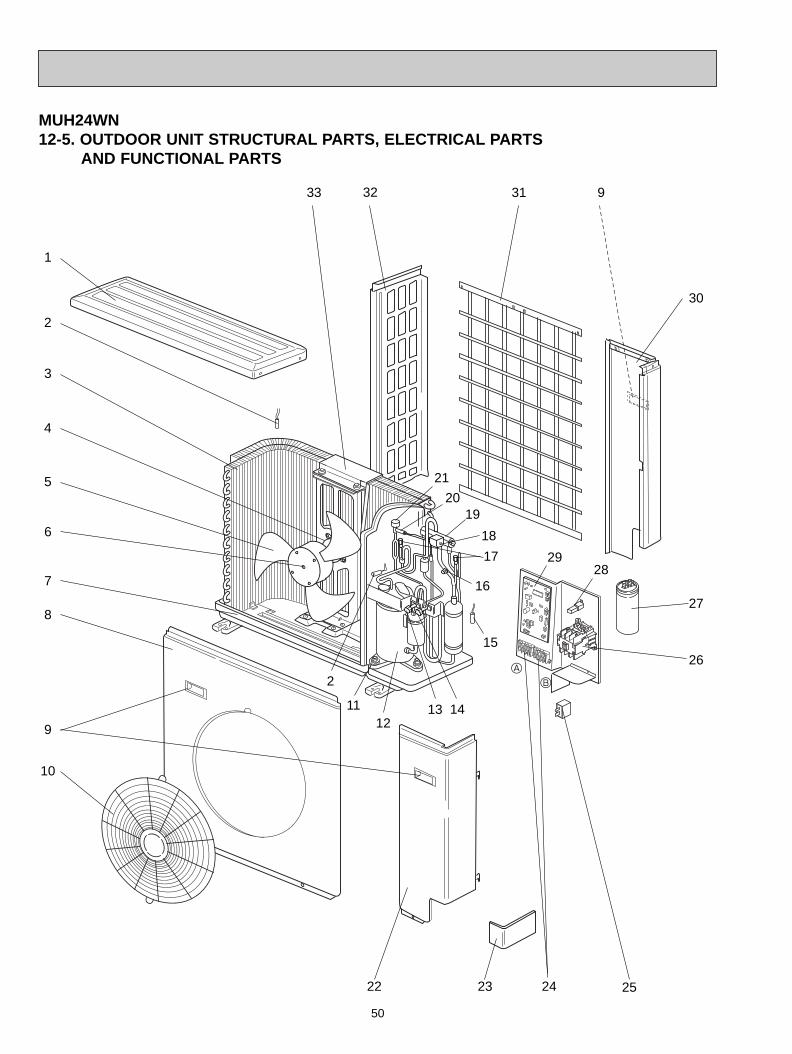
MUH24WN12-5. OUTDOOR UNIT STRUCTURAL PARTS, ELECTRICAL PARTS
AND FUNCTIONAL PARTS
1
3
5
32
2
30
28
10
167
27
6
33
8
4
2
11
24
12
18
19
26
31
9
25
1413
2322
B
A
9
21
20
50
17
15
29
OB310--2.qxp 04.1.13 9:50 AM Page 50
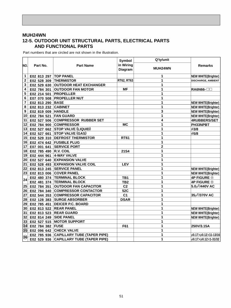
51
MUH24WN12-5. OUTDOOR UNIT STRUCTURAL PARTS, ELECTRICAL PARTS
AND FUNCTIONAL PARTS
MUH24WN
Symbolin WiringDiagram
Q'ty/unit
RemarksPart No.NO. Part Name
E02 813 297E02 528 309E02 529 630E02 784 301 E02 214 501E07 070 508E02 813 290E02 813 232E02 819 009E02 784 521E02 527 506E02 784 900E02 527 662E02 527 661E02 529 310E02 474 642E07 001 641E02 785 490E02 444 961E02 527 640E02 528 493E02 813 245E02 813 006E02 480 374E02 481 374E02 784 351E02 784 340E02 544 353E02 128 383E02 785 451E02 813 522E02 813 523E02 814 249E02 527 515 E02 784 382E02 096 642E02 785 936E02 529 936
1234567891011121314151617181920212223
24
2526272829303132333435
36
TOP PANELTHERMISTOROUTDOOR HEAT EXCHANGEROUTDOOR FAN MOTORPROPELLERPROPELLER NUTBASECABINETHANDLEFAN GUARDCOMPRESSOR RUBBER SETCOMPRESSOR STOP VALVE (LIQUID)STOP VALVE (GAS)DEFROST THERMISTORFUSIBLE PLUGSERVICE PORTR.V. COIL4-WAY VALVEEXPANSION VALVEEXPANSION VALVE COILSERVICE PANELCOVER PANELTERMINAL BLOCKTERMINAL BLOCKOUTDOOR FAN CAPACITORCOMPRESSOR CONTACTORCOMPRESSOR CAPACITORSURGE ABSORBERDEICER P.C. BOARDREAR PANELREAR GUARDSIDE PANELMOTOR SUPPORTFUSECHECK VALVECAPILLARY TUBE (TAPER PIPE)CAPILLARY TUBE (TAPER PIPE)
NEW WHITE(Brighter)DISCHARGE, AMBIENT
RA6N66-
NEW WHITE(Brighter)NEW WHITE(Brighter)NEW WHITE(Brighter)NEW WHITE(Brighter)4RUBBERS/SETPH33NPBT3/85/8
NEW WHITE(Brighter)NEW WHITE(Brighter)4P FIGURE A4P FIGURE B5.0+/440V AC
35+/370V AC
NEW WHITE(Brighter)NEW WHITE(Brighter)NEW WHITE(Brighter)
250V/3.15A
0.170.1211-13/160.170.121-31/32
RT62, RT63
MF
MC
RT61
21S4
LEV
TB1TB2C2
52CC1
DSAR
F61
11111111314111112111111111111111111111
Part numbers that are circled are not shown in the illustration.
OB310--2.qxp 04.1.13 9:50 AM Page 51
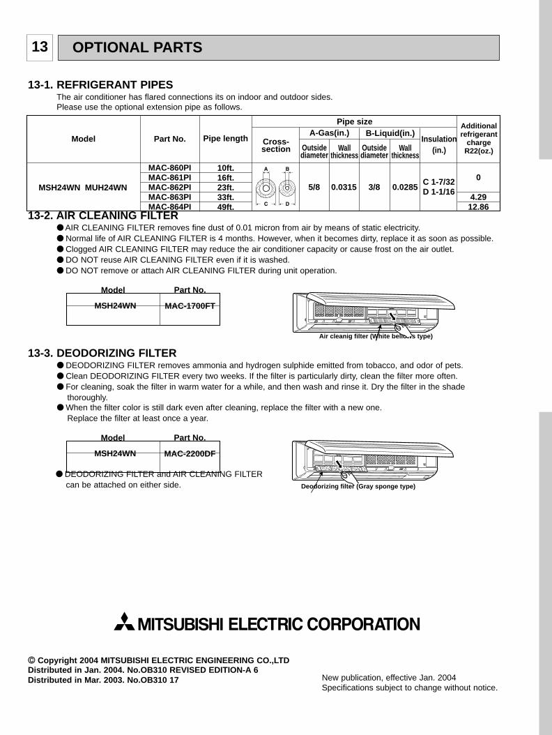
OPTIONAL PARTS13
New publication, effective Jan. 2004Specifications subject to change without notice.
CC Copyright 2004 MITSUBISHI ELECTRIC ENGINEERING CO.,LTDDistributed in Jan. 2004. No.OB310 REVISED EDITION-A 6Distributed in Mar. 2003. No.OB310 17
13-2. AIR CLEANING FILTER AIR CLEANING FILTER removes fine dust of 0.01 micron from air by means of static electricity. Normal life of AIR CLEANING FILTER is 4 months. However, when it becomes dirty, replace it as soon as possible. Clogged AIR CLEANING FILTER may reduce the air conditioner capacity or cause frost on the air outlet. DO NOT reuse AIR CLEANING FILTER even if it is washed. DO NOT remove or attach AIR CLEANING FILTER during unit operation.
13-3. DEODORIZING FILTER DEODORIZING FILTER removes ammonia and hydrogen sulphide emitted from tobacco, and odor of pets. Clean DEODORIZING FILTER every two weeks. If the filter is particularly dirty, clean the filter more often. For cleaning, soak the filter in warm water for a while, and then wash and rinse it. Dry the filter in the shade
thoroughly. When the filter color is still dark even after cleaning, replace the filter with a new one.
Replace the filter at least once a year.
DEODORIZING FILTER and AIR CLEANING FILTERcan be attached on either side.
Pipe length Cross-section
Part No.ModelA-Gas(in.) B-Liquid(in.)
Pipe size
Insulation(in.)
Additionalrefrigerant
chargeR22(oz.)Outside
diameterWall
thicknessOutside diameter
Wall thickness
MSH24WN MUH24WN
10ft.16ft.23ft.33ft.49ft.
0
4.2912.86
5/8 0.0315 3/8C 1-7/32D 1-1/160.0285
MAC-860PIMAC-861PIMAC-862PIMAC-863PIMAC-864PI
13-1. REFRIGERANT PIPESThe air conditioner has flared connections its on indoor and outdoor sides.Please use the optional extension pipe as follows.
Model Part No.
MAC-1700FTMSH24WN
Model Part No.
MAC-2200DFMSH24WN
Deodorizing filter (Gray sponge type)
Air cleanig filter (White bellows type)
OB310--2.qxp 04.1.13 9:50 AM Page 52

3400 Lawrenceville Suwanee Road Suwanee, Georgia 30024 Toll Free: 800-433-4822 Toll Free Fax: 800-889-9904
www.mrslim.com
Specifications are subject to change without notice.