Model:PURY-P240TSLMU-A (-BS) (Consists of Two PURY...
5
Specifications are subject to change without notice. © 2016 Mitsubishi Electric US, Inc. Model:PURY-P240TSLMU-A (-BS) (Consists of Two PURY-P120TLMU-A and One CMY-ER200CBK Twinning Kit) Job Name: System Reference: Date: OUTDOOR VRF HEAT PUMP WITH HEAT RECOVERY SYSTEM UNIT OPTION Standard Model ................................................................. PURY-P240TSLMU-A Seacost (BS) model .................................................... PURY-P240TSLMU-A-BS ACCESSORIES Twinning Kit (required) .............................................................. CMY-ER200CBK Joint Kit ............................................ For details see Pipe Accessories Submittal BC Controller (Required) ................. For details see Pipe Accessories Submittal Low Ambient Kit .................................. for details see Low Ambient Kit Submittal Snow/Hail Guards Kit ..................For detials see Snow/Hail Guards kit submittal Base Pan Heater Kit ................... For details see Base Pan Heater Kit Submittal Specifications System Unit Type PURY-P240TSLMU-A-(-BS) Nominal Cooling Capacity (208/230V) Btu/h 240,000 Nominal Heating Capacity (208/230V) Btu/h 270,000 Operating Temperature Range *1 Cooling (Indoor)*1 Refer to Module Data Heating (Indoor) External Dimensions (H x W x D) In. (mm) Refer to Module Data Net Weight Lbs. (kg) 1390 (630) External Finish Refer to Module Data Electrical Power Requirements Voltage, Phase, Hertz Refer to Module Data** Minimum Circuit Ampacity (MCA)** A Refer to Module Data** Maximum Overcurrent Protection (MOP)** A Refer to Module Data** Piping Diameter (Brazed) From Twinning Kit to First Joint or Header (In. / mm) Liquid (High Pressure) 1-1/8 / 28.58 Gas (Low Pressure) 1-3/8 / 34.9 From Modules to Twinning Kit (In. / mm) Liquid (High Pressure) Refer to Module Data Gas (Low Pressure) Refer to Module Data Max. Total Refrigerant Line Length Ft. 2,460 Max. Refrigerant Line Length (Bet.ODU & IDU) Ft. 541 Max. Control Wiring Length Ft. 1,640 Indoor Unit Total Capacity 50~150 Model / Quantity P6~P96 / 2~50 Sound Pressure Level dB(A) 63 Fan Type x Quantity Refer to Module Data Airflow Rate CFM External Static Pressure In. WG Compressor Operating Range 7% - 100% Compressor Type x Quantity Refer to Module Data Refrigerant Refer to Module Data Protection Devices High Pressure Refer to Module Data Inverter Circuit (Comp. / Fan) AHRI Ratings (Ducted/Non-Ducted) EER 11.8 / 12.9 IEER 19 / 22.3 COP 3.45 / 3.64 SCHE 22.9 / 26.8 Module 1 Module 2 PURY-P120TLMU-A-(-BS) PURY-P120TLMU-A-(-BS) 120,000 120,000 135,000 135,000 23 ~ 126 °F(-5 ~ 52 °C) DB 23 ~ 126 °F(-5 ~ 52 °C) DB -4 ~ +60° F ( -20 ~ +15.5° C) WB -4 ~ +60° F ( -20 ~ +15.5° C) WB 64-31/32 x 68-29/32 x 29-5/32 (1650 x 1750 x 740) 64-31/32 x 68-29/32 x 29-5/32 (1650 x 1750 x 740) 695 (315) 695 (315) Pre-coated galvanized steel sheet (+powder coating for -BS type) 208 / 230V, 3-phase, 60Hz 42 / 39 42 / 39 60 60 Refer to System Data Refer to System Data Refer to System Data Refer to System Data 3/4 / 19.05 3/4 / 19.05 1-1/8 / 28.6 1-1/8 / 28.6 Refer to System Data Refer to System Data Refer to System Data Refer to System Data Refer to System Data Refer to System Data Refer to System Data Refer to System Data Propeller fan x 2 Propeller fan x 2 11,300 11,300 Selectable; 0, 0.12 or 0.24”WG; factory set to 0”W.G. Refer to System Data Refer to System Data Inverter scroll hermetic compressor x 1 Inverter scroll hermetic compressor x 1 R410A x 23 lbs. + 2 oz. (10.5 kg) R410A x 23 lbs. + 2 oz. (10.5 kg) High pressure sensor, High pressure switch at 4.15 MPa (601 psi) High pressure sensor, High pressure switch at 4.15 MPa (601 psi) Over-heat protection, Over-current protection Over-heat protection, Over-current protection Refer to System Data Refer to System Data Refer to System Data Refer to System Data NOTES: *1. Harsh weather environments may demand performance enhancing equipment. Ask your Mitsubishi Electric representative for more details about your region. *2. For details on extended cooling operation range down to -10° F DB, see Low Ambient Kit Submittal. ** Each individual module requires a separate electrical connection. Reference electrical data for each individual module.
-
Upload
trinhduong -
Category
Documents
-
view
218 -
download
0
Transcript of Model:PURY-P240TSLMU-A (-BS) (Consists of Two PURY...

Specifications are subject to change without notice. © 2016 Mitsubishi Electric US, Inc.
Model:PURY-P240TSLMU-A (-BS) (Consists of Two PURY-P120TLMU-A and One CMY-ER200CBK Twinning Kit)
Job Name: System Reference: Date:
OUTDOOR VRF HEAT PUMP WITH HEAT RECOVERY SYSTEM
UNIT OPTION Standard Model ................................................................. PURY-P240TSLMU-A Seacost (BS) model .................................................... PURY-P240TSLMU-A-BS
ACCESSORIES Twinning Kit (required) ..............................................................CMY-ER200CBK Joint Kit ............................................ For details see Pipe Accessories Submittal BC Controller (Required) ................. For details see Pipe Accessories Submittal Low Ambient Kit .................................. for details see Low Ambient Kit Submittal Snow/Hail Guards Kit ..................For detials see Snow/Hail Guards kit submittal Base Pan Heater Kit ...................For details see Base Pan Heater Kit Submittal
Specifications SystemUnit Type PURY-P240TSLMU-A-(-BS)
Nominal Cooling Capacity (208/230V) Btu/h 240,000Nominal Heating Capacity(208/230V) Btu/h 270,000
Operating Temperature Range *1
Cooling (Indoor)*1 Refer to Module DataHeating (Indoor)
External Dimensions (H x W x D) In. (mm) Refer to Module Data
Net Weight Lbs. (kg) 1390 (630)External Finish Refer to Module Data
Electrical Power Requirements Voltage, Phase, Hertz Refer to Module Data**
Minimum Circuit Ampacity (MCA)** A Refer to Module Data**
Maximum Overcurrent Protection (MOP)** A Refer to Module Data**
Piping Diameter (Brazed)From Twinning Kit to First Joint or Header (In. / mm)
Liquid (High Pressure) 1-1/8 / 28.58Gas (Low Pressure) 1-3/8 / 34.9
From Modules to Twinning Kit (In. / mm)
Liquid (High Pressure) Refer to Module DataGas (Low Pressure) Refer to Module Data
Max. Total Refrigerant Line Length Ft. 2,460Max. Refrigerant Line Length (Bet.ODU & IDU) Ft. 541
Max. Control Wiring Length Ft. 1,640
Indoor UnitTotal Capacity 50~150Model / Quantity P6~P96 / 2~50
Sound Pressure Level dB(A) 63FanType x Quantity
Refer to Module DataAirflow Rate CFMExternal Static Pressure In. WGCompressor Operating Range 7% - 100%Compressor Type x Quantity Refer to Module DataRefrigerant Refer to Module Data
Protection DevicesHigh Pressure
Refer to Module DataInverter Circuit(Comp. / Fan)
AHRI Ratings(Ducted/Non-Ducted)
EER 11.8 / 12.9IEER 19 / 22.3COP 3.45 / 3.64SCHE 22.9 / 26.8
Module 1 Module 2PURY-P120TLMU-A-(-BS) PURY-P120TLMU-A-(-BS)
120,000 120,000
135,000 135,000
23 ~ 126 °F(-5 ~ 52 °C) DB 23 ~ 126 °F(-5 ~ 52 °C) DB-4 ~ +60° F ( -20 ~ +15.5° C) WB -4 ~ +60° F ( -20 ~ +15.5° C) WB
64-31/32 x 68-29/32 x 29-5/32 (1650 x 1750 x 740)
64-31/32 x 68-29/32 x 29-5/32 (1650 x 1750 x 740)
695 (315) 695 (315)Pre-coated galvanized steel sheet (+powder coating for -BS type)
208 / 230V, 3-phase, 60Hz
42 / 39 42 / 39
60 60
Refer to System Data Refer to System DataRefer to System Data Refer to System Data
3/4 / 19.05 3/4 / 19.051-1/8 / 28.6 1-1/8 / 28.6
Refer to System Data Refer to System Data
Refer to System Data Refer to System DataRefer to System Data Refer to System DataRefer to System Data Refer to System Data
Propeller fan x 2 Propeller fan x 211,300 11,300
Selectable; 0, 0.12 or 0.24”WG; factory set to 0”W.G.Refer to System Data Refer to System Data
Inverter scroll hermetic compressor x 1 Inverter scroll hermetic compressor x 1R410A x 23 lbs. + 2 oz. (10.5 kg) R410A x 23 lbs. + 2 oz. (10.5 kg)
High pressure sensor, High pressure switch at 4.15 MPa (601 psi)
High pressure sensor, High pressure switch at 4.15 MPa (601 psi)
Over-heat protection, Over-current protection
Over-heat protection, Over-current protection
Refer to System DataRefer to System DataRefer to System DataRefer to System Data
NOTES:*1. Harsh weather environments may demand performance enhancing equipment. Ask your Mitsubishi Electric representative for more details about your region.*2. For details on extended cooling operation range down to -10° F DB, see Low Ambient Kit Submittal.** Each individual module requires a separate electrical connection. Reference electrical data for each individual module.
Specifications are subject to change without notice. © 2016 Mitsubishi Electric US, Inc.
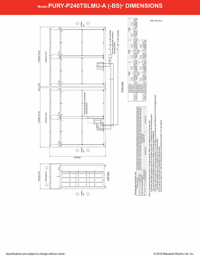
Model:PURY-P240TSLMU-A (-BS)- DIMENSIONS
bTo
BC
con
trolle
r
fTw
inni
ng p
ipe(
Hig
h pr
essu
re)
<opt
iona
l par
ts>
cTo
BC
con
trolle
ra
e
d
Twin
ning
pip
e(Lo
w p
ress
ure)
<opt
iona
l par
ts>
Inta
keai
rIn
take
air
Inta
keai
r
Dis
char
ge a
irO
utdo
or u
nit 1
Out
door
uni
t 2
Fron
t vie
w
Left
view
Not
e 1.
Con
nect
the
pipe
s as
sho
wn
in th
e fig
ure
abov
e. R
efer
to th
e ta
ble
abov
e fo
r the
pip
e si
ze.
2
.Tw
inni
ng p
ipe
(Hig
h pr
essu
re) s
houl
d no
t be
tilte
d m
ore
than
15
degr
ees
from
the
horiz
onta
l pla
ne.
Be
sure
to s
ee th
e In
stal
latio
n M
anua
l for
det
ails
of T
win
ning
pip
e in
stal
latio
n.
3.T
he p
ipe
sect
ion
befo
re th
e Tw
inni
ng p
ipe
(sec
tion
"a" i
n th
e fig
ure)
mus
t hav
e at
leas
t 500
mm
(19-
11/1
6) o
f stra
ight
sec
tion
(*in
clud
ing
the
stra
ight
pip
e th
at is
sup
plie
d w
ith th
e Tw
inni
ng p
ipe)
.
4.O
nly
use
the
Twin
ning
pip
e by
Mits
ubis
hi (o
ptio
nal p
arts
).
5.C
onne
ct th
e ou
tdoo
r uni
t 1 w
ith th
e Tw
inni
ng p
ipe
(Low
pre
ssur
e) (s
ectio
n "d
" in
the
figur
e).
Twin
ning
pip
e co
nnec
tion
size
Low
pres
sure
Out
door
uni
t 1C
ompo
nent
uni
t nam
e
Pac
kage
uni
t nam
e
BC
con
trolle
r~Tw
inni
ng p
ipe
a bHi
gh p
ress
ure
Out
door
Tw
inni
ng K
it(op
tiona
l par
ts)
CM
Y-E
R20
0CB
KO
utdo
or u
nit 2
PURY
-P24
0TSL
MU-A
(-BS)
PURY
-P26
4TSL
MU-A
(-BS)
PURY
-P28
8TSL
MU-A
(-BS)
PURY
-P12
0TLM
U-A(
-BS)
PURY
-P14
4TLM
U-A(
-BS)
PURY
-P14
4TLM
U-A(
-BS)
PURY
-P12
0TLM
U-A(
-BS)
PURY
-P12
0TLM
U-A(
-BS)
PURY
-P14
4TLM
U-A(
-BS)
ø41.
28(1
-5/8
)ø2
8.58
(1-1
/8)
PURY
-P31
2TSL
MU-A
(-BS)
PURY
-P33
6TSL
MU-A
(-BS)
PURY
-P16
8TLM
U-A(
-BS)
PURY
-P16
8TLM
U-A(
-BS)
PURY
-P14
4TLM
U-A(
-BS)
PURY
-P16
8TLM
U-A(
-BS)
- (No
te 5
)- (
Note
5)
- (No
te 5
)Lo
w p
ress
ure
Uni
t mod
elC
ompo
nent
un
it m
odel
ø22.
2(7/
8)ø2
2.2(
7/8)
ø22.
2(7/
8)ø2
8.58
(1-1
/8)
ø28.
58(1
-1/8
)ø1
9.05
(3/4
)ø1
9.05
(3/4
)ø1
9.05
(3/4
)Tw
inni
ng K
it ~
Out
door
uni
td
Hig
h pr
essu
re
P12
0P
120
P12
0P
144
P14
4P
144
P24
0P
264
P28
8
ø28.
58(1
-1/8
)
ø34.
93(1
-3/8
)- (
Note
5)
- (No
te 5
)ø2
2.2(
7/8)
ø22.
2(7/
8)ø2
2.2(
7/8)
ø28.
58(1
-1/8
)ø2
8.58
(1-1
/8)
ø22.
2(7/
8)
e fc d
e fc d
e f
Low
pre
ssur
e
Uni
t mod
elC
ompo
nent
un
it m
odel
Twin
ning
Kit
~O
utdo
or u
nitH
igh
pres
sure
P16
8P
144
P16
8P
168
P31
2P
336
e fc d
e f
740(
29-3
/16)
1750
(68-
15/1
6)30
(1-3
/16)
1750
(68-
15/1
6)
1650(65)
c c d
Unit: mm (in.)

Specifications are subject to change without notice. © 2016 Mitsubishi Electric US, Inc.
Model:PURY-P120TLMU-A (-BS)- DIMENSIONS
airair
air
Serv
ice p
anel150
(13/
16)
(13/
16)
(2-1
/4)
(2-1
/4)
2×2-
80(3
-3/1
6)×3
5(1-
7/16
) Ova
l hol
e<S
ling
hole
>
Dis
char
ge a
ir
Inta
keIn
take
Ser
vice
pane
l
Inta
ke
2×3-
14(9
/16)
×20(
13/1
6) O
val h
ole
(Mounting pitch)
(Mou
ntin
g pi
tch)
(Mou
ntin
g pi
tch)
Con
trol b
ox
2×7-
ø4.6
(3/1
6) H
ole
(Mak
e ho
le a
t the
pla
stic
fan
guar
d fo
r sno
w h
ood
atta
chm
ent)
<Sno
w h
ood
atta
chm
ent h
ole>
Fan
box
Left
side
vie
wFr
ont v
iew
Top
view
Bot
tom
vie
w
<Hig
h pr
essu
re>
Ref
riger
ant s
ervi
ce v
alve
<L
ow p
ress
ure>
Ref
riger
ant s
ervi
ce v
alve
Fron
t vie
wS
ervi
ce v
alve
Bot
tom
vie
wS
ervi
ce v
alve
A
(
)
(
)
A
(5-3/4)
(5-9
/16)
(10-3/8)
=(5-15/16)×4 (2-13/16)(23-5/8)
(13/
16)
(13/
16)
(11-15/16)
(8-9/16)
(3-9/16)(3-1/16)
(26-3/4~26-15/16)
(26-13/16)
(3-3
/16)
(3-3
/16)
(4-13/16)
(3-5/16)
(1-3/16) (1-3/16)
(3-3/4)
(7-3/4)(5-3/4)
(5-15/16)
Not
e1.P
leas
e re
fer t
o th
e ne
xt p
age
for i
nfor
mat
ion
rega
rdin
g ne
cess
ary
spac
ing
arou
nd th
e
un
it an
d fo
unda
tion
wor
k.
2.A
t bra
zing
of p
ipes
,wra
p th
e re
frige
rant
ser
vice
val
ve
with
wet
clo
th a
nd k
eep
the
tem
pera
ture
of
refri
gera
nt s
ervi
ce v
alve
und
er 1
20°C
(248
°F)
.
<Acc
esso
ries>
●C
onne
ctin
g pi
pe
<Lo
w p
ress
ure>
●
Elb
ow(ID
ø28.
58(1
-1/8
)×O
Dø28
.58(
1-1/
8)) ●
● ● P
120,
P144
,P16
8 1p
c.
<Hig
h pr
essu
re>
● P
ipe
(IDø2
5.4(
1)×I
Dø1
9.05
(3/4
))
● ●
● P12
0 1p
c.
● P
ipe
(IDø2
5.4(
1)×O
Dø1
9.05
(3/4
)) ●
● ● P
120
1pc.
●
Pip
e (ID
ø25.
4(1)
×ID
ø22.
2(7/
8))
●
● ● P
144,
P16
8 1p
c.
● P
ipe
(IDø2
5.4(
1)×O
Dø2
2.2(
7/8)
) ●
● ● P
144,
P16
8 1p
c.
*1 U
se th
e in
clud
ed c
onne
ctin
g pi
pe a
nd c
onne
ct to
the
refri
gera
nt s
ervi
ce
valv
e pi
ping
.
Fron
t thr
ough
hol
e
Botto
m th
roug
h ho
le
Botto
m th
roug
h ho
le
Fron
t thr
ough
hol
e
Fron
t thr
ough
hol
e
For w
ires
ø52
Kno
ckou
t hol
e
For t
rans
mis
sion
cab
les
ø34
Kno
ckou
t hol
e
ø65
Kno
ckou
t hol
e
Botto
m th
roug
h ho
le15
0 ×
94 K
nock
out h
ole
140
× 77
Kno
ckou
t hol
eFr
ont t
hrou
gh h
ole
For p
ipes
Fron
t thr
ough
hol
e(U
ses
when
twin
ning
ki
t (op
tiona
l par
ts)
is m
ount
ed.)
ø45
Kno
ckou
t hol
e
Spe
cific
atio
nsU
sage
ø62.
7 or
ø34
.5 K
nock
out h
ole
ø43.
7 or
ø22
.2 K
nock
out h
ole
Hig
hpr
essu
reLo
wpr
essu
reH
igh
pres
sure
Low
pres
sure
Ser
vice
val
ve
*1 *1*1*1
Ref
riger
ant p
ipe
Dia
met
er
ø25.
4
ø25.
4ø 2
8.58
Bra
zed
PURY
-P14
4TLM
U
PURY
-P12
0TLM
U
ø22.
2 Br
azed
Mod
el
ø 19.
05 B
raze
d
ø28.
58 B
raze
dø2
8.58
ø28.
58
*1*1
ø25.
4PU
RY-P
168T
LMU
ø22.
2 Br
azed
ø28.
58 B
raze
dø2
8.58
(2-9
/16)
(1-3
/8)
(2-1
/16)
(2-1
/2)
(1-3
/4)
(1-3
/8)
(5-1
5/16
)(3-
3/4)
(5-9
/16)
(3-1
/16)
(1-1
3/16
) (7/8
)
(1)
(1)
(1-1
/8)
(7/8
)
(3/4
)
(1-1
/8)
(1-1
/8)
(1-1
/8)
(1)
(7/8
)(1
-1/8
)(1
-1/8
)
Con
nect
ing
pipe
spe
cific
atio
ns
58(2
-5/1
6)75
(3)
54
1(21
-5/1
6)196
121
36
7
29.529.5
562(
22-3
/16)
89
8079
5(31
-5/1
6)79
5(31
-5/1
6)80
681(678~684)
140(
5-9/
16)
150(
5-15
/16)
561(
22-1
/8)
516(
20-3
/8)
84 94
533(
21)
146327(12-7/8)
262
140
526(
20-3
/4)
217
303
1
5
8
1347(53-1/16)
1650(65)
1750
(68-
15/1
6)19
.583
1(32
-3/4
)83
1(32
-3/4
)19
.5
600=150×4 70
(740)(29-3/16)
740(29-3/16)
77
49(1
-15/
16)
54(2-3/16) 57
20
586(
23-1
/8)
57
20
4
2
145
1 2 43 5 6 7NO
.
8
Unit: mm (in.)
Specifications are subject to change without notice. © 2016 Mitsubishi Electric US, Inc.
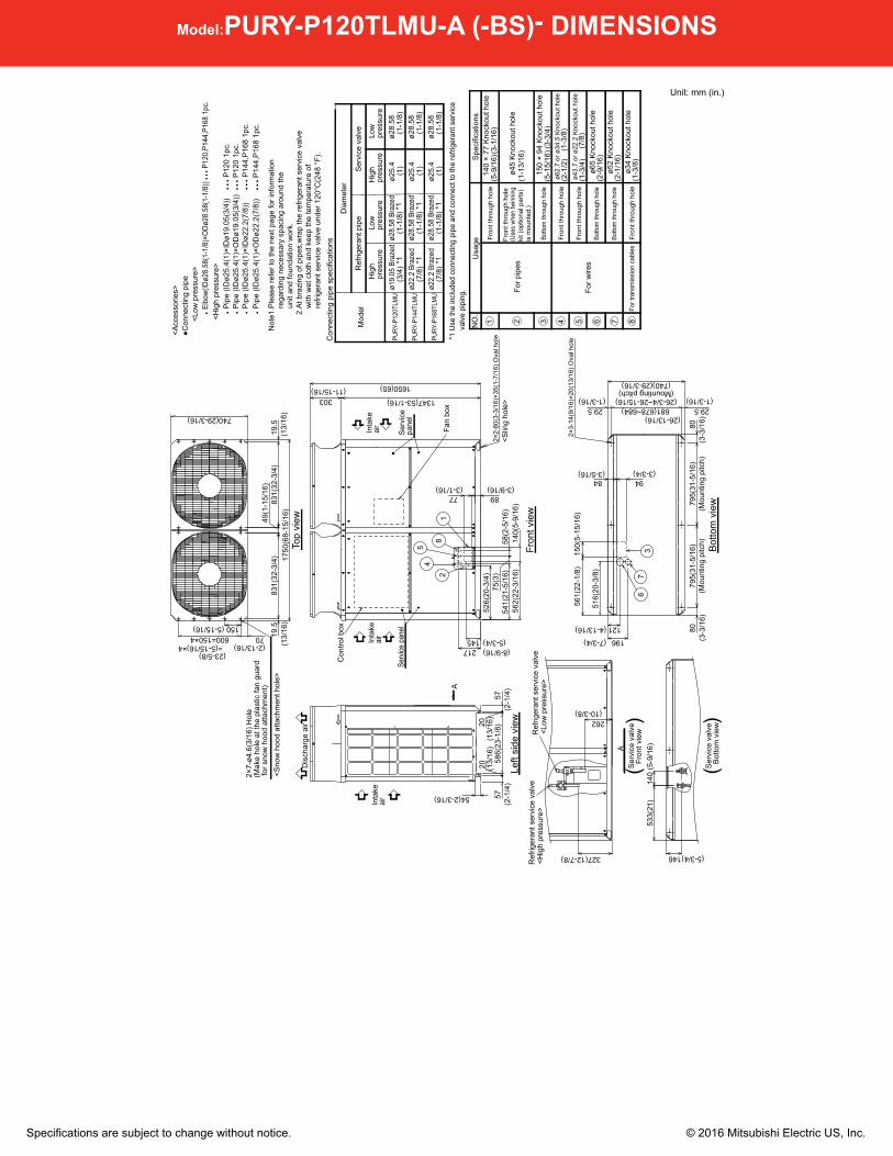
Model:PURY-P120TLMU-A (-BS)- DIMENSIONS
airair
air
Serv
ice p
anel150
(13/
16)
(13/
16)
(2-1
/4)
(2-1
/4)
2×2-
80(3
-3/1
6)×3
5(1-
7/16
) Ova
l hol
e<S
ling
hole
>
Dis
char
ge a
ir
Inta
keIn
take
Ser
vice
pane
l
Inta
ke
2×3-
14(9
/16)
×20(
13/1
6) O
val h
ole
(Mounting pitch)
(Mou
ntin
g pi
tch)
(Mou
ntin
g pi
tch)
Con
trol b
ox
2×7-
ø4.6
(3/1
6) H
ole
(Mak
e ho
le a
t the
pla
stic
fan
guar
d fo
r sno
w h
ood
atta
chm
ent)
<Sno
w h
ood
atta
chm
ent h
ole>
Fan
box
Left
side
vie
wFr
ont v
iew
Top
view
Bot
tom
vie
w
<Hig
h pr
essu
re>
Ref
riger
ant s
ervi
ce v
alve
<L
ow p
ress
ure>
Ref
riger
ant s
ervi
ce v
alve
Fron
t vie
wS
ervi
ce v
alve
Bot
tom
vie
wS
ervi
ce v
alve
A
(
)
(
)
A
(5-3/4)
(5-9
/16)
(10-3/8)
=(5-15/16)×4 (2-13/16)(23-5/8)
(13/
16)
(13/
16)
(11-15/16)
(8-9/16)
(3-9/16)(3-1/16)
(26-3/4~26-15/16)
(26-13/16)
(3-3
/16)
(3-3
/16)
(4-13/16)
(3-5/16)
(1-3/16) (1-3/16)
(3-3/4)
(7-3/4)(5-3/4)
(5-15/16)
Not
e1.P
leas
e re
fer t
o th
e ne
xt p
age
for i
nfor
mat
ion
rega
rdin
g ne
cess
ary
spac
ing
arou
nd th
e
un
it an
d fo
unda
tion
wor
k.
2.A
t bra
zing
of p
ipes
,wra
p th
e re
frige
rant
ser
vice
val
ve
with
wet
clo
th a
nd k
eep
the
tem
pera
ture
of
refri
gera
nt s
ervi
ce v
alve
und
er 1
20°C
(248
°F)
.
<Acc
esso
ries>
●C
onne
ctin
g pi
pe
<Lo
w p
ress
ure>
●
Elb
ow(ID
ø28.
58(1
-1/8
)×O
Dø28
.58(
1-1/
8)) ●
● ● P
120,
P144
,P16
8 1p
c.
<Hig
h pr
essu
re>
● P
ipe
(IDø2
5.4(
1)×I
Dø1
9.05
(3/4
))
● ●
● P12
0 1p
c.
● P
ipe
(IDø2
5.4(
1)×O
Dø1
9.05
(3/4
)) ●
● ● P
120
1pc.
●
Pip
e (ID
ø25.
4(1)
×ID
ø22.
2(7/
8))
●
● ● P
144,
P16
8 1p
c.
● P
ipe
(IDø2
5.4(
1)×O
Dø2
2.2(
7/8)
) ●
● ● P
144,
P16
8 1p
c.
*1 U
se th
e in
clud
ed c
onne
ctin
g pi
pe a
nd c
onne
ct to
the
refri
gera
nt s
ervi
ce
valv
e pi
ping
.
Fron
t thr
ough
hol
e
Botto
m th
roug
h ho
le
Botto
m th
roug
h ho
le
Fron
t thr
ough
hol
e
Fron
t thr
ough
hol
e
For w
ires
ø52
Kno
ckou
t hol
e
For t
rans
mis
sion
cab
les
ø34
Kno
ckou
t hol
e
ø65
Kno
ckou
t hol
e
Botto
m th
roug
h ho
le15
0 ×
94 K
nock
out h
ole
140
× 77
Kno
ckou
t hol
eFr
ont t
hrou
gh h
ole
For p
ipes
Fron
t thr
ough
hol
e(U
ses
when
twin
ning
ki
t (op
tiona
l par
ts)
is m
ount
ed.)
ø45
Kno
ckou
t hol
e
Spe
cific
atio
nsU
sage
ø62.
7 or
ø34
.5 K
nock
out h
ole
ø43.
7 or
ø22
.2 K
nock
out h
ole
Hig
hpr
essu
reLo
wpr
essu
reH
igh
pres
sure
Low
pres
sure
Ser
vice
val
ve
*1 *1*1*1
Ref
riger
ant p
ipe
Dia
met
er
ø25.
4
ø25.
4ø 2
8.58
Bra
zed
PURY
-P14
4TLM
U
PURY
-P12
0TLM
U
ø22.
2 Br
azed
Mod
el
ø 19.
05 B
raze
d
ø28.
58 B
raze
dø2
8.58
ø28.
58
*1*1
ø25.
4PU
RY-P
168T
LMU
ø22.
2 Br
azed
ø28.
58 B
raze
dø2
8.58
(2-9
/16)
(1-3
/8)
(2-1
/16)
(2-1
/2)
(1-3
/4)
(1-3
/8)
(5-1
5/16
)(3-
3/4)
(5-9
/16)
(3-1
/16)
(1-1
3/16
) (7/8
)
(1)
(1)
(1-1
/8)
(7/8
)
(3/4
)
(1-1
/8)
(1-1
/8)
(1-1
/8)
(1)
(7/8
)(1
-1/8
)(1
-1/8
)
Con
nect
ing
pipe
spe
cific
atio
ns
58(2
-5/1
6)75
(3)
54
1(21
-5/1
6)196
121
36
7
29.529.5
562(
22-3
/16)
89
8079
5(31
-5/1
6)79
5(31
-5/1
6)80
681(678~684)
140(
5-9/
16)
150(
5-15
/16)
561(
22-1
/8)
516(
20-3
/8)
84 94
533(
21)
146327(12-7/8)
262
140
526(
20-3
/4)
217
303
1
5
8
1347(53-1/16)
1650(65)
1750
(68-
15/1
6)19
.583
1(32
-3/4
)83
1(32
-3/4
)19
.5
600=150×4 70
(740)(29-3/16)
740(29-3/16)
77
49(1
-15/
16)
54(2-3/16) 57
20
586(
23-1
/8)
57
20
4
2
145
1 2 43 5 6 7NO
.
8
Unit: mm (in.)

Specifications are subject to change without notice. © 2016 Mitsubishi Electric US, Inc.
Twinning Kit:CMY-ER200CBK- DIMENSIONS
<Accessory>
Pipe cover • • • 1Fixing screw • • • 1
Cable tie • • • 2Insulation cover • • • 1
(Outside diameter)
(Outside diameter)
(Outside diameter)
(Outside diameter)
High-pressure twinning pipe
Low-pressure pipe twinning kit
<Elbow pipe(Accessory)>
<Deformed pipe(Accessory)>
<Deformed pipe(Accessory)>
<Pipe for routing through the front (Accessory)>
(Outside diameter)
(Outside diameter)
(Outside diameter)
<Pipe for routing through the bottom (Accessory)>
(Outside diameter)
(Outside diameter)
(Outside diameter)
(Outside diameter)
(Outside diameter)
(Outside diameter)
(Outside diameter)
108(4-5/16)
32
26(1-1/16)
62 176(
6-15
/16)
427(16-13/16)
ø31.75(ø1-1/4)
ø28.58(ø1-1/8)
ø28.58(ø1-1/8)
69
62
ø22.2(ø7/8)
ø34.93(ø1-3/8)
ø19.05(ø3/4)
ø41.28(ø1-5/8)
160(6-5/16)50(2)
50(2
)
35
80
53
53
62
ø28.58(ø1-1/8)ø28.58(ø1-1/8)
ø19.05(ø3/4)
ø19.05(ø3/4)ø28.58(ø1-1/8)
ø31.75(ø1-1/4)ø31.75(ø1-1/4)
ø19.05(ø3/4) ø22.2(ø7/8)
ø34.93(ø1-3/8)ø31.75(ø1-1/4)
ø25.4(ø1)
ø19.05(ø3/4)ø25.4(ø1)
ø19.05(ø3/4)
303(11-15/16)
55
182(7-3/16)
100(
3-15
/16)
62
62
69
ø22.2(ø7/8)
ø31.75(ø1-1/4) ø28.58(ø1-1/8)
ø22.2(ø7/8) ø28.58(ø1-1/8)
ø28.58(ø1-1/8)
25
136(5-3/8)
35
ø22.2(ø7/8)
ø19.05(ø3/4)
ø19.05(ø3/4)
62
ø22.2(ø7/8)
62
62
ø15.88(ø5/8)ø19.05(ø3/4)
62
ø22.2(ø7/8)ø28.58(ø1-1/8)
(1) (1-7/16)
(2-1
/2)(
1-5/
16)
(2-1/2)
(2-1/2)
(2-3/4)
(2-1/8)
(2-1
/8)
(2-1/2)
(2-3/4)
(2-1/2)
(1-7
/16)
(3-3/16)
(2-1/2)
(2-1/2)
(2-1/2)
(2-1/2)
(3Pcs.)
(2-3
/16)
high-pressure side
Slope of the twinning pipe is at an anglewithin ±15° to the horizontal plane.
Note 1:Refer to the figure below for the installationposition of the twinning pipe.
2:Pipe diameter is indicated by inside diameter.
Twinning pipe on the
±15°
Unit: mm (in.)
1340 Satellite Boulevard. Suwanee, GA 30024Toll Free: 800-433-4822 www.mehvac.com
Variable Refrigerant Flow (VRF) Multi-Split AC and HPAHRI Standard 1230
FORM# PURY-P240TSLMU-A (-BS) -20160224