SUBMITTAL DATA: MXZ-4C36NAHZ M-SERIES …meus1.mylinkdrive.com/files/MXZ-4C36NAHZ_Submittal.pdf ·...
10
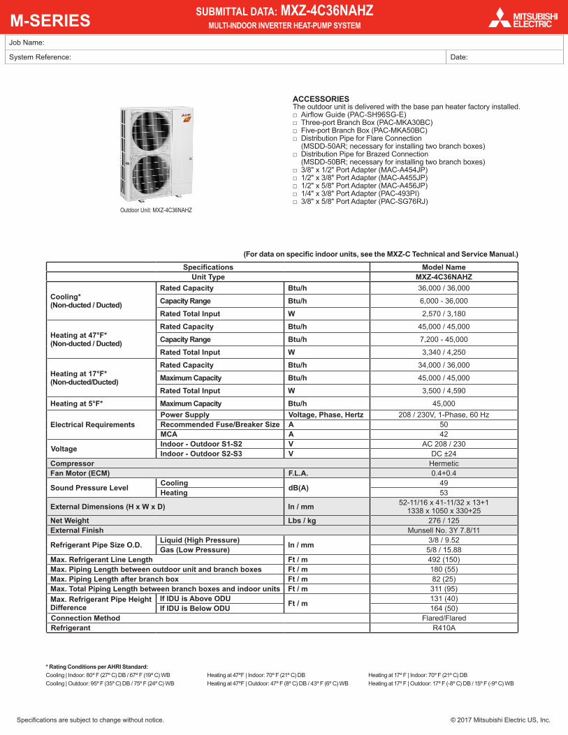
M-SERIES Specifications are subject to change without notice. © 2017 Mitsubishi Electric US, Inc. Job Name: System Reference: Date: SUBMITTAL DATA: MXZ-4C36NAHZ MULTI-INDOOR INVERTER HEAT-PUMP SYSTEM Specifications Model Name Unit Type MXZ-4C36NAHZ Cooling* (Non-ducted / Ducted) Rated Capacity Btu/h 36,000 / 36,000 Capacity Range Btu/h 6,000 - 36,000 Rated Total Input W 2,570 / 3,180 Heating at 47°F* (Non-ducted / Ducted) Rated Capacity Btu/h 45,000 / 45,000 Capacity Range Btu/h 7,200 - 45,000 Rated Total Input W 3,340 / 4,250 Heating at 17°F* (Non-ducted/Ducted) Rated Capacity Btu/h 34,000 / 36,000 Maximum Capacity Btu/h 45,000 / 45,000 Rated Total Input W 3,500 / 4,590 Heating at 5°F* Maximum Capacity Btu/h 45,000 Electrical Requirements Power Supply Voltage, Phase, Hertz 208 / 230V, 1-Phase, 60 Hz Recommended Fuse/Breaker Size A 50 MCA A 42 Voltage Indoor - Outdoor S1-S2 V AC 208 / 230 Indoor - Outdoor S2-S3 V DC ±24 Compressor Hermetic Fan Motor (ECM) F.L.A. 0.4+0.4 Sound Pressure Level Cooling dB(A) 49 Heating 53 External Dimensions (H x W x D) In / mm 52-11/16 x 41-11/32 x 13+1 1338 x 1050 x 330+25 Net Weight Lbs / kg 276 / 125 External Finish Munsell No. 3Y 7.8/11 Refrigerant Pipe Size O.D. Liquid (High Pressure) In / mm 3/8 / 9.52 Gas (Low Pressure) 5/8 / 15.88 Max. Refrigerant Line Length Ft / m 492 (150) Max. Piping Length between outdoor unit and branch boxes Ft / m 180 (55) Max. Piping Length after branch box Ft / m 82 (25) Max. Total Piping Length between branch boxes and indoor units Ft / m 311 (95) Max. Refrigerant Pipe Height Difference If IDU is Above ODU Ft / m 131 (40) If IDU is Below ODU 164 (50) Connection Method Flared/Flared Refrigerant R410A * Rating Conditions per AHRI Standard: Cooling | Indoor: 80º F (27º C) DB / 67º F (19º C) WB Cooling | Outdoor: 95º F (35º C) DB / 75º F (24º C) WB Heating at 47ºF | Indoor: 70º F (21º C) DB Heating at 47ºF | Outdoor: 47º F (8º C) DB / 43º F (6º C) WB Heating at 17º F | Indoor: 70º F (21º C) DB Heating at 17º F | Outdoor: 17º F (-8º C) DB / 15º F (-9º C) WB ACCESSORIES The outdoor unit is delivered with the base pan heater factory installed. □ Airflow Guide (PAC-SH96SG-E) □ Three-port Branch Box (PAC-MKA30BC) □ Five-port Branch Box (PAC-MKA50BC) □ Distribution Pipe for Flare Connection (MSDD-50AR; necessary for installing two branch boxes) □ Distribution Pipe for Brazed Connection (MSDD-50BR; necessary for installing two branch boxes) □ 3/8" x 1/2" Port Adapter (MAC-A454JP) □ 1/2" x 3/8" Port Adapter (MAC-A455JP) □ 1/2" x 5/8" Port Adapter (MAC-A456JP) □ 1/4" x 3/8" Port Adapter (PAC-493PI) □ 3/8" x 5/8" Port Adapter (PAC-SG76RJ) Outdoor Unit: MXZ-4C36NAHZ (For data on specific indoor units, see the MXZ-C Technical and Service Manual.)
Transcript of SUBMITTAL DATA: MXZ-4C36NAHZ M-SERIES …meus1.mylinkdrive.com/files/MXZ-4C36NAHZ_Submittal.pdf ·...
M-SERIES
Specifications are subject to change without notice. © 2017 Mitsubishi Electric US, Inc.
Job Name:
System Reference: Date:
SUBMITTAL DATA: MXZ-4C36NAHZMULTI-INDOOR INVERTER HEAT-PUMP SYSTEM
Specifications Model NameUnit Type MXZ-4C36NAHZ
Cooling* (Non-ducted / Ducted)
Rated Capacity Btu/h 36,000 / 36,000
Capacity Range Btu/h 6,000 - 36,000
Rated Total Input W 2,570 / 3,180
Heating at 47°F* (Non-ducted / Ducted)
Rated Capacity Btu/h 45,000 / 45,000
Capacity Range Btu/h 7,200 - 45,000
Rated Total Input W 3,340 / 4,250
Heating at 17°F* (Non-ducted/Ducted)
Rated Capacity Btu/h 34,000 / 36,000
Maximum Capacity Btu/h 45,000 / 45,000
Rated Total Input W 3,500 / 4,590
Heating at 5°F* Maximum Capacity Btu/h 45,000
Electrical RequirementsPower Supply Voltage, Phase, Hertz 208 / 230V, 1-Phase, 60 HzRecommended Fuse/Breaker Size A 50MCA A 42
Voltage Indoor - Outdoor S1-S2 V AC 208 / 230Indoor - Outdoor S2-S3 V DC ±24
Compressor HermeticFan Motor (ECM) F.L.A. 0.4+0.4
Sound Pressure Level Cooling dB(A) 49Heating 53
External Dimensions (H x W x D) In / mm 52-11/16 x 41-11/32 x 13+1 1338 x 1050 x 330+25
Net Weight Lbs / kg 276 / 125External Finish Munsell No. 3Y 7.8/11
Refrigerant Pipe Size O.D. Liquid (High Pressure) In / mm 3/8 / 9.52Gas (Low Pressure) 5/8 / 15.88
Max. Refrigerant Line Length Ft / m 492 (150)Max. Piping Length between outdoor unit and branch boxes Ft / m 180 (55)Max. Piping Length after branch box Ft / m 82 (25)Max. Total Piping Length between branch boxes and indoor units Ft / m 311 (95)Max. Refrigerant Pipe Height Difference
If IDU is Above ODU Ft / m 131 (40)If IDU is Below ODU 164 (50)
Connection Method Flared/FlaredRefrigerant R410A
* Rating Conditions per AHRI Standard: Cooling | Indoor: 80º F (27º C) DB / 67º F (19º C) WB Cooling | Outdoor: 95º F (35º C) DB / 75º F (24º C) WB
Heating at 47ºF | Indoor: 70º F (21º C) DB Heating at 47ºF | Outdoor: 47º F (8º C) DB / 43º F (6º C) WB
Heating at 17º F | Indoor: 70º F (21º C) DB Heating at 17º F | Outdoor: 17º F (-8º C) DB / 15º F (-9º C) WB
ACCESSORIESThe outdoor unit is delivered with the base pan heater factory installed.
□ Airflow Guide (PAC-SH96SG-E) □ Three-port Branch Box (PAC-MKA30BC) □ Five-port Branch Box (PAC-MKA50BC) □ Distribution Pipe for Flare Connection (MSDD-50AR; necessary for installing two branch boxes)
□ Distribution Pipe for Brazed Connection (MSDD-50BR; necessary for installing two branch boxes)
□ 3/8" x 1/2" Port Adapter (MAC-A454JP) □ 1/2" x 3/8" Port Adapter (MAC-A455JP) □ 1/2" x 5/8" Port Adapter (MAC-A456JP) □ 1/4" x 3/8" Port Adapter (PAC-493PI) □ 3/8" x 5/8" Port Adapter (PAC-SG76RJ)
Outdoor Unit: MXZ-4C36NAHZ
(For data on specific indoor units, see the MXZ-C Technical and Service Manual.)
Specifications are subject to change without notice. © 2017 Mitsubishi Electric US, Inc.
Notes:
SPECIFICATIONS: MXZ-4C36NAHZ, contd.
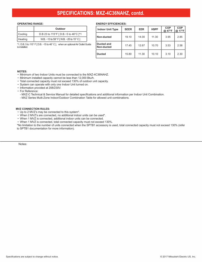
• Minimum of two Indoor Units must be connected to the MXZ-4C36NAHZ.• Minimum installed capacity cannot be less than 12,000 Btu/h. • Total connected capacity must not exceed 130% of outdoor unit capacity.• System can operate with only one Indoor Unit turned on. • Information provided at 208/230V. • For Reference:
- MXZ-C Technical & Service Manual for detailed specifications and additional information per Indoor Unit Combination. - MXZ Series Multi-Zone Indoor/Outdoor Combination Table for allowed unit combinations.
Indoor Unit Type SEER EER HSPF COP @ 47°F
COP @ 17°F
Non-ducted 19.10 14.00 11.30 3.95 2.85
Ducted and Non-ducted 17.45 12.67 10.70 3.53 2.58
Ducted 15.80 11.30 10.10 3.10 2.30
• Up to 2 MVZ’s may be connected to this system*. • When 2 MVZ’s are connected, no additional indoor units can be used*. • When 1 MVZ is connected, additional indoor units can be connected. • When 1 MVZ is connected, total connected capacity must not exceed 130%. *No limitation to the number of units connected when the SPTB1 accessory is used, total connected capacity must not exceed 130% (refer to SPTB1 documentation for more information).
Outdoor
Cooling D.B 23 to 115°F [ D.B.−5 to 46°C ]*1
Heating W.B. −13 to 59° F [ W.B. −25 to 15° C ]
*1. D.B. 5 to 115° F [ D.B. −15 to 46° C ], when an optional Air Outlet Guide is installed.
ENERGY EFFICIENCIES:
NOTES:
OPERATING RANGE:
MVZ CONNECTION RULES:
Specifications are subject to change without notice. © 2017 Mitsubishi Electric US, Inc.
MXZ-4C36NAHZ SYSTEM DESIGN
5
2
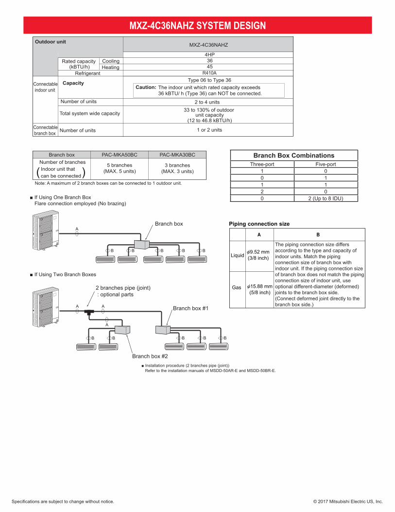
MXZ-4C36NAHZ
Heating
Rated capacity (kBTU/h)
R410A
Connectableindoor unit
Capacity
Number of units
Total system wide capacity
Type 06 to Type 36
1 or 2 unitsNumber of units
Outdoor unit
Branch box PAC-MKA50BC
5 branches(MAX. 5 units)
PAC-MKA30BC
3 branches(MAX. 3 units)
Number of branches Indoor unit that can be connected( )
Note: A maximum of 2 branch boxes can be connected to 1 outdoor unit.
Select a model according to the connection method.
2- branch pipe (joint): Optional partsIn case of using 1- branch box
In case of using 2- branch boxes
No need
Model name Connection methodflare
brazingMSDD-50AR-EMSDD-50BR-E
Option Optional accessories for indoor units and outdoor units are available.
Ceilingconcealed4-way ceiling cassette
Wallmounted
Model type Model name
Deluxe
StandardLow static pressureMiddle static pressure2 by 2 typeStandard
MSZ-FE09/12/18NAMSZ-FH09/12/15NAMSZ-GE06/09/12/15/18/24NASEZ-KD09/12/15/18NAPEAD-A24/30/36AA4SLZ-KA09/12/15NAPLA-A12/18/24/30/36BA4MFZ-KA09/12/18NAMVZ-A12/18/24/30/36AA4
Floor standing
Capacity class [kBTU/h]06
Connectable indoor unit lineups (Heat pump inverter type)
Cooling
Refrigerant
4HP3645
Caution: The indoor unit which rated capacity exceeds 36 kBTU/ h (Type 36) can NOT be connected.
2 to 4 units33 to 130% of outdoor
unit capacity(12 to 46.8 kBTU/h)
Connectablebranch box
09 12 15 18 24 30 36
Multi-position
OCH573
8
A
B B B B B
Branch box
■ If Using One Branch Box Flare connection employed (No brazing)
A A
A
B B B B B
2 branches pipe (joint) : optional parts
Branch box #1
Branch box #2
■ If Using Two Branch Boxes
■ Installation procedure (2 branches pipe (joint))Refer to the installation manuals of MSDD-50AR-E and MSDD-50BR-E.
OCH573
Branch Box CombinationsThree-port Five-port
1 00 11 12 00 2 (Up to 8 IDU)
The piping connection size differs according to the type and capacity of indoor units. Match the piping connection size of branch box with indoor unit. If the piping connection size of branch box does not match the piping connection size of indoor unit, use optional different-diameter (deformed) joints to the branch box side. (Connect deformed joint directly to the branch box side.)
5
2
MXZ-4C36NAHZ
Heating
Rated capacity (kBTU/h)
R410A
Connectableindoor unit
Capacity
Number of units
Total system wide capacity
Type 06 to Type 36
1 or 2 unitsNumber of units
Outdoor unit
Branch box PAC-MKA50BC
5 branches(MAX. 5 units)
PAC-MKA30BC
3 branches(MAX. 3 units)
Number of branches Indoor unit that can be connected( )
Note: A maximum of 2 branch boxes can be connected to 1 outdoor unit.
Select a model according to the connection method.
2- branch pipe (joint): Optional partsIn case of using 1- branch box
In case of using 2- branch boxes
No need
Model name Connection methodflare
brazingMSDD-50AR-EMSDD-50BR-E
Option Optional accessories for indoor units and outdoor units are available.
Ceilingconcealed4-way ceiling cassette
Wallmounted
Model type Model name
Deluxe
StandardLow static pressureMiddle static pressure2 by 2 typeStandard
MSZ-FE09/12/18NAMSZ-FH09/12/15NAMSZ-GE06/09/12/15/18/24NASEZ-KD09/12/15/18NAPEAD-A24/30/36AA4SLZ-KA09/12/15NAPLA-A12/18/24/30/36BA4MFZ-KA09/12/18NAMVZ-A12/18/24/30/36AA4
Floor standing
Capacity class [kBTU/h]06
Connectable indoor unit lineups (Heat pump inverter type)
Cooling
Refrigerant
4HP3645
Caution: The indoor unit which rated capacity exceeds 36 kBTU/ h (Type 36) can NOT be connected.
2 to 4 units33 to 130% of outdoor
unit capacity(12 to 46.8 kBTU/h)
Connectablebranch box
09 12 15 18 24 30 36
Multi-position
OCH573
Specifications are subject to change without notice. © 2017 Mitsubishi Electric US, Inc.
MXZ-4C36NAHZ COOLING AND HEATING CAPACITY AND CHARACTERISTICS4
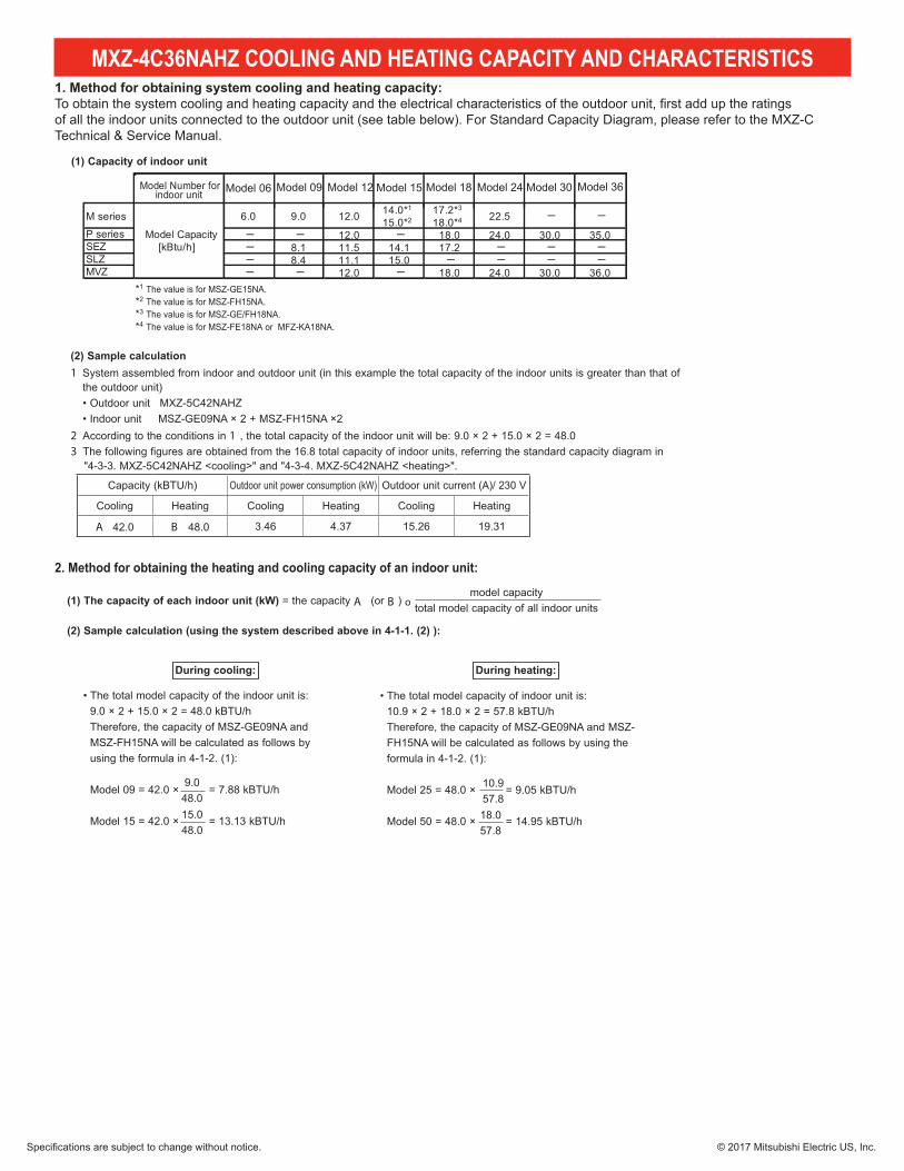
4-1. COOLING AND HEATING CAPACITY AND CHARACTERISTICS1. Method for obtaining system cooling and heating capacity:
(1) Capacity of indoor unit
2. Method for obtaining the heating and cooling capacity of an indoor unit:
(1) The capacity of each indoor unit (kW) A B o
(2) Sample calculation (using the system described above in 4-1-1. (2) ):
During cooling: During heating:
(2) Sample calculation1
2 13
Model Number forindoor unit Model 06
M series 6.0 9.0 12.0 14.0*1
15.0*217.2*3
18.0*4 22.5 ─ ─
P series ─ ─ 12.0 ─ 18.0 24.0 30.0 35.0SEZ ─ 8.1 11.5 14.1 17.2 ─ ─ ─SLZ ─ 8.4 11.1 15.0 ─ ─ ─ ─MVZ ─ ─ 12.0 ─ 18.0 24.0 30.0 36.0
Model Capacity[kBtu/h]
Model 09 Model 12 Model 15 Model 18 Model 24 Model 30 Model 36
*1 The value is for MSZ-GE15NA.*2 The value is for MSZ-FH15NA.*3 The value is for MSZ-GE/FH18NA.*4 The value is for MSZ-FE18NA or MFZ-KA18NA.
A B
DATA
OCH573
1. Method for obtaining system cooling and heating capacity:To obtain the system cooling and heating capacity and the electrical characteristics of the outdoor unit, first add up the ratingsof all the indoor units connected to the outdoor unit (see table below). For Standard Capacity Diagram, please refer to the MXZ-C Technical & Service Manual.
2. Method for obtaining the heating and cooling capacity of an indoor unit:
Specifications are subject to change without notice. © 2017 Mitsubishi Electric US, Inc.
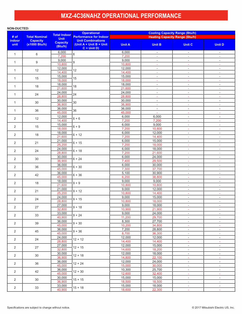
MXZ-4C36NAHZ OPERATIONAL PERFORMANCE
NON-DUCTED:
# of indoor
unit
Total Nominal Capacity
(x1000 Btu/h)
Total Indoor Unit
Capacity (Btu/h)
Operational Performance for Indoor
Unit Combinations(Unit A + Unit B + Unit
C + Unit D)
Cooling Capacity Range (Btu/h)Heating Capacity Range (Btu/h)
Unit A Unit B Unit C Unit D
1 6 6,000 6 6,000 - - - 7,200 7,200 - - -
1 9 9,000 9 9,000 - - - 10,800 10,800 - - -
1 12 12,000 12 12,000 - - - 14,400 14,400 - - -
1 15 15,000 15 15,000 - - - 18,000 18,000 - - -
1 18 18,000 18 18,000 - - - 21,600 21,600 - - -
1 24 24,000 24 24,000 - - - 28,800 28,800 - - -
1 30 30,000 30 30,000 - - - 36,900 36,900 - - -
1 36 36,000 36 36,000 - - - 45,000 45,000 - - -
2 12 12,000 6 + 6 6,000 6,000 - - 14,400 7,200 7,200 - -
2 15 15,000 6 + 9 6,000 9,000 - - 18,000 7,200 10,800 - -
2 18 18,000 6 + 12 6,000 12,000 - - 21,600 7,200 14,400 - -
2 21 21,000 6 + 15 6,000 15,000 - - 25,200 7,200 18,000 - -
2 24 24,000 6 + 18 6,000 18,000 - - 28,800 7,200 21,600 - -
2 30 30,000 6 + 24 6,000 24,000 - - 36,900 7,400 29,500 - -
2 36 36,000 6 + 30 6,000 30,000 - - 45,000 7,300 37,700 - -
2 42 36,000 6 + 36 5,100 30,900 - - 45,000 6,200 38,800 - -
2 18 18,000 9 + 9 9,000 9,000 - - 21,600 10,800 10,800 - -
2 21 21,000 9 + 12 9,000 12,000 - - 25,200 10,800 14,400 - -
2 24 24,000 9 + 15 9,000 15,000 - - 28,800 10,800 18,000 - -
2 27 27,000 9 + 18 9,000 18,000 - - 32,800 10,900 21,900 - -
2 33 33,000 9 + 24 9,000 24,000 - - 40,900 11,200 29,700 - -
2 39 36,000 9 + 30 8,300 27,700 - - 45,000 10,200 34,800 - -
2 45 36,000 9 + 36 7,200 28,800 - - 45,000 8,700 36,300 - -
2 24 24,000 12 + 12 12,000 12,000 - - 28,800 14,400 14,400 - -
2 27 27,000 12 + 15 12,000 15,000 - - 32,800 14,600 18,200 - -
2 30 30,000 12 + 18 12,000 18,000 - - 36,900 14,800 22,100 - -
2 36 36,000 12 + 24 12,000 24,000 - - 45,000 15,000 30,000 - -
2 42 36,000 12 + 30 10,300 25,700 - - 45,000 12,600 32,400 - -
2 30 30,000 15 + 15 15,000 15,000 - - 36,900 18,500 18,500 - -
2 33 33,000 15 + 18 15,000 18,000 - - 40,900 18,600 22,300 - -
Specifications are subject to change without notice. © 2017 Mitsubishi Electric US, Inc.
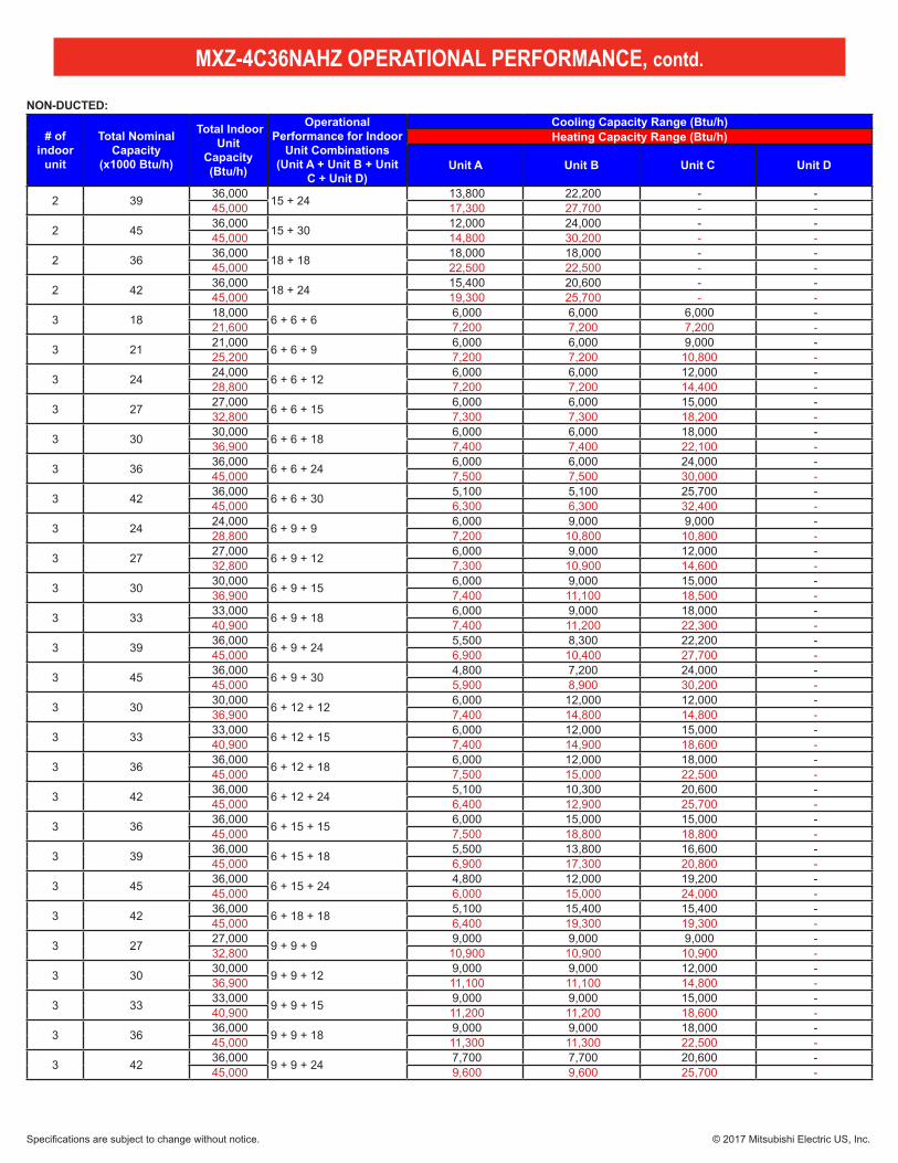
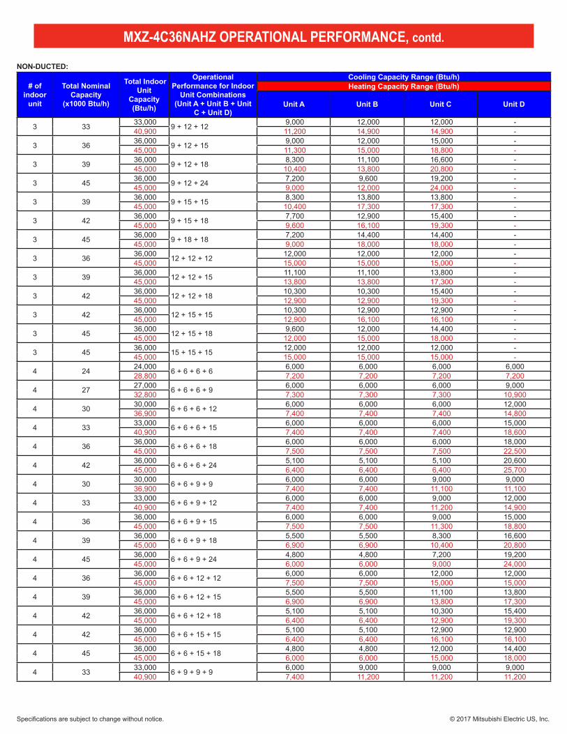
MXZ-4C36NAHZ OPERATIONAL PERFORMANCE, contd.
# of indoor
unit
Total Nominal Capacity
(x1000 Btu/h)
Total Indoor Unit
Capacity (Btu/h)
Operational Performance for Indoor
Unit Combinations(Unit A + Unit B + Unit
C + Unit D)
Cooling Capacity Range (Btu/h)Heating Capacity Range (Btu/h)
Unit A Unit B Unit C Unit D
2 39 36,000 15 + 24 13,800 22,200 - - 45,000 17,300 27,700 - -
2 45 36,000 15 + 30 12,000 24,000 - - 45,000 14,800 30,200 - -
2 36 36,000 18 + 18 18,000 18,000 - - 45,000 22,500 22,500 - -
2 42 36,000 18 + 24 15,400 20,600 - - 45,000 19,300 25,700 - -
3 18 18,000 6 + 6 + 6 6,000 6,000 6,000 - 21,600 7,200 7,200 7,200 -
3 21 21,000 6 + 6 + 9 6,000 6,000 9,000 - 25,200 7,200 7,200 10,800 -
3 24 24,000 6 + 6 + 12 6,000 6,000 12,000 - 28,800 7,200 7,200 14,400 -
3 27 27,000 6 + 6 + 15 6,000 6,000 15,000 - 32,800 7,300 7,300 18,200 -
3 30 30,000 6 + 6 + 18 6,000 6,000 18,000 - 36,900 7,400 7,400 22,100 -
3 36 36,000 6 + 6 + 24 6,000 6,000 24,000 - 45,000 7,500 7,500 30,000 -
3 42 36,000 6 + 6 + 30 5,100 5,100 25,700 - 45,000 6,300 6,300 32,400 -
3 24 24,000 6 + 9 + 9 6,000 9,000 9,000 - 28,800 7,200 10,800 10,800 -
3 27 27,000 6 + 9 + 12 6,000 9,000 12,000 - 32,800 7,300 10,900 14,600 -
3 30 30,000 6 + 9 + 15 6,000 9,000 15,000 - 36,900 7,400 11,100 18,500 -
3 33 33,000 6 + 9 + 18 6,000 9,000 18,000 - 40,900 7,400 11,200 22,300 -
3 39 36,000 6 + 9 + 24 5,500 8,300 22,200 - 45,000 6,900 10,400 27,700 -
3 45 36,000 6 + 9 + 30 4,800 7,200 24,000 - 45,000 5,900 8,900 30,200 -
3 30 30,000 6 + 12 + 12 6,000 12,000 12,000 - 36,900 7,400 14,800 14,800 -
3 33 33,000 6 + 12 + 15 6,000 12,000 15,000 - 40,900 7,400 14,900 18,600 -
3 36 36,000 6 + 12 + 18 6,000 12,000 18,000 - 45,000 7,500 15,000 22,500 -
3 42 36,000 6 + 12 + 24 5,100 10,300 20,600 - 45,000 6,400 12,900 25,700 -
3 36 36,000 6 + 15 + 15 6,000 15,000 15,000 - 45,000 7,500 18,800 18,800 -
3 39 36,000 6 + 15 + 18 5,500 13,800 16,600 - 45,000 6,900 17,300 20,800 -
3 45 36,000 6 + 15 + 24 4,800 12,000 19,200 - 45,000 6,000 15,000 24,000 -
3 42 36,000 6 + 18 + 18 5,100 15,400 15,400 - 45,000 6,400 19,300 19,300 -
3 27 27,000 9 + 9 + 9 9,000 9,000 9,000 - 32,800 10,900 10,900 10,900 -
3 30 30,000 9 + 9 + 12 9,000 9,000 12,000 - 36,900 11,100 11,100 14,800 -
3 33 33,000 9 + 9 + 15 9,000 9,000 15,000 - 40,900 11,200 11,200 18,600 -
3 36 36,000 9 + 9 + 18 9,000 9,000 18,000 - 45,000 11,300 11,300 22,500 -
3 42 36,000 9 + 9 + 24 7,700 7,700 20,600 - 45,000 9,600 9,600 25,700 -
NON-DUCTED:
Specifications are subject to change without notice. © 2017 Mitsubishi Electric US, Inc.
MXZ-4C36NAHZ OPERATIONAL PERFORMANCE, contd.
# of indoor
unit
Total Nominal Capacity
(x1000 Btu/h)
Total Indoor Unit
Capacity (Btu/h)
Operational Performance for Indoor
Unit Combinations(Unit A + Unit B + Unit
C + Unit D)
Cooling Capacity Range (Btu/h)Heating Capacity Range (Btu/h)
Unit A Unit B Unit C Unit D
3 33 33,000 9 + 12 + 12 9,000 12,000 12,000 - 40,900 11,200 14,900 14,900 -
3 36 36,000 9 + 12 + 15 9,000 12,000 15,000 - 45,000 11,300 15,000 18,800 -
3 39 36,000 9 + 12 + 18 8,300 11,100 16,600 - 45,000 10,400 13,800 20,800 -
3 45 36,000 9 + 12 + 24 7,200 9,600 19,200 - 45,000 9,000 12,000 24,000 -
3 39 36,000 9 + 15 + 15 8,300 13,800 13,800 - 45,000 10,400 17,300 17,300 -
3 42 36,000 9 + 15 + 18 7,700 12,900 15,400 - 45,000 9,600 16,100 19,300 -
3 45 36,000 9 + 18 + 18 7,200 14,400 14,400 - 45,000 9,000 18,000 18,000 -
3 36 36,000 12 + 12 + 12 12,000 12,000 12,000 - 45,000 15,000 15,000 15,000 -
3 39 36,000 12 + 12 + 15 11,100 11,100 13,800 - 45,000 13,800 13,800 17,300 -
3 42 36,000 12 + 12 + 18 10,300 10,300 15,400 - 45,000 12,900 12,900 19,300 -
3 42 36,000 12 + 15 + 15 10,300 12,900 12,900 - 45,000 12,900 16,100 16,100 -
3 45 36,000 12 + 15 + 18 9,600 12,000 14,400 - 45,000 12,000 15,000 18,000 -
3 45 36,000 15 + 15 + 15 12,000 12,000 12,000 - 45,000 15,000 15,000 15,000 -
4 24 24,000 6 + 6 + 6 + 6 6,000 6,000 6,000 6,000 28,800 7,200 7,200 7,200 7,200
4 27 27,000 6 + 6 + 6 + 9 6,000 6,000 6,000 9,000 32,800 7,300 7,300 7,300 10,900
4 30 30,000 6 + 6 + 6 + 12 6,000 6,000 6,000 12,000 36,900 7,400 7,400 7,400 14,800
4 33 33,000 6 + 6 + 6 + 15 6,000 6,000 6,000 15,000 40,900 7,400 7,400 7,400 18,600
4 36 36,000 6 + 6 + 6 + 18 6,000 6,000 6,000 18,000 45,000 7,500 7,500 7,500 22,500
4 42 36,000 6 + 6 + 6 + 24 5,100 5,100 5,100 20,600 45,000 6,400 6,400 6,400 25,700
4 30 30,000 6 + 6 + 9 + 9 6,000 6,000 9,000 9,000 36,900 7,400 7,400 11,100 11,100
4 33 33,000 6 + 6 + 9 + 12 6,000 6,000 9,000 12,000 40,900 7,400 7,400 11,200 14,900
4 36 36,000 6 + 6 + 9 + 15 6,000 6,000 9,000 15,000 45,000 7,500 7,500 11,300 18,800
4 39 36,000 6 + 6 + 9 + 18 5,500 5,500 8,300 16,600 45,000 6,900 6,900 10,400 20,800
4 45 36,000 6 + 6 + 9 + 24 4,800 4,800 7,200 19,200 45,000 6,000 6,000 9,000 24,000
4 36 36,000 6 + 6 + 12 + 12 6,000 6,000 12,000 12,000 45,000 7,500 7,500 15,000 15,000
4 39 36,000 6 + 6 + 12 + 15 5,500 5,500 11,100 13,800 45,000 6,900 6,900 13,800 17,300
4 42 36,000 6 + 6 + 12 + 18 5,100 5,100 10,300 15,400 45,000 6,400 6,400 12,900 19,300
4 42 36,000 6 + 6 + 15 + 15 5,100 5,100 12,900 12,900 45,000 6,400 6,400 16,100 16,100
4 45 36,000 6 + 6 + 15 + 18 4,800 4,800 12,000 14,400 45,000 6,000 6,000 15,000 18,000
4 33 33,000 6 + 9 + 9 + 9 6,000 9,000 9,000 9,000 40,900 7,400 11,200 11,200 11,200
NON-DUCTED:
Specifications are subject to change without notice. © 2017 Mitsubishi Electric US, Inc.
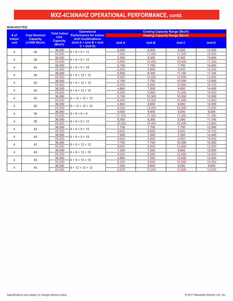
MXZ-4C36NAHZ OPERATIONAL PERFORMANCE, contd.
# of indoor
unit
Total Nominal Capacity
(x1000 Btu/h)
Total Indoor Unit
Capacity (Btu/h)
Operational Performance for Indoor
Unit Combinations(Unit A + Unit B + Unit
C + Unit D)
Cooling Capacity Range (Btu/h)Heating Capacity Range (Btu/h)
Unit A Unit B Unit C Unit D
4 36 36,000 6 + 9 + 9 + 12 6,000 9,000 9,000 12,000 45,000 7,500 11,300 11,300 15,000
4 39 36,000 6 + 9 + 9 + 15 5,500 8,300 8,300 13,800 45,000 6,900 10,400 10,400 17,300
4 42 36,000 6 + 9 + 9 + 18 5,100 7,700 7,700 15,400 45,000 6,400 9,600 9,600 19,300
4 39 36,000 6 + 9 + 12 + 12 5,500 8,300 11,100 11,100 45,000 6,900 10,400 13,800 13,800
4 42 36,000 6 + 9 + 12 + 15 5,100 7,700 10,300 12,900 45,000 6,400 9,600 12,900 16,100
4 45 36,000 6 + 9 + 12 + 18 4,800 7,200 9,600 14,400 45,000 6,000 9,000 12,000 18,000
4 42 36,000 6 + 12 + 12 + 12 5,100 10,300 10,300 10,300 45,000 6,400 12,900 12,900 12,900
4 45 36,000 6 + 12 + 12 + 15 4,800 9,600 9,600 12,000 45,000 6,000 12,000 12,000 15,000
4 36 36,000 9 + 9 + 9 + 9 9,000 9,000 9,000 9,000 45,000 11,300 11,300 11,300 11,300
4 39 36,000 9 + 9 + 9 + 12 8,300 8,300 8,300 11,100 45,000 10,400 10,400 10,400 13,800
4 42 36,000 9 + 9 + 9 + 15 7,700 7,700 7,700 12,900 45,000 9,600 9,600 9,600 16,100
4 45 36,000 9 + 9 + 9 + 18 7,200 7,200 7,200 14,400 45,000 9,000 9,000 9,000 18,000
4 42 36,000 9 + 9 + 12 + 12 7,700 7,700 10,300 10,300 45,000 9,600 9,600 12,900 12,900
4 45 36,000 9 + 9 + 12 + 15 7,200 7,200 9,600 12,000 45,000 9,000 9,000 12,000 15,000
4 45 36,000 6 + 9 + 15 + 15 4,800 7,200 12,000 12,000 45,000 6,000 9,000 15,000 15,000
4 45 36,000 9 + 12 + 12 + 12 7,200 9,600 9,600 9,600 45,000 9,000 12,000 12,000 12,000
NON-DUCTED:
Specifications are subject to change without notice. © 2017 Mitsubishi Electric US, Inc.
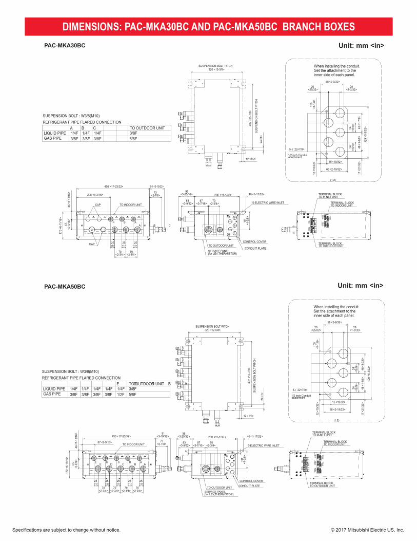
DIMENSIONS: PAC-MKA30BC AND PAC-MKA50BC BRANCH BOXESPAC-MKA30BC
PAC-MKA50BC 24
TO INDOOR UNIT
AA B C
BC
CAP
CAP
25<1>
73<2-7/8>
91 <3-19/32>
170
<6-1
1/16
>
46<1
-13/
16>
65<2
-9/1
6>
25<1>
25<1>
70<2-3/4>
70<2-3/4>
208 <8-3/16>
450 <17-23/32>
SUSPENSION BOLT PITCH
SUSP
ENSI
ON
BOLT
PIT
CH
320 <12-5/8>
402
<15-
7/8>
24<1
>
12 <1/2>1/2 inch Conduitattachment
When installing the conduit.Set the attachment to theinner side of each panel.
(1:2)
5- { 22<7/8>
28<1-3/32>
20<25/32>
58 <2-9/32>
24<1
5/16>
105
<4-1
/8>
12<1
5/32
> 15 <19/32>
66 <2-19/32>
24<1
5/16>
48<1
-7/8
>48
<1-7
/8>
17<2
1/32
>
129
<5-3
/32>
5-ELECTRIC WIRE INLET
CONDUIT PLATE
CONTROL COVERTO OUTDOOR UNIT
SERVICE PANEL(for LEV.THERMISTOR)
40 <1-17/32>280 <11-1/32>
87<3-7/16>
70<2-3/4>
83<3-9/32>
96<3-25/32>
111
<4-3
/8>
TERMINAL BLOCKTO M-NET UNIT
TERMINAL BLOCKTO INDOOR UNIT
TERMINAL BLOCKTO OUTDOOR UNIT
TB2BTB5
TB3B
TB3CTB3A
SUSPENSION BOLT : W3/8(M10)
GAS PIPE
REFRIGERANT PIPE FLARED CONNECTION
1/4F 1/4F 1/4F 3/8F3/8F 3/8F 3/8F 5/8F
TO OUTDOOR UNITLIQUID PIPE
A B C
OCH573
Unit: mm <in>
Unit: mm <in>
E D C B AE D C B A
TO INDOOR UNIT
91<3-19/32>
70<2-3/4>
70<2-3/4>
70<2-3/4>
70<2-3/4>
450 <17-23/32>
67 <2-9/16>
25<1>
25<1>
25<1>
25<1>
25<1>
65<2
-9/16
>46
<1-1
3/16
>
170
<6-1
1/16
>
73<2-7/8>
5- { 22<7/8>
(1:2)
When installing the conduit.Set the attachment to theinner side of each panel.
1/2 inch Conduitattachment
129
<5-3
/32>
17<2
1/32
>48
<1-7
/8>
48<1
-7/8
>
24<1
5/16>
66 <2-19/32>
15 <19/32>
12<1
5/32
>10
5<4
-1/8
>
24<1
5/16>
58 <2-9/32>
20<25/32>
28<1-3/32>
SUSP
ENSI
ON
BOLT
PIT
CH
SUSPENSION BOLT PITCH320 <12-5/8>
12 <1/2>
24<1
>
402
<15-
7/8>
5-ELECTRIC WIRE INLET
CONDUIT PLATECONTROL COVER
SERVICE PANEL(for LEV,THERMISTOR)
TO OUTDOOR UNIT
40 <1-17/32>280 <11-1/32 >
83<3-9/32>
96<3-25/32>
111
<4-3
/8>
70<2-3/4>
87<3-7/16>
E D C B ALIQUID PIPE
TO OUTDOOR UNIT
5/8F1/2F3/8F3/8F3/8F3/8F3/8F1/4F1/4F1/4F1/4F1/4F
REFRIGERANT PIPE FLARED CONNECTION
GAS PIPE
SUSPENSION BOLT : W3/8(M10)
TB3BTB3D
TB3ATB3C
TB3E
TB5TB2B
TERMINAL BLOCK TO OUTDOOR UNIT
TERMINAL BLOCK TO INDOOR UNIT
TERMINAL BLOCK TO M-NET UNIT
1340 Satellite Boulevard. Suwanee, GA 30024Toll Free: 800-433-4822 www.mehvac.com
Specifications are subject to change without notice. © 2017 Mitsubishi Electric US, Inc.
FORM# MXZ-4C36NAHZ for Multiple Indoor Unit Styles - 201712
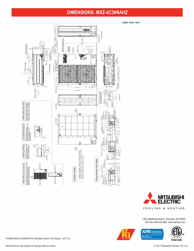
DIMENSIONS: MXZ-4C36NAHZ
Air D
ischa
rge
Rear
Air
Inta
ke
Sid
e A
ir In
take
2-12
×36 O
val h
oles
(Fou
ndati
on B
olt M
10<W
3/8>)
2-U
Shap
ed no
tched
holes
(Fou
ndati
on B
olt M
10<W
3/8>)
Install
ation F
eet
42<1
-21/
32>
56<2
-7/3
2>
370<14-9/16>
25<1>
417<16-13/32>
70<2
-3/4
>
28<1-3/32>
225
<8-2
7/32
>22
5<8
-27/
32>
330<13>
600
<23-
5/8>
19<3/4>
56<2
-7/3
2>
33.2
<1-5
/16>
0 53<2
-3/3
2>
1/2 in
ch C
ondu
itatt
achm
ent
{22
.2<7/8
>
{34
.5<1-2
3/64>
Whe
n in
stal
ling
the
cond
uit.
Set
the
atta
chm
ent t
o th
e in
ner s
ide
of e
ach
pane
l.
1 inc
h Con
duit
attac
hmen
t
Scale
1:5
24.7<31/32>
5<3/16>
60<2
-3/8
>24
<15/
16>
101.
5<4
>
Gro
und
for t
hebr
anch
box
powe
r sup
ply
For t
he
powe
r sup
ply
For t
he
bran
ch b
oxpo
wer s
uppl
y
For t
he
trans
miss
ion
line
For c
once
ntra
tion
cont
rol
Term
inal
con
nect
ion
From
left
to ri
ght
Hand
le fo
r mov
ing
Gro
und
for t
he tr
ansm
issio
n lin
eG
roun
d fo
r con
cent
ratio
n co
ntro
l
1 2Hand
le for
mov
ing
Serv
ice p
anel
Gro
und
for t
he p
ower
sup
ply
("GR"
mar
king
posit
ion)
632<24-7/8>
1338<52-11/16>
26<1-1/32>
1050
<41-
11/3
2>
1067<42>
426 <16-25/32> *1
369<14-17/32>
362
<14-
1/4>
510 <20-3/32> *1
Rear
pipi
ng co
ver
Fron
t pip
ing
cove
r
Air
inta
ke
Botto
m pip
ing ho
le(K
nock
out)
Drain
hole
(5- {
33<1
-5/1
6>)
160
<6-5
/16>
110
<4-1
1/32
>16
0<6
-5/1
6>16
0<6
-5/1
6>
136<5-11/32>
86<3-3/8>
81<3
-3/1
6>
45<1
-25/
32>
154<6-1/16>
Righ
t pipi
ng ho
le(K
nock
out)
Cond
uit ho
le( {
24<1
5/16>
Knoc
kout)
Cond
uit ho
le({3
7<1-
15/32
>Kno
ckou
t)
Righ
t tru
nkin
g ho
le(K
nock
out)
92<3
-5/8
>
60<2
-3/8
>
5<3/16>60<2-3/8>
55<2
-3/1
6>
53<2
-3/3
2>
92<3-5/8>
26<1-1/32>27<1-1/16>
29<1
-5/3
2>73<2-7/8>
{9
2<3
-5/8
>
Min
. 150
mm
<5-2
9/32
>M
in. 1
000m
m<3
9-3/
8>
Side
Air
Inta
ke
Cond
uit ho
le( {
37<1
-15/3
2>Kn
ocko
ut)Fr
ont t
runk
ing h
ole(K
nock
out)
Fron
t pipi
ng h
ole(K
nock
out)
Cond
uit ho
le({
24<1
5/16>
Knoc
kout)
55<2-3/16> 27<1-1/16>
92<3
-5/8
>
75<2
-15/
16>
73<2-7/8> 26<1-1/32>
55<2
-3/1
6>
60<2-3/8>
5<3/16>
60<2
-3/8
>
{92
<3-5
/8>
FREE
Min
. 15m
m<1
9/32
>M
in. 1
5mm
<19/
32>
Hand
le fo
rm
oving
Hand
le for
movin
g
Rear
Air
Inta
ke Cond
uit ho
le( {
24<1
5/16>
Knoc
kout)
Cond
uit ho
le( {
37<1
-15/3
2>Kn
ocko
ut)
Rear
trun
king
hole
(Kno
ckou
t)
Rear
pipi
ng h
ole(K
nock
out)
75<2
-15/
16>
60<2-3/8>
92<3
-5/8
>
73<2-7/8> 26<1-1/32>
27<1-1/16>55<2-3/16>
55<2
-3/1
6>
5<3/16>
60<2
-3/8
>
{92
<3-5
/8>
1…
…Re
frige
rant
GAS
pip
e co
nnec
tion
(FLA
RE){
15.8
8 (5
/8F)
2…
…Re
frige
rant
LIQ
UID
pipe
con
nect
ion
(FLA
RE){
9.52
(3/8
F)*1
......
.Indi
catio
n of
STO
P VA
LVE
conn
ectio
n lo
catio
n.
Pipi
ng a
nd w
iring
con
nect
ions
can
be m
ade
from
4 d
irect
ions
:FR
ON
T, R
ight
, Rea
r and
Bel
ow.
4 PIPI
NG-W
IRING
DIRE
CTION
S3 F
OUND
ATIO
N BO
LTS
2 SER
VICE
SPA
CE1 F
REE S
PACE
(Arou
nd th
e unit
)Ple
ase s
ecure
the u
nit fir
mly
with
4 fou
ndati
on (M
10<W
3/8>)
bolts
.(B
olts a
nd w
ashe
rs mu
st be
pu
rchas
ed lo
cally.
)
Dime
nsion
s of s
pace
need
edfor
servi
ce ac
cess
are
show
n in t
he be
low di
agra
m.Th
e dia
gram
belo
w sh
ows a
bas
ic ex
ample
.Ex
plant
ion o
f par
ticula
r det
ails a
regiv
en in
the
insta
llatio
n m
anua
ls et
c.
Max.<Fou
ndat
ion
bolt
heig
ht>
FOUN
DATIO
N
Servi
ce sp
ace
Min. Min.
Min.
Min.
15<1
9/32
>
500
<19-
11/1
6>
500<19-11/16>
150<5-29/32>
30<1-3/16>
Piping
Knoc
kout
Hole
Detai
ls
Exam
ple of
Note
s
mm
<inc
h>
Unit: mm <in>