Shape-memory alloys: effective 3D modelling, … alloys: effective 3D modelling, ... heads since...
25
Int. J. Computational Materials Science and Surface Engineering, Vol. X, No. Y, xxxx 1 Copyright © 200x Inderscience Enterprises Ltd. Shape-memory alloys: effective 3D modelling, computational aspects and design of devices F. Auricchio and A. Reali* Dipartimento di Meccanica Strutturale, Università degli Studi di Pavia, Via Ferrata 1, Pavia (PV), 27100, Italy E-mail: [email protected] E-mail: [email protected] *Corresponding author A. Tardugno Department of Bioengineering, Imperial College London, Royal School of Mines Building, South Kensington Campus, London, SW7 2 AZ, UK E-mail: [email protected] Abstract: The employment of shape-memory alloys (SMA) in a large number of applications in many fields of engineering, among which biomedical engineering, has been the motivation for an increasing interest in the direction of a correct and exhaustive modelling of their macroscopic behaviour in order to construct reliable simulation tools, which can be successfully used in the design procedures of SMA devices. In this paper, we review a robust three-dimensional model giving a good description of pseudo-elastic and shape-memory behaviours and we use it for the development of a new design procedure of SMA micro-actuators. Starting from a SMA micro-device proposed in the literature, we then adopt such a procedure to design a new effective variant of micro-gripper. Keywords: shape-memory alloys; SMA; 3D constitutive modelling; SMA device design; micro-actuators; micro-grippers. Reference to this paper should be made as follows: Auricchio, F., Reali, A. and Tardugno, A. (xxxx) ‘Shape-memory alloys: effective 3D modelling, computational aspects and design of devices’, Int. J. Computational Materials Science and Surface Engineering, Vol. X, No. Y, pp.000–000. Biographical notes: Ferdinando Auricchio received his Laurea (1989) in Civil Engineering at the University of Naples and his MSc (1991) and PhD (1995) at the University of California at Berkeley. Since 1994, he worked as an Assistant Professor of Mechanics of Solids at the University of Rome Tor Vergata, and as an Associate Professor (since 1998) and Full Professor (since 2001) of Mechanics of Solids at the Department of Structural Mechanics (which he heads since 2003), University of Pavia. His main research interests are advanced material constitutive modelling, mixed and extended finite elements, isogeometric analysis, biomechanics and numerical techniques for fast dynamics.
Transcript of Shape-memory alloys: effective 3D modelling, … alloys: effective 3D modelling, ... heads since...

Int. J. Computational Materials Science and Surface Engineering, Vol. X, No. Y, xxxx 1
Copyright © 200x Inderscience Enterprises Ltd.
Shape-memory alloys: effective 3D modelling, computational aspects and design of devices
F. Auricchio and A. Reali* Dipartimento di Meccanica Strutturale, Università degli Studi di Pavia, Via Ferrata 1, Pavia (PV), 27100, Italy E-mail: [email protected] E-mail: [email protected] *Corresponding author
A. Tardugno Department of Bioengineering, Imperial College London, Royal School of Mines Building, South Kensington Campus, London, SW7 2 AZ, UK E-mail: [email protected]
Abstract: The employment of shape-memory alloys (SMA) in a large number of applications in many fields of engineering, among which biomedical engineering, has been the motivation for an increasing interest in the direction of a correct and exhaustive modelling of their macroscopic behaviour in order to construct reliable simulation tools, which can be successfully used in the design procedures of SMA devices. In this paper, we review a robust three-dimensional model giving a good description of pseudo-elastic and shape-memory behaviours and we use it for the development of a new design procedure of SMA micro-actuators. Starting from a SMA micro-device proposed in the literature, we then adopt such a procedure to design a new effective variant of micro-gripper.
Keywords: shape-memory alloys; SMA; 3D constitutive modelling; SMA device design; micro-actuators; micro-grippers.
Reference to this paper should be made as follows: Auricchio, F., Reali, A. and Tardugno, A. (xxxx) ‘Shape-memory alloys: effective 3D modelling, computational aspects and design of devices’, Int. J. Computational Materials Science and Surface Engineering, Vol. X, No. Y, pp.000–000.
Biographical notes: Ferdinando Auricchio received his Laurea (1989) in Civil Engineering at the University of Naples and his MSc (1991) and PhD (1995) at the University of California at Berkeley. Since 1994, he worked as an Assistant Professor of Mechanics of Solids at the University of Rome Tor Vergata, and as an Associate Professor (since 1998) and Full Professor (since 2001) of Mechanics of Solids at the Department of Structural Mechanics (which he heads since 2003), University of Pavia. His main research interests are advanced material constitutive modelling, mixed and extended finite elements, isogeometric analysis, biomechanics and numerical techniques for fast dynamics.

2 F. Auricchio et al.
Alessandro Reali received his Laurea (2001) in Civil Engineering at the University of Pavia and his MSc (2004) and PhD (2005) in Earthquake Engineering at the ROSE School (IUSS and University of Pavia). Since 2005, he worked as a Post-doctoral Fellow at the Department of Structural Mechanics, University of Pavia, where he is currently Assistant Professor of Mechanics of Solids (since 2008). His main research interests are isogemetric analysis, advanced material constitutive modelling, mixed finite elements and numerical techniques for fast dynamics.
Angelo Tardugno received his Bachelor (2004) in Biomedical Engineering at the University of Pavia and his Master (2006) in Biomechanics at the same university. He is currently a PhD student at Imperial College London in the Department of Bioengineering, where he is working on models describing the relationships between bone morphology and its mechanical properties.
1 Introduction
The great and always increasing interest in shape-memory alloys (SMA) (cf., Duerig et al., 1990; Duerig and Pelton, 2003) and their industrial applications in many branches of engineering is deeply stimulating the research on constitutive laws. As a consequence, many models are able to reproduce one or both of the well-known SMA macroscopic behaviours, referred to as pseudo-elasticity and shape-memory effect, have been proposed in the literature in the last years [refer for instance to Bouvet et al. (2004), Govindjee and Miehe (2001), Helm and Haupt (2003), Lagoudas and Entchev (2004), Leclercq and Lexcellent (1996), Levitas (1998), Levitas and Preston (2002a, 2002b), Peultier et al. (2004) and Raniecki and Lexcellent (1994)].
In particular, the constitutive law proposed by Souza et al. (1998) and improved by Auricchio and Petrini (2004a) [and later also by Auricchio and Reali (2007) and Auricchio et al. (2007, 2009)] seems to be attractive. Developed within the theory of irreversible thermodynamics, this model is in fact able to describe both pseudo-elasticity and shape-memory effect and the corresponding solution algorithm is simple and robust as it is based on a plasticity-like return map procedure.
The robustness of such a model makes it particularly suitable for implementation within finite element codes, allowing in this way the simulation of the behaviour of complex SMA devices. In this paper, we take advantage of this model to study SMA micro-actuators and to develop for such devices an effective design technique relying on the complete SMA hysteresis and not only on their elastic properties as it is done in the classical approach. In particular, we study the behaviour of a micro-gripper proposed in the literature (Kohl, 2002) and we then propose and design an alternative and promising variant.
2 3D SMA Phenomenological model
In this first part of the paper, we present and discuss in detail the 3D phenomenological model for SMA introduced by Auricchio and Petrini (2004a, 2004b) and Souza et al. (1998) within the context of thermo-electro-mechanical coupling.

Shape-memory alloys 3
2.1 Time-continuous frame
The model assumes the total strain ε and the absolute temperature T as control variables, the transformation strain etr as internal one. The second-order tensor etr describes the strain associated to the transformation between the two solid phases referred to as martensite and austenite. Here, this quantity has a fully reversible evolution and can be completely recovered when unloading to a zero stress state. Moreover, we require that
,trLε≤e (1)
where ⋅ is the usual Euclidean norm and εL is a material parameter corresponding to the maximum transformation strain reached at the end of the transformation during an uniaxial test.
Assuming a small strain regime, justified by the fact that the approximation of large displacements and small strains is valid for several applications, the following standard additive decomposition can be considered
1 ,3θε = + e
where θ = tr(ε) and e are respectively the volumetric and the deviatoric part of the total strain ε, while 1 is the second-order identity tensor. The free energy density function Ψ for a polycrystalline SMA material is then expressed as the convex potential
220
20 0
00
1( , , , ) 3 ( )2
1 ( )2
log ( ),L
tr tr
tr trf
tr
T K G K T T
T M h u T
Tc T T TT ε
θ θ α θ
β η
= + − − −
+ − + + −
⎡ ⎤⎛ ⎞+ − − +⎢ ⎥⎜ ⎟
⎢ ⎥⎝ ⎠⎣ ⎦
e e e e
e e
e
Ψ
I
(2)
where K and G are respectively the bulk and the shear modulus, α is the thermal expansion coefficient, β is a material parameter related to the dependence of the critical stress on the temperature, Mf is the temperature below which only martensite phase is stable, h defines the hardening of the phase transformation, c is the heat capacity, and u0, η0 and T0 are, respectively, the internal energy, the entropy and the temperature at the reference state. Moreover, we make use of the indicator function
0 if ( )
otherwise,L
trLtr
εε⎧ ≤⎪= ⎨
+∞⎪⎩
eeI
in order to satisfy the transformation strain constraint (1); we also introduce the positive part function ,⋅ defined as
{ if 00 otherwise.a aa >=

4 F. Auricchio et al.
We remark that, since we use only a single internal variable second-order tensor to describe phase transformations, at most it is possible to distinguish between a generic parent phase (not associated to any macroscopic strain) and a generic product phase (associated to a macroscopic strain). Accordingly, the model does not distinguish between the austenite and the twinned martensite, as both these phases do not produce macroscopic strain.
We furthermore highlight that, for the sake of simplicity, the present model does not reflect the differences existing between the austenite and the martensite elastic properties.
Starting from the free energy function Ψ and following standard arguments, we can derive the constitutive equations
0
0
0
[ 3 ( )],
2 ( ),
3
log ,
,
tr
ftr
f
tr trtr
ftr tr tr
p K T T
G
T MK
T T M
TcT
T M h
θ αθ
η η α θ β
β
⎧⎪ ∂⎪ = = − −⎪ ∂⎪ ∂⎪ = = −
∂⎪⎪ −∂⎪ = − = + −⎨
∂ −⎪⎪
⎛ ⎞⎪ + ⎜ ⎟⎪ ⎝ ⎠⎪⎪ ∂
= − = − − − −⎪∂⎪⎩
s e ee
e
e eX s ee e e
Ψ
Ψ
Ψ
Ψγ
(3)
where p = tr(σ)/3 and s are respectively the volumetric and the deviatoric part of the stress σ, X is a thermodynamic stress-like quantity associated to the transformation strain etr, and η is the entropy. The variable γ results from the indicator function subdifferential
( )L
trε∂ eI and it is defined as
0 ,
0 ,
trL
trL
if
if
ε
ε
⎧ = <⎪⎨
≥ =⎪⎩
e
e
γ
γ
so that ( ) / .L
tr tr trε∂ =e e eI γ
To describe phase transformation and inelasticity evolution, we choose a limit function F defined as
( )F R= −X X (4)
where R is the radius of the elastic domain in the deviatoric space. Considering an associative framework, the flow rule for the internal variable takes the
form
.tr Fζ ζ∂= =
∂Xe
X X& && (5)

Shape-memory alloys 5
The model is then completed by the classical Kuhn-Tucker conditions
0,0,0.
FF
ζ
ζ
⎧ ≥⎪ ≤⎨⎪ =⎩
&
& (6)
Following classical arguments Lemaitre and Chaboche (1990), we can also compute the evolution of the current internal energy u, using the first principle of thermodynamics, as
: ,u T T rη η ε= + + = + −∇ ⋅q& & && &Ψ σ (7)
being r and q, respectively, the heat source and flux vector. Moreover, since SMA actuators are often electrically activated by Joule effect, we
extend the model to take into consideration also thermo-electro-mechanical coupling. Limiting the discussion to the steady-state, we recall that the electrical problem in an isotropic conductive material with an applied stationary potential difference is described by the following equations
0, ,
,el
V
σ
∇⋅ == −∇
=
jE
j E
(8)
with j the current density, E the electric field, V the electric potential, σel the electric conductivity constant. Accordingly, between electrical and thermal fields, a coupling takes place through the Joule effect, i.e., when a current density j passes through a conductive body unit volume, the electric field E generates a power density in form of a heat production
.elcH = ⋅E j (9)
Hence, under our hypotheses of small deformations, no internal heat source (r = 0), and isotropic Fourier law (q = −Kth∇T, with Kth thermal conductivity constant), we can write the thermo-electro-mechanical coupled problem using the free energy definition (2) into equation (7), thus obtaining
2 .thchcT K T w′− ∇ =& (10)
We highlight that in the above equation chw′ is the volume heat source, which is defined as
,ch elc mech tmcw H D H′ = + + (11)
where Helc is the heat production due to thermo-electrical coupling defined by (9), Dmech is the heat production due to mechanical dissipation
: ,trmech trD ε θ
θ∂ ∂ ∂⎛ ⎞= − + +⎜ ⎟∂ ∂ ∂⎝ ⎠
e ee e
&&& &Ψ Ψ Ψσ (12)
and Htmc is the heat production due to thermo-mechanical coupling (thermo-elastic effect and phase transformation latent heat)

6 F. Auricchio et al.
2 2 2,tr
tmc trH TT T T
θθ
⎛ ⎞∂ ∂ ∂= + +⎜ ⎟⎜ ⎟∂ ∂ ∂ ∂ ∂ ∂⎝ ⎠
e ee e
&& &Ψ Ψ Ψ (13)
We finally remark that for this model we have
: ,
: 3 .
trmech
trtr
tmc tr
D
H T Kβ αθ
=
⎛ ⎞⎜ ⎟= −⎜ ⎟⎝ ⎠
X e
e ee
&
& & (14)
Observation 1: The proposed model is thermodynamically consistent since it satisfies the second principle of thermodynamics in the form of the Clausis-Duhem inequality [for more details see Auricchio and Petrini (2004a)].
Observation 2: By exploiting basic convex analysis tools [see, e.g., Clarke (1990)] we can rewrite our constitutive model (3)–(6) in the equivalent form
0.
tr tr
p
T
D
θ
η
−⎛ ⎞ ⎛ ⎞⎜ ⎟ ⎜ ⎟−⎜ ⎟ ⎜ ⎟+ ∂ ∋⎜ ⎟ ⎜ ⎟⎜ ⎟ ⎜ ⎟⎜ ⎟ ⎜ ⎟∂⎝ ⎠ ⎝ ⎠
s e
e e&
Ψ (15)
Here ∂D stands for the subdifferential of the function D defined as
{ }( ) 0
( ) sup : ,tr tr
FD
≤=
Ae A e (16)
which is the dissipation function associated to the phase transformation mechanism. It can be shown that D(etr) = R||etr||, as well as that it is the Fenchel-Legendre conjugate of the indicator function of the non-empty, convex and closed-domain
{ : ( ) 0}.F= ≤A AE
Hence, it is easy to check that D is positively 1-homogeneous, that is
( ) ( ) 0.tr trD D= ∀ >e eλ λ λ
Namely, the time-evolution of etr is of rate-independent type since we readily have that
( ) ( ) 0.tr trD D∂ = ∂ ∀ >e eλ λ
The formulation of rate-independent evolution problems in terms of a doubly-non-linear differential inclusion as in (15) has recently attracted a good deal of attention. In particular, the mathematical treatment of relations as (15) is nowadays fairly settled and existence, uniqueness and time-discretisation results are available. The interested reader is referred to the recent survey (Mielke, 2005) where a comprehensive collection of mathematical results on doubly-non-linear rate-independent problems is provided.

Shape-memory alloys 7
2.2 Time-discrete frame
Let us now focus on the crucial issue of computing the stress and internal variable evolution of a SMA sample in a strain-driven situation. We shall directly concentrate ourselves on the solution of the time-incremental problem. Namely, we discretise the time-interval of interest [0, tf] by means of the partition I = {0 = t0 < t1 < … < tN −1 < tn = tf}, assume to be given the state of the system (pn, sn, ηn, tr
ne ) at time tn, the actual total strain (θ, e) and temperature T at time tn + 1 (note that for notation simplicity here and in the following we drop the subindex n + 1 for all the variables computed at time tn + 1), and solve for (p, s, η, etr). For the sake of numerical convenience, instead of solving (3) we prefer to perform some regularisation. Indeed, we let ⋅ be defined as
2 ,δ δ= + −a a
(δ is a user-defined parameter controlling the smoothness of the norm regularisation) and introduce the regularised free energy density Ψ as
220
20 0
00
1( , , , ) 3 ( )2
1 ( )2
log ( ).L
tr tr
tr trf
tr
T K G K T T
T M h u T
Tc T T TT
η
ε
θ θ α θ
β
= + − − −
+ − + + −
⎡ ⎤⎛ ⎞+ − − +⎢ ⎥⎜ ⎟
⎢ ⎥⎝ ⎠⎣ ⎦
e e e e
e e
e
Ψ
I
(17)
Finally, the updated values (p, s, η, etr) for regularised constitutive model can be computed from the following relations
0
00
2
[ 3 ( )],
2 ( ),
3 _ log ,
,
,
,
tr
ftr
f
tr trtr
f trtr
tr trn
p K T T
G
T M TK cTT M
T M h
F R
θ α
η η α θ β
βδ
ζ
= − −⎧⎪
= −⎪⎪ − ⎛ ⎞⎪ = + − ⎜ ⎟⎪ − ⎝ ⎠⎪⎪⎨ = − − − −⎪⎪ +⎪⎪
= + Δ⎪⎪⎪ = −⎩
s e e
e
e eX s eee
Xe eX
X
γ (18)
along with the requirements
0,
,
0, 0, 0,
trL
F F
ε
ζ ζ
≥⎧⎪
≤⎨⎪Δ ≥ ≤ Δ =⎩
e
γ
(19)

8 F. Auricchio et al.
where 1
dn
n
tn
ttζ ζ ζ ζ
+Δ = − ∫ & is the time-integrated consistency parameter.
We shall clearly state that our numerical experiments are not performed on the model of Section 2.1 but rather on the above-introduced δ-regularised version. This choice turns out to be quite convenient from the numerical viewpoint and preserves most of the characteristic features of the model. Moreover, it can be proved that the δ-regularised model converges to the original one as the regularisation parameter δ goes to 0. This fact along with additional mathematical analysis of the model is addressed in Auricchio et al. (2008).
2.3 Solution algorithm
The solution of the discrete model is performed by means of an elastic-predictor inelastic-corrector return map procedure as in classical plasticity problems (cf., Simo and Hughes, 1998). An elastic trial state is evaluated keeping frozen the internal variables, then a trial value of the limit function is computed to verify the admissibility of the trial state. If this is not verified, the step is inelastic and the evolution equations have to be integrated.
We remark that we distinguish two inelastic phases in our model: a non-saturated phase ( ), 0tr
Lε< =e γ and a saturated one ( ), 0 .trLε< ≥e γ In our solution
procedure we start assuming to be in a non-saturated phase, and when convergence is attained we check if our assumption is violated. If the non-saturated solution is not admissible, we search for a new solution considering saturated conditions.
For each inelastic step, we have to solve the non-linear system constituted by equation (18). Then, also the equations related to electrical and thermal fields have to be solved taking into account thermo-electro-mechanical coupling. However, as the aim of this part of the paper is just to introduce the model that we will use for our subsequent developments, without focusing on algorithmic problems, we do not describe here the algorithm that we implemented in FEAP (Taylor, 2001) to find a solution to such non-linear system. We just say that we used a staggered formulation where we consider a mechanical, an electrical and a thermal partition, and we refer interested readers to Auricchio and Petrini (2004b) for more details.
Observation 3: In the same spirit of Observation 2, we shall now recast the aforementioned algorithm (18)–(19) in terms of dissipation. Exactly as above, we assume to be given the current state of the system (pn, sn, ηn, tr
ne ) at time tn and the actual total strain (θ, e) and temperature T at time tn + 1. Then, relations (18)–(19) are nothing but the Euler-Lagrange relations for the following minimum problem
( ) ( ){ }min , , ,tr
tr tr trnD θ η
∗∗ ∗− +
ee e e eΨ (20)
along with positions (18)1 – (18)4. The minimum problem (20) corresponds in this setting to the Euler method where,
nevertheless, the usual incremental quotients are replaced by the weaker distance
( ).tr trnD ∗ −e e

Shape-memory alloys 9
Following Mielke (2005) and Auricchio et al. (2008), it can be shown that problem (20) is uniquely solvable and that the incremental solutions arising from the step-by-step solution of the minimisation problem converge to a time-continuous solution of the constitutive relation as the diameter of the time partition I goes to zero. Moreover, the model is stable with respect to the regularisation parameter δ > 0. In particular, solutions to the incremental problem (20) converge to the unique minimiser of problem
( ) ( ){ }min , , , ,tr
tr tr trnD θ η
∗∗ ∗− +
ee e e eΨ (21)
as δ goes to zero.
2.4 Numerical tests on the model
To show the model capability of reproducing the macroscopic behaviour of SMA materials, we perform a couple of proportional tension-compression stress-driven (temperature-parameterised) numerical experiments. For a complete testing of the model we refer to Auricchio and Petrini (2004a, 2004b). We consider the material properties specified in Table 1, describing the SMA that we will use in the second part of the paper and corresponding to an idealised Cu-based SMA; E and ν are respectively the Young’s modulus and the Poisson’s ratio, while all the other material constants have already been introduced previously. Table 1 Material parameters for the numerical tests
Parameter Value Unit E 53⋅103 MPa
v 0.3 -
β 2.1 MPa K–1
Mf 293 K h 1000 MPa R 20 MPa εL 4 %
δ 10–8 -
In the first experiment, we test the pseudo-elastic effect, i.e., we perform a tension-compression uniaxial test at a constant temperature T = 313 K > Mf. As it is possible to see in Figure 1, the pseudo-elastic effect is perfectly reproduced and a complete strain recovery is obtained as the stress is driven to zero.
The second experiment aims at reproducing the shape-memory effect and consists of a tension-compression uniaxial test performed at a temperature T = Mf. The result is reported in Figure 2, where it is shown that at the end of the loading cycle a residual strain is obtained. Such residual strain is however completely recovered heating the material (here we heat it up to T = 313 K).

10 F. Auricchio et al.
Figure 1 Pseudo-elastic effect (see online version for colours)
Notes: σ11 – ∈11 response to a tension-compression cycle at T = 313 K > Mf.
Black solid line: Δσ = 0.1 MPa; blue dots: Δσ = 10 MPa.
Figure 2 Shape-memory effect (see online version for colours)
Notes: σ11 – ∈11 response to a tension-compression cycle at T = Mf, followed by heating
strain recovery up to T = 313 K (ΔT = 1 K). Black solid line: Δσ = 0.1 MPa; blue dots: Δσ = 10 MPa.

Shape-memory alloys 11
We finally highlight that we performed both our tests choosing different stress-increments in order to prove the robustness of the algorithm. In particular, we used 0.1 MPa and 10 Mpa increments, which are represented on the figures using solid lines and dots, respectively. Since dots always lie on solid lines, the robustness of the algorithm is evident.
3 Micro-gripper design and analysis
In this second part of the paper, we develop a method for designing a micro-gripper able to take full advantage of SMA peculiar features and we use it to design some variants of a micro-device, whose geometry has been already proposed in the literature by Kohl (2002). To perform the numerical simulations necessary to design the device, we rely on the good performance of the model we have introduced in the previous sections to describe SMA main behaviours. Since such a model does not take into account the change in the Young’s modulus which occurs during SMA phase transformations, we have developed a method for designing the device slightly different from the classical approach, which is, quite surprisingly, completely based on the Young’s modulus difference between austenite and martensite.
3.1 Design strategy and study of a monolithic micro-gripper
First of all, we briefly illustrate the classical approach mentioned above focusing on the design of a very simple antagonist mechanism made of two springs, as shown in Figure 3.
Figure 3 A simple antagonist mechanism (see online version for colours)

12 F. Auricchio et al.
The lower spring is deformed by applying a force to one of its ends, then both the ends of the series system are constrained. Now we are ready to activate the system by heating each of the two springs alternatively. In order to determine the pre-deformation to be reached in the lower spring, we can create an overall representation of the system. This can be done firstly by characterising both of the springs in a force-displacement plane and then by superimposing the characteristics of the upper spring on those of the lower spring. Since there are two possible conditions (i.e., the martensitic and austenitic condition) for each of the springs, we need two different characterisation for each of them.
In Kohl (2002), the material is supposed always working in its elastic range and the overall representation would look, therefore, as in Figure 4.
As we can see, there are four different equilibrium points. Nevertheless, we are interested only in two of them, i.e., the intersection between the lower spring in its austenitic condition and the upper spring in its martensitic condition and vice versa.
Figure 4 Equilibrium points for two antagonistic springs, considering only their elastic range (see online version for colours)
We now choose not to rely on the Young’s modulus difference between the austenite and the martensite; so, in our developments we neglect such a difference. Under this hypothesis, following the classical approach discussed above, we would never be able to obtain a working device, unless we decide to consider also the inelastic range of the two springs. If we consider the hysteresis of the spring characteristic, we would be able to obtain two different equilibrium points, one for the closed condition and another for the open condition. According to these considerations, we can represent the overall device as shown in Figure 5.

Shape-memory alloys 13
Figure 5 Equilibrium points for two antagonistic springs, considering their hysteresis (see online version for colours)
Defined how to proceed, we can now face the problem of designing a micro-gripper. The shape of the overall device (cf., Kohl, 2002) is shown in Figure 6, where we report its geometrical properties on one of the meshes we created for the simulations in FEAP. We remark that, for all the numerical studies we propose in the following, we have used the constitutive model described in the first part of the paper.
Figure 6 Shape and size of the micro-gripper
14 F. Auricchio et al.
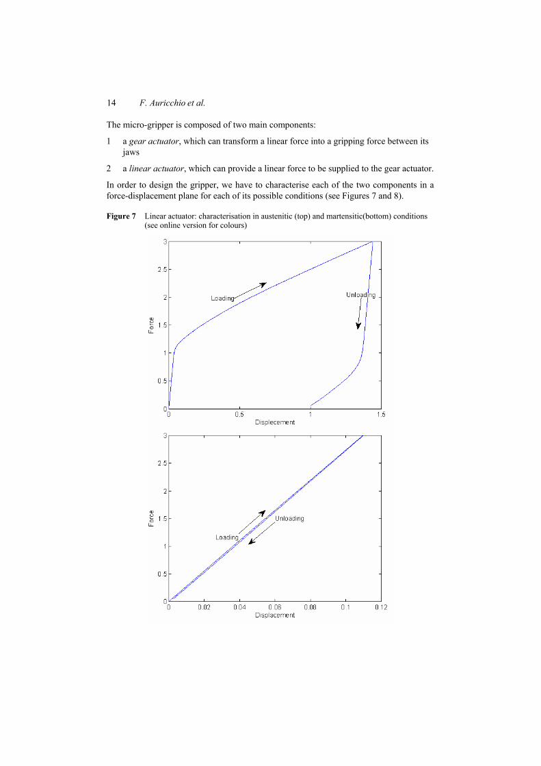
The micro-gripper is composed of two main components:
1 a gear actuator, which can transform a linear force into a gripping force between its jaws
2 a linear actuator, which can provide a linear force to be supplied to the gear actuator.
In order to design the gripper, we have to characterise each of the two components in a force-displacement plane for each of its possible conditions (see Figures 7 and 8).
Figure 7 Linear actuator: characterisation in austenitic (top) and martensitic(bottom) conditions (see online version for colours)

Shape-memory alloys 15
Figure 8 Gear actuator: characterisation in austenitic (top) and martensitic (bottom) conditions (see online version for colours)
Once created the four characteristics, we can obtain an overall representation of the whole device by superimposing the characteristics of the gear actuator on those of the linear actuator, thus obtaining the graphic in Figure 9.
We have considered only the unloading branch of the characteristics of the two actuators in their austenitic condition, whereas for the actuators in their martensitic condition we have considered only the loading part.

16 F. Auricchio et al.
As it is shown in Figure 9, there are only two interesting equilibrium points: the intersections between the characteristic of the actuators in their austenitic phase with the characteristics of the other actuator in its martensitic phase. The position of the equilibrium points change accordingly to the pre-deformation of the linear actuator, as it is shown in Figure 10.
Figure 9 Equilibrium points for the two micro-actuators (see online version for colours)
Figure 10 Equilibrium points for the two micro-actuators for two different pre-deformations (see online version for colours)

Shape-memory alloys 17
According to the chosen pre-deformation, we would have different forces corresponding to the two equilibrium points. The force corresponding to the close equilibrium point determines how much the jaws of the gear actuator will close. We therefore choose the pre-deformation to be used according to the degree of closure we wish to obtain.
Given the two pre-deformations in Figure 10, we can test the behaviour of the gear actuator as the force at the equilibrium point changes. As we can see, the second pre-deformation allows for a greater closing condition and it is therefore better than the first one.
Besides the design of devices using the procedure so far addressed, due to the flexibility of the finite element method, we can also model and study the whole device. We then simulate the behaviour of the micro-gripper, obtaining the results shown in Figure 11: we have an actual movement of the gripper to the equilibrium points we have found during the design of the device. Moreover, the two actuators are always activated independently and they are never in the austenitic condition at the same time.
Figure 11 Results of the simulation of a monolithic micro-gripper (see online version for colours)
3.2 Study of a non-monolithic micro-gripper
Now that we have proven the effectiveness of our designing method, we can use it to design a different type of micro-gripper which is composed of two components, one showing the shape-memory effect and the other showing pseudo-elasticity. We decided to replace the gear actuator with a pseudo-elastic component with the same shape and size. We propose to heat the linear actuator using a thermoelectric component known as Peltier device, which can be used both for heating and cooling.
As we have done in the previous case, we start by characterising the two components in a force-displacement plane, obtaining three different characteristics (Figures 12 and 13).

18 F. Auricchio et al.
Figure 12 Linear actuator: characterisation in martensitic (top) and austenitic (bottom) conditions (see online version for colours)

Shape-memory alloys 19
Figure 13 Pseudo-elastic component: characterisation in austenitic condition (see online version for colours)
We then build an overall representation of the device by superimposing all the characteristics on the same plane (Figure 14). We can find four different intersection points but, as we have done for the previous case, we focus only on two of them. Once we have chosen the pre-deformation to be used, we can simulate the device, obtaining the results reported in Figure 15, where it is possible to see that the gripper actually moves towards the two equilibrium points we have found during the designing of the device.
Figure 14 Equilibrium points for the two micro-actuators (see online version for colours)

20 F. Auricchio et al.
Figure 15 Results of the simulation of a non-monolithic micro-gripper (see online version for colours)
Since we are using a Peltier device to heat and cool off the linear actuator, we can control the temperature the actuator itself would reach. Thus, we can think of a gripper which has more than one closing condition, in fact the temperature of the linear actuator determines how much the gripper jaws would close: the higher the temperature of the actuator, the more the jaws will close. We focus on the creation of a gripper with two closing positions; the extension to the case of multi-closing conditions is then straightforward.
First of all, we characterise the behaviour of the two components of the gripper in a force-displacement plane. Since the linear actuator would work at three different temperatures (i.e., under the temperature threshold, slightly above the threshold and largely above the threshold) we need three different characterisations of this component. As for the upper component, we only need one characterisation, since it is always in its austenitic condition (Figures 16 and 17).
We are now able to provide an overall representation of the device (Figure 18). After we have applied the pre-deformation to the linear actuator, the equilibrium point would be AP. We then heat the linear actuator to an intermediate temperature, so that its characteristic would move from the dotted to the dashed one: the new equilibrium point would be C1. If we heat the linear actuator to a higher temperature, its characteristic would change from the dashed to the continuous one, and the new equilibrium point would be C2. If we now cool down the linear actuator again to the intermediate temperature, there would be no change in the equilibrium point: in fact, the equilibrium point C2 would fall onto the hysteresis of the characteristic at the intermediate temperature and it would therefore be an equilibrium point also for that temperature. Only if we cool the device to room temperature, the gripper would open again and the equilibrium point would be A. We can simulate this behaviour and the results are those provided in Figure 19. As it is shown, we actually find the behaviour we have forecast during the designing of the device: we can actually close partially the device and then

Shape-memory alloys 21
close it completely but we cannot achieve a partial reopening of the device once we have closed it completely.
Figure 16 Linear actuator: characterisation in martensitic condition (top) and at an intermediate temperature (bottom) (see online version for colours)

22 F. Auricchio et al.
Figure 17 Linear actuator: characterisation in austenitic condition (top); pseudo-elastic component: characterisation in austenitic condition (bottom) (see online version for colours)

Shape-memory alloys 23
Figure 18 Equilibrium points for the two components (see online version for colours)
Figure 19 Results of the simulation of a non-monolithic micro-gripper with two closing conditions (see online version for colours)
4 Conclusions
In the present paper, an effective 3D constitutive model for describing the macroscopic behaviour of SMA within a thermo-electro-mechanical framework has been described (see Auricchio and Petrini, 2004a, 2004b; Souza et al., 1998). Such a model has been then employed in order to study design and simulate SMA micro-devices. In fact, using

24 F. Auricchio et al.
such a model implemented within FEAP, in the second part of the paper, we have developed a new approach to the design of micro-grippers based on their inelastic behaviour. This method has proven to be efficient and we have used it to design both a monolithic and a non-monolithic version of a micro-gripper. We have then exploited the thermal properties of SMA to develop a further version of the device which enables for two different closing conditions. A fundamental future development is the realisation of the device in order to test its real behaviour.
Acknowledgements
The authors would like to thank Prof. Manfred Kohl (University of Karlsruhe), Dr. Lorenza Petrini (Politecnico di Milano) and Dr. Ulisse Stefanelli (IMATI-CNR, Pavia) for the fruitful discussions on the subject of the present paper.
This work has been partially supported by Regione Lombardia through the INGENIO research program Laser processing of SMA micro-devices; by the Ministero dell’Istruzione, dell’Università e della Ricerca (MIUR) through the PRIN research program Shape memory alloy active microactuators and devices for biomedical applications: constitutive modelling, structural analysis, design, use of laser techniques for prototype implementation and experimental validation; by the European Science Foundation through the EUROCORES S3T project SMARTeR: Shape memory alloys to regulate transient responses in civil engineering; and by the European Research Council through the Starting independent research grant BioSMA: mathematics for shape memory technologies in biomechanics.
References Auricchio, F. and Petrini, L. (2004a) ‘A three-dimensional model describing stress-temperature
induced solid phase transformations. Part I: solution algorithm and boundary value problems’, International Journal for Numerical Methods in Engineering, Vol. 61, pp.807–836.
Auricchio, F. and Petrini, L. (2004b) ‘A three-dimensional model describing stress-temperature induced solid phase transformations. Part II: thermomechanical coupling and hybrid composite applications’, International Journal for Numerical Methods in Engineering, Vol. 61, pp.716–737.
Auricchio, F. and Reali, A. (2007) ‘A phenomenological one-dimensional model describing stress-induced solid phase transformation with permanent inelasticity’, Mechanics of Advanced Materials and Structures, Vol. 14, pp.43–55.
Auricchio, F., Mielke, A. and Stefanelli, U. (2008) ‘A rate-independent model for the isothermal quasi-static evolution of shape memory materials’, Mathematical Models and Methods in Applied Sciences, Vol. 18, pp.125–164.
Auricchio, F., Reali, A. and Stefanelli, U. (2007) ‘A three-dimensional model describing stress-induced solid phase transformation with permanent inelasticity’, International Journal of Plasticity, Vol. 23, pp.207–226.
Auricchio, F., Reali, A. and Stefanelli, U. (2009) ‘A macroscopic 1D model for shape memory alloys including asymmetric behaviors and transformation-dependent elastic properties’, Computer Methods in Applied Mechanics and Engineering, Vol. 198, pp.1631–1637.
Bouvet, C., Calloch, S. and Lexcellent, C. (2004) ‘A phenomenological model for pseudoelasticity of shape memory alloys under multiaxial proportional and nonproportional loadings’, European Journal of Mechanics A/Solids, Vol. 23, pp.37–61.

Shape-memory alloys 25
Clarke, F.H. (1990) Optimization and Nonsmooth Analysis, 2nd ed., Classics in Applied Mathematics, 5, Society for Industrial and Applied Mathematics (SIAM), Philadelphia, PA.
Duerig, T. and Pelton, A. (Eds.) (2003) SMST-2003 Proceedings of the International Conference on Shape Memory and Superelastic Technology Conference, ASM International.
Duerig, T.W., Melton, K.N., Stoekel, D. and Wayman, C.M. (1990) Engineering Aspects of Shape Memory Alloys, Butterworth-Heinemann, London.
Govindjee, S. and Miehe, C. (2001) ‘A multi-variant martensitic phase transformation model: formulation and numerical implementation’, Computer Methods in Applied Mechanics and Engineering, Vol. 191, pp.215–238.
Helm, D. and Haupt, P. (2003) ‘Shape memory behaviour: modelling within continuum thermomechanics’, International Journal of Solids and Structures, Vol. 40, pp.827–849.
Kohl, M. (2002) Shape Memory Microactuators, Springer. Lagoudas, D.C. and Entchev, P. (2004) ‘Modeling of transformation-induced plasticity and its
effect on the behavior of porous shape memory alloys. Part I: constitutive model for fully dense SMAs’, Mechanics of Materials, Vol. 36, pp.865–892.
Leclercq, S. and Lexcellent, C. (1996) ‘A general macroscopic description of the thermomechanical behavior of shape memory alloys’, Journal of Mechanics and Physics of Solids, Vol. 44, pp.953–980.
Lemaitre, J. and Chaboche, J.L. (1990) Mechanics of Solid Materials, Cambridge University Press. Levitas, V.I. (1998) ‘Thermomechanical theory of martensitic phase transformations in inelastic
materials’, International Journal of Solids and Structures, Vol. 35, pp.889–940. Levitas, V.I. and Preston, D.L. (2002a) ‘Three-dimensional Landau theory for multivariant
stress-induced martensitic phase transformations. I. Austenite↔martensite’, Physical Review B, Vol. 66, pp.134206:1–9.
Levitas, V.I. and Preston, D.L. (2002b) ‘Three-dimensional Landau theory for multivariant stress-induced martensitic phase transformations. II. Multivariant phase transformations and stress space analysis’, Physical Review B, Vol. 66, pp.134207:1–15.
Mielke, A. (2005) ‘Evolution of rate-independent systems’, in Dafermos, C. and Feireisl, E. (Eds.): Handbook of Differential Equations, Elsevier.
Peultier, B., Benzineb, T. and Patoor, E. (2004) ‘Modelling of the martensitic phase transformation for finite element computation’, Journal de Physique IV, Vol. 115, pp.351–359, France.
Raniecki, B. and Lexcellent, C. (1994) ‘RL models of pseudoelasticity and their specification for some shape-memory solids’, European Journal of Mechanics, A: Solids, Vol. 13, pp.21–50.
Simo, J.C. and Hughes, T.J.R. (1998) Computational Inelasticity, Springer-Verlag, New York. Souza, A.C., Mamiya, E.N. and Zouain, N. (1998) ‘Three-dimensional model for solids undergoing
stress-induced phase transformations’, European Journal of Mechanics, A: Solids, Vol. 17, pp.789–806.
Taylor, R.L. (2001) FEAP: A Finite Element Analysis Program, programmer manual, available at http://www.ce.berkeley.edu/~rlt/feap/.