Safe maintenance of hydraulic systems · PDF fileAuthor: Berufsgenossenschaftlicher...
96
BG-Information Safe maintenance of hydraulic systems English Translation of the German BGI 5100 from 04/2007 BGI 5100 e April 2008 i
Transcript of Safe maintenance of hydraulic systems · PDF fileAuthor: Berufsgenossenschaftlicher...
Deutsche Gesetzliche Unfallversicherung e.V. (DGUV)
Mittelstraße 5110117 BerlinTel.: 030 288763-800Fax : 030 288763-808
Committee of experts “Mechanical engineering, manufacturingsystems, steel construction” Fachausschuss Maschinenbau, Fertigungssysteme, Stahlbau (FA MFS)
BG-Information
Safe maintenance of hydraulic systems
English Translation of the German BGI 5100 from 04/2007
Luxemburger Straße 449, 50939 KölnTelefon: (02631) 8012222Telefax: (02631) 8012223E-Mail: [email protected] BGI 5100 e April 2008
iNote:
Regarding deactivated accident prevention regulations, especially of the so-called machine old stock, as well as older directives, safety regulations, anddata sheets that have to be used on a continuous basis under their previousZH 1 number, see internet versions of the DGUV
„http://www.dguv.de“.
BGI 5100:BGI 5100e 11.08.2008 13:04 Seite 2
Disclaimer and notice
The “Deutsche Gesetzliche Unfallversicherung” (DGUV) and the Fachausschuss Maschi-nenbau Fertigungssysteme Stahlbau (FA MFS) and the translator make no express or implied warranty with regard to the safe maintenance procedures and rules or efficiency for any particular purpose. The safe maintenance procedures and rules are made available solely on an “as is good practice” basis, and the entire risk as to their safety, efficiency and to the environmental protection is with the user. Should the safe maintenance procedures or rules prove defective, the user (and not the DGUV or the FA MFS or the translator any other party) shall bear the entire cost of all necessary corrections, repair or all incidental or consequen-tial damages. The DGUV or the FA MFS or the translator shall not be liable for any incidental or consequential damages in connection with or arising out of the use of this safety informa-tion on hydraulic maintenance and its rules.
The committee of experts “Mechanical engineering, manufacturing systems, steel construc-tion” Fachausschuss Maschinenbau, Fertigungssysteme, Stahlbau (FA MFS) is composed of representatives of the German institutions for statutory accident insurance and prevention (Berufsgenossenschaften), federal authorities, social partners, manufacturers and users. The information “BGI 5100” is based on experience gathered by the FA MFS in the field of hy-draulic equipment of machinery and plants. It should help to specify the safe maintenance procedures of hydraulic equipment that are used in machinery and plants, and that are included in the scope of the European Machinery Directive [9]. The particular provisions for different applications (e.g. in the mining industry or similar) have to be considered.
The present document is the English translation of the German information BGI 5100 “Sicherheit bei der Hydraulik-Instandhaltung”, edition 04/2007. The provisions according to individual national laws and decrees remain unaffected by this translation of the German information BGI 5100. The requirements of the individual national legal rules and of manu-facturers instructions (including manuals) apply without reservation. In order to get detailed information it is necessary to read the relevant wording of the rules and instructions.
Author: Berufsgenossenschaftlicher Arbeitskreis “Hydraulik und Pneumatik” at the Fachausschuss “Maschinenbau, Fertigungssysteme, Stahlbau (FA MFS)”, W.-Th.-Römheld-Straße 15, 55130 Mainz, Germany Questions to the BG-Information send to the chairman: Reinfried Stollewerk, Telephone: +49 / 6131/ 802-15077, Telefax: +49 / 6131 /802-11600, [email protected], www.bg-metall.de.
Editor: Deutsche Gesetzliche Unfallversicherung (DGUV), Institut für Arbeitsschutz – BGIA, Alte Heerstraße 111, 53757 Sankt Augustin, Germany Telephone: +49 / 2241 / 231 - 01, Telefax: +49 / 2241 / 231 - 1333, Internet: www.dguv.de.
This English translation was provided by the courtesy of Bosch Rexroth – The Drive & Control Company.

1
Table of Contents Page
Preliminary Remark.................................................................................................. 4 1 Maintenance of Machines, Systems and Vehicle Attachments with Hydraulic
Equipment 1.1 General ...................................................................................................... 5 1.2 Qualification of the Maintenance Technician............................................... 5 1.3 Hazards when Working on Hydraulic Systems ............................................ 7 1.4 Electrical Hazards....................................................................................... 8 1.5 Planning the Work...................................................................................... 9
2 Handling Hydraulic Fluid 2.1 Skin Protection ........................................................................................... 14
2.1.1 Work Clothes..................................................................................... 14 2.1.2 Skin Agents....................................................................................... 15 2.1.3 Use of Skin Agents ............................................................................ 17
2.2 Leaking Hydraulic Fluid .............................................................................. 17 2.3 Searching for Leakages .............................................................................. 19 2.4 Replacing the Hydraulic Fluid..................................................................... 19
3 Troubleshooting ................................................................................................ 20 4 Working on Hydraulic Components
4.1 General ...................................................................................................... 22 4.2 Pipelines .................................................................................................... 23 4.3 Hoses ......................................................................................................... 26
4.3.1 General............................................................................................. 26 4.3.2 Selection of Hose, Fitting, and Hose Assembly for Replacement........ 28 4.3.3 Creating a Hose Assembly................................................................. 29 4.3.4 Installing the Hose Assembly ............................................................ 29 4.3.5 Regular Check of Hose Assembly ...................................................... 31 4.3.6 Faulty Hose Assembly ....................................................................... 32 4.3.7 Lifetime of Hose Assembly ................................................................ 32 4.3.8 Securing the Environment in Case of Hose Assembly Failures........... 33 4.3.9 Particularities of Plastic Hose Assembly ............................................ 34
4.4 Hydraulic Cylinders .................................................................................... 35 4.5 Pumps and Motors ..................................................................................... 37 4.6 Valve Blocks ............................................................................................... 38 4.7 Accumulator Systems ................................................................................. 38 4.8 Filters......................................................................................................... 42
5 Working on Machines and Systems 5.1 General ...................................................................................................... 43
5.1.1 Reducing Hydraulic Energy ............................................................... 44 5.1.2 Re-commissioning ............................................................................ 45

2
Page 5.2 Working on Machine Tools ......................................................................... 46
5.2.1 Clamping Devices.............................................................................. 46 5.2.2 Vertical Slides on Machine Tools....................................................... 46
5.3 Working on Hydraulic Presses .................................................................... 46 5.4 Working on Hydraulic Scissors Lifts ............................................................ 49
6 Working on the Mobile Hydraulic System 6.1 General ...................................................................................................... 50
6.1.1 Securing the Vehicle ........................................................................ 50 6.1.2 Depressurizing ................................................................................. 51 6.1.3 Collection Container.......................................................................... 52 6.1.4 Hose Assemblies ............................................................................... 53 6.1.5 Disassembling Heavy Parts ............................................................... 53 6.1.6 Replacing the Hydraulic Fluid ........................................................... 54 6.1.7 Fire Hazards...................................................................................... 54 6.1.8 Working while Drive is Running........................................................ 56 6.1.9 Re-commissioning ............................................................................ 56 6.1.10 Spare Parts ....................................................................................... 56
6.2 Working on Industrial Trucks...................................................................... 57 6.2.1 General............................................................................................. 57 6.2.2 Traction Drive.................................................................................... 57 6.2.3 Lifting Cylinder.................................................................................. 58 6.2.4 Tilting Cylinder.................................................................................. 58 6.2.5 Power-assisted Steering ................................................................... 59
6.3 Working on Hydraulically Driven Vehicle Attachments and Super- structures and Vehicle Cranes .................................................................... 59 6.3.1 General............................................................................................. 59 6.3.2 Vehicle Main Pumps ......................................................................... 61 6.3.3 Protecting Accumulator and Hose Assemblies................................... 61 6.3.4 Replacing Cylinders .......................................................................... 61 6.3.5 Checking the Hose Assemblies .......................................................... 62
6.4 Working on Earth-moving Equipment and Other Automotive Work Machines.................................................................................................... 62 6.4.1 General............................................................................................. 62 6.4.2 Securing Machines and Machine Parts Against Movement................ 62 6.4.3 High-level Places of Work ................................................................. 64 6.4.4 Depressurizing.................................................................................. 65 6.4.5 Disassembling Parts.......................................................................... 65
6.5 Working on Marine Vehicles....................................................................... 66 6.5.1 General............................................................................................. 66 6.5.2 Position Change of the Vessel ........................................................... 67 6.5.3 Unsecured Hydraulic Drives on Vessels ............................................. 67

3
Page 6.5.4 Limited Installation Conditions .......................................................... 67 6.5.5 Redundancy of Important Drive Operation Systems........................... 68
7 Required Tests 7.1 General ...................................................................................................... 69 7.2 Checking for Proper Installation and Safe Function .................................... 69 7.3 Checking for Safe Provision and Use........................................................... 69 7.4 Legal Bases for the Tests ............................................................................ 69
8 First Aid............................................................................................................. 70
Appendix 1: A Troubleshooting Tree...................................................................... 73
B Notices on Maintenance ................................................................. 86
C Test Scope “Visual Test” ................................................................. 88
D Test Scope “Functional Test” .......................................................... 89
E Test extent “Safe provision and use”............................................... 90
F Involvement of Staff Members ........................................................ 92
Appendix 2: Provisions and Rules ........................................................................... 93

4
BG information contains notices and recommendations that are to facilitate the practical application of regulations for a certain subject matter or issue.
First and foremost, BG information is designed for the employer and is to support him in the implementation of his obligations from state occupa-tional health and safety regulations and/or accident prevention regula-tions, as well as to identify ways for preventing occupational accidents, oc-cupational diseases and work-related health risks. When observing the recommendations contained in the BG information, especially the exemplary solutions, the employer can assume that he has taken appropriate measures to prevent occupational accidents, occupa-tional diseases and work-related health risks. If technical rules have been determined by boards established to this end in order to make state occu-pational health and safety regulations more concrete, these have to be ob-served with priority. As far as BG information contains binding contents from state occupational health and safety regulations or from accident prevention regulations, these are highlighted in bold text or compiled in the appendix. Explana-tions, especially exemplary solutions, are given by corresponding notices in italics.
Preliminary Remark Since 1950, more and more hydraulic components have been produced as modular elements and used in systems or machines to meet widely varying requirements.
The particular advantage of hydraulic systems is their high energy density, i.e. small components can be used to generate high outputs. At the beginning, hydraulic control elements were exclusively operated manually. In connection with the technical development, the combination with electric or electronic parts has been promoted increasingly. Today, for example, automated production sys-tems for example consist of numerous linked, complex parts. The possible applications of hydraulic systems are very diverse. They range from the micro area via machine and systems engineering up to the aerospace industry. In the field of hydraulics energy is transferred via a hydraulic fluid that is used to gen-erate movement or forces. In general mechanical engineering, pressures up to 350bar and in special cases, e.g. for static forming technology, pressures up to 5,000 bar are used. This BG information addresses all persons conducting work on machines and systems with hydraulic equipment. As installation and maintenance procedures of machines often require the intervention in areas that are not accessible during normal machine operation, i.e.areas that are secured, this work requires the implementation of special protective measures. This BG information contains descriptions of hazards and measures for preventing hazards, as well as notices for implementing maintenance work in a safe manner.

5
1 Maintenance of Machines, Systems, and Vehicle Attachments with Hydraulic Equipment
1.1 General
For all works on hydraulic systems and equipment, the information given by the machine or system manufacturer regarding knowledge and qualification, as well as commissioning and maintenance procedures has to be observed.
Spare parts have to meet the specifications of the machine manufacturer. This means that all parts to be installed have to be selected especially in accor-dance with the maximum operating pressures and suited for the hydraulic fluid used in the system.
Hazard warnings and safety measures, amongst others from the safety data sheet of the hydraulic fluid used, have to be incorporated and implemented in the operating instructions (see section 2.1).
Remodeling machines and systems can constitute a substantial modification as defined by the German Regulation on Equipment and Product Safety, at which additional safety requirements and further measures may have to be taken into account. Thus, the manufacturer should be contacted before any remodeling work.
Note: Remodeling a machine may require a new assessment of con-formity.
1.2 Qualification of the Maintenance Technician
The maintenance technician has to be familiar with the design of hydraulic components and systems through his professional training, occupational ex-perience, and activity. He should have finished his vocational training, e.g. as
– industrial mechanic, – mechatronics technician, – systems mechanic, – automobile mechanic or – agricultural machinery mechanic.
Furthermore, the maintenance technician has to be instructed regarding the possible hazards and the resulting protective measures. Fundamental obliga-tions of the employees can be found in the accident prevention regulation “Basic principles of prevention” (BGV A1), see appendix 1 letter F.
6
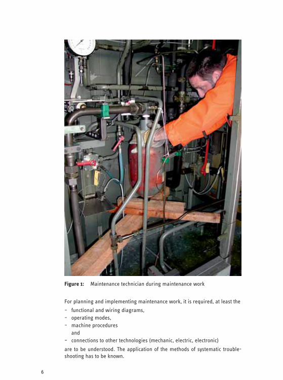
Figure 1: Maintenance technician during maintenance work
For planning and implementing maintenance work, it is required, at least the
– functional and wiring diagrams, – operating modes, – machine procedures and – connections to other technologies (mechanic, electric, electronic)
are to be understood. The application of the methods of systematic trouble-shooting has to be known.

7
If the knowledge mentioned above is insufficient, system-specific information have to be requested from the machine manufacturer.
Working on electric parts of machines and systems is subject to special haz-ards. Thus, this work must only be conducted by persons technically trained and instructed in electrotechnology, e.g. electricians.
1.3 Hazards when Working on Hydraulic Systems
Working on hydraulic systems can lead to the following hazards:
– uncontrolled leakage of the hydraulic medium, – accidental machine movements, – parts coming off or bursting, – skin diseases, – noise.
Uncontrolled leakage of the hydraulic medium
When lines rupture, when connection elements that are still pressurized, be-come loosened, when damaging hydraulic hose lassemblies (see figure 2), or when applying inadmissibly high forces, leaking hydraulic fluid has to be ex-pected. The consequences can be:
– damages to the eyes, – intrusion into the skin (intoxication), – danger of fire, if there are ignition sources, e.g. oils on hot surfaces, – slipping danger on work stations and traffic paths, – hazards due to accidental machine movements, – environmental hazards, e.g. intrusion into or release to the earth and/or
groundwater.
Inadmissibly high forces can occur due to
– improperly set pressure valves, – modifications, e.g. to throttles, – improperly designed valves (e.g. switching too quickly), – loads applied externally, – accidental boosters on cylinders.
Accidental machine movements can be triggered by
– accidental operation of control units and controllers, such as buttons, lev-ers, controlling light barriers, proximity switches, manual aids, as well as interferences by magnetic fields,
– errors in the control system, – energy separation, energy supply, residual energy, – parts failure, – contamination of the hydraulic fluid.
8
Residual energy in a system can be present if
– accumulators (hydraulic/pneumatic) exist in the system, – loads are maintained in elevated positions, – clamping forces exist, – there are tensions between parts.
Parts failure can result from e.g.
– excessive system pressure, – wear and tear and material fatigue, e.g. valve springs, – stuck valves, – overload due to excessive dynamic pressure peaks, – improper or contaminated hydraulic fluids.
Parts coming off or bursting can be the result of
– overloaded components, e.g. due to excessive operating pressures or pressure peaks,
– material fatigue, – parts selected improperly (wrong parts although standard parts; e.g. in-
correctly selected parts with insufficient strength or performance).
This also comprises whipping hydraulic hose assemblies ruptured on one end.
Contact with hydraulic fluids can lead to effects hazardous to skin (see sec-tion 2). Vapors of hydraulic fluids can irritate airways when inhaled.
Noise emissions are not only caused by the pump unit, even the noise of ma-chines generated during maintenance can cause a substantial level of noise, e.g. during troubleshooting, test operation and others. Thus, the maintenance technician of the hydraulic system has to wear ear protection in case of noise emissions hazardous for the health.
Depending on the maintenance works, one or more hazards can occur simul-taneously. Thus, several protective measures have to be used. The most im-portant protective measures are explained in the individual sections of this BG information. If required, references are made to other BG informations.
1.4 Electrical Hazards
Working on electric parts of machines and systems can result in special haz-ards, such as
– direct and indirect contact with live or conducting parts, – shock currents, – electric arcs/discharges, – voltage diversion, e.g. with improper grounding,
and especially hazards due to working in confined spaces, which also com-prise the interior of machines and metallic vehicle superstructures, see BG information “Working in confined spaces” (BGI 534).

9
Figure 2: Bursted hydraulic hose assembliy
Thus, these works must only be conducted by persons technically trained and instructed in electrotechnology, e.g. electricians.
1.5 Planning the Works
In most cases, accidents occur because no or insufficient organizational preparation of the maintenance works took place. Implementing the works when being pressed for time is another reason. Furthermore, often only re-pair work is performed instead of determining and remedying the reasons for the failure. Moreover, years of routine can lead to overestimation of one’s own capabilities or to misinterpretations, if the practiced way of working is no longer challenged.

10
A precondition for safe maintenance work is planning the work thoroughly, including considering or establishing maintenance instructions.
Planning comprises:
– the course of the procedure, – the selection of maintenance technicians according to their qualification, – the required number of maintenance technicians according to the extent
of the work to be performed and – the work equipment to be used, such as tools and devices.
When determining work steps, possible hazards have to be minimized by protective measures. If new hazards occur while implementing the works, these also have to be minimized by risk assessment and additional protective measures.
The maintenance instructions should include at least the following:
– notices on systematic troubleshooting (see section 3), – provision of components that may need to be replaced, special tools, and
aids, – securing the circuit breaker of the energy supply, for example electrical,
hydraulic, pneumatic., – reduction of residual energies (in connected parts as well), – support of elevated loads, – method(s) for reducing the system pressure, – checking the depressurized condition, – if required, further protective measures to be taken (see appendix 1 let-
ter B).
There have to be safe access to the points of contact, e.g. work platforms, special standing surfaces.
The most important safety measures for maintaining hydraulic systems can be summarized in the five finger rule of fluid technology:
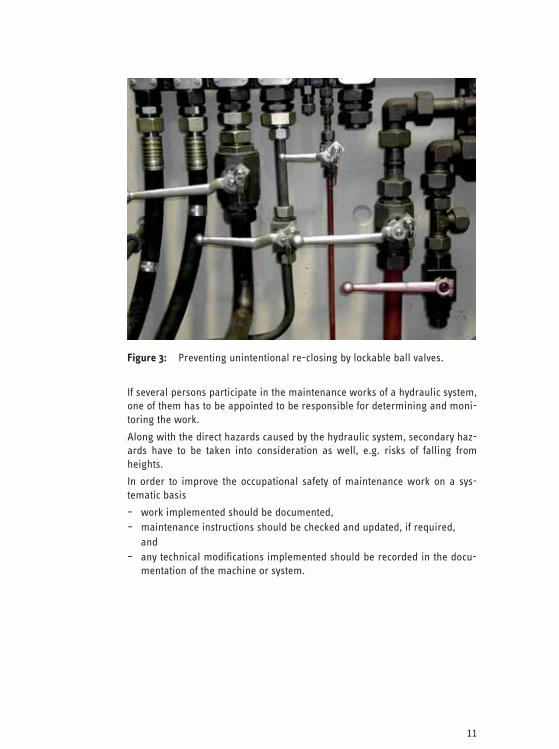
Note: Five finger rule of fluid technology: 1. Interrupt energy supply 2. Prevent unintentional re-closing (figure 3), 3. Depressurize the system, including all existing accumulators,
lower or support elevated loads, reduce residual energies 4. Check depressurization 5. Prevent hazards caused by adjacent systems
11
Figure 3: Preventing unintentional re-closing by lockable ball valves.
If several persons participate in the maintenance works of a hydraulic system, one of them has to be appointed to be responsible for determining and moni-toring the work.
Along with the direct hazards caused by the hydraulic system, secondary haz-ards have to be taken into consideration as well, e.g. risks of falling from heights.
In order to improve the occupational safety of maintenance work on a sys-tematic basis
– work implemented should be documented, – maintenance instructions should be checked and updated, if required, and – any technical modifications implemented should be recorded in the docu-
mentation of the machine or system.
12
N
o.: 0
00 S
ampl
e Op
erat
ing
inst
ruct
ions
acc
ordi
ng to
§ 1
4 Ge
fSto
ffV
(Ger
man
Ord
inan
ce o
n Ha
zard
ous
Subs
tanc
es)
Date
: 06.
12.2
006
Op
erat
ion:
Fi
eld
of a
pplic
atio
n: W
orks
hop,
war
ehou
se
Hy
drau
lic o
ils
Hyd
raul
ic o
ils w
ith h
igh
visc
osity
: Hig
hly
refin
ed m
iner
al o
ils w
ith a
dditi
ves
Ha
zard
s fo
r hu
man
bei
ngs
and
the
envi
ronm
ent
Hyd
raul
ic o
ils a
re fl
amm
able
. In
conn
ectio
n w
ith a
ir, v
apor
s em
itted
dur
ing
stro
ng h
eatin
g an
d at
omiz
ed s
pray
s ca
n fo
rm e
xplo
sive
mix
ture
s. C
loth
es s
oake
d w
ith o
il ar
e su
bjec
t to
an ig
nitio
n ha
zard
. Fr
eque
nt o
r lo
ng-t
erm
con
tact
with
the
prod
ucts
, clo
thes
soa
ked
with
oil
as w
ell,
can
caus
e sk
in d
isea
ses
su
ch a
s in
flam
mat
ion,
ski
n ra
sh, p
etro
leum
acn
e fo
r ex
ampl
e.
Prod
ucts
sub
ject
to h
igh
tem
pera
ture
s w
hile
bei
ng u
sed
can
accu
mul
ate
with
har
mfu
l Sub
stan
ces.
Le
akin
g hy
drau
lic o
il is
haz
ardo
us to
wat
ers.
Pr
otec
tive
mea
sure
s an
d ru
les
of c
ondu
ct
Stor
e an
d fil
l hyd
raul
ic o
ils a
bove
dri
p pa
ns o
nly,
avo
id s
plas
hing
. Do
not
ove
rfill
dri
p pa
ns w
ith c
onta
iner
s an
d do
not
use
dri
p pa
ns to
sto
re o
ther
mat
eria
ls.
Keep
aw
ay fr
om ig
nitio
n so
urce
s, d
o no
t sm
oke.
Do
not a
tom
ize
lubr
ican
ts.
Keep
con
tain
ers
clos
ed a
nd p
rote
ct a
gain
st h
eatin
g.
Stor
e so
aked
cle
anin
g cl
oths
in n
on-i
nfla
mm
able
, clo
sed
cont
aine
rs.
Repl
ace
clea
ning
clo
ths
on a
reg
ular
bas
is.
Labe
l fill
ed c
onta
iner
s, r
epla
ce fa
ulty
labe
ls.
Nev
er u
se fo
od c
onta
iner
s or
con
tain
ers
that
cou
ld p
ossi
bly
be c
onfu
sed
with
the
sam
e.
Han
d pr
otec
tion:
fo
r lo
ng-t
erm
, use
res
ista
nt g
love
s pr
otec
ting
agai
nst c
hem
ical
s Sk
in p
rote
ctio
n:
see
skin
pro
tect
ion
sche
me
Avoi
d co
ntac
t with
ski
n an
d cl
othe
s.
Take
off
soak
ed c
loth
es im
med
iate
ly a
nd r
e-w
ear
them
afte
r cl
eans
ing.
Do
not
put
use
d cl
eani
ng c
loth
s in
to th
e po
cket
s of
the
wor
king
clo
thes
. Af
ter
hand
ling
the
mat
eria
ls w
ash
your
han
ds a
nd a
pply
car
e cr
eme.
Do
not
use
any
sol
vent
s, th
inne
rs, b
enzi
ne o
r ot
hers
for
skin
cle
anin
g pu
rpos
es.
Be
havi
or in
cas
e of
dan
ger
(em
erge
ncy
tele
phon
e: s
ee p
laca
rd)

13
Af
ter
leak
age
imm
edia
tely
soa
k up
usi
ng o
il bi
nder
(....
......
......
......
......
) and
pla
ce in
to w
aste
con
tain
er; v
entil
ate
room
th
orou
ghly
. Cau
tion:
Slip
haz
ard
due
to s
lippe
ry fl
oor.
Fire
ext
ingu
ishe
r fo
r fir
e cl
ass
B, n
o w
ater
. ....
......
......
......
......
In c
ase
of fi
re th
ere
is th
e da
nger
of b
urst
ing
clos
ed h
eate
d co
ntai
ners
.
Leav
e oi
l war
ehou
se in
cas
e of
dan
ger.
Esca
pe r
oute
: se
e id
entif
icat
ion
of th
e es
cape
rou
tes
and
emer
genc
y ex
its
Fi
rst a
id (f
irst
aid
er: s
ee p
laca
rd)
Afte
r sk
in c
onta
ct:
was
h th
orou
ghly
usi
ng s
oap
and
wat
er, t
ake
off s
oake
d cl
othe
s be
fore
hand
.
Afte
r ey
e co
ntac
t:
with
ope
n pa
lpeb
ral f
issu
re a
nd in
dir
ectio
n of
the
exte
rnal
pal
pebr
al fi
ssur
e flu
sh
for
10 m
inut
es w
ith r
unni
ng w
ater
, con
tact
eye
spe
cial
ist.
Afte
r sw
allo
win
g:
Do n
ot s
timul
ate
vom
iting
, con
tact
a d
octo
r.
Afte
r oi
l inj
ectio
n:
e.g.
afte
r su
bcut
aneo
us in
trus
ion
of o
il co
ntac
t doc
tor
imm
edia
tely
!
Ap
prop
riat
e di
spos
al
Co
llect
was
tes
in la
bele
d, n
on-i
nfla
mm
able
con
tain
ers
(.....
......
......
......
.....)
; kee
p w
aste
con
tain
ers
and
empt
y co
ntai
ners
clo
sed,
em
pty
cont
aine
rs a
t the
end
of t
he s
hift
at th
e la
test
or
rem
ove
from
the
wor
k ar
ea.
Da
te, S
igna
ture
: ....
......
......
......
......
......
......
..
So
urce
: ww
w.b
ggla
sker
amik
.de
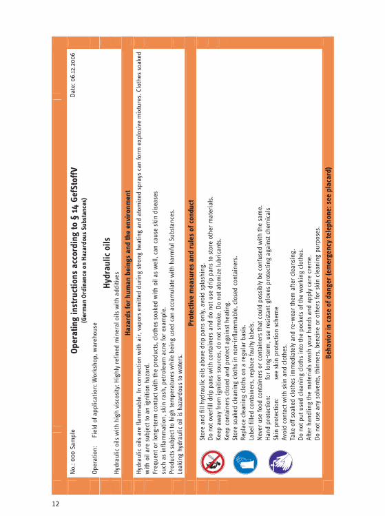
Figu
re 4
: Sa
mpl
e of
ope
ratin
g in
stru
ctio
ns fo
r hy
drau
lic o
il

14
2 Handling Hydraulic Fluid
2.1 Skin Protection
Maintenance technicians for hydraulic systems are used to having “dirty hands” at work. The intensive daily skin cleansing procedure apparently is tolerated without any problems, so that the engineers normally do not think about the fact if the skin – the largest human organ – tolerates this without being damaged on a continuing basis. The alloy components and additives contained in the oils and fats can have allergizing or sensitizing effects.
A lack of consciousness for the aforementioned is one reason that skin dis-eases range amongst the most frequent work-related diseases in metal-processing companies.
The organ skin is the link between the human immune system on the one hand and the “external world” on the other hand. Especially the fats on the external skin layer form an efficient but vulnerable protection against harmful influences. Frequent washing, especially with substances solving the fats, damages this protective layer. If the body is no longer able to repair these damages within the work breaks, the result is dry skin with formation of rup-tures and redness, shortly the “wear eczema”. Secondly, often an “allergic eczema” additionally “engrafts” during the further course, as substances po-tentially causing allergies can intrude into deeper regions of the skin organ more easily if the skin is already damaged. Depending on the personal dispo-sition, such reactions can occur a relative short time after the first skin expo-sures or after many years or decades of executing skin exposing activities.
If a work-related allergic skin disease has established, the consequences – professional and private – often are serious. As contact with substances caus-ing allergies normally cannot be prevented completely, losing the job is pos-sible.
What can be done?
There are many options for maintaining a mostly healthy skin during strongly contaminating activities. Firstly, the most important precondition is that eve-rybody develops the proper understanding for the vulnerability of his own skin.
The entrepreneur is responsible for regulating skin protection within the company, e.g. using a skin protection scheme. In doing so, specialists (com-pany physician, supervisor) should be integrated and corporate experience should be taken into consideration.
2.1.1 Work Clothes
No special protective clothes are specified for the maintenance technician for hydraulic systems. Work clothing worn and contaminated in addition to or to protect the private clothes have to be cleansed on a regular basis. There should be at least two, better three overalls for every maintenance technician,
15
in order to provide for immediate replacement even in case of unforeseeable contaminations with hydraulic fluids.
Note: Contaminated clothes have to be taken off immediately. Contaminated cleaning rags must not be put into the trousers.
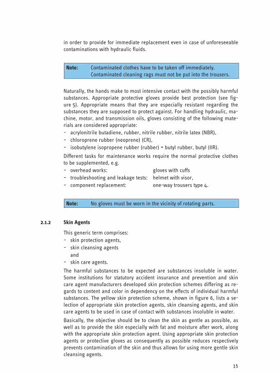
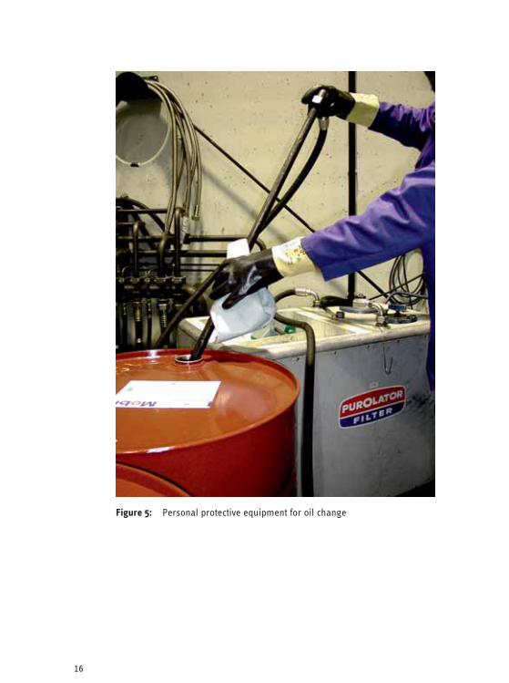
Naturally, the hands make to most intensive contact with the possibly harmful substances. Appropriate protective gloves provide best protection (see fig-ure 5). Appropriate means that they are especially resistant regarding the substances they are supposed to protect against. For handling hydraulic, ma-chine, motor, and transmission oils, gloves consisting of the following mate-rials are considered appropriate: – acrylonitrile butadiene, rubber, nitrile rubber, nitrile latex (NBR), – chloroprene rubber (neoprene) (CR), – isobutylene isopropene rubber (rubber) = butyl rubber, butyl (IIR).
Different tasks for maintenance works require the normal protective clothes to be supplemented, e.g. – overhead works: gloves with cuffs – troubleshooting and leakage tests: helmet with visor, – component replacement: one-way trousers type 4.
Note: No gloves must be worn in the vicinity of rotating parts.
2.1.2 Skin Agents
This generic term comprises: – skin protection agents, – skin cleansing agents and – skin care agents.
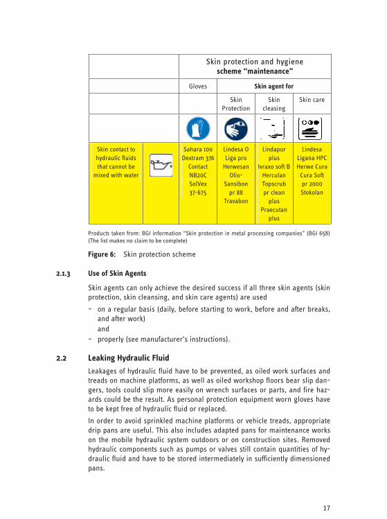
The harmful substances to be expected are substances insoluble in water. Some institutions for statutory accident insurance and prevention and skin care agent manufacturers developed skin protection schemes differing as re-gards to content and color in dependency on the effects of individual harmful substances. The yellow skin protection scheme, shown in figure 6, lists a se-lection of appropriate skin protection agents, skin cleansing agents, and skin care agents to be used in case of contact with substances insoluble in water.
Basically, the objective should be to clean the skin as gentle as possible, as well as to provide the skin especially with fat and moisture after work, along with the appropriate skin protection agent. Using appropriate skin protection agents or protective gloves as consequently as possible reduces respectively prevents contamination of the skin and thus allows for using more gentle skin cleansing agents.
16
Figure 5: Personal protective equipment for oil change
17
Skin protection and hygiene scheme “maintenance”
Gloves Skin agent for
Skin Protection
Skin cleasing
Skin care
Skin contact to hydraulic fluids that cannot be
mixed with water
Sahara 100
Dextram 376 Contact NB20C SolVex 37-675
Lindesa O Liga pro
Herwesan Olio-
Sansibon pr 88
Travabon
Lindapur plus
Ivraxo soft BHerculan Topscrub pr clean
plus Praecutan
plus
Lindesa Ligana HPCHerwe Cura
Cura Soft pr 2000 Stokolan
Products taken from: BGI information “Skin protection in metal processing companies” (BGI 658) (The list makes no claim to be complete)
Figure 6: Skin protection scheme
2.1.3 Use of Skin Agents
Skin agents can only achieve the desired success if all three skin agents (skin protection, skin cleansing, and skin care agents) are used
– on a regular basis (daily, before starting to work, before and after breaks, and after work)
and – properly (see manufacturer’s instructions).
2.2 Leaking Hydraulic Fluid
Leakages of hydraulic fluid have to be prevented, as oiled work surfaces and treads on machine platforms, as well as oiled workshop floors bear slip dan-gers, tools could slip more easily on wrench surfaces or parts, and fire haz-ards could be the result. As personal protection equipment worn gloves have to be kept free of hydraulic fluid or replaced.
In order to avoid sprinkled machine platforms or vehicle treads, appropriate drip pans are useful. This also includes adapted pans for maintenance works on the mobile hydraulic system outdoors or on construction sites. Removed hydraulic components such as pumps or valves still contain quantities of hy-draulic fluid and have to be stored intermediately in sufficiently dimensioned pans.
18
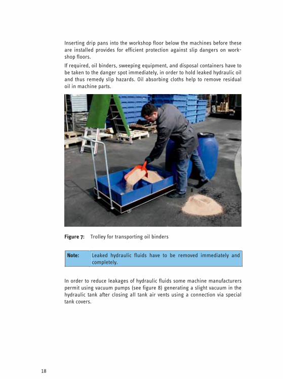
Inserting drip pans into the workshop floor below the machines before these are installed provides for efficient protection against slip dangers on work-shop floors.
If required, oil binders, sweeping equipment, and disposal containers have to be taken to the danger spot immediately, in order to hold leaked hydraulic oil and thus remedy slip hazards. Oil absorbing cloths help to remove residual oil in machine parts.
Figure 7: Trolley for transporting oil binders
Note: Leaked hydraulic fluids have to be removed immediately and completely.
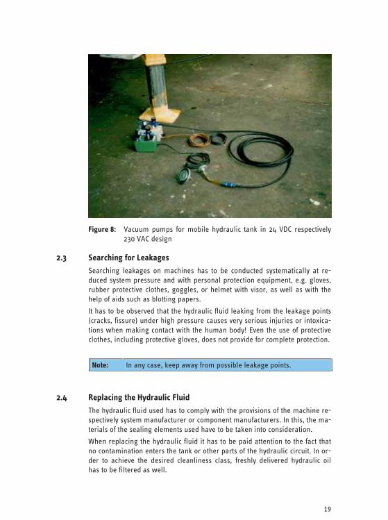
In order to reduce leakages of hydraulic fluids some machine manufacturers permit using vacuum pumps (see figure 8) generating a slight vacuum in the hydraulic tank after closing all tank air vents using a connection via special tank covers.
19
Figure 8: Vacuum pumps for mobile hydraulic tank in 24 VDC respectively 230 VAC design
2.3 Searching for Leakages
Searching leakages on machines has to be conducted systematically at re-duced system pressure and with personal protection equipment, e.g. gloves, rubber protective clothes, goggles, or helmet with visor, as well as with the help of aids such as blotting papers.
It has to be observed that the hydraulic fluid leaking from the leakage points (cracks, fissure) under high pressure causes very serious injuries or intoxica-tions when making contact with the human body! Even the use of protective clothes, including protective gloves, does not provide for complete protection.
Note: In any case, keep away from possible leakage points.
2.4 Replacing the Hydraulic Fluid
The hydraulic fluid used has to comply with the provisions of the machine re-spectively system manufacturer or component manufacturers. In this, the ma-terials of the sealing elements used have to be taken into consideration.
When replacing the hydraulic fluid it has to be paid attention to the fact that no contamination enters the tank or other parts of the hydraulic circuit. In or-der to achieve the desired cleanliness class, freshly delivered hydraulic oil has to be filtered as well.
20
3 Troubleshooting Obviously, preventive maintenance and repair measures, especially checking the oil cleanliness on a regular basis, are the best method to minimize errors and failures in the run-up already. Nevertheless, errors and failures influenc-ing the general operation sequence but also the safety of the hydraulic sys-tem or machines can occur when operating an hydraulic system or machine.
Along with influences on product quality, this can lead to hazards (see sec-tion 1.3) making working with the machine in a safe manner impossible.
Thus, it is important that the machine operator reports all failures and errors to the supervisor or the maintenance department immediately. These persons decide whether it is possible to continue to work with the machine or whether the machine has to be repaired immediately.
Note: Errors in hydraulic systems or machines have to be reported to the supervisor immediately.
Before starting troubleshooting, the procedure has to be determined. Along with planning the proper troubleshooting, this also comprises the measures for securing the work area (i.e. the danger and effective range), as well as the required protective measures.
Note: Troubleshooting and repair work must be conducted only by trained personnel.
At the beginning of troubleshooting, the required technical documents and information should be present, e.g. operating instructions, circuit and electri-cal diagrams, including measuring points, list of items. If no hydraulic circuit diagram can be found for older systems, a circuit sketch should be estab-lished on the basis of design, signposting, and labeling of the parts.
The machine operators should be questioned regarding error behavior, fail-ures, and reactions of the machine and system. If a maintenance book or log exists, it should be used to investigate if this or similar failures already have occurred. Furthermore, the error lists in the operating instructions of the manufacturer have to be taken into consideration.
Note: Troubleshooting requires technical documents of the system/ machine.
If troubleshooting requires deviating from the normal ways of operation (e.g. test runs, installation, commissioning, respectively localizing the errors re-quires the faulty machine to be operated for one or several cycles), it must be
21
ensured that safeguarding equipment (movable safeguarding equipment, two-hand control devices, light barriers) on the machine is active in this phase as well. On the basis of the error that occurred, further (including or-ganizational) measures may have to be taken in dependency on the machine, in order to avoid employees being endangered during troubleshooting (wide area safety fence using chains, instruction plates, reduced speed, and re-duced pressure).
During troubleshooting operating modes should be used, for which individual functions are operated outside of automatic operation at reduced speeds, tip operation (hold-to run control device), enabling switch, or in operating mode “Installation/Hand”.
Attention must be paid to the fact that dangerous follow-up movements are triggered when passing position switches, e.g. also for automatic program-controlled tool and work piece replacement, start-up of accessory devices.
Note: Troubleshooting must only be conducted with safeguarding equipment activated.
If required, further organizational measures are necessary.
If troubleshooting also can be implemented with the machine turned off or if the machine is turned off for error correction after localizing the error, the five finger rule mentioned in section 1.5 has to be observed.
Note: Observe the five finger rule of fluid technology:
If the control system is not a purely hydraulic system, but the hydraulic sys-tem is operated as part of an electro-hydraulic control system, it may be nec-essary to have the troubleshooting procedure conducted by a specialist elec-trician. In case of complex systems operated with electronic control systems, it may also be necessary to call a specialist for electronic hardware or soft-ware. In this case, if several persons work on the machine for troubleshoot-ing purposes, it is imperative to provide for sufficient coordination of the ac-tivities on the machine. This especially applies if the machine operator has to be incorporated into the activities.
Furthermore, hazards caused by adjacent systems or for persons working on adjacent systems have to be prevented.
Note: For electro-hydraulic systems a specialist for electrical engineer-ing or electronics has to be called.
Activities of several persons have to be coordinated.

22
Even when pressed for time, following a systematic and targeted procedure is imperative, as random blindfold disassembly or adjustment activities could result in no longer being able to find the initial error.
It is recommended to document the implemented work steps, adjustment values, as well as their modifications. All modifications to the system must be documented in a traceable manner, e.g. in the machine documentation and, if required, in a maintenance book or log.
A list of remedied failures and error reasons supports troubleshooting proce-dures in the future.
Many hydraulic system manufacturers have developed comprehensive service information and described possible malfunctions and their reasons or possi-ble sources, as well as measures for remedying them systematically in these documents, as the technical reasons for error and the measures for remedy can vary.
Appendix 1 letter A shows a general troubleshooting tree for hydraulic com-ponents.
Typical errors include for example:
– clogged hydraulic filters, – stuck valves due to contaminations, – unexpected start-up of the machine due to tipping/triggering position/stop
switches, – failure of valves due to spring rupture.
The reason for part failure should be determined.
Notes:
If the hydraulic energy must be maintained for troubleshooting or due to other reasons, the provisions of the manufacturer must be observed.
Regarding the re-commissioning procedure, further safeguarding measures must be observed, see sections 5.1.2 and 6.1.9.
4 Working on Hydraulic Components 4.1 General
When working on hydraulic components, numerous safety-relevant aspects have to be observed by the maintenance technician. Sections 5 and 6 deal with the particularities for certain machines and systems, as well as the mo-bile hydraulic system.
Basically, only spare parts approved by the manufacturer should be replaced respectively installed.
It is imperative to observe provisions and notices of the manufacturer regard-ing special knowledge or training of the maintenance technician.

23
The hydraulic system must be protected against contamination introduced from the outside as far as possible. Flushing provisions specified by the manufacturer must be observed. Spare parts to be installed must be free of contaminations.
All parts installed by the maintenance technician must be selected in accor-dance with the operating pressures and hydraulic fluids.
Due to the partially relative high masses of the installation position and the position of the center of gravity of hydraulic components, suitable lifting gear and lifting accessories must be designed for disassembly and assembly, as well as transportation.
If it is possible to confuse line connections , these must be marked clearly by the maintenance technician before being disconnected.
It is imperative to observe the provisions of the manufacturer regarding commissioning after completed maintenance works.
Figure 9: Central hydraulic system at commissioning
4.2 Pipelines
Pressurized fittings of pipelines must not be opened.
If pipelines have to be replaced, standardized cold-drawn precision steel pipes have to be used. When selecting these pipes the pipe cross sections and the admissible operating pressures have to be observed.
Some connection element manufacturers rate the nominal pressures in de-viation from the standards. Thus, parts having the same dimensions can be characterized by substantial differences regarding the nominal pressures.
24
Similar thread sizes of different systems (metric/inched) must not be con-fused!
Note: When procuring spare parts, attention must be paid to the fact that parts having the same dimensions can have different nomi-nal pressures and thread types.
If pipelines have to be re-routed within the framework of maintenance works, these have to be attached by pipe clamps in a sufficient manner. The follow-ing distances have proven to be of value:
External line diameter Attachment distance
up to 10mm 1 m
over 10mm up to 25mm 1.5 m
over 25mm up to 50mm 2.0 m
over 50mm 3.0 m
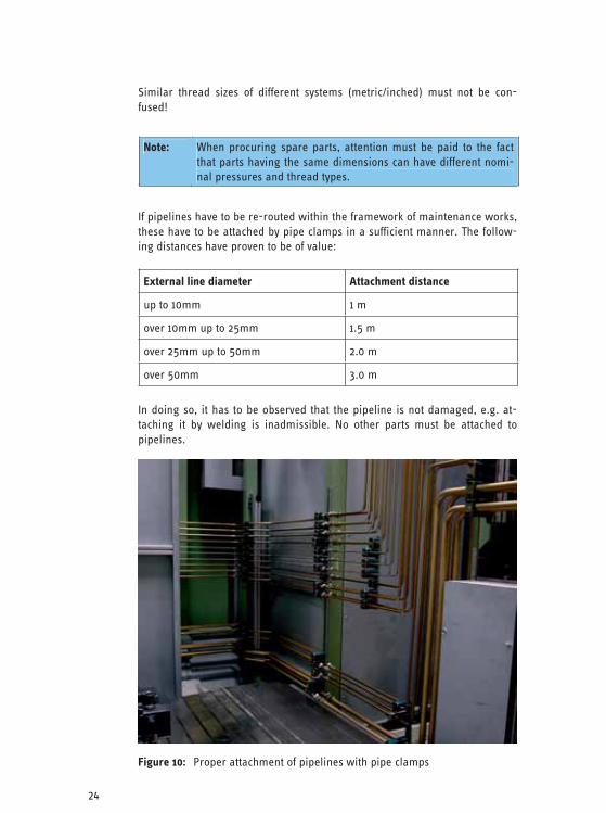
In doing so, it has to be observed that the pipeline is not damaged, e.g. at-taching it by welding is inadmissible. No other parts must be attached to pipelines.
Figure 10: Proper attachment of pipelines with pipe clamps

25
The pipe elbows must be bent taking the bending radii into consideration and using appropriate devices, e.g. pipe bending machine. Pipes must not be buckled when they are bent. Pipes subjected to heat treatment must be cleansed and descaled.
Before being installed into the pipeline systems, pipeline components always must be deburred, cleansed, and installed in accordance with the provisions of the fitting suppliers.
If it is possible to confuse line connections, these must be marked clearly and permanently by the maintenance technician before being disconnected.
During assembly, the newly installed connections have to be tightened in ac-cordance with the manufacturer’s instructions, e.g. using the torque wrench or according to specified angle of twist, in order to avoid shear forces and tensions.
Pipelines and fittings have to be checked for leaks up to maximum operating pressure before they can be approved.
If pipeline fittings show leakages, these have to be remedied. For this, de-pressurized condition has to be established first. Afterwards, the following measures can be implemented:
– re-tightening the fittings, – re-tightening the flange connections, – replacing the seals.
Figure 11: Pipeline routing in a large machine
26
4.3 Hoses
4.3.1 General
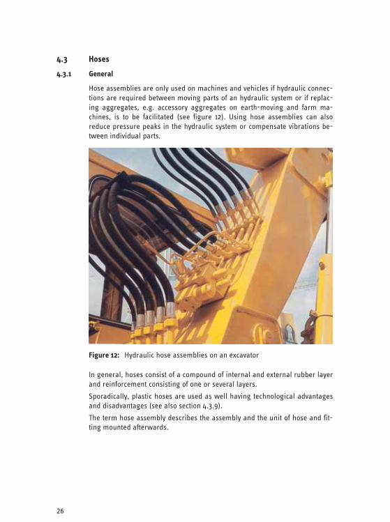
Hose assemblies are only used on machines and vehicles if hydraulic connec-tions are required between moving parts of an hydraulic system or if replac-ing aggregates, e.g. accessory aggregates on earth-moving and farm ma-chines, is to be facilitated (see figure 12). Using hose assemblies can also reduce pressure peaks in the hydraulic system or compensate vibrations be-tween individual parts.
Figure 12: Hydraulic hose assemblies on an excavator
In general, hoses consist of a compound of internal and external rubber layer and reinforcement consisting of one or several layers.
Sporadically, plastic hoses are used as well having technological advantages and disadvantages (see also section 4.3.9).
The term hose assembly describes the assembly and the unit of hose and fit-ting mounted afterwards.

27
Hose Assembly = Hose + Fitting
Figure 13: Structure and labeling of a hose assembly

28
Faulty integration, ageing, and mechanical damage can result in the hose as-semblies bursting. Thus, corresponding care should be exerted when select-ing, assembling, mounting, and operating hose assemblies.
A hose has to be labeled as follows, see BG rule “Hydraulic hose assemblies” (BGR 237):
– manufacturer sign, – hose type, – nominal width, – date of manufacture (quarter and year), as well as the standards mark.
A hose assembly has to be labeled as follows:
– manufacturer’s name or short sign, – maximum operating pressure in bar, – date of manufacture (year/month), see also DIN EN 982.
Note: Hoses and hose assembly of unknown origin or being labeled incompletely must not be used!
4.3.2 Selection of Hose, Fitting, and Hose Assembly for Replacement
In principle, hoses have to be replaced in accordance with the manufacturer’s instructions. If no manufacturer details are available, the following procedure has to be followed:
Hose, fitting, and hose assembly have to be selected in a way that
– the admissible loads of the parts are not exceeded for the operating pres-sures to be expected,
– those operating pressures are taken into account the control system has been designed for,
– the cross sections are dimensioned sufficiently, so that no inadmissible dynamic pressures are generated that for example could impair the free return to the tank,
– the compatibility of hose and sealing materials with the hydraulic fluid used is given
– only parts are used that comply with the requirements of European or in-ternational product standards, such as EN, ISO, SAE standards,
– designs of hose assembly fittings consisting of a (drilled) pipe socket with olive are not used, as these do no longer correspond to the state-of-the-art and have led to accidents due to slipping tools in the past.
Note: It has to be checked if the hose assembly is suitable for the in-tended use regarding pressure and volumetric flow.
29
4.3.3 Creating a Hose assembly
It is recommended to purchase hose assemblies as fully assembled parts. When making a hose assembly by oneself, it has to be observed that the se-lected parts (hose and fitting) are compatible regarding their dimensions, shape, and pressure stage. For this, it is imperative to observe the provisions of the manufacturers of hose and fitting.
If the integration is conducted by oneself, only equipment and devices ap-proved by the manufacturer must be used for this. Integrating the hose in a secure way furthermore implies detailed knowledge of the integration proce-dure, the devices, and parts. Conducting the integration without this knowl-edge and without these devices is negligent and inadmissible from the point of view of safety.
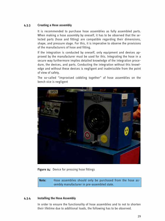
The so-called “improvised cobbling together” of hose assemblies on the bench vice is negligent
Figure 14: Device for pressing hose fittings
Note: Hose assemblies should only be purchased from the hose as-sembly manufacturer in pre-assembled state.
4.3.4 Installing the Hose Assembly
In order to ensure the functionality of hose assemblies and to not to shorten their lifetime due to additional loads, the following has to be observed.
30
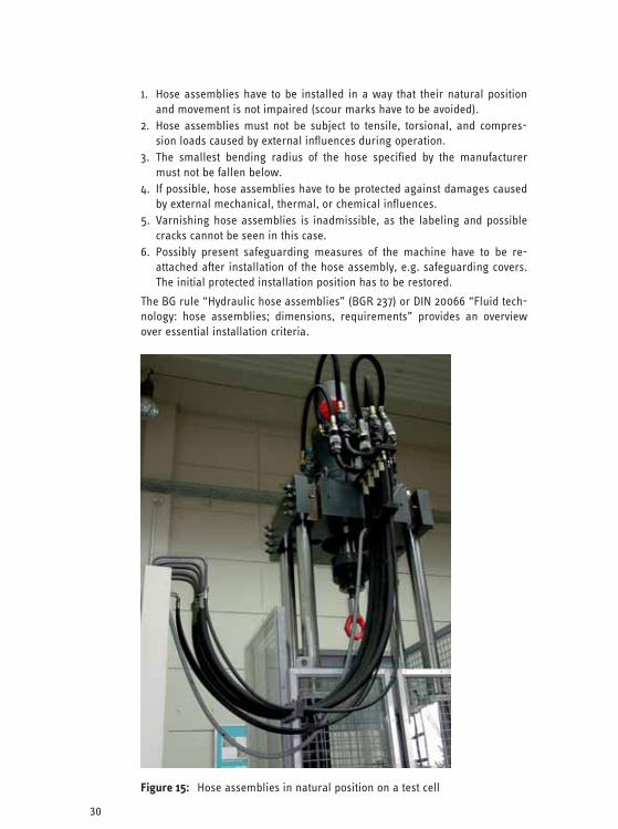
1. Hose assemblies have to be installed in a way that their natural position and movement is not impaired (scour marks have to be avoided).
2. Hose assemblies must not be subject to tensile, torsional, and compres-sion loads caused by external influences during operation.
3. The smallest bending radius of the hose specified by the manufacturer must not be fallen below.
4. If possible, hose assemblies have to be protected against damages caused by external mechanical, thermal, or chemical influences.
5. Varnishing hose assemblies is inadmissible, as the labeling and possible cracks cannot be seen in this case.
6. Possibly present safeguarding measures of the machine have to be re-attached after installation of the hose assembly, e.g. safeguarding covers. The initial protected installation position has to be restored.
The BG rule “Hydraulic hose assemblies” (BGR 237) or DIN 20066 “Fluid tech-nology: hose assemblies; dimensions, requirements” provides an overview over essential installation criteria.
Figure 15: Hose assemblies in natural position on a test cell
31
Note: When installing hose assemblies, it is imperative to observe the installation instructions of the hose manufacturer, e.g. minimum bending radii.
4.3.5 Regular Check of Hose assemblies
Due to ageing, wear and tear, and damages the hose assemblies have to be checked on a regular basis.
For this, the hose assemblies have to be checked for external deficiencies (visually) by an authorized person at least once a year; see also BG rule „Hy-draulic hose assemblies” (BGR 237). If the manufacturer makes concrete pro-visions regarding the aforementioned, these have to be observed.
Further notices regarding authorized persons (formerly known as techni-cal experts), tests, and test intervals, see section 7.
These tests have to be documented together with the date in a test log, e.g. when testing the machine.
The test criteria are:
– damages of the external layer up to the insert (scour marks, cuts, cracks), – embrittlement of the external layer (formation of cracks in the hose mate-
rial), – deformations not corresponding to the natural shape of the hose assem-
bly, in pressurized or depressurized condition or when bent, e.g. layer separation, formation of bubbles, pinch points, knees,
– leakages on the hose, the hose assembly, or the fitting, – the hose coming out of the fitting, – damages or deformations to fittings reducing the functionality and
strength of the fittings or of the connection fitting-hose, – corrosion of the fitting reducing the functionality and the strength, – Can the hose assemblies still move freely or are there pinch, shear, or
scour points caused by attaching new parts of the system or aggregates? – Do hose assemblies project into traffic paths, also when the aggregates
connected via hose assemblies are driven to their respective end posi-tions?
– Have hose assemblies been varnished (explanation: cracks and labeling cannot be seen!)?
– Have the storage periods and the lifetime been exceeded? – Have all covers been re-mounted after the test? – Are there additional stripping protections or are they required?
Note: Hose assemblies have to be checked at regular intervals.

32
4.3.6 Faulty Hose Assemblies
If deficiencies regarding the safe condition of a hose assembly are detected during the test, the corresponding hose assembly has to be replaced. Hose assemblies must not be repaired and must not be assembled from old parts.
Figure 16: Examples for failed hydraulic hose assemblies
If several hose assemblies are replaced simultaneously, it has to be ensured that the connections cannot be confused, e.g. by marking them.
Note: Faulty hose assemblies have to be replaced immediately!
4.3.7 Lifetime of Hose Assemblies
Basically, hoses and hose assemblies are subject to a natural ageing process even if they are stored properly and operated under admissible loads. This ageing process reduces the performance of the hose assemblies. Thus, the lifetime of a hose assembly is limited.
The possible lifetime (i.e. period of use) of hose assemblies especially de-pends on the operation and environmental conditions. Due to the wide range of applications for hose assemblies it is thus not possible to specify a binding, maximum admissible lifetime in safety rules and regulations and standards due to technical reasons.
33
The instructions of the hose and hose assembly manufacturers regarding the maximum storage time have to be observed. When producing the hose as-sembly the hose should not be much older than four years.
When determining the lifetime for the corresponding hose assemblies used on a machine, the user first and foremost has to base his decision on the re-placement intervals recommended by the machine manufacturer, but also on his own experience regarding his individual operating conditions. This espe-cially applies when the lifetime recommended by the manufacturer is ex-ceeded. Prolonging the lifetime is possible if
– corresponding test values and experience on part of the operator or the hose and hose assembly manufacturers are present,
– a risk assessment has been conducted by the operator that considered secondary safeguarding measures against hazards caused by hose assem-bly failures as well,
and – the test for safe condition is implemented at appropriate intervals and by
an authorized person.
For the recurring test it should be clarified if the preconditions that lead to the determination of a certain lifetime have changed, e.g. higher system pressures, changed location of installation.
It is absolutely recommendable to shorten the test intervals, e.g. to biannually or quarterly (instead of at least annually), when prolonging the lifetime.
Unless there are other specifications regarding the lifetime of hydraulic hose assemblies, six years are recommended as reference value, see also BG rule “Hydraulic hose assemblies” (BGR 237).
4.3.8 Securing the Environment in Case of Hose Assemblies Failures
In general, hose assemblies perform their task without any problems when they are designed and selected properly, produced carefully, and installed correctly.
However, it has to be considered that failures of hose assemblies, e.g. near work stations and traffic paths, can lead to hazards, e.g.:
– leakage of hydraulic fluid at high pressure, – lashing and – fire hazard.
Thus, additional measures for safeguarding the environment in case of hose assembly failures have to be taken at those points, e.g. by means of addi-tional stripping protection or screening.
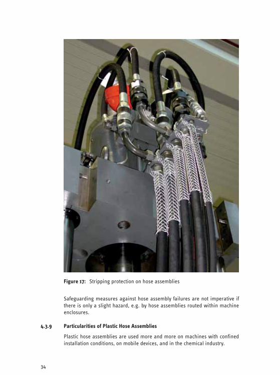
34
Figure 17: Stripping protection on hose assemblies
Safeguarding measures against hose assembly failures are not imperative if there is only a slight hazard, e.g. by hose assemblies routed within machine enclosures.
4.3.9 Particularities of Plastic Hose Assemblies
Plastic hose assemblies are used more and more on machines with confined installation conditions, on mobile devices, and in the chemical industry.

35
The technological advantages of the plastic hose assemblies are:
– 20 to 30% weight reduction, – reduced external diameter and minimum bending radius, – higher milling and abrasion resistance, – good resistance against diverse chemical substances, as well as – low sensitivity regarding water-containing cooling lubricants, – no or only low influence of ageing during storage time before use, – relatively low price, especially for small nominal widths.
The disadvantages are:
– higher breathing volume, – higher loss of elasticity after longer periods of use, – lower torsional strength, thus twisting possible during installation, – higher sensitivity regarding mechanical damages, especially if reinforce-
ments consist of plastic yarn meshwork, – higher sensitivity regarding UV radiation, thermal radiation, and liquid
metal, e.g. welding beads, – higher sensitivity of the external layer regarding cutting oils (however, de-
pending strongly on the material).
The advantages and disadvantages of plastic hose assemblies mentioned above have to be taken into consideration during design, selection, and in-stallation.
Section 4.3.7 is valid regarding lifetime, replacement, and installation.
Possible exclusions regarding the use on part of the manufacturers have to be observed.
4.4 Hydraulic Cylinders
Before starting to replace hydraulic cylinders, these have to be free of all forces, e.g. caused by elevated loads. Furthermore, it has to be paid attention to the fact that depressurization is implemented on both the piston and the rod side.
The technical data of replacement cylinders have to comply with those of the types to be replaced.
In order to prevent unforeseeable sudden parts movements caused by resid-ual air in the cylinders, these have to be filled with hydraulic fluid and vented by several extracting and retracting procedures in idle in the service work-shop or via the system hydraulics before they are installed. If this is not im-plemented automatically, the ventilation has to be implemented manually on the piston and rod side. In doing so, possibly existing bleeding screws have to be used. The fittings must only be re-tightened when the leaking oil is free of bubbles.
If sealing plugs are used after the hydraulic cylinders have been filled, it is important to remove these before installation. This is particularly important on the piston rod side, in order to avoid pressure transmissions.
36
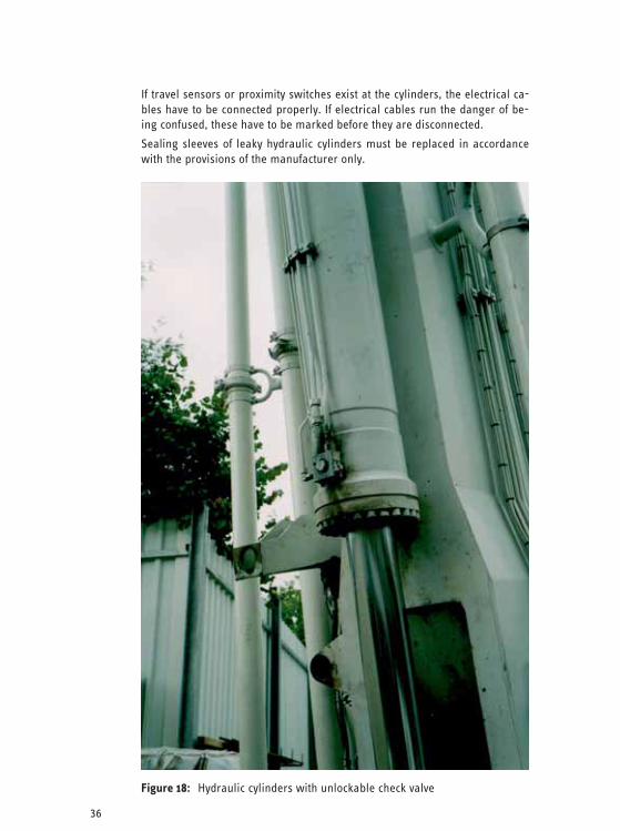
If travel sensors or proximity switches exist at the cylinders, the electrical ca-bles have to be connected properly. If electrical cables run the danger of be-ing confused, these have to be marked before they are disconnected.
Sealing sleeves of leaky hydraulic cylinders must be replaced in accordance with the provisions of the manufacturer only.
Figure 18: Hydraulic cylinders with unlockable check valve
37
When replacing the hydraulic cylinder, a possibly existing piston rod protec-tion, e.g. sleeve or sheet metal cover, has to be re-installed after installation.
After having replaced a cylinder of a clamping device in particular, the ma-chine or the system must be approved for the operator after sufficient test runs only.
In order to attach cylinders, parts approved by the manufacturer must be used only (such as screws in the required property class). The details regard-ing thread design and screw-in length have to be observed. When working on parts of an hydraulic cylinder, including seals, cleanliness has to be top priority.
4.5 Pumps and Motors
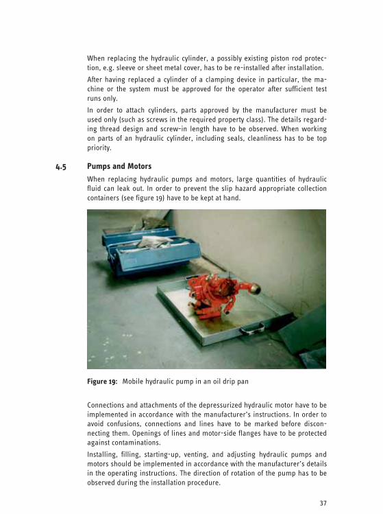
When replacing hydraulic pumps and motors, large quantities of hydraulic fluid can leak out. In order to prevent the slip hazard appropriate collection containers (see figure 19) have to be kept at hand.
Figure 19: Mobile hydraulic pump in an oil drip pan
Connections and attachments of the depressurized hydraulic motor have to be implemented in accordance with the manufacturer’s instructions. In order to avoid confusions, connections and lines have to be marked before discon-necting them. Openings of lines and motor-side flanges have to be protected against contaminations.
Installing, filling, starting-up, venting, and adjusting hydraulic pumps and motors should be implemented in accordance with the manufacturer’s details in the operating instructions. The direction of rotation of the pump has to be observed during the installation procedure.
38
When assembling pump, suction line, and tank it has to be observed that the suction filter is installed properly.
The safeguarding equipment has to be re-installed before commissioning.
4.6 Valve Blocks
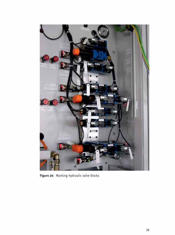
In order to prevent confusions, the individual connections of the valves re-spectively the tower-type interlinkages of valve blocks have to be numbered respectively marked before being disassembled (see figure 20).
Valves must be assembled and disassembled exerting the utmost care and cleanliness only. During the installation the O-ring sealing elements within valve interlinkages have to be checked for proper seat.
All technical data (including wiring symbols and adjustment values) of replacement valves have to comply with the provisions of the manufacturer respectively with the data of the type to be replaced.
The valves/valve blocks have to be assembled observing the order of the in-terlinkages. In doing so, the installation position specified by the manufac-turer has to be observed. The selected attachment screws have to comply with the dimensions and property classes specified in the valve data sheet. The screws have to be attached evenly and exactly with the torque specified in the valve data sheet as well.
When replacing faulty switching magnets on valves the required voltages and performance details have to be observed. Magnets for 24 Volts operation do not execute the switching function when operated with 12 Volts for example.
When installing replacement valves of other manufacturers the electric pin assignments of the connection plugs have to be observed. These can be found in the related valve data sheet.
4.7 Accumulator Systems
Accumulators are devices the manufacturer has to meet special safety provi-sions for. Furthermore, the operator of work equipment has to observe the provisions for the tests in accordance with the operational safety regulations (see section 7).
As maintaining and filling accumulators with gas, measuring pressures, and testing after commissioning require special knowledge, works on accumula-tor systems must only be conducted by especially trained maintenance tech-nicians or by the manufacturer. It is imperative to observe the provisions of the manufacturer in the operating instructions.
Before working on the accumulator, the pressure in the accumulator has to be reduced, along with the system hydraulics. This is implemented either automatically or via a manual depressurization at the accumulator safety block. A pressure indicator, e.g. manometer, has to be used to check the effi-ciency of the depressurization procedure. It has to be observed that the ac-cumulator may be under high pressure on the gas side. It may be required to reduce this pressure as well.
39
Figure 20: Marking hydraulic valve blocks

40
Figure 21: Warning note on system with accumulator
New or repaired accumulators on oil-hydraulic systems are delivered pres-surized with nitrogen (under pressure) on the gas side, in order to protect them against transportation damages.
Before commissioning, these accumulators have to be charged to the charg-ing pressure specified in the hydraulic scheme using nitrogen.
Note: Due to an existing danger of explosion, oxygen or air must not be used to fill accumulators in any case.
When replacing the gas side filling valve in the accumulator, valves specified by the manufacturer (only genuine spare parts) may be used only.
It is imperative to observe the notices in the operating instructions for filling the accumulator with nitrogen. The accumulator filling device comprises
– connection line from the gas bottle/central gas supply to the accumulator with corresponding connections,
– accumulator-side port with manometer, – appropriate tools.
Neither welding nor soldering works and no mechanic processing may be implemented on accumulators.
Due to the special safety-relevance, accumulators have to be checked for me-chanical damages.
41
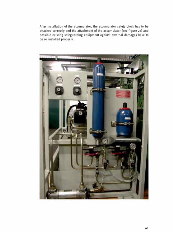
After installation of the accumulator, the accumulator safety block has to be attached correctly and the attachment of the accumulator (see figure 22) and possible existing safeguarding equipment against external damages have to be re-installed properly.
Figure 22: Hydraulic accumulator
42
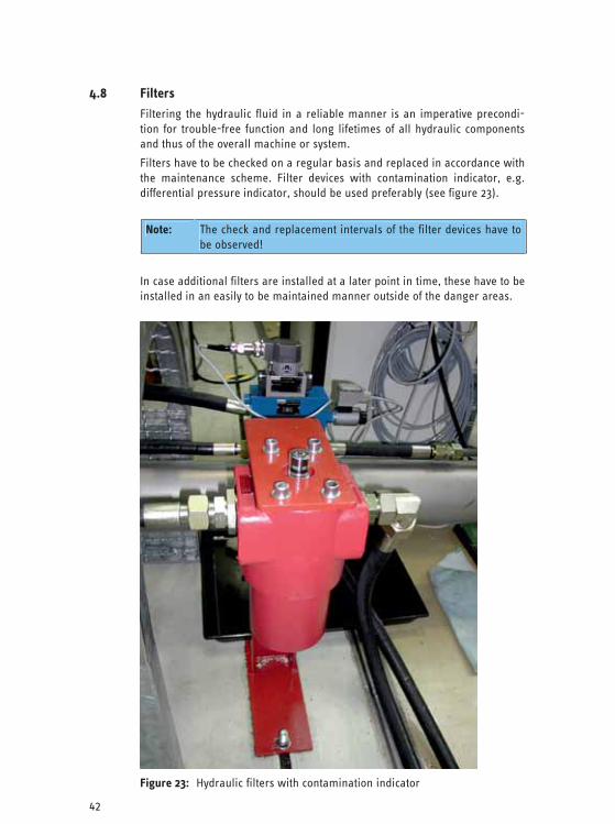
4.8 Filters
Filtering the hydraulic fluid in a reliable manner is an imperative precondi-tion for trouble-free function and long lifetimes of all hydraulic components and thus of the overall machine or system.
Filters have to be checked on a regular basis and replaced in accordance with the maintenance scheme. Filter devices with contamination indicator, e.g. differential pressure indicator, should be used preferably (see figure 23).
Note: The check and replacement intervals of the filter devices have to
be observed!
In case additional filters are installed at a later point in time, these have to be installed in an easily to be maintained manner outside of the danger areas.
Figure 23: Hydraulic filters with contamination indicator

43
5 Working on Machines and Systems
5.1 General
Basically, the manufacturer’s provisions in the operating instructions have to be observed.
Along with the basic general safety instructions for maintenance works and for handling hydraulic components (see section 4) the following section con-tains further notices for the safe hydraulic maintenance on stationary ma-chines and systems.
Figure 24: Hydraulic aggregate on stationary production facility

44
5.1.1 Reducing Hydraulic Energy
Before starting to work, the hydraulic energy in the system has to be reduced. Re-closing of the system has to be prevented. If individual hydraulic circuits of the hydraulic system are separated from the common pressure supply, it has to be checked if the correct connection has been disconnected.
Furthermore, the accumulators connected to the hydraulic system have to be disconnected from the system or depressurized (see figure 25). The depres-surization must not lead to new hazards, e.g. loosening of clamping devices. The pressure having been reduced completely has to be checked (see “five finger rule” in section 1.5).
Figure 25: Depressurized hydraulic accumulators with closed pressure lines
Despite the energy supply being switched off hydraulically elevated loads, e.g. machine parts, work platforms, hydraulic vertical axes, result in a sub-stantial pressure in parts of the hydraulic system. On more complex machines and systems this pressure can transfer to further parts of the system. Thus, elevated loads, e.g. material to be conveyed or machine parts, have to be lowered, secured using existing locks, or supported in a safe manner before starting the maintenance works.
After reduction of all pressures supplied into the hydraulic system, it is possi-ble that residual pressures still exist in trapped heads of liquids between valves and other parts. These have to be reduced as well, e.g. by operating the valves several times or in accordance with the manufacturer’s provisions.
45
After successful depressurization, screwed connections on hydraulic lines at first should be opened carefully and slowly. The screwed connections should be loosened further carefully as well, in order to realize possible hazards caused by the still existing pressure of the hydraulic fluid in time (slightly knocking on the screwed connection is helpful) and to take protective meas-ures. If pressure is still present the screwed connection must not be loosened further. The depressurization in the system has to be repeated and the effects of this procedure have to be re-checked.
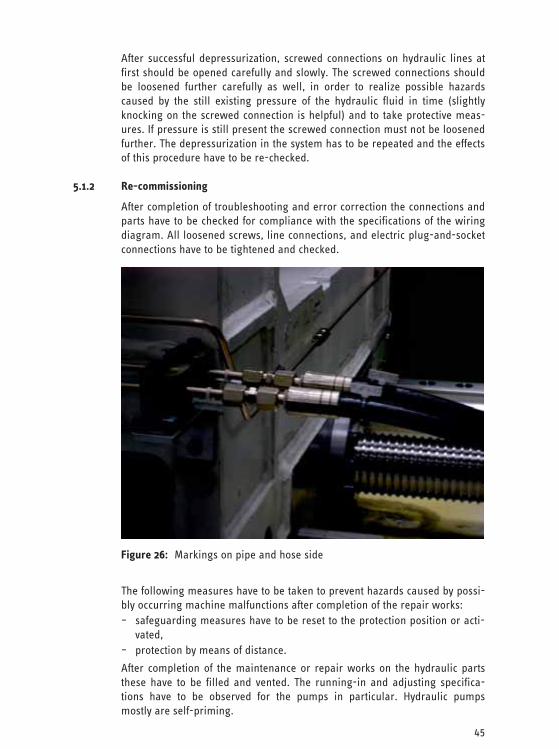
5.1.2 Re-commissioning
After completion of troubleshooting and error correction the connections and parts have to be checked for compliance with the specifications of the wiring diagram. All loosened screws, line connections, and electric plug-and-socket connections have to be tightened and checked.
Figure 26: Markings on pipe and hose side
The following measures have to be taken to prevent hazards caused by possi-bly occurring machine malfunctions after completion of the repair works: – safeguarding measures have to be reset to the protection position or acti-
vated, – protection by means of distance.
After completion of the maintenance or repair works on the hydraulic parts these have to be filled and vented. The running-in and adjusting specifica-tions have to be observed for the pumps in particular. Hydraulic pumps mostly are self-priming.
46
Adjustment works on the pressure relief valves must only be conducted by the manufacturer or in accordance with the manufacturer’s specifications, e.g. according to the pressure measurement sheets. It is imperative to adhere to the sequence of the procedure contained therein.
Incomplete venting procedures may lead to failures and hazards in machines and systems caused by suddenly starting movements. Venting the system completely prevents unforeseeable sudden movements of hydraulic cylinders and motors, e.g. stick slip.
After successful ventilation of the hydraulic system, all hydraulic functions have to be checked.
In doing so, the specifications regarding the safety have to be observed, e.g. system pressure, screenings. When testing the hydraulic functions it is impor-tant the keep sufficient distance as regards to reaching danger areas. It has to be ensured that neither the maintenance technician nor other persons stay below elevated loads or in danger areas.
Supports and safety measures for elevated loads must be removed only when the load is held safely by the hydraulic system again.
5.2 Working on Machine Tools
5.2.1 Clamping devices
Machine tools may have hydraulic clamping devices working in accordance with the closed circuit current principle. The clamping force is generated by spring force. In order to loosen the clamped parts, the spring force is com-pensated by means of an hydraulic cylinder in this case.
For this functional principle sudden pressure drops, e.g. due to hydraulic line failure, or a deadlock of the clamping system loosening suddenly on the basis of the spring force, can lead to pinch hazards for operator or maintenance technician.
5.2.2 Vertical Slides on Machine Tools
Machine tools may have hydraulically elevated vertical axes or other axes loaded by gravity that are held in their position by means of hydraulic brake and holding devices. These vertical slides have to be considered alike the ele-vated loads (see section 5.1.1).
5.3 Working on Hydraulic Presses
In accordance with the European Machine Directive, presses are classified as particularly dangerous machines. Thus, press manufacturers have to equip the machines with comprehensive safety technology. On the basis of this comprehensive safety technology, the maintenance technicians for hydraulic systems have to familiarize with the particularities of these machines before starting any maintenance works.

47
Figure 27: Complex clamping module of a transfer line
Before starting any maintenance works, the drive has to be switched off and an existing turn-off device has to be operated.
When working on hydraulic presses below elevated loads, e.g. upper die, the device [slide support] has to be brought into the protection position against retraction of the slide at first. Normally, such devices are installed on presses with a bolster plate depth of more than 800mm and a stroke height of more than 500mm. If the press is not equipped with such a device a support has to be used that is able to accept the forces present when the drive is switched off.
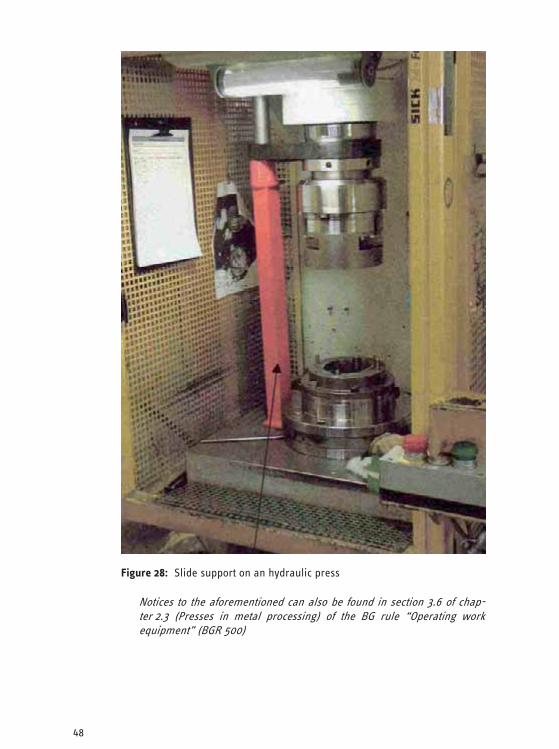
48
Figure 28: Slide support on an hydraulic press
Notices to the aforementioned can also be found in section 3.6 of chap-ter 2.3 (Presses in metal processing) of the BG rule “Operating work equipment” (BGR 500)
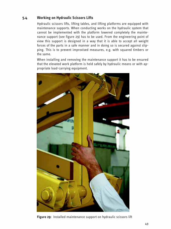
49
5.4 Working on Hydraulic Scissors Lifts
Hydraulic scissors lifts, lifting tables, and lifting platforms are equipped with maintenance supports. When conducting works on the hydraulic system that cannot be implemented with the platform lowered completely the mainte-nance support (see figure 29) has to be used. From the engineering point of view this support is designed in a way that it is able to accept all weight forces of the parts in a safe manner and in doing so is secured against slip-ping. This is to prevent improvised measures, e.g. with squared timbers or the same.
When installing and removing the maintenance support it has to be ensured that the elevated work platform is held safely by hydraulic means or with ap-propriate load-carrying equipment.
Figure 29: Installed maintenance support on hydraulic scissors lift
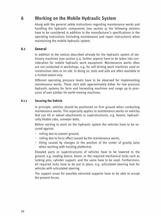
50
6 Working on the Mobile Hydraulic System Along with the general safety instructions regarding maintenance works and handling the hydraulic components (see section 4) the following sections have to be considered in addition to the manufacturer’s specifications in the operating instructions (including maintenance and repair instructions) when maintaining the mobile hydraulic system.
6.1 General
In addition to the notices described already for the hydraulic system of sta-tionary machines (see section 5.1), further aspects have to be taken into con-sideration for mobile hydraulic work equipment. Maintenance works often are not conducted in workshops, e.g. for self-driving work machines used on construction sites or on site. In doing so, tools and aids are often available to a limited extent only.
Different operating pressure levels have to be observed for implementing maintenance works. These start with approximately 60bar for low pressure hydraulic systems for farm and harvesting machines and range up to pres-sures of over 400bar for earth-moving machines.
6.1.1 Securing the Vehicle
In principle, vehicles should be positioned on firm ground when conducting maintenance works. This especially applies to maintenance works on vehicles that can tilt or swivel attachments or superstructures, e.g. booms, hydrauli-cally tiltable cabs, conveyor belts.
Before starting to work on the hydraulic system the vehicles have to be se-cured against:
– rolling due to uneven ground, – rolling due to force effect caused by the maintenance works, – tilting caused by changes to the position of the center of gravity (also
when working with hoisting platforms).
Elevated parts or superstructures of vehicles have to be lowered to the ground, e.g. loading device, boom, or the required mechanical locks such as locking pins, cylinder support, and the same have to be used. Furthermore, all required locks have to be put in place, e.g. articulated steering lock for vehicles with articulated steering.
The support areas for possibly extracted supports have to be able to accept the present forces.
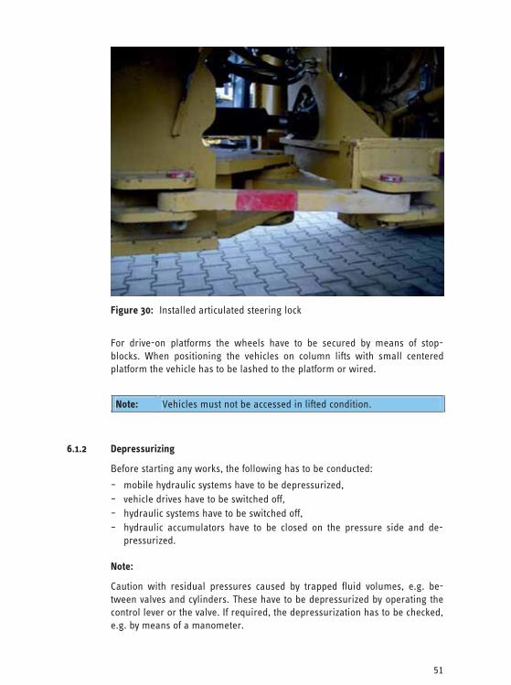
51
Figure 30: Installed articulated steering lock
For drive-on platforms the wheels have to be secured by means of stop-blocks. When positioning the vehicles on column lifts with small centered platform the vehicle has to be lashed to the platform or wired.
Note: Vehicles must not be accessed in lifted condition.
6.1.2 Depressurizing
Before starting any works, the following has to be conducted:
– mobile hydraulic systems have to be depressurized, – vehicle drives have to be switched off, – hydraulic systems have to be switched off, – hydraulic accumulators have to be closed on the pressure side and de-
pressurized.
Note:
Caution with residual pressures caused by trapped fluid volumes, e.g. be-tween valves and cylinders. These have to be depressurized by operating the control lever or the valve. If required, the depressurization has to be checked, e.g. by means of a manometer.
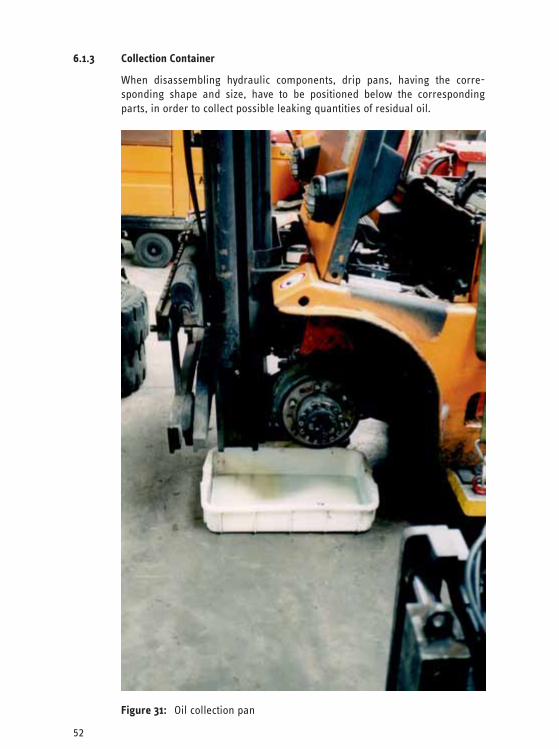
52
6.1.3 Collection Container
When disassembling hydraulic components, drip pans, having the corre-sponding shape and size, have to be positioned below the corresponding parts, in order to collect possible leaking quantities of residual oil.
Figure 31: Oil collection pan
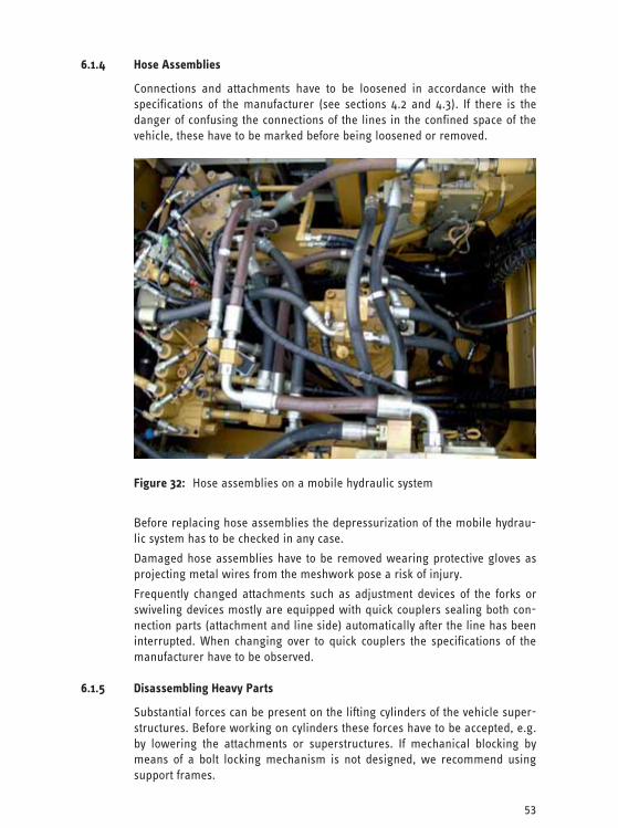
53
6.1.4 Hose Assemblies
Connections and attachments have to be loosened in accordance with the specifications of the manufacturer (see sections 4.2 and 4.3). If there is the danger of confusing the connections of the lines in the confined space of the vehicle, these have to be marked before being loosened or removed.
Figure 32: Hose assemblies on a mobile hydraulic system
Before replacing hose assemblies the depressurization of the mobile hydrau-lic system has to be checked in any case.
Damaged hose assemblies have to be removed wearing protective gloves as projecting metal wires from the meshwork pose a risk of injury.
Frequently changed attachments such as adjustment devices of the forks or swiveling devices mostly are equipped with quick couplers sealing both con-nection parts (attachment and line side) automatically after the line has been interrupted. When changing over to quick couplers the specifications of the manufacturer have to be observed.
6.1.5 Disassembling Heavy Parts
Substantial forces can be present on the lifting cylinders of the vehicle super-structures. Before working on cylinders these forces have to be accepted, e.g. by lowering the attachments or superstructures. If mechanical blocking by means of a bolt locking mechanism is not designed, we recommend using support frames.

54
Figure 33: Support frame when working on wheel-type loaders
Numerous hydraulic components are characterized by high dead loads and off-center position of the center of gravity, e.g. traction drives, main pumps, boom cylinders. Thus, replacing these components has to be conducted with the help of lifting gear attached to the designed attachment points.
6.1.6 Replacing the Hydraulic Fluid
Mobile suction devices used to empty the tank are suitable for replacing the hydraulic fluid. Replaced filters can drain with the help of a hopper device.
Mobile filling devices with integrated leakage protection/collection pan are particularly suitable for filling the system with new hydraulic oil (see sec-tion 2).
6.1.7 Fire Hazards
Hydraulic oil may ignite at hot surfaces, e.g. exhaust manifold, turbocharg-ers. Insulating materials have a wicking function when contaminated with hydraulic oil, which makes them easily inflammable.
Measures for reducing the fire hazard are:
– removing leaked hydraulic oil completely (see section 2.2) and wiping parts dry,
– renewing soaked insulation material, e.g. noise protection lining, – avoiding external ignition sources, e.g. cigarettes, – covering hot surfaces.
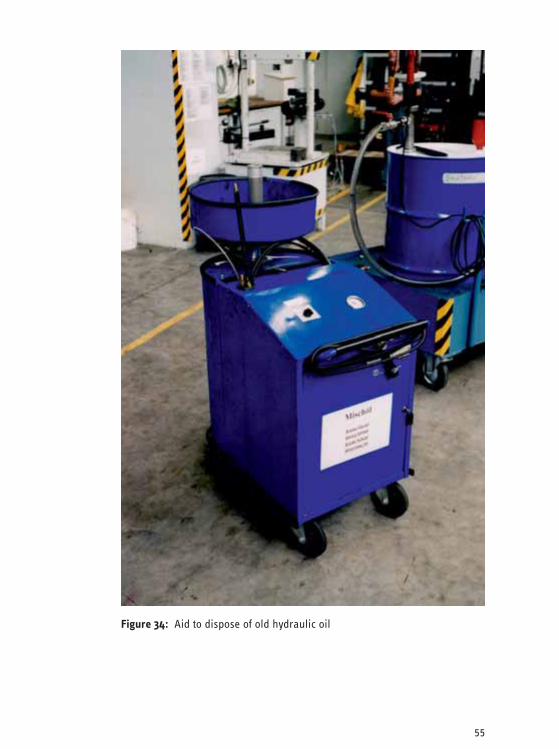
55
Figure 34: Aid to dispose of old hydraulic oil

56
6.1.8 Working while Drive is Running
Basically, repair works must only be implemented with the drive standing still. If works can only be conducted with the drive running, e.g. for testing and adjustment works, hazards have to be taken into account caused by:
– unprotected mechanic drives with rotating parts, – hot surfaces of parts, – noise.
The works must only be conducted by trained and experienced maintenance technicians. When conducting these works corresponding technical and per-sonal protection measures have to be taken, e.g. safety by means of distance, covers, hearing protection, and further personal protection equipment, if re-quired.
6.1.9 Re-commissioning
After completion of the maintenance works, including the ready-to-operate filling and venting of the hydraulic system, the drive and work functions have to be tested individually and if possible at low speeds and load-free. This should be implemented either behind screenings or from the safe distance.
The following procedure is recommended for testing the functionality of the hydraulic system:
1. checking all valve functions for correct sense of direction and shut-down function (neutral position),
2. executing larger travels of cylinders respectively swiveling areas of mo-tors.
While testing the functionality of the hydraulic system the machine operator has to observe that no persons are located in the danger area.
6.1.10 Spare Parts
Specifications or approvals of the manufacturer have to be complied with, e.g. regarding spare parts for hydraulic systems, hose assemblies, material specifications, hydraulic fluids, and the same.
Note: The operating instructions (including maintenance and repair instructions), as well as the spare parts list have to be carried along or kept at hand on site in order to implement maintenance works on mobile hydraulic systems.
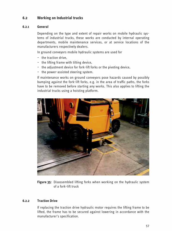
57
6.2 Working on Industrial trucks
6.2.1 General
Depending on the type and extent of repair works on mobile hydraulic sys-tems of industrial trucks, these works are conducted by internal operating departments, mobile maintenance services, or at service locations of the manufacturers respectively dealers.
In ground conveyors mobile hydraulic systems are used for
– the traction drive, – the lifting frame with tilting device, – the adjustment device for fork-lift forks or the pivoting device, – the power-assisted steering system.
If maintenance works on ground conveyors pose hazards caused by possibly bumping against the fork-lift forks, e.g. in the area of traffic paths, the forks have to be removed before starting any works. This also applies to lifting the industrial trucks using a hoisting platform.
Figure 35: Disassembled lifting forks when working on the hydraulic system of a fork-lift truck
6.2.2 Traction Drive
If replacing the traction drive hydraulic motor requires the lifting frame to be lifted, the frame has to be secured against lowering in accordance with the manufacturer’s specification.

58
6.2.3 Lifting Cylinder
The safe condition of the lifting frame is essential for the operational safety of the ground conveyor. Repairs should only be conducted by especially trained personnel, e.g. with the manufacturer, or by the customer service. The manu-facturer’s specifications have to be observed during all works on the lifting frame.
The lifting frame has to be lowered, supported, driven into a frame, or blocked mechanically before starting any works on lifting cylinders. Working on telescopable lifting frames, e.g. in duplex or triplex design, should always be implemented by the customer service.
When installing a new lifting cylinder it has to be observed that the hydraulic hose assemblies are inserted properly into the designed guiding/deflection pulleys.
On older ground conveyors with hose rollers at the side of the lifting frame it has to be observed that the hose assembly is subject to spring force on the roller side. When loosening the connection, the hose assembly has to be se-cured against moving, e.g. by means of a second person. In doing so, the hazard of being pulled-in or pinched has to be observed at the hose roller.
6.2.4 Tilting Cylinder
Before starting to work on the tilting cylinders the lifting frame has to be se-cured against moving due to its dead load in accordance with the manufac-turer’s specifications. This can be implemented for example by lashing the lifting gear in the rearmost position using the designed attachment points or on the driver protection roof.
The tilting cylinders have to be filled with hydraulic fluid before being in-stalled (see section 4.4).
Figure 36: Lashed lifting frame when working on tilting cylinders
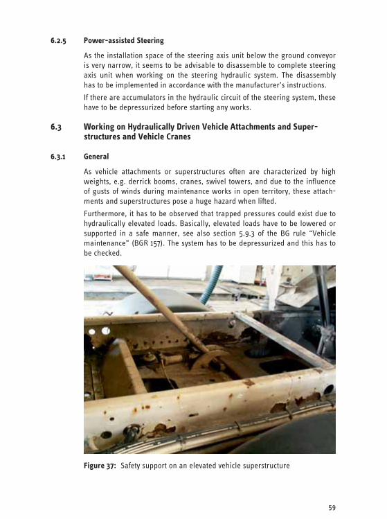
59
6.2.5 Power-assisted Steering
As the installation space of the steering axis unit below the ground conveyor is very narrow, it seems to be advisable to disassemble to complete steering axis unit when working on the steering hydraulic system. The disassembly has to be implemented in accordance with the manufacturer’s instructions.
If there are accumulators in the hydraulic circuit of the steering system, these have to be depressurized before starting any works.
6.3 Working on Hydraulically Driven Vehicle Attachments and Super-structures and Vehicle Cranes
6.3.1 General
As vehicle attachments or superstructures often are characterized by high weights, e.g. derrick booms, cranes, swivel towers, and due to the influence of gusts of winds during maintenance works in open territory, these attach-ments and superstructures pose a huge hazard when lifted.
Furthermore, it has to be observed that trapped pressures could exist due to hydraulically elevated loads. Basically, elevated loads have to be lowered or supported in a safe manner, see also section 5.9.3 of the BG rule “Vehicle maintenance” (BGR 157). The system has to be depressurized and this has to be checked.
Figure 37: Safety support on an elevated vehicle superstructure
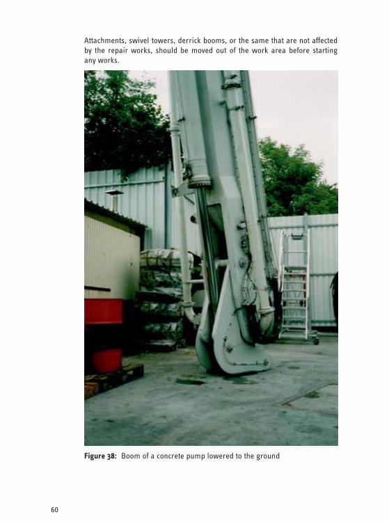
60
Attachments, swivel towers, derrick booms, or the same that are not affected by the repair works, should be moved out of the work area before starting any works.
Figure 38: Boom of a concrete pump lowered to the ground
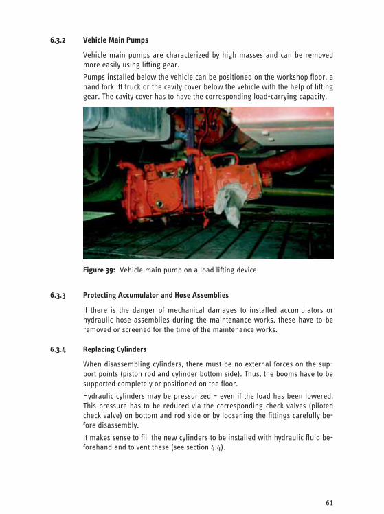
61
6.3.2 Vehicle Main Pumps
Vehicle main pumps are characterized by high masses and can be removed more easily using lifting gear.
Pumps installed below the vehicle can be positioned on the workshop floor, a hand forklift truck or the cavity cover below the vehicle with the help of lifting gear. The cavity cover has to have the corresponding load-carrying capacity.
Figure 39: Vehicle main pump on a load lifting device
6.3.3 Protecting Accumulator and Hose Assemblies
If there is the danger of mechanical damages to installed accumulators or hydraulic hose assemblies during the maintenance works, these have to be removed or screened for the time of the maintenance works.
6.3.4 Replacing Cylinders
When disassembling cylinders, there must be no external forces on the sup-port points (piston rod and cylinder bottom side). Thus, the booms have to be supported completely or positioned on the floor.
Hydraulic cylinders may be pressurized – even if the load has been lowered. This pressure has to be reduced via the corresponding check valves (piloted check valve) on bottom and rod side or by loosening the fittings carefully be-fore disassembly.
It makes sense to fill the new cylinders to be installed with hydraulic fluid be-forehand and to vent these (see section 4.4).
62
6.3.5 Checking the Hose-Assemblies
When conducting annual vehicle checks (according to § 57 of the accident prevention regulation “Vehicles” [BGV D29]) or when checking the attach-ments or superstructures the hydraulic hose assemblies have to be checked as well (see section 4.3.5).
6.4 Working on Earth-moving Equipment and Other Automotive Work Machines
6.4.1 General
The individual parts of the work equipment and the chassis of earth-moving machines, as well as other automobile work machines may be characterized by high dead loads. Along with present oil pressure, accumulators are used frequently posing a particular risk potential (see section 4.7).
Earth moving machines frequently are repaired, serviced and maintained in rough terrain or on construction sites.
Sudden position changes of the machine or its parts, as well as the risk of fal-ling down when being on higher parts of work machines while implementing maintenance works cause particular hazards (see section 6.4.3).
6.4.2 Securing Machines and Machine Parts Against Movement
Before starting any maintenance works, the machine has to be driven onto level territory with firm ground and has to be secured against rolling. The work equipment is to be lowered.
If the maintenance works cannot be implemented on level territory, works have to be implemented on the braking system, or if the machine has to be jacked up on one side, an additional safeguarding measure by means of stop-blocks is required.
If work machines are lifted for maintenance works, the machines have to be supported by means of bearing frames or with cross stacks consisting of boards or square timbers before starting any works. Works on lifted ma-chines or devices that are only held by the hydraulic pressure of the machine or the vehicle are inadmissible.
By lifting a work machine with articulated steering on one side or due to a loss of pressure in the hydraulic system the steering system could be acti-vated suddenly. In this, the machine may loose its stability and persons standing near the machine could be wedged. If works have to be imple-mented in the area of the articulated steering system or if machines having an articulated steering system have to be jacked up, the mechanical articu-lated steering lock (positive locking fixing device) has to be engaged first.
When working on hydraulic excavators the superstructure has to be secured against swiveling before starting any maintenance works.
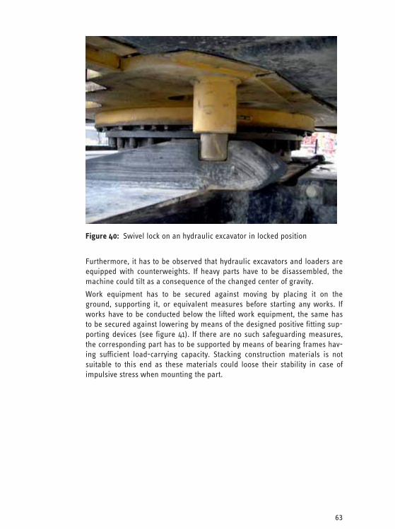
63
Figure 40: Swivel lock on an hydraulic excavator in locked position
Furthermore, it has to be observed that hydraulic excavators and loaders are equipped with counterweights. If heavy parts have to be disassembled, the machine could tilt as a consequence of the changed center of gravity.
Work equipment has to be secured against moving by placing it on the ground, supporting it, or equivalent measures before starting any works. If works have to be conducted below the lifted work equipment, the same has to be secured against lowering by means of the designed positive fitting sup-porting devices (see figure 41). If there are no such safeguarding measures, the corresponding part has to be supported by means of bearing frames hav-ing sufficient load-carrying capacity. Stacking construction materials is not suitable to this end as these materials could loose their stability in case of impulsive stress when mounting the part.

64
Figure 41: Supporting device in place on an earth-moving machine
6.4.3 High-level Places of Work
It has to be possible to reach platforms for maintenance and repair works in a safe manner. If there is the risk of falling down, appropriate safeguarding equipment has to be used. Hydraulic components must not be used as climb-ing aids or attachment point for safeguarding equipment against falling.
Parts of the work machine must only be used as place of work or access if the manufacturer has designed them to this end and if they are stable and skid-proof.

65
If mounting works on site are conducted with the help of other work ma-chines or ground conveyors, these have to be approved for these purposes and have to be equipped with an admissible device for accommodating per-sons, e.g. work platform; also see BG information “Work platforms on hy-draulic excavators and loaders” (BGI 872). Works must not be implemented from lifted work equipment, e.g. shovel or fork/pallet.
6.4.4 Depressurizing
Before starting to work the pressure in the hydraulic system has to be re-duced. This has to be implemented in accordance with the manufacturer’s specifications.
Normally, accumulators are used in the steering, braking or pre-control hy-draulic systems of working machines, as well as in the work hydraulic circuits of loaders/loading machines as vibration dampening system. These have to be depressurized on the fluid side before starting any works.
Note:
If the accumulator of the pre-control hydraulic system has been depressur-ized already the work equipment may only be lowered by means of a manual emergency lowering device by hand, e.g. via load holding valve on the boom of an hydraulic excavator.
Note: Before re-commissioning load holding valves have to be re-adjusted in accordance with the manufacturer’s specifications!
The hydraulic tank on work machines can be under overpressure. Before starting any works on the hydraulic system the tank has to be depressurized.
6.4.5 Disassembling Parts
It may be required to use lifting gear in order to implement mounting works on hydraulic components. On construction sites these works often are con-ducted with the help of other earth-moving machines. It has to be observed that the manufacturers designed and equipped these machines for lifting gear operation. The notices in the operating instructions have to be observed.
During the mounting works chain hoists may be of help allowing for position-ing the parts precisely.
Hydraulic cylinders have to be lifted by means of suitable lifting accessories, e.g. attached with lifting straps or round slings in two-stringed design. The extraction of the piston rod during the lifting procedure can be prevented by closing the connections using blind plugs after having disconnected the lines.
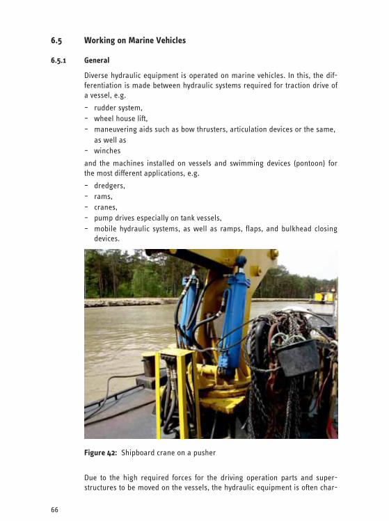
66
6.5 Working on Marine Vehicles
6.5.1 General
Diverse hydraulic equipment is operated on marine vehicles. In this, the dif-ferentiation is made between hydraulic systems required for traction drive of a vessel, e.g.
– rudder system, – wheel house lift, – maneuvering aids such as bow thrusters, articulation devices or the same, as well as – winches
and the machines installed on vessels and swimming devices (pontoon) for the most different applications, e.g.
– dredgers, – rams, – cranes, – pump drives especially on tank vessels, – mobile hydraulic systems, as well as ramps, flaps, and bulkhead closing
devices.
Figure 42: Shipboard crane on a pusher
Due to the high required forces for the driving operation parts and super-structures to be moved on the vessels, the hydraulic equipment is often char-

67
acterized by high dead loads. However, further particularities as described in sections 6.5.2 to 6.5.5 have to be observed additionally.
6.5.2 Position Change of the Vessel
Swimming vessels never stop moving. Due to pull and wave effects of passing vessels, wind and swell (even in coastal waters) even vessels positioned in ports are subject to slight lateral tilting movements by several angular de-grees. Loading and unloading freight vessels result in a constantly changing swimming position around the longitudinal and cross axes.
The vessel movements can lead to unintended movements of unsecured ves-sel and machine parts. Thus, anticipatory planning of maintenance works on vessels is required.
Note: All works have to be coordinated with the steerman.
6.5.3 Unsecured Hydraulic Drives on Vessels
For hydraulic systems of the driving operation, e.g. rudder systems, high re-quirements are posed regarding the availability and the operational safety of the systems. Within the sphere of action of these systems of the driving op-eration, safeguarding measures resulting in the rudder system being deacti-vated automatically are inadmissible from the point of view of traffic law. Technical protection measures such as separating protection devices cannot be implemented in all positions. This poses the risk of accessing work and traffic areas, in which hydraulic parts are installed in an unprotected manner and stripping protections and pipe and hose rupture protections frequently are missing. Due to the narrow installation situation and possible stumble positions there is a high risk of pinching and thus direct danger to life due to moving system parts.
6.5.4 Limited Installation Conditions
Due to the narrow installation situation in the hull and the metallic parts, in-terior walls, bulkheads, and doors on all sides most of the maintenance works are “Works in confined spaces”, which are subject to special require-ments regarding the electric equipment, see BG information “Working in confined spaces” (BGI 534).

68
Figure 43: Risks of pinching on a rudder system
6.5.5 Redundancy of Important Drive Operation Systems
On the basis of vessel security provisions rudder systems are designed re-dundantly, i.e. in double design, in order to provide for high reliability re-spectively availability. This is to maintain the maneuverability even if the sys-tem has failed.
In doing so, different principles are applied:
– two parallel identical system supplied by different energy sources with automatic switch-over,
– separately engaged emergency systems with limited continuous operation of the rudder system (emergency manual rudder, electric auxiliary pump),
– accumulators allowing for a limited number of rudder movements.
Works on these systems must only be implemented after consultation with the steerman! Before starting any works on the hydraulic system all relevant energy sources have to be turned off (see section 1.5). Even manual hydraulic rudder systems on small vessels and emergency manual pumps have to be secured against being used before starting any maintenance works.
69
7 Required Tests
7.1 General
Work equipment (machines) has to be checked due to the most different rea-sons. The regulations for the test result on the basis of the operational safety regulation.
In order to ensure proper installation and safe functionality of the work equipment these have to be checked before initial commissioning and after every installation at a new location. The test has to be arranged by the opera-tor of the work equipment (see also section 7.2).
Furthermore, work equipment is subject to damaging influences or wear and tear. In order to detect and remedy damages in a timely manner and to allow for safe operation the work equipment has to be checked at regular intervals. These tests have to be arranged by the operator as well (see also section 7.3).
7.2 Checking for Proper Installation and Safe Function
When checking “for proper installation and safe function”, criteria are as-sessed that relate to the installation respectively that can only be assessed on the completely installed machine.
Some of these test criteria can already be assessed during a “visual inspec-tion” in deactivated state, others require “functional testing” with activated energy supply.
An overview over the recommended test extent for a “visual inspection” (in connection with the hydraulic equipment) can be found in appendix 1 letter C.
An overview over the recommended test extent for a “functional test” (in con-nection with the hydraulic equipment) can be found in appendix 1 letter D.
7.3 Checking for Safe Provision and Use
Testing for safe provision and use assesses criteria subject to damaging influ-ences. However, this test has to be conducted after accidents, modifications (remodeling) to the machine, longer terms of non-use, as well as after repair measures as a result of damages (collision, acts of God).
A detailed overview over the recommended test extent for “safe provision and use” (in connection with the hydraulic equipment) can be found in appendix letter E.
7.4 Legal Bases for the Tests
The legal provisions for testing work equipment, e.g. machines, systems and the same, can be found in the operational safety regulations.
The operator of the work equipment has to specify test lists, as well as type and extent of the tests for his individual application conditions within the framework of a risk assessment and has to implement the tests accordingly.
70
Legal provisions and recommendations of the manufacturer have to be ob-served.
For this, technical rules for operational safety TRBS 1201 are being prepared that contain some examples. The test provisions of previous BG accident pre-vention provisions and safety rules still can be used to support the specifica-tion of test extents and test intervals.
The tests must only be implemented by authorized persons instructed by the employer. An authorized person in the meaning of the operational safety regulation is a person that, on the basis of the vocational training, the profes-sional experience, and the contemporary professional activity, has the exper-tise for testing work equipment, see technical rules for operational safety TRBS 1203 “Authorized persons – general part”.
The rest results have to be documented and maintained at least until the next test.
8 First Aid The first aid measures at the accident site often are decisive for the following course of the healing procedure of an injury or even for saving the employee. In accordance with the accident prevention regulation “Basic principles of prevention” (BGV A1) the required number of trained first aiders has to be present in any case. The training is conducted by authorities approved by the institutions for statutory accident insurance and prevention. Furthermore, the employees have to be trained regarding the behavior in case of accidents at least once a year.
For the necessary help measures being able to be performed quickly and immediately the “reporting chain” has to be specified in a clear manner.
– Who calls for help? – Where can help be called from (location telephone, reporting authority)? – Which help is called (first aider, corporate reporting authority, public res-
cue service)?
This is particularly problematic and thus important for maintenance works situated at a larger distance to other work places.
In case of an accident an emergency call to the corporate emergency author-ity or the rescue coordination center (for accidents in Germany call 112) has to be implemented as follows:
– Where did it happen?
– What happened?
– How many injured/victims?
– Which type of injuries/illnesses?
– Wait for queries!
Working alone should be avoided in any case.

71
In areas where implementing first aid measures is not possible or only to a limited extent provisions for rescuing possible injured have to be ensured.
Places equipped with first aid kits or flushing devices have to be known and marked.
The hazards occurred especially when handling hydraulic fluids, as well as the corresponding first aid measures are:
Hazard Measure
Subcutaneous intrusion (injection) of high pressure hydraulic fluids
Consult doctor immediately; very important: inform doctor about course of acci-dent (oil injection), otherwise small wounds could be overlooked or treated improperly!
Hydraulic fluid in the eyes
Flush eyes at least 15 minutes with mild water (eye flushing device or clean water), contact doctor.
Swallowed hydraulic fluids Do not provoke vomiting, consult doctor immediately.
Burns due to hot hydraulic fluid Cool with mild water at least for 10 minutes, cover wound in sterile manner (i.e. with aseptic, non-adhesive dressing or material for burns), contact doctor.
Table: Measures in case of accidents with hydraulic fluids
The rescue service/emergency doctor has to be informed immediately on the type of hydraulic fluid. The current safety data sheet or the operating instruc-tions have to be held ready.

72
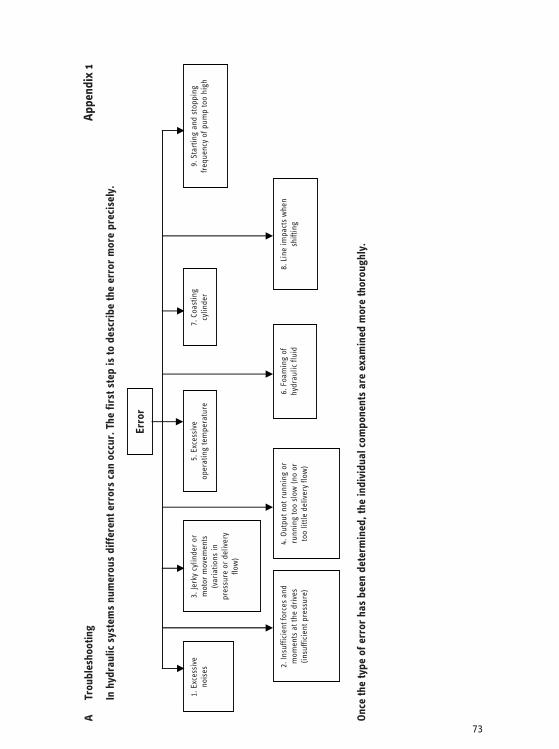
73
A Tr
oubl
esho
otin
gAp
pend
ix 1
In h
ydra
ulic
sys
tem
s nu
mer
ous
diff
eren
t err
ors
can
occu
r. T
he fi
rst s
tep
is to
des
crib
e th
e er
ror
mor
e pr
ecis
ely.
Once
the
type
of e
rror
has
bee
n de
term
ined
, the
indi
vidu
al c
ompo
nent
s ar
e ex
amin
ed m
ore
thor
ough
ly.
1. E
xces
sive
no
ises
3.
Jerk
y cy
linde
r or
m
otor
mov
emen
ts
(var
iatio
ns in
pr
essu
re o
r de
liver
y flo
w)
5. E
xces
sive
op
erat
ing
tem
pera
ture
7.
Coa
stin
g cy
linde
r 9.
Sta
rtin
g an
d st
oppi
ng
freq
uenc
y of
pum
p to
o hi
gh
2. In
suffi
cien
t for
ces
and
mom
ents
at t
he d
rive
s (in
suffi
cien
t pre
ssur
e)
4. O
utpu
t not
run
ning
or
runn
ing
too
slow
(no
or
too
little
del
iver
y flo
w)
6. F
oam
ing
of
hydr
aulic
flui
d 8.
Lin
e im
pact
s w
hen
shift
ing
Erro
r

74
1. E
xces
sive
noi
ses
1. C
lutc
h al
igne
d im
prop
erly
2.
Clu
tch
loos
e 3.
Clu
tch
faul
ty
4. A
ttach
men
t of
mot
or o
r pu
mp
loos
e 5.
Oth
er tr
ansm
issi
on
(v-b
elt,
toot
h be
lt)
faul
ty
6. P
ump
or m
otor
fa
ulty
7.
Wro
ng d
irec
tion
of
rota
tion
8. N
o no
ise-
optim
ized
de
sign
(sho
ck
mou
nt)
Mec
h. D
rive
par
t
1. E
xces
sive
pum
p sp
eed
2.
Pum
p m
ax p
ress
ure
exce
eded
3.
Sup
ply
pum
p fa
ulty
4.
Sha
ft se
al o
r se
als
on
suct
ion
side
faul
ty
5. P
ump
faul
ty
6. P
ress
ure
and
retu
rn
conn
ecte
d im
prop
erly
7.
vib
ratin
g co
ntro
ller
syst
em
8. N
o no
ise-
optim
ized
de
sign
(sho
ck m
ount
)
1. P
ipe
atta
chm
ent
mis
sing
or
loos
e 2.
Im
prop
er r
outin
g 3.
Cro
ss s
ectio
ns to
o sm
all
4. S
yste
m v
ente
d in
com
plet
ely
5. R
etur
n en
ds a
bove
flu
id le
vel
6. R
etur
n fil
ter
clog
ged
1. V
alve
vib
rate
s an
d st
imul
ates
oth
er
cont
rolle
rs to
vi-
brat
e 2.
Flo
w n
oise
s 3.
Vib
ratin
g co
ntro
l-le
r sy
stem
1. S
uctio
n di
fficu
lties
as
a. F
luid
leve
l too
low
b.
Vis
cosi
ty to
o hi
gh
(tem
pera
ture
low
) 2.
Flu
id c
onta
min
ated
an
d th
us d
evic
es
dam
aged
and
clo
gged
3.
Flu
id fo
amed
Pum
pRe
turn
line
Flow
-con
trol
val
ve
Hydr
aulic
flui
d
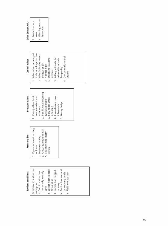
75
Suct
ions
con
ditio
ns
Resi
stan
ce in
suc
tion
line
too
high
as
1. C
ock
in s
uctio
n lin
e no
t or
only
par
tially
op
en
2. S
uctio
n fil
ter
clog
ged
or to
o sm
all
3. S
uctio
n lin
e cl
ogge
d or
leak
y 4.
Suc
tion
line
too
smal
l or
too
man
y be
nds
5. F
luid
leve
l too
low
Pres
sure
line
1. P
ipe
atta
chm
ent m
issi
ng
or lo
ose
2. I
mpr
oper
rou
ting
3. C
ross
sec
tions
too
smal
l 4.
Sys
tem
ven
ted
inco
m-
plet
ely
Pres
sure
val
ves
1. V
alve
judd
ers
due
to
cont
amin
ated
/ wor
n va
lve
seat
2.
Ins
uffic
ient
dam
peni
ng
(uns
uita
ble
type
) 3.
Flo
w n
oise
s w
hen
actu
atin
g 4.
Cha
ract
eris
tic c
urve
in
favo
rabl
e 5.
Wro
ng d
esig
n
Cont
rol v
alve
s
1. V
alve
judd
ers
as m
agne
t fa
ulty
or
volta
ge to
o lo
w
2. V
alve
faul
ty d
ue to
wea
r an
d te
ar o
r di
rt
3. F
low
too
high
4.
Var
iatio
ns in
con
trol
pr
essu
re
5. S
ettin
g no
t mad
e fo
r va
lves
with
set
tabl
e da
mpe
ning
6.
Che
ck e
lect
ric
cont
rol
syst
em
Driv
e (m
otor
, cyl
.)
1. C
onta
ct s
urfa
ce
wea
r 2.
Vib
ratin
g co
ntro
l-le
r sy
stem
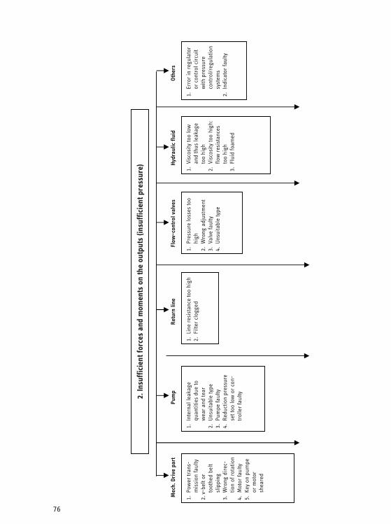
76
2. In
suff
icie
nt fo
rces
and
mom
ents
on
the
outp
uts
(insu
ffic
ient
pre
ssur
e)
1. P
ower
tran
s-m
issi
on fa
ulty
2.
v-b
elt o
r to
othe
d be
lt sl
ippi
ng
3. W
rong
dir
ec-
tion
of r
otat
ion
4. M
otor
faul
ty
5. K
ey o
n pu
mpe
or
mot
or
shea
red
Mec
h. D
rive
par
t
1. I
nter
nal l
eaka
ge
quan
titie
s du
e to
w
ear
and
tear
2.
Uns
uita
ble
type
3.
Pum
pe fa
ulty
4.
Red
uctio
n pr
essu
re
set t
oo lo
w o
r co
n-tr
olle
r fa
ulty
Pum
p
1. L
ine
resi
stan
ce to
o hi
gh
2. F
ilter
clo
gged
Retu
rn li
ne
1. P
ress
ure
loss
es to
o hi
gh
2. W
rong
adj
ustm
ent
3. V
alve
faul
ty
4. U
nsui
tabl
e ty
pe
Flow
-con
trol
val
ves
1. V
isco
sity
too
low
an
d th
us le
akag
e to
o hi
gh
2. V
isco
sity
too
high
: flo
w r
esis
tanc
es
too
high
3.
Flu
id fo
amed
Hydr
aulic
flui
d
1. E
rror
in r
egul
ator
or
con
trol
cir
cuit
with
pre
ssur
e co
ntro
l/reg
ulat
ion
syst
ems
2. I
ndic
ator
faul
ty
Othe
rs

77
Suct
ion
cond
ition
sPr
essu
re li
ne
1. L
eaka
ges
2. L
ine
resi
stan
ce to
o hi
gh
3. P
ress
ure
filte
r cl
ogge
d
Pres
sure
val
ves
1. O
pera
ting
pres
-su
re s
et to
o lo
w
2. I
nter
nal l
eak
due
to w
ear
and
tear
3.
Val
ve s
eat c
on-
tam
inat
ed o
r da
mag
ed
4. S
prin
g br
oken
5.
Uns
uita
ble
type
(S
ettin
g ra
nge
too
low
)
Cont
rol v
alve
s
1. W
rong
sw
itchi
ng
posi
tion
(e.g
. pre
s-su
re-l
ess
flow
doe
s no
t sw
itch
off)
2. M
agne
t fau
lty
3. I
nter
nal l
eak
due
to
wea
r an
d te
ar
4. F
low
res
ista
nce
too
high
5.
Gat
e st
uck
Driv
e (m
otor
, cyl
.)
1. I
nter
nal l
eaka
ge (e
.g.
wor
n cy
linde
r sl
eeve
) 2.
Con
tact
sur
face
wea
r an
d te
ar
3. I
nter
nal f
rict
ion
too
high
(in
effic
ient
)
Resi
stan
ce in
suc
tion
line
too
high
as
1. C
ock
in s
uctio
n lin
e no
t or
only
par
tially
op
en
2. S
uctio
n fil
ter
clog
ged
or to
o sm
all
3. S
uctio
n lin
e cl
ogge
d or
leak
y 4.
Suc
tion
line
too
smal
l or
too
man
y be
nds
5. F
luid
leve
l too
low
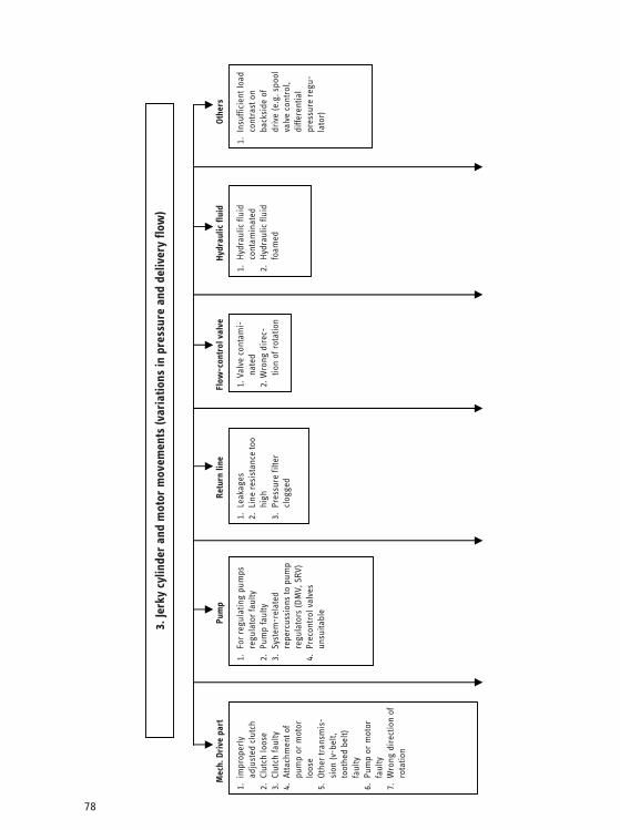
78
3. Je
rky
cylin
der
and
mot
or m
ovem
ents
(var
iatio
ns in
pre
ssur
e an
d de
liver
y flo
w)
1. F
or r
egul
atin
g pu
mps
re
gula
tor
faul
ty
2. P
ump
faul
ty
3. S
yste
m-r
elat
ed
repe
rcus
sion
s to
pum
p re
gula
tors
(DM
V, S
RV)
4. P
reco
ntro
l val
ves
unsu
itabl
e
1. V
alve
con
tam
i-na
ted
2. W
rong
dir
ec-
tion
of r
otat
ion
1. H
ydra
ulic
flui
d co
ntam
inat
ed
2. H
ydra
ulic
flui
d fo
amed
1. I
nsuf
ficie
nt lo
ad
cont
rast
on
back
side
of
driv
e (e
.g. s
pool
va
lve
cont
rol,
diffe
rent
ial
pres
sure
reg
u-la
tor)
Othe
rs
1. i
mpr
oper
ly
adju
sted
clu
tch
2. C
lutc
h lo
ose
3. C
lutc
h fa
ulty
4.
Atta
chm
ent o
f pu
mp
or m
otor
lo
ose
5. O
ther
tran
smis
-si
on (v
-bel
t, to
othe
d be
lt)
faul
ty
6. P
ump
or m
otor
fa
ulty
7.
Wro
ng d
irec
tion
of
rota
tion
1. L
eaka
ges
2. L
ine
resi
stan
ce to
o hi
gh
3. P
ress
ure
filte
r cl
ogge
d
Mec
h. D
rive
par
t Pu
mp
Retu
rn li
ne
Flow
-con
trol
val
ve
Hydr
aulic
flui
d

79
Suct
ion
cond
ition
s Pr
essu
re li
ne
1. S
yste
m v
ente
d in
com
plet
ely
Pres
sure
val
ves
1. V
alve
judd
ers
due
to
cont
amin
ated
/ wor
n va
lve
seat
2.
Ins
uffic
ient
dam
peni
ng
(uns
uita
ble
type
) 3.
Und
ampe
ned
cont
rol
line
too
long
4.
Uns
uita
ble
cont
rol
valv
e
Cont
rol v
alve
s Dr
ive
(mot
or, c
yl.)
1. S
tick
slip
effe
ct a
s fr
ictio
n of
cy
linde
r sl
eeve
s to
o hi
gh
2. F
alle
n be
low
the
limit
spee
d of
hyd
ro m
otor
Resi
stan
ce in
suc
tion
line
too
high
as
1. C
ock
in s
uctio
n lin
e no
t or
only
pa
rtia
lly o
pen
2. S
uctio
n fil
ter
clog
ged
or to
o sm
all
3. S
uctio
n lin
e cl
ogge
d or
leak
y 4.
Suc
tion
line
too
smal
l or
too
man
y be
nds
5. F
luid
leve
l too
low
1. V
alve
judd
ers
as
mag
net f
aulty
or
volt-
age
too
low
2.
Val
ve fa
ulty
due
to
wea
r an
d te
ar o
r di
rt
3. F
low
too
high
4.
Var
iatio
ns in
con
trol
pr
essu
re
5. S
ettin
g no
t mad
e fo
r va
lves
with
set
tabl
e da
mpe
ning
6.
Che
ck e
lect
ric
cont
rol
syst
em
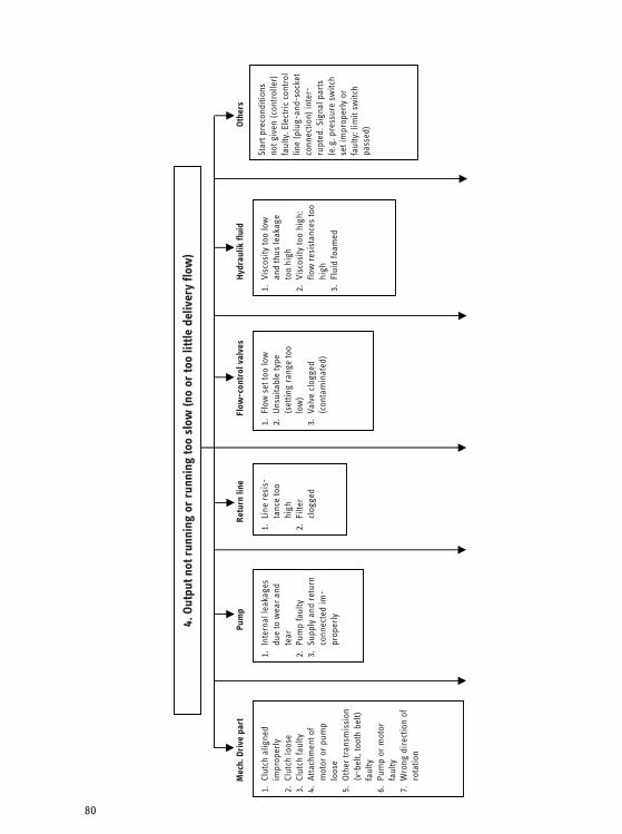
80
1. C
lutc
h al
igne
d im
prop
erly
2.
Clu
tch
loos
e 3.
Clu
tch
faul
ty
4. A
ttach
men
t of
mot
or o
r pu
mp
loos
e 5.
Oth
er tr
ansm
issi
on
(v-b
elt,
toot
h be
lt)
faul
ty
6. P
ump
or m
otor
fa
ulty
7.
Wro
ng d
irec
tion
of
rota
tion
Mec
h. D
rive
par
t
1. I
nter
nal l
eaka
ges
due
to w
ear
and
tear
2.
Pum
p fa
ulty
3.
Sup
ply
and
retu
rn
conn
ecte
d im
-pr
oper
ly
1. L
ine
resi
s-ta
nce
too
high
2.
Filt
er
clog
ged
Re
turn
line
1. F
low
set
too
low
2.
Uns
uita
ble
type
(s
ettin
g ra
nge
too
low
) 3.
Val
ve c
logg
ed
(con
tam
inat
ed)
Flow
-con
trol
val
ves
1. V
isco
sity
too
low
an
d th
us le
akag
e to
o hi
gh
2. V
isco
sity
too
high
: flo
w r
esis
tanc
es to
o hi
gh
3. F
luid
foam
ed
Hydr
aulik
flui
d
Star
t pre
cond
ition
s no
t giv
en (c
ontr
olle
r)
faul
ty. E
lect
ric
cont
rol
line
(plu
g-an
d-so
cket
co
nnec
tion)
inte
r-ru
pted
. Sig
nal p
arts
(e
.g. p
ress
ure
switc
h se
t im
prop
erly
or
faul
ty: l
imit
switc
h pa
ssed
) Othe
rs
4. O
utpu
t not
run
ning
or
runn
ing
too
slow
(no
or to
o lit
tle d
eliv
ery
flow
)
Pum
p
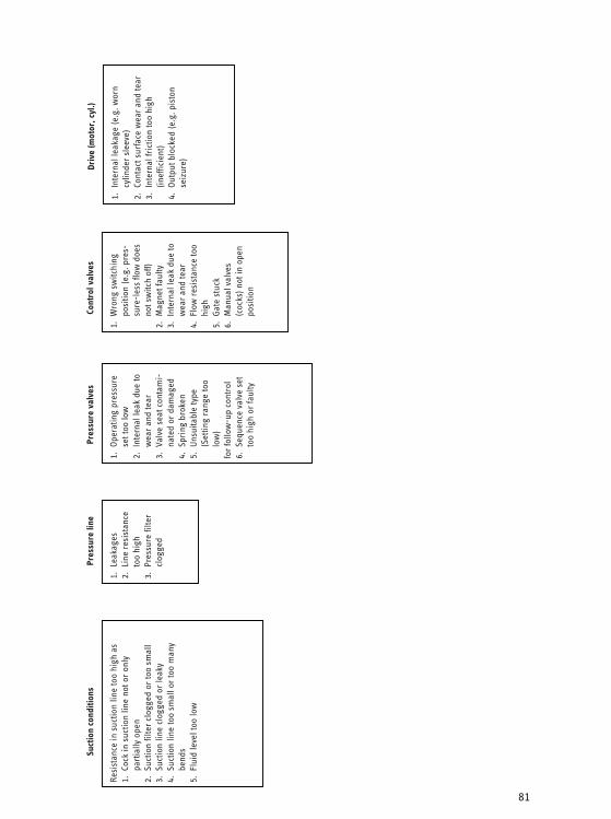
81
Suct
ion
cond
ition
s
Resi
stan
ce in
suc
tion
line
too
high
as
1. C
ock
in s
uctio
n lin
e no
t or
only
pa
rtia
lly o
pen
2. S
uctio
n fil
ter
clog
ged
or to
o sm
all
3. S
uctio
n lin
e cl
ogge
d or
leak
y 4.
Suc
tion
line
too
smal
l or
too
man
y be
nds
5. F
luid
leve
l too
low
Pres
sure
line
1. L
eaka
ges
2. L
ine
resi
stan
ce
too
high
3.
Pre
ssur
e fil
ter
clog
ged
Pres
sure
val
ves
1. O
pera
ting
pres
sure
se
t too
low
2.
Int
erna
l lea
k du
e to
w
ear
and
tear
3.
Val
ve s
eat c
onta
mi-
nate
d or
dam
aged
4.
Spr
ing
brok
en
5. U
nsui
tabl
e ty
pe
(Set
ting
rang
e to
o lo
w)
for
follo
w-u
p co
ntro
l 6.
Seq
uenc
e va
lve
set
too
high
or
faul
ty
Cont
rol v
alve
s
1. W
rong
sw
itchi
ng
posi
tion
(e.g
. pre
s-su
re-l
ess
flow
doe
s no
t sw
itch
off)
2. M
agne
t fau
lty
3. I
nter
nal l
eak
due
to
wea
r an
d te
ar
4. F
low
res
ista
nce
too
high
5.
Gat
e st
uck
6. M
anua
l val
ves
(coc
ks) n
ot in
ope
n po
sitio
n
Driv
e (m
otor
, cyl
.)
1. I
nter
nal l
eaka
ge (e
.g. w
orn
cylin
der
slee
ve)
2. C
onta
ct s
urfa
ce w
ear
and
tear
3.
Int
erna
l fri
ctio
n to
o hi
gh
(inef
ficie
nt)
4. O
utpu
t blo
cked
(e.g
. pis
ton
seiz
ure)
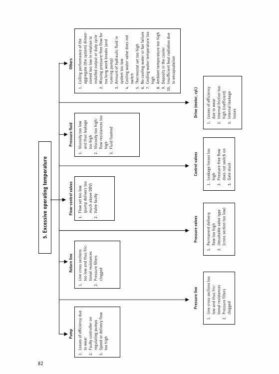
82
Pum
p Re
turn
line
Fl
ow-c
ontr
ol v
alve
sPr
essu
re fl
uid
Othe
rs
5. E
xces
sive
ope
ratin
g te
mpe
ratu
re
1. L
osse
s of
effi
cien
cy d
ue
to w
ear
2. F
aulty
con
trol
ler
on
regu
latin
g pu
mps
3.
Spe
ed o
r de
liver
y flo
w
too
high
1. L
ine
cros
s se
ctio
ns
too
low
and
thus
fric
-tio
nal r
esis
tanc
es
2. P
ress
ure
filte
rs
clog
ged
1. F
low
set
too
low
(p
ump
deliv
ers
too
muc
h ab
ove
DBV)
2.
Val
ve fa
ulty
1. V
isco
sity
too
low
an
d th
us le
akag
e to
o hi
gh
2. V
isco
sity
too
high
: flo
w r
esis
tanc
es to
o hi
gh
3. F
luid
foam
ed
1.
Colli
ng p
erfo
rman
ce o
f the
ag
greg
ate
(the
syst
em) d
imen
-si
oned
too
low
in r
elat
ion
to
inst
alle
d ou
tput
or
duty
cyc
le
2.
Mis
sing
pre
ssur
e-fr
ee fl
ow fo
r to
o lo
ng w
ork
brea
ks (a
nd
runn
ing
pum
p)
3.
Amou
nt o
f hyd
raul
ic fl
uid
in
syst
em to
o lo
w
4.
Cool
ing
wat
er v
alve
doe
s no
t sw
itch
5.
Ther
mos
tat s
et to
o hi
gh
6.
No
cool
ing
wat
er o
r fa
n fa
ilure
7.
Cool
ing
wat
er te
mpe
ratu
re to
o hi
gh
8.
Ambi
ent t
empe
ratu
re to
o hi
gh
9.
Depo
sits
in th
e co
oler
10
. In
suffi
cien
t hea
t rad
iatio
n du
e to
enc
apsu
latio
n
Driv
e (m
otor
, cyl
.)
1. L
osse
s of
effi
cien
cy
due
to w
ear
2. I
nter
nal f
rict
ion
too
high
(ine
ffici
ent)
3. I
nter
nal l
eaka
ge
loss
es
Cont
rol v
alve
s
1. L
eaka
ge lo
sses
too
high
2.
Pre
ssur
e-fr
ee fl
ow
does
not
sw
itch
on
3. G
ate
stuc
k
Pres
sure
val
ves
1. P
erm
anen
t del
iver
y flo
w to
o hi
gh
2. U
nsui
tabl
e va
lve
type
(c
ross
sec
tion
too
low
)
Pres
sure
live
1. L
ine
cros
s se
ctio
ns to
o lo
w a
nd th
us fr
ic-
tiona
l res
ista
nces
2.
Pre
ssur
e fil
ters
cl
ogge
d
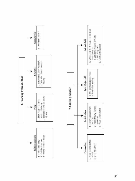
83
6. F
oam
ing
hydr
aulic
flui
d
Suct
iion
cond
ition
s
1. S
uctio
n lin
e le
aky
2.
Flu
id le
vel t
oo lo
w
3. W
rong
con
tain
er d
esig
n
1. S
haft
seal
s or
sea
ls o
n su
ctio
n si
de fa
ulty
2.
Lea
kage
oil
line
not b
elow
oi
l lev
el
Pum
p
1. R
etur
n en
ds a
bove
flui
d le
vel
2. S
wir
l effe
ct d
ue to
impr
oper
ro
utin
g
Retu
rn li
ne
1. U
nsui
tabl
e fa
bric
at
Hydr
aulic
flui
d
7. C
oast
ing
cylin
der
Pres
sure
line
1. H
ose
asse
mbl
ies
too
elas
tic
2. L
ines
not
ven
ted
1. S
witc
hing
adj
ustm
ent
too
slow
2.
Mag
net f
aulty
Lea
kage
qu
antit
ies
3. V
alve
con
tam
inat
ed
Cont
rol v
alve
s
1. I
nter
nal l
eaka
ge q
uant
ities
2.
Ins
uffic
ient
ven
ting
Driv
e (M
otor
, cyl
.)
1. U
nloc
kabl
e ch
eck
valv
e do
es n
ot c
lose
im
med
iate
ly a
s a.
Sea
t con
tam
inat
ed o
r fa
ulty
b.
Sw
itchi
ng e
rror
2.
Lim
it sw
itch
pass
ed
Hydr
aulic
flui
d

84
8. L
ine
impa
cts
whe
n sw
itchi
ng
Pres
sure
line
1. P
ipe
atta
chm
ent m
issi
ng o
r lo
ose
2. I
mpr
oper
rou
ting
3. C
ross
sec
tions
too
smal
l 4.
Sys
tem
ven
ted
inco
mpl
etel
y 5.
Sto
rage
vol
ume
of li
ne s
yste
m
too
high
1. S
witc
hing
too
quic
k 2.
Thr
ottle
s or
ori
fices
dam
-ag
ed Pr
essu
re v
alve
s
1. H
ydra
ulic
flui
d fo
amed
Hydr
aulic
flui
d
1.
For
accu
mul
ator
s m
issi
ng th
rot-
tles
in fr
ont o
f sw
itchi
ng v
alve
s
Othe
rs
Line
s lo
ose
Retu
rn li
ne
1. S
witc
hing
tim
e ad
just
men
t too
fa
st
2. U
nsui
tabl
e ty
pe (o
peni
ng c
ross
se
ctio
n ch
ange
d to
o fa
st)
Cont
rol v
alve
s
1. M
asse
s an
d fo
rces
too
high
2.
No
dam
peni
ng
Driv
e (m
otor
, cyl
.)
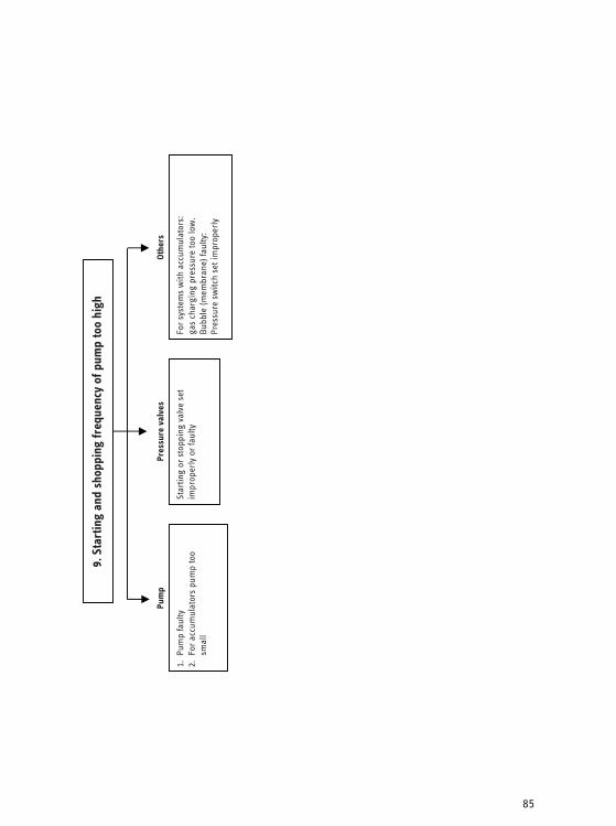
85
9. S
tart
ing
and
shop
ping
freq
uenc
y of
pum
p to
o hi
gh
Pum
p
1. P
ump
faul
ty
2. F
or a
ccum
ulat
ors
pum
p to
o sm
all
Star
ting
or s
topp
ing
valv
e se
t im
prop
erly
or
faul
ty
Pres
sure
val
ves
For
syst
ems
with
acc
umul
ator
s:
gas
char
ging
pre
ssur
e to
o lo
w.
Bubb
le (m
embr
ane)
faul
ty:
Pres
sure
sw
itch
set i
mpr
oper
ly
Othe
rs
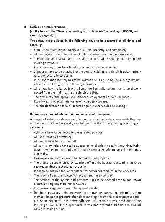
86
B Notices on maintenance (on the basis of the “General operating instructions 0/1” according to BOSCH, ver-sion 1.0, pages 63ff.)
The safety notices listed in the following have to be observed at all times and carefully.
– Conduct all maintenance works in due time, properly, and completely. – All employees have to be informed before starting any maintenance works. – The maintenance area has to be secured in a wide-ranging manner before
starting any works. – Corresponding signs have to inform about maintenance works. – Signposts have to be attached to the control cabinet, the circuit breaker, actua-
tors, and access in particular. – If the hydraulic assembly has to be switched off it has to be secured against un-
intended re-closing by the following measures: – All drives have to be switched off and the hydraulic system has to be discon-
nected from the mains using the circuit breaker. – The pressure of the hydraulic assembly or component has to be reduced. – Possibly existing accumulators have to be depressurized. – The circuit breaker has to be secured against unscheduled re-closing.
Before every manual intervention on the hydraulic component:
All required details on depressurization and on the hydraulic components that are not depressurized automatically can be found in the corresponding operating in-structions.
– Cylinders have to be moved to the safe stop position. – All loads have to be lowered. – All pumps have to be turned off. – All vertical cylinders have to be supported mechanically against lowering. Main-
tenance works on lifted units must not be conducted without securing the units externally.
– Existing accumulators have to be depressurized properly. – The pressure supply has to be switched off and the hydraulic assembly has to be
secured against unscheduled re-closing. – It has to be ensured that only authorized personnel remains in the work area. – The required personal protection equipment has to be used. – The sections of the system and pressure lines to be opened have to cool down
before starting any maintenance works. – Pressurized segments have to be opened slowly. – Due to check valves in the pressure lines above the pumps, the hydraulic system
may still be under pressure after disconnecting it from the proper pressure sup-ply. Some segments, e.g. servo cylinders, still remain pressurized due to the locked position of the proportional valves (the hydraulic scheme contains all valves in basic position).

87
– Only new and tested components and spare parts identical in construction and lubricants in OEM quality are admissible for replacement/use. Installing used and untested components is strictly forbidden due to safety reasons.
– During maintenance works possibly requiring the removal of certain safeguard-ing equipment machine movements must only be implemented with the utmost care. The safeguarding equipment has to be re-installed and tested for func-tionality before every commissioning procedure.
– Welding, burning, or grinding works on the hydraulic aggregate or its super-structures must only be conducted after approval of the local safety official and using appropriate protective covers against contaminations.
– When conducting installation works above body height of the operator dedi-cated climbing aids and work platforms have to be used. System parts must not be used as climbing aid.
– Tools and devices required for the maintenance works have to be removed from the machine/system.
– Leakages have to be remedied immediately at all times. – The personnel have to be informed about restarting the machine/system be-
forehand at all times.
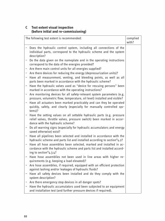
88
C Test extent visual inspection (before initial and re-commissioning)
The following test extent is recommended: complied with?
– Does the hydraulic control system, including all connections of the individual parts, correspond to the hydraulic scheme and the system description?
– Do the data given on the nameplate and in the operating instructions correspond to the data of the energies provided?
– Are there main control units for all energies supplied? – Are there devices for reducing the energy (depressurization units)? – Have all measurement, venting, and bleeding points, as well as all
parts been marked in accordance with the hydraulic scheme? – Have the hydraulic valves used as “device for rescuing persons” been
marked in accordance with the operating instructions? – Are monitoring devices for all safety-relevant system parameters (e.g.
pressure, volumetric flow, temperature, oil level) installed and visible? – Have all actuators been marked practicably and can they be operated
quickly, safely, and clearly (especially for manually controlled sys-tems)?
– Have the setting values on all settable hydraulic parts (e.g. pressure relief valves, throttle valves, pressure switch) been marked in accor-dance with the hydraulic scheme?
– Do all warning signs (especially for hydraulic accumulators and energy saved otherwise) exist?
– Have all pipelines been selected and installed in accordance with the hydraulic scheme and parts list and installed according to section°4.2?
– Have all hose assemblies been selected, marked and installed in ac-cordance with the hydraulic scheme and parts list and installed accord-ing to section°4.3.4?
– Have hose assemblies not been used in line areas with higher re-quirements (e.g. keeping a load elevated)?
– Are hose assemblies, if required, equipped with an efficient protection against lashing and/or leakages of hydraulic fluids?
– Have all safety devices been installed and do they comply with the system description?
– Are there emergency stop devices in all danger spots? – Have the hydraulic accumulators used been subjected to an equipment
and installation test (and further pressure devices if required).

89
D Test extent functional test
The following test extent is recommended: complied with?
– Have the setting values of all settable hydraulic parts been set in ac-cordance with the labeling and have the settings been saved?
– Does the hydraulic control system comply with the intended function and does this function correspond to the system description?
– Do all safety circuits work in accordance with the system description? – Do all emergency stop devices work and do they work in accordance
with the system description? – Is re-closing possible after complied safety conditions only? – Do the operation of the emergency stop not result in additional hazards
and the deactivation of the same not result in automatic start? – Are there no hazards due to interaction with linked systems (locks)? – Do the control devices for starting and shutting down work in accor-
dance with the system description? – Are all monitoring devices of the safety-relevant system parameters
functional? – Are the devices for reducing still existing energy efficient and can they
be used without any risks after disconnection from the energy supply? – Do switching the energy supply on and off, energy reductions, as well
as failure and return of the energy not lead to hazards? – Does using the system as intended not result in extraordinarily high
pressure surges or pressure boosts? – For testing any part of the hydraulic system with the maximum operat-
ing that can be achieved under all intended applications: – Have no measurable leakages occurred? – Did all hydraulic parts withstand the pressure? – Does the system temperature not exceed the thresholds specified in the
system description? – Does all user information relevant for operating the hydraulic system in
a safe manner exist (e.g. hydraulic scheme, parts list, system descrip-tion, drawings, operating/maintenance instructions, documents on hydraulic accumulators, safety data sheets on the hydraulic fluids used, etc.)?
– Furthermore for control specialists: – Does the simulated error case confirm the safety category (for redun-
dant control systems of the categories 3 and 4 according to EN 954-1 only)?
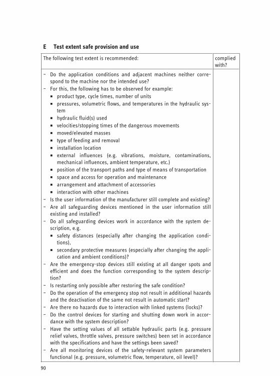
90
E Test extent safe provision and use
The following test extent is recommended: complied with?
– Do the application conditions and adjacent machines neither corre-spond to the machine nor the intended use?
– For this, the following has to be observed for example: product type, cycle times, number of units pressures, volumetric flows, and temperatures in the hydraulic sys-
tem hydraulic fluid(s) used velocities/stopping times of the dangerous movements moved/elevated masses type of feeding and removal installation location external influences (e.g. vibrations, moisture, contaminations,
mechanical influences, ambient temperature, etc.) position of the transport paths and type of means of transportation space and access for operation and maintenance arrangement and attachment of accessories interaction with other machines
– Is the user information of the manufacturer still complete and existing?– Are all safeguarding devices mentioned in the user information still
existing and installed? – Do all safeguarding devices work in accordance with the system de-
scription, e.g. safety distances (especially after changing the application condi-
tions), secondary protective measures (especially after changing the appli-
cation and ambient conditions)? – Are the emergency-stop devices still existing at all danger spots and
efficient and does the function corresponding to the system descrip-tion?
– Is restarting only possible after restoring the safe condition? – Do the operation of the emergency stop not result in additional hazards
and the deactivation of the same not result in automatic start? – Are there no hazards due to interaction with linked systems (locks)? – Do the control devices for starting and shutting down work in accor-
dance with the system description? – Have the setting values of all settable hydraulic parts (e.g. pressure
relief valves, throttle valves, pressure switches) been set in accordance with the specifications and have the settings been saved?
– Are all monitoring devices of the safety-relevant system parameters functional (e.g. pressure, volumetric flow, temperature, oil level)?
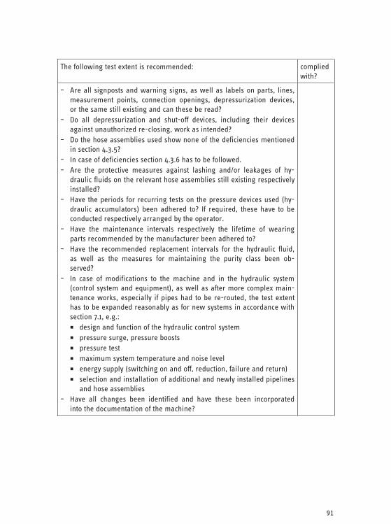
91
The following test extent is recommended: complied with?
– Are all signposts and warning signs, as well as labels on parts, lines, measurement points, connection openings, depressurization devices, or the same still existing and can these be read?
– Do all depressurization and shut-off devices, including their devices against unauthorized re-closing, work as intended?
– Do the hose assemblies used show none of the deficiencies mentioned in section 4.3.5?
– In case of deficiencies section 4.3.6 has to be followed. – Are the protective measures against lashing and/or leakages of hy-
draulic fluids on the relevant hose assemblies still existing respectively installed?
– Have the periods for recurring tests on the pressure devices used (hy-draulic accumulators) been adhered to? If required, these have to be conducted respectively arranged by the operator.
– Have the maintenance intervals respectively the lifetime of wearing parts recommended by the manufacturer been adhered to?
– Have the recommended replacement intervals for the hydraulic fluid, as well as the measures for maintaining the purity class been ob-served?
– In case of modifications to the machine and in the hydraulic system (control system and equipment), as well as after more complex main-tenance works, especially if pipes had to be re-routed, the test extent has to be expanded reasonably as for new systems in accordance with section 7.1, e.g.: design and function of the hydraulic control system pressure surge, pressure boosts pressure test maximum system temperature and noise level energy supply (switching on and off, reduction, failure and return) selection and installation of additional and newly installed pipelines
and hose assemblies – Have all changes been identified and have these been incorporated
into the documentation of the machine?
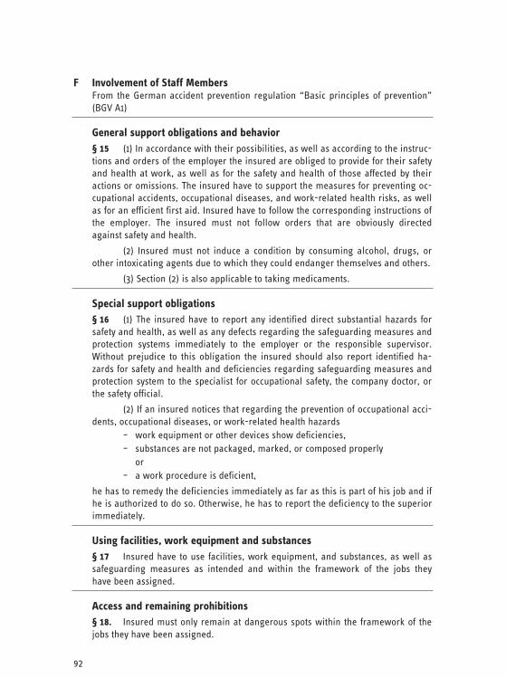
92
F Involvement of Staff Members From the German accident prevention regulation “Basic principles of prevention” (BGV A1)
General support obligations and behavior § 15 (1) In accordance with their possibilities, as well as according to the instruc-tions and orders of the employer the insured are obliged to provide for their safety and health at work, as well as for the safety and health of those affected by their actions or omissions. The insured have to support the measures for preventing oc-cupational accidents, occupational diseases, and work-related health risks, as well as for an efficient first aid. Insured have to follow the corresponding instructions of the employer. The insured must not follow orders that are obviously directed against safety and health.
(2) Insured must not induce a condition by consuming alcohol, drugs, or other intoxicating agents due to which they could endanger themselves and others.
(3) Section (2) is also applicable to taking medicaments.
Special support obligations § 16 (1) The insured have to report any identified direct substantial hazards for safety and health, as well as any defects regarding the safeguarding measures and protection systems immediately to the employer or the responsible supervisor. Without prejudice to this obligation the insured should also report identified ha-zards for safety and health and deficiencies regarding safeguarding measures and protection system to the specialist for occupational safety, the company doctor, or the safety official.
(2) If an insured notices that regarding the prevention of occupational acci-dents, occupational diseases, or work-related health hazards
– work equipment or other devices show deficiencies, – substances are not packaged, marked, or composed properly or – a work procedure is deficient,
he has to remedy the deficiencies immediately as far as this is part of his job and if he is authorized to do so. Otherwise, he has to report the deficiency to the superior immediately.
Using facilities, work equipment and substances § 17 Insured have to use facilities, work equipment, and substances, as well as safeguarding measures as intended and within the framework of the jobs they have been assigned.
Access and remaining prohibitions § 18. Insured must only remain at dangerous spots within the framework of the jobs they have been assigned.
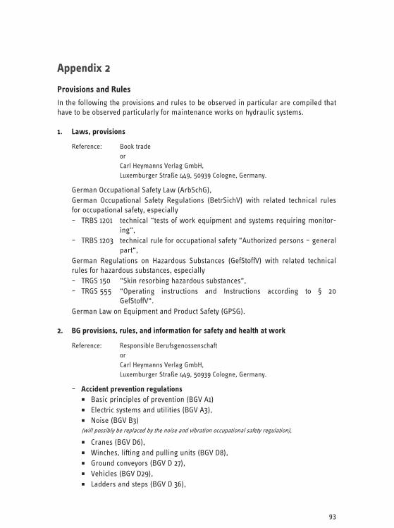
93
Appendix 2
Provisions and Rules
In the following the provisions and rules to be observed in particular are compiled that have to be observed particularly for maintenance works on hydraulic systems.
1. Laws, provisions
Reference: Book trade or Carl Heymanns Verlag GmbH, Luxemburger Straße 449, 50939 Cologne, Germany.
German Occupational Safety Law (ArbSchG), German Occupational Safety Regulations (BetrSichV) with related technical rules for occupational safety, especially – TRBS 1201 technical “tests of work equipment and systems requiring monitor-
ing“, – TRBS 1203 technical rule for occupational safety “Authorized persons – general
part“, German Regulations on Hazardous Substances (GefStoffV) with related technical rules for hazardous substances, especially – TRGS 150 “Skin resorbing hazardous substances“, – TRGS 555 “Operating instructions and Instructions according to § 20
GefStoffV“. German Law on Equipment and Product Safety (GPSG).
2. BG provisions, rules, and information for safety and health at work
Reference: Responsible Berufsgenossenschaft or Carl Heymanns Verlag GmbH, Luxemburger Straße 449, 50939 Cologne, Germany.
– Accident prevention regulations Basic principles of prevention (BGV A1) Electric systems and utilities (BGV A3), Noise (BGV B3)
(will possibly be replaced by the noise and vibration occupational safety regulation),
Cranes (BGV D6), Winches, lifting and pulling units (BGV D8), Ground conveyors (BGV D 27), Vehicles (BGV D29), Ladders and steps (BGV D 36),
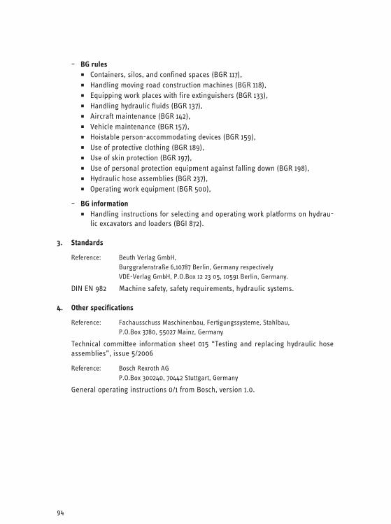
94
– BG rules Containers, silos, and confined spaces (BGR 117), Handling moving road construction machines (BGR 118), Equipping work places with fire extinguishers (BGR 133), Handling hydraulic fluids (BGR 137), Aircraft maintenance (BGR 142), Vehicle maintenance (BGR 157), Hoistable person-accommodating devices (BGR 159), Use of protective clothing (BGR 189), Use of skin protection (BGR 197), Use of personal protection equipment against falling down (BGR 198), Hydraulic hose assemblies (BGR 237), Operating work equipment (BGR 500),
– BG information Handling instructions for selecting and operating work platforms on hydrau-
lic excavators and loaders (BGI 872).
3. Standards
Reference: Beuth Verlag GmbH, Burggrafenstraße 6,10787 Berlin, Germany respectively VDE-Verlag GmbH, P.O.Box 12 23 05, 10591 Berlin, Germany.
DIN EN 982 Machine safety, safety requirements, hydraulic systems.
4. Other specifications
Reference: Fachausschuss Maschinenbau, Fertigungssysteme, Stahlbau, P.O.Box 3780, 55027 Mainz, Germany
Technical committee information sheet 015 “Testing and replacing hydraulic hose assemblies”, issue 5/2006
Reference: Bosch Rexroth AG P.O.Box 300240, 70442 Stuttgart, Germany
General operating instructions 0/1 from Bosch, version 1.0.