SAE J2579 Technical Information Report Fuel Systems in Fuel Cell & Other Hydrogen Vehicles Presented...
17
SAE J2579 Technical Information Report Fuel Systems in Fuel Cell & Other Hydrogen Vehicles Presented by Phil Horton To Hydrogen Fuel Cell Vehicle Subgroup on Safety May, 2008 SGS 3 - 6
-
Upload
kristin-murphy -
Category
Documents
-
view
221 -
download
1
Transcript of SAE J2579 Technical Information Report Fuel Systems in Fuel Cell & Other Hydrogen Vehicles Presented...

SAE J2579 Technical Information Report
Fuel Systems in Fuel Cell & Other Hydrogen Vehicles
Presented by Phil HortonTo Hydrogen Fuel Cell Vehicle Subgroup on Safety
May, 2008
SGS 3 - 6

Topics
Background
Summary of SAE J2579 General Structure Guiding Principles Compressed Hydrogen Performance Requirements
Key Attributes of SAE J2579
Validation Testing
Workplan for Next Steps
Summary

Background
Work on motor vehicle hydrogen storage system code initiated in SAE Fuel Cell Safety Work Group circa 2003.
Active participation by fuel cell vehicle and storage system manufacturers and testing organizations, including representation from Asia, Europe and North America.
Existing codes including NGV2, EIHP, FMVSS 304 and CSA B51 considered, with focus to develop design-independent performance-based code.
SAE J2579 balloted in late 2007 and published as Technical Information Report (TIR) in January 2008.
Two-year period for evaluation testing and workplan items with goal to publish SAE J2579 as Recommended Practice in early 2010.

SAE J2579 – General Structure1. Scope2. References3. Definitions4. General Requirements5. Performance Requirements
5.1 Liquified Hydrogen 5.2 Compressed Hydrogen
AppendicesA. Pressure Vessel TerminologyB. Material CompatibilityC. Compressed Hydrogen Qualification TestsD. Rationale for Section 5.2 Compressed Hydrogen
RequirementsE. Design and Selection of ComponentsF. Conducting Material Qualification TestsG. Compressed Hydrogen System Integration
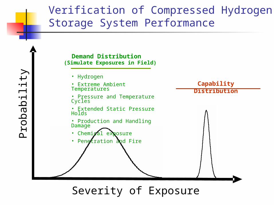
Verification of Compressed HydrogenStorage System Performance
Pro
babili
ty
Demand Distribution (Simulate Exposures in Field)
Capability Distribution
• Hydrogen• Extreme Ambient Temperatures• Pressure and Temperature Cycles• Extended Static Pressure Holds• Production and Handling Damage • Chemical exposure• Penetration and Fire
Severity of Exposure

Typical Compressed Hydrogen System
Container Vessel
ContainerIsolation
Valve
FillCheckValve
ExcessflowReceptacle
with check
Full SystemIsolation
LowPressure
Regulator
PRVPRV
HighPressure
Regulator
Downstream Hydrogen Piping for delivery to Fuel Cell
System or Engine
PRD
ServiceDefuelShufoff
vent
Compressed Hydrogen Containment System
Includes all components and parts that form the primary
pressure boundary for stored hydrogen
Isolates stored hydrogen from --
• the remainder of the fuel system
• the surrounding environment

Principle of “Design for Safety”
No single-point failure should cause unreasonable risk to safety or uncontrolled vehicle behavior:
Fail-safe design Isolation and separation of hazards to minimize cascading of
events Fault management with staged warnings and shutdowns
Isolation and containment of stored hydrogen is required to practice fault management on hydrogen and fuel cell vehicles.

Section 5.2 – Compressed Hydrogen Storage System Performance Requirements
Expected service performance test sequence (pneumatic pressure cycling)
Durability performance test sequence (hydraulic pressure cycling)
Performance under service-terminating conditions

Expected Service (pneumatic)
Pro
du
ctio
n
Pro
of
Pre
ssu
re
25%cy -40oCa
25%cy +50oCb,c
125%NWP
Expected-Service Performance Verification Test
180%NWP30 sec
150%NWP
500hr+85oC
500hr +85oC
25%cy +50oC25%cy -40oC 125%NWP
a System equilibration @ -40oC 5cy +20oC fuel; 5cy <-35oC fuelb System equilibration @ +50oC 5cy <-35oC fuelc Service defuel rate >50cy
* **
Pre
ss
ure
Lea
k/P
erm
eati
on
time
BurstBurst
<20%
5.2.2.1.1 5.2.2.1.2 5.2.2.1.4 5.2.2.1.5
5.2.3.1 5.2.2.1.25.2.2.1.3
5.2.2.3.3
125%NWP
5.2.2.1.1
Lea
k/P
erm
eati
on

Durability Performance
(hydraulic)
#Durability Cy125%NWP
30 sec180%NWP
10cy Tamb
150%NWP
Durability Performance Verification Test
5.2.2.2.35.2.2.2.2
5.2.2.2.1
150%NWP
5.2.2.1.4
Pro
of
Pre
ssu
re
5.2.3.1
Pre
ss
ure
Fla
ws
& C
hem
Dro
p
time
burst
5.2.2.1.5
burst <20%
48hr125%NWP

Service Terminating Conditions
Bonfire No burst & controlled PRD release
Penetration No burst
Burst Pressure
Cycle Life
Manufacturer will establishnew-vessel burst pressure and cycle life criteria

Key Distinctions from other Pressure Vessel Codes
System-level performance code that is independent of storage system design.
Uses two sequences of tests (expected service and durability performance) rather than discrete testing of virgin tanks.
Specifies end-of-life (EOL) burst margins rather than beginning-of-life (BOL) burst margins.
In addition to requiring EOL burst margin to be at least 1.8 times maximum working pressure, also requires EOL burst pressure to be at least 80% of virgin-tank burst pressure.
Includes pneumatic cycling and sustained stand time (in expected service sequence).

19.03.2008 | Presented by Livio Gambone, P.Eng.
SAE J2579 TEST PROGRAMResults Update
> Powertech Labs

Project Background

Test Plan
1. Determine time and feasibility to perform SAE J 2579 test using carbon/ polymer tank (gas & hydraulic in parallel) – done
2. Subject carbon/ polymer tank to the gas cycle test with end plug –done
3. Subject carbon/ Al tank to the gas cycle test with end plug – done4. Subject carbon/ Al tank with valve to the gas cycle test – underway5. Subject carbon/ polymer tank to the hydraulic test - done6. Subject carbon/ Al tank to the hydraulic test - done7. Subject glass/ Al tank (with known field failure) to hydraulic test -
done8. Subject carbon/ polymer tank with valve to gas cycle test – planned

Workplan for 2008 and 2009
Complete validation testing, and revise SAE J2579 as appropriate based on findings.
Develop localized fire test procedure(s) and performance criteria for possible inclusion in SAE J2579.
Consider refinements to specific provisions based on additional data analyses:
Permeation requirements Number of pressure cycles Hold times and temperatures
Criteria for redesign not requiring re-qualification. Re-qualification for additional service. Criteria for allowing parallel (versus series)
performance testing.

Summary
SAE J2579 provides performance based system level requirements to assess hydrogen storage safety while also facilitating future improvements in technology.
Validation testing scheduled for completion during 2008.
Pending successful completion of validation testing, SAE J2579 should be considered as basis for hydrogen storage portion of FCV Global Technical Regulation.