RISK Assessment AS2885 Pipeline
40
Appendix E Trans Territory Pipeline - Preliminary Risk Assessment in Accordance with AS2885 for the Trans Territory Pipeline prepared by OSD Energy Services
-
Upload
luispinda-dazacol -
Category
Documents
-
view
53 -
download
8
Transcript of RISK Assessment AS2885 Pipeline

Appendix E
Trans Territory Pipeline - Preliminary Risk Assessment in Accordance with AS2885 for the Trans Territory Pipeline prepared by OSD Energy Services


© OSD Energy Services, 2004
Preliminary Risk Assessment inAccordance with AS 2885 for the
Trans Territory Pipeline
Prepared by:
OSD Energy ServicesLevel 9, Toowong Tower
9 Sherwood Road
Toowong QLD 4066

© OSD Energy Services, 2004
Limitations Statement
This report has been prepared on behalf of and for the exclusive use of Alcan, and issubject to and issued in connection with the provisions of the agreement between OSDEnergy Services and Alcan. OSD Energy Services accepts no liability or responsibilitywhatsoever for or in respect of any use of or reliance upon this report by any thirdparty.

OSD Energy Services Page 1 of 24
CONTENTS
1 SUMMARY ............................................................................3
2 ROUTE DESCRIPTION ...........................................................4
3 RISK ASSESSMENT PROCESS.................................................43.1 Location Analysis ...................................................................... 53.2 Risk Analysis ........................................................................... 5
4 PIPELINE DESCRIPTION .......................................................54.1 Pipeline Design ........................................................................ 54.2 Pipe ...................................................................................... 64.3 Coating.................................................................................. 64.4 Cathodic Protection................................................................... 64.5 Cover.................................................................................... 64.6 Valve Stations ......................................................................... 64.7 Road Crossings........................................................................ 74.8 Watercourse Crossings .............................................................. 74.9 Railway Crossing...................................................................... 84.10 Other Utility Services ................................................................ 84.11 Operation and Control ............................................................... 84.12 Procedures and Plans ................................................................ 84.13 Gas Description........................................................................ 8
5 RISK MITIGATION – PROTECTION MEASURES........................95.1 Physical Measures .................................................................... 9
5.1.1 Separation by Burial....................................................... 95.1.2 Resistance to Penetration................................................ 95.1.3 Separation by Exclusion.................................................. 9
5.2 Procedural Measures – Marking..................................................10
5.2.1 Dial Before You Dig ......................................................105.2.2 Signage .....................................................................105.2.3 Marker Tape ...............................................................105.2.4 Patrols .......................................................................105.2.5 Landowner, Occupier and Other Authority Liaison................10
6 RISK IDENTIFICATION .......................................................116.1 Location Analysis Discussion ......................................................116.2 Threat Analysis .......................................................................11
6.2.1 Location Specific Threats ...............................................126.2.2 General Threats...........................................................12
7 RISK EVALUATION..............................................................137.1 General.................................................................................137.2 Consequence Analysis ..............................................................147.3 Risk Estimation Matrix ..............................................................15

OSD Energy Services Page 2 of 24
8 RISK EVALUATION..............................................................168.1 Third Party Interference ...........................................................16
8.1.1 Private Development ....................................................168.1.2 Residential Developments ..............................................168.1.3 Public Developments and Maintenance..............................178.1.4 Mining Development .....................................................178.1.5 Rural Development.......................................................18
8.2 Corrosion...............................................................................198.3 Electrical Induction ..................................................................198.4 Explosive Atmospheres.............................................................208.5 Cyclones and Strong Winds .......................................................208.6 Flooding................................................................................208.7 Excessive Vehicular Load...........................................................218.8 Train Derailment .....................................................................218.9 Road Maintenance...................................................................218.10 Earthquakes...........................................................................228.11 Bushfire ................................................................................228.12 Testing and Inspection .............................................................228.13 Farming Activities....................................................................238.14 Hunting Activities ....................................................................238.15 Sabotage and Vandalism...........................................................248.16 Erosion of Cover .....................................................................248.17 Failure of Control and Protective Equipment ..................................248.18 Inadequate or Incomplete Maintenance........................................248.19 Erosion and Sediment Control ....................................................248.20 Stream Crossings ....................................................................25
APPENDIX ALocation and Threat Analysis
APPENDIX BTypical Gas Composition

TRANS TERRITORY P IPELINE (TTP)
OSD Energy Services Page 3 of 25
1 SUMMARY
This document details the preliminary desktop Risk Assessment which has beencarried out as part of the Trans Territory Pipeline (TTP) feasibility study to ensurethat the route and pipeline construction parameters considered during that studydid not involve any risks which could not be made acceptable by either design orprocedural measures. It is not to be considered to be a definitive AS2885.1 RiskAssessment for the final pipeline design but it may be used as a guideline whenpreparing that definitive Risk Assessment.
The AS 2885 risk assessment methodology is a continuous process. This processrequires a review of the risk assessment document, triggered by time orsignificant change of threats affecting the pipeline.
A preliminary risk assessment of the proposed TTP was undertaken inaccordance with Australian Standard, AS 2885. A further ‘team workshop’ reviewof the risk assessment by experienced personnel will be prepared when thepipeline route has been refined during the process of detailed design. At leastevery five years during the life of the pipeline, in accordance with AS 2885, therisk assessment will be reviewed and revised to account for any changedconditions.
The Preliminary Risk Assessment is a desktop study based on informationobtained from various site visits and surveys, and from maps and photos.
The Preliminary Risk Assessment is a qualitative risk assessment and has beencompleted to meet the requirements of Section 7.1 of the Final EIS Guidelines.With TTP transporting gas over approximately 940 km, there are many variationsin the location classes and types through which the pipeline passes. Theintention of the methodology outlined in AS 2885 is to ensure that all possiblethreats at the different location classes and types are identified, evaluated andmanaged at all stages over the life of the pipeline.
The location analysis has noted a series of features along the pipeline route andhas identified threats associated with each feature. Where possible, risk hasbeen minimised through route selection. Each threat has been systematicallyassessed and risk mitigation methods identified to reduce all risk to As Low AsReasonably Practicable (ALARP). The risk mitigation methods include bothphysical and procedural measures.
The pipeline will be constructed to Australian Standard 2885.1-1997(incorporating Attachment No 1 - April 2001): Pipelines - Gas and LiquidPetroleum Part 1 Design and Construction. The Pipeline will be maintained andoperated in accordance with AS 2885.3-2001: Pipelines - Gas and LiquidPetroleum - Part 3 Operation and Maintenance.

TRANS TERRITORY P IPELINE (TTP)
OSD Energy Services Page 4 of 25
2 ROUTE DESCRIPTION
Alcan is proposing to convert its Gove Alumina Refinery to operate on naturalgas, to be supplied from the Blacktip field in the Bonaparte Basin. The projectwill require construction of a natural gas pipeline from Wadeye to Gove to carrythe gas from an onshore processing plant near Wadeye.
The project is a 940 km high pressure gas pipeline from Wadeye to Gove, viaKatherine, and will have provision for installation of future compressor stations.The Trans Territory Pipeline will commence at a flange downstream of anonshore facility at Wadeye and will terminate at a flange downstream of themeter and pressure reduction station within the boundary of Alcan’s aluminarefinery on the Gove Peninsula.
A pipeline route alignment has been identified within a 10 km corridor of interestthat traverses the Northern Territory, noting that this is being progressivelyreduced to a 100m survey corridor by field and aerial surveys. The pipeline routeis being developed based on the outcomes of cultural heritage, environmentaland engineering investigations.
Areas adjacent to the pipeline are sparsely populated and fall into the category ofR1 – Broad Rural as defined by AS 2885, except in parts of the Nhulunbuy areawhich falls into the category T1 – Suburban, and an area north of the KatherineRiver near Katherine that falls in the category R2 – semi-rural.
3 RISK ASSESSMENT PROCESS
The Trans Territory Pipeline Risk Assessment was completed by assessing thepipeline for both location specific threats and general threats to the pipeline,their likelihood of occurrence and their effect if they were to occur. The effectsfrom worst scenario cases of failure were considered with respect to:
q Safety of the public
q Safety of employees and contractors
q Environmental impact
q Economic loss
Risk mitigation methods to be employed were also assessed on the basis ofreducing risk to ALARP (As Low As Reasonably Practicable) in accordance withAustralian Standard 2885 requirements. Risk mitigation is detailed further inSection 5.

TRANS TERRITORY P IPELINE (TTP)
OSD Energy Services Page 5 of 25
3.1 LOCATION ANALYSIS
Data gathered from aerial surveys, ground surveys and mapping of the route wasused to perform a location analysis and feature identification of the pipeline.This documentation was used to correlate features identified during the routesurvey with locations.
3.2 RISK ANALYSIS
Risk analysis was performed on the threats identified in the location analysisprocess and on threats generally associated with pipelines. The risk analysis wasperformed in accordance with AS 2885.1-1997 and based on the guidelines ofSAA HB105-1998. The AS 2885 risk assessment process is similar to that ofAS 4360 so there is no differentiation made between natural hazard risks or anyother risks within the risk analysis.
The standard prescribes a risk analysis process that assesses the frequency ofoccurrence of threats to the pipeline and the probability that each threat willresult in a loss of integrity or containment of the asset. The consequence of theasset failing is then required to be assessed for the impact on the locality aroundthe possible incident. Impact on the surrounding area is assessed with regard tosafety, the environment and economic cost.
The aim of the risk analysis is to reduce the residual risk of an incident to a lowranking or ALARP, by applying physical design controls. In an operating pipelinesituation, the risk assessment process may require additional procedural factorsof protection to be applied if the pipeline does not fall into a safe enoughoperating regime through design above.
These requirements are considered in this risk assessment.
4 PIPELINE DESCRIPTION
4.1 PIPELINE DESIGN
The pipeline is a welded steel pipeline to be operated in accordance withAustralian Standard AS 2885.3–2001.
The pipeline shall be designed to a MAOP of 15.3 MPag in accordance withAS 2885.1 – 1997 (incorporating amendment No 1).
Features along the pipeline route are detailed in Appendix A.

TRANS TERRITORY P IPELINE (TTP)
OSD Energy Services Page 6 of 25
4.2 PIPE
The pipeline as currently selected shall be constructed from API 5L – X70(482 MPa SMYS), 406.4 mm outside diameter pipe. In this case, pipe for R1locations would have a wall thickness of 9.0 mm, and that for stations, roadcrossings and other special crossings would have a wall thickness of 10.8 mm.Manufactured bends would also use the thicker pipe to allow for wall thinning.
4.3 COATING
All linepipe shall be externally coated with a high integrity factory applied coating(dual layer Fusion Bonded Epoxy (FBE) or Trilaminate) coating in accordancewith project specifications. The field joint coating system shall be compatiblewith the parent coating material and in accordance with a project specification.
The coating is the primary corrosion protection, with the cathodic protectionproviding secondary protection at any coating defects.
4.4 CATHODIC PROTECTION
The pipeline shall be protected from corrosion by impressed current systemslocated along the pipeline as required.
Provision has been made at each scraper facility and each mainline valve (MLV)for installation of cathodic protection anode beds.
4.5 COVER
The pipeline will be buried in accordance with the requirements of AS 2885 to aminimum of 750 mm in R1 locations, 1,200 mm in road, railway reserves and anyother higher risk areas, as well as at least 2,000 mm below watercourses orareas subject to erosion.
4.6 VALVE STATIONS
The pipeline will be fitted with valve stations as indicated in the table below.
The stations at KP 0, 76, 234, 364, 485, 638, 797, 932 and 943 will be fitted withtelemetry, instrumentation and with valve actuators, so that the main line valvescan be operated remotely from the pipeline control room, in normal oremergency operation.
The valve station at KP 915 will be fitted with a pressure reduction valve todecrease the line pressure at the Gove end of the pipeline. This station will be

TRANS TERRITORY P IPELINE (TTP)
OSD Energy Services Page 7 of 25
fitted with telemetry and instrumentation so it can be monitored and controlledfrom the pipeline control room
The valve spacings comply with the requirements of AS 2885 and provide forgood control over the pipeline.
KP Location Facilities
0 Wadeye Launcher, Metering + MLV
76 Tom Turners Crossing Scraper + MLV
162 Wingates MLV + Future Compression
234 Dorisvale Scraper + MLV
282 Florina MLV
322 Manbulloo Interconnect Offtake
364 King River Scraper, Compression + MLV
419 Beswick MLV
485 Velkerri Creek Scraper + MLV
533 Mainoru MLV + Future Compression
638 Annie Creek Scraper + MLV
728 Guluddy Creek MLV
797 Gapuwiyak Road Scraper + MLV
915 Giddy River PRV + MLV
932 Nhulunbuy MLV (Remote)
936 Nhulunbuy Offtake Offtake
943 Gove Receiver, Metering, Heating, PressureReduction + MLV
4.7 ROAD CROSSINGS
The pipeline depth of cover shall be at least 1,200 mm in road reserves. The NTGovernment has requested 1,000 mm minimum under table drains and1,500 mm at the road shoulder of highways.
4.8 WATERCOURSE CROSSINGS
Watercourse crossings shall be buried deeper than 2,000 mm below the bottomof the watercourse.

TRANS TERRITORY P IPELINE (TTP)
OSD Energy Services Page 8 of 25
4.9 RAILWAY CROSSING
The pipeline depth of cover shall be at least 1,200 mm below table drain of theAlice Springs-Darwin railway reserve and at least 3,000 mm below top of the rail.
4.10 OTHER UTILITY SERVICES
Adequate separation (300 mm minimum for crossings and 1,000 mm minimumfor parallel) shall be kept between the pipeline and other utility services toensure neither impacts on the other.
4.11 OPERATION AND CONTROL
Pipeline and station control systems shall all be fail safe.
The pipeline shall be protected from overpressure by pressure control and asecond pressure limiting system at the pipeline inlet and at compressor stations.
The pipeline shall be fitted with telemetry, communications, instrumentation andSCADA to allow pipeline operations to reliably monitor, control and operate thepipeline.
4.12 PROCEDURES AND PLANS
The pipeline will be maintained and operated in accordance with a set ofoperating, maintenance and repair procedures.
These will be developed into a set of safety, operating and emergency responseplans, which will take account of proper operation of the pipeline includingenvironmental issues.
4.13 GAS DESCRIPTION
The gas transported in the pipeline will be non-toxic industrial quality naturalgas. It will have a low water dewpoint and be non corrosive, thus providingcorrosion protection to the internal surface of the pipeline.
Emissions of gas will be kept to a minimum, with the pipeline having highintegrity from leakage and only minimal venting of gas taking place duringoperations.

TRANS TERRITORY P IPELINE (TTP)
OSD Energy Services Page 9 of 25
5 RISK MITIGATION – PROTECTIONMEASURES
The following risk mitigation measures are referenced in the pipeline locationanalysis, which can be found in Appendix A.
5.1 PHYSICAL MEASURES
5.1.1 Separation by Burial
The pipeline shall be constructed with a depth of cover of 750 mm or greater. Inaddition pipe within road reserves shall be buried to at least 1,200 mm.
This depth meets AS 2885.1-1997 requirement of burial not less than 750 mmfor land designated R1 – Broad Rural. The majority of the land along thepipeline route falls within the category designated R1 – Broad Rural (ie largerthan 5 ha lots).
API 5L-X70 pipe of 9.0 mm wall thickness buried at 750 mm is adequate towithstand a wheel loading in excess of 14 tonne, so the depth of burial isassessed as adequate (assessed in accordance with API 1102).
In road reserves, where there is greater possibility of third party impact frommachine excavation, the pipeline will be buried with at least 1200mm cover toplace it below any expected excavations.
Increased burial depth may also be required in some areas, if land use involvesany deep ripping or extensive cultivation.
5.1.2 Resistance to Penetration
The pipeline shall be constructed from pipe with a wall thickness minimum of atleast 9.0 mm. Pipe crossing roads will also have a thicker wall thickness of atleast 10.8 mm.
Studies from France and England show that pipe with a wall thickness of 9.0 mmor greater is highly resistant to rupture from third party activity. A researchproject undertaken by the Australian Pipeline Industry through the CRC forMaterials Welding and Joining in 2000, and a subsequent project in 2001 hasverified overseas correlations.
5.1.3 Separation by Exclusion
The above ground pipework shall be protected by fencing.

TRANS TERRITORY P IPELINE (TTP)
OSD Energy Services Page 10 of 25
This meets the SAA HB105 – 1998 pipeline risk assessment requirement ofhaving at least one physical protection measure for a pipeline in located in anarea designated as R1 – Rural.
Sections of the pipeline which may be at risk from routine activities (ditchclearing along roads for example) may require additional protection by concreteslabs.
5.2 PROCEDURAL MEASURES – MARKING
5.2.1 Dial Before You Dig
Trans Territory Pipeline will provide a Dial Before You Dig service. The servicewill be available 24 hours a day. Trans Territory Pipeline personnel will visitproperties to locate the pipeline when required.
5.2.2 Signage
AS 2885.1-1997, Table 4.2.4.6, states the maximum sign spacing allowable isinter-visible but no more than 5,000 m in R1 reducing to 500 m in T1. Signageon the Trans Territory Pipeline shall be intervisible in both directions along theentire pipeline route and spacing shall not exceed 500 m. Signage will also bepresent on both sides of road crossings, both sides of railway crossings, bothsides of significant river and stream crossings, at all fences, at all utility crossingsand at all changes of direction (bends). An emergency contact number will beshown on the signs.
5.2.3 Marker Tape
In locations where additional protection is deemed necessary, marker tape maybe installed above the pipe to warn third parties of the presence of the buriedpipeline.
5.2.4 Patrols
Patrolling of the pipeline will occur at regular intervals not exceeding six monthly.
5.2.5 Landowner, Occupier and Other Authority Liaison
Third party awareness is an important protection measure. Correspondence willbe posted to each landholder, occupier and other utility provider at leastannually.

TRANS TERRITORY P IPELINE (TTP)
OSD Energy Services Page 11 of 25
Landowners and occupiers shall also visit personally at least annually, and in anycase regular contact will be made whenever patrols are conducted. Regularcontact will also be made with the local superintendents of other utility providers.
6 RISK IDENTIFICATION
The AS 2885.1–1997 Risk Assessment Methodology was used for riskidentification and evaluation. The area of influence examined during the riskassessment included facilities and features of note within 580 m of the pipelineroute.
The area of influence was determined by looking at the furthest distance where aradiation level of 4.7 kW/m2, which has the potential to cause injury, would resultfrom full pipeline rupture resulting in a fire. Calculations used to determine thearea of influence are based on a DN400 pipeline operating at a pressure of15.3 MPa with maximum feed of gas to a fire. Maximum feed of gas to a fire isassumed to be equal to release of gas through a hole of equal size to the pipediameter, with the pressure gradient between atmospheric pressure and15.3 MPa driving the flow.
The same worst case scenario could potentially cause fatalities at 354 m, thedistance where radiation intensity is 12.6 kW/m2. The calculated area ofinfluence is likely to be significantly less than this as there is only a lowprobability that third party damage will cause a full bore rupture, with the greaterlikelihood being a hole or pinhole with concomitant area of influence significantlysmaller.
For example a 5 mm hole will cause a 12 m and 7 m distance respectively,versus the 580 m and 354 m for a full bore rupture.
Radiation intensity values of 4.7 kW/m2 and 12.6 kW/m2 correspond to thevalues where 30 seconds exposure will lead to at least second degree burns, andthird degree burns with a possible fatality, respectively.
6.1 LOCATION ANALYSIS DISCUSSION
The location analysis was performed along the pipeline from a desktop analysis.
The location classification for the whole of the pipeline route was R1 - BroadRural, other than the Gove end which is classified as T1 - Suburban.
6.2 THREAT ANALYSIS
The threat analysis was performed with two focuses: one focus on locationspecific threats (Appendix A), and the second on general threats found to apply

TRANS TERRITORY P IPELINE (TTP)
OSD Energy Services Page 12 of 25
in many locations along the pipeline length, such as external interference. Thesegeneral threats are considered further in Section 8 of this report.
6.2.1 Location Specific Threats
Location specific threats are tabulated in Appendix A.
The pipeline is divided into sections, or locations, for which threats specific tothat location are identified. Each location is named in the table and protectionmeasures mitigating against the threats provided. Protection measures areselected from a subset of the physical and procedural measures defined inAS 2885.1–1997 identified at Section 5. They are considered adequate if theymeet AS 2885 requirements particular to the location classification and reducethe risk to ALARP.
A ‘comments’ column is included in the table to contain details of special interestfeatures, irregular activities, or action items for identified risks requiring specialinterest.
6.2.2 General Threats
Issues considered include:
q external interference (third party activity)
q corrosion (internal, Stress Corrosion Cracking (SCC), Hydrogen SulphideCracking and external)
q electrical induction (lightning, power line induction)
q explosive atmospheres
q cyclones and strong winds
q flooding
q excessive vehicular load
q train derailment
q road maintenance
q earthquakes
q bushfire
q testing and inspection

TRANS TERRITORY P IPELINE (TTP)
OSD Energy Services Page 13 of 25
q farming activities
q mining activities
q sabotage and vandalism
q erosion of cover
q failure of control and protective equipment
q inadequate or incomplete maintenance
q erosion and sediment control
q stream crossings
7 RISK EVALUATION
7.1 GENERAL
AS 2885 requires the frequency of a pipeline threatening event to be assessedaccording to the following classification.
Frequency ofOccurrence
Description
Nearest NumericalFrequency for
Guidance(per 1,000 km/yr)
Frequent Expected to occur at least once peryear
1 or greater
Occasional Expected to occur several times in thelife of the pipeline
0.1
Unlikely Not likely to occur in the life of thepipeline, but is possible
0.01
Remote Very unlikely to occur in the life of thepipeline
0.001
Improbable Examples of this event have occurredhistorically, but it is not anticipated forthe pipeline at this location
10-5
Hypothetical Theoretically possible, but has neveroccurred to date
10-6 or lower
AS 2885 also requires determination of the severity arising from anincident/event. The following definitions are used to categorise severity.

TRANS TERRITORY P IPELINE (TTP)
OSD Energy Services Page 14 of 25
Severity Class Description
Catastrophic Applicable only in location classes T1 and T2 wherethe number of humans within the range of influenceof the pipeline would result in many fatalities
Major Event causes few fatalities or loss of continuity ofsupply or major environmental damage
Severe Event causes hospitalising injuries or restriction ofsupply
Minor Event causes no injuries or loss of supply
The frequency and severity are then considered together to determine a riskranking. Risks are categorised as either HIGH, INTERMEDIATE, LOW orNEGLIGIBLE. Design criteria and operational procedures are put in place to shiftthe risk ranking towards the risk classifications of LOW and NEGLIGIBLE. A riskfalling into the risk classification of INTERMEDIATE is acceptable according toAS 2885.1-1997, but only after recursive evaluation confirms this risk ranking andrisk management actions have been applied to achieve a risk of ALARP.
Generally, according to AS 2885, a frequency lower than IMPROBABLE (10-5) canbe acceptable for all other than a CATASTROPHIC event (ie events that do notcause greater than a few fatalities, major loss of supply or major environmentaldamage).
Risks identified on the pipeline will be assessed in accordance with the SAAHB105 – 1998 guidelines for likelihood of impact against the frequencydefinitions defined above, during detail design.
7.2 CONSEQUENCE ANALYSIS
The upper bound of events, other than an explosion, is usually defined on apipeline as a full-bore rupture of the pipeline with a fire. The intensity of any firecan be calculated from the diameter of the pipeline, the operating pressure andthe size of the rupture. Intensity values of 4.7 kW/m2 and 12.6 kW/m2 are takenfrom document HB105–1998, and correspond to the values where 30 secondsexposure will lead to at least second degree burns, and third degree burns with apossible fatality, respectively.
Calculations used to determine the area of influence are based on a DN400pipeline operating at a pressure of 15.3 MPa with maximum feed of gas to a fire.Maximum feed of gas to a fire is assumed to be equal to release of gas through a

TRANS TERRITORY P IPELINE (TTP)
OSD Energy Services Page 15 of 25
hole of equal size to the pipe diameter, with the pressure gradient betweenatmospheric pressure and 15.3 MPa driving the flow.
The area of influence examined during the risk assessment included facilities andfeatures of note within 580 m of the pipeline route. The same worst casescenario could potentially cause fatalities at 354 m. The calculated area ofinfluence is likely to be significantly less than this as there is only a lowprobability that third party damage will cause a full bore rupture, with the greaterlikelihood being a hole or pinhole with areas of influence significantly smaller.Pressure within the pipeline is also likely to be less than the Maximum AllowableOperating Pressure (MAOP) at most points along the pipeline.
These intensity values can be used to place an upper bound on the consequenceof a pipeline rupturing event.
7.3 RISK ESTIMATION MATRIX
The risk of an event is categorised using its likelihood and severity rankings inthe risk estimation matrix from AS 2885.1 – 1997 shown below.
Severity ClassFrequencyof
Occurrence Catastrophic Major Severe Minor
Frequent H H H I
Occasional H H I L
Unlikely H H L L
Remote H I L L
Improbable H I L N
Hypothetical I L N NRisk Classes:H = High I = Intermediate L = Low N = Negligible

TRANS TERRITORY P IPELINE (TTP)
OSD Energy Services Page 16 of 25
8 RISK EVALUATION
8.1 THIRD PARTY INTERFERENCE
Third party activity is recognised in the pipeline industry as one of the high riskthreats to a pipeline. The pipeline wall thickness, depth of burial and proceduralmeasures will reduce the risk to a low risk ranking.
Third party interference has been grouped under the following headings in orderto facilitate this risk assessment.
8.1.1 Private Development
Typical threats associated with private development or maintenance include:
q fencing
q access roads
q installation of new services (ie gas, phone, sewerage, drainage)
q erection of structures such as sheds
q gardening/landscaping
Liaison with landholders and utility providers, and patrolling should almosteliminate this risk.
New services may be installed for domestic or industrial use. Domestic servicesare generally not installed at great depth or using equipment which could impacton the integrity of the pipeline. Industrial service lines are installed at a greaterdepth, and regular contact with utility providers is needed to reduce this risk.Any vehicular load risk will be minimised by the depth of burial, and pipe wallthickness.
8.1.2 Residential Developments
Residential development activity is unlikely to impact the pipeline as the locationof the pipeline is away from any densely populated area.
Typical threats associated with new residential developments or residentialmaintenance include:
q building of houses
q building of garages, sheds, decks

TRANS TERRITORY P IPELINE (TTP)
OSD Energy Services Page 17 of 25
q landscaping
q driveways and footpaths
q installation of new services (ie gas, phone, water, sewage, drainage,electricity, etc)
q power poles and lighting poles
q roads and table drains
q commercial centres
The rural routing of this pipeline is well away from farm buildings, making thisthreat low. No building structures were within 600 m of the pipeline, except forone house which was located approximately 200 m from the pipeline.
8.1.3 Public Developments and Maintenance
Threats from public developments and maintenance include:
q road and table drain maintenance (typically utilising 14 G grader orequivalent for resurfacing)
q maintenance of public facilities, such as power and lighting poles
q maintenance of public services (water, sewage, telecommunication cable andfibre optic, overhead and underground power, gas and oil pipelines, anddrains)
q installation of new services (water, sewage, telecommunication cable andfibre optic, overhead and underground power, gas and oil pipelines, anddrains)
It is possible that some of these activities may reach or exceed a depth of750 mm. The pipeline will be buried to a depth of 1,200 mm within roadreserves, thereby minimising any threat. Risks include those from installation ofnew services, especially if boring or directional drilling is used. Liaison withpublic utility providers associated with the above activities will reduce the risk ofdamage from third party activity.
8.1.4 Mining Development
A number of activities associated with mining in the areas in which the pipeline islocated are assessed as possible threats to the pipeline.

TRANS TERRITORY P IPELINE (TTP)
OSD Energy Services Page 18 of 25
These include:
q exploration drilling
q seismic surveying
q blasting
q crossing of the pipeline with heavy equipment
q test excavations
q new roads
It is likely that these activities will pose a threat to the pipeline. Signage, thecleared right-of-way (ROW) and liaison with mining companies will minimise anythreat. Regular pipeline route inspections will provide an important measure tominimise the risk.
8.1.5 Rural Development
A number of activities associated with farming the land in which the pipeline islocated are assessed as possible threats to the pipeline. These include:
q deep ripping
q fencing
q dams
q sheds
q contour banks
Some of these activities are likely to reach or exceed a depth of 750 mm. In anyproperties where deep ripping may take place pipeline will require additionaldepth of burial. Liaison with rural landholders will reduce the risk from thirdparty activity.
The risk is assessed as having a severity class of MAJOR and a frequencyoccurrence rating of IMPROBABLE. This risk is reduced to INTERMEDIATE and isconsidered to be ALARP.

TRANS TERRITORY P IPELINE (TTP)
OSD Energy Services Page 19 of 25
8.2 CORROSION
All pipeline steels can be affected by corrosion.
The Trans Territory Pipeline has been risk assessed for corrosion causing loss ofintegrity as follows:
q External Corrosion
q The external surface of the pipeline is installed in a corrosiveenvironment.
q The pipeline will be operating in the pressure range of up to 72% SMYS.Stress corrosion cracking of the pipeline steel can take place at thispressure, particularly as the steel will be subjected to cyclic pressures.
q Internal Corrosion
q The flowing gas has low sulphur and low water dewpoint. These gasqualities protect the pipe internals from corrosion.
The pipe will be coated with dual layer epoxy as the primary corrosion protection,and cathodic protection will be applied to protect any coating damaged areas.
Procedures will ensure that the pipeline cathodic protection levels are maintainedto protect the pipeline from all types of corrosion.
The risk is assessed as having a severity class of SEVERE and a frequencyoccurrence rating of IMPROBABLE. This risk is reduced to LOW.
8.3 ELECTRICAL INDUCTION
Lightning striking the pipeline is capable of inducing significant voltages into thepipeline. There are no other high structures adjacent to the pipeline to attractlightning away from the pipeline.
There are powerlines paralleling the pipeline capable of inducing an electricalvoltage in the pipeline from KP 932 through to the Gove Gate Station. Designtechniques will be applied to protect equipment and personnel and to dissipateenergy away safely.
The risk is assessed as having a severity class of SEVERE and a frequencyoccurrence rating of REMOTE. This risk is reduced to LOW.

TRANS TERRITORY P IPELINE (TTP)
OSD Energy Services Page 20 of 25
8.4 EXPLOSIVE ATMOSPHERES
An explosive atmosphere exists when the natural gas in air concentration falls inthe range of 4%-15%. Generally, this cannot occur for a leakage of natural gasin a freely ventilated area where gas can disperse. Natural gas is lighter than airand it will naturally disperse upwards away from the source of a leak, andtherefore will not concentrate.
The risk is assessed as having a severity class of MAJOR and a frequencyoccurrence rating of HYPOTHETICAL. This risk is reduced to LOW.
8.5 CYCLONES AND STRONG WINDS
The Main Line Valves will be buried and not subject to cyclone damage.
The scraper stations will have some above ground pipe work. This pipe work isresistant to damage by impact from natural materials as the pipe steel will have adesign factor of 0.6, and the main pipeline steel is 10.8 mm thick. Evenmanufactured materials (such as a vehicle) impacting the pipe would be unlikelyto cause major damage to the pipe.
Smaller valves at a station could be broken off causing a smaller leak. This islikely to cause a small jet fire at worst.
All facilities will be fenced providing protection against wind driven debris (exceptfor extra high velocity wind).
Control buildings (small) and compressor buildings shall be built to the NorthernTerritory building code to withstand the effects of cyclones and strong winds.
Most facilities and stations will be located more than 100 km from the coastwhere cyclone based effects are diminished.
The risk is assessed as having a severity class of SEVERE and a frequencyoccurrence rating of REMOTE. This risk is reduced to LOW.
8.6 FLOODING
The pipeline shall be buried at least 2,000 mm below rivers and watercourses.
Stations and facilities will be located on higher areas not subject to flooding.
In areas where pipeline flotation could occur such as rivers the pipe will haveweight coating or some other means to provide negative buoyancy.
The risk is assessed as having a severity class of MINOR and a frequencyoccurrence rating of REMOTE. This risk is reduced to LOW.

TRANS TERRITORY P IPELINE (TTP)
OSD Energy Services Page 21 of 25
8.7 EXCESSIVE VEHICULAR LOAD
The API RP 1102 equation was used to consider the loading effects on thepipeline from the combined effect of hoop stresses from internal pressure andexternal load. According to AS 2885.1-1997 the combined stress shall notexceed 90% of the yield stress.
The maximum wheel loading was found that 14 tonne per wheel remained below90% of SMYS, at the pipeline's MAOP of 15.3 MPa.
This is considered a safe value which is not anticipated to be exceeded along thepipeline route by expected vehicles or farming equipment.
There are areas along the pipeline where mining could take place. There mayneed to be additional protection placed upon the pipeline, if these areas aredeveloped, depending upon the loading from equipment proposed for thedevelopments.
The risk is assessed as having a severity class of MAJOR and a frequencyoccurrence rating of HYPTOTHETICAL. This risk is reduced to LOW.
8.8 TRAIN DERAILMENT
The pipeline crossing of the Darwin to Adelaide railway is in a remote, straightsection of track unlikely to cause a train derailment.
The pipe is buried deeper in the railway easement.
The risk is assessed as having a severity class of MAJOR and a frequencyoccurrence rating of HYPOTHETICAL. This risk is reduced to LOW.
8.9 ROAD MAINTENANCE
The pipeline is buried deeper in road reserves and thicker wall pipe is used forroad crossings.
Concrete slabbing will be installed in table drains and marker tape elsewherewithin road reserves.
Liaison with other utility providers to educate them on the pipeline's location willbe conducted for the life of the pipeline.
The risk is assessed as having a severity class of MAJOR and a frequencyoccurrence rating of REMOTE. This risk is reduced to INTERMEDIATE and isconsidered to be ALARP.
TRANS TERRITORY P IPELINE (TTP)
OSD Energy Services Page 22 of 25
8.10 EARTHQUAKES
Earthquake activity in Australia is low.
An Australian Geological Survey Organisation (AGSO) earthquake hazard map,which shows geological and risk contours was consulted. The earthquake hazardmap shows acceleration coefficients, which have a 10% chance of beingexceeded in the next 50 years. The Trans Territory Pipeline passes throughareas that have a 90% chance that a ground acceleration coefficient will not beexceeded in the next 50 years of 0.09 near Wadeye, to areas of 0.065 aroundKatherine, to areas as low as 0.045 around Gove.
Damage to buildings generally starts to occur at a ground coefficient level of0.05. Surrounding soil creates substantial damping for pipelines and tends toprovide some protection. Pipelines with good weld integrity tend to surviveminor earthquakes undamaged. A pipeline at Tennant Creek was buckled by anearthquake in 1988. This required shutdown of the pipeline to undertake repairs.The area around Tennant Creek has a ground acceleration coefficient rating ofgreater than 0.10.
The main factors affecting the ability of a pipeline to withstand the effects of anearthquake are wall thickness, good weld integrity and corrosion prevention.The Trans Territory Pipeline is to be made from high integrity pipe with goodweld integrity and is expected to be resistant to the effects of earthquake levelsthat could be expected along its route.
The risk is assessed as having a severity class of SEVERE and a frequencyoccurrence rating of UNLIKELY. This risk is reduced to LOW.
8.11 BUSHFIRE
Bushfires will have no impact on the pipeline as the pipe is buried, and stationswill be cleared and gravelled with no combustible material in proximity to aboveground facilities.
Control buildings (small) and compressor buildings shall be built from materialsand methods with resistance to catching fire from flying embers.
The risk is assessed as having a severity class of SEVERE and a frequencyoccurrence rating of UNLIKELY. This risk is reduced to LOW.
8.12 TESTING AND INSPECTION
The pipeline will be built to the AS 2885 standard. Pipes will be manufactured tothe API – 5L standard.

TRANS TERRITORY P IPELINE (TTP)
OSD Energy Services Page 23 of 25
This means the pipe, welds, construction, equipment and stations will be built toa high standard under well developed plans and procedures, and be subjected toa number of tests conducted by competent personnel, which will provide a highconfidence in the suitability of selected materials and constructed integrity of thepipeline.
These tests will ensure that the pipeline, stations and controls do not hold anypipeline threatening faults.
The pipeline will also be maintained and operated under AS 2885 which willensure that competent people will ensure the pipeline is maintained andoperated in a safe manner, throughout its entire life.
The risk is assessed as having a severity class of SEVERE and a frequencyoccurrence rating of UNLIKELY. This risk is reduced to LOW.
8.13 FARMING ACTIVITIES
Farming activity is limited to grazing with some cropping. Cropping activityshould generally be limited to ploughing of the soil to a maximum depth of300 mm.
Deep ripping or blade ploughing is not anticipated along the pipeline route.
Land agreements will be entered into with landholders to limit their activities tonon threatening activity on the pipeline ROW.
Post hole digging for fencing is likely to be the highest farming threat to thepipeline. Landholder liaison and ROW patrols will be conducted to reduce therisk to an acceptable limit.
The risk is assessed as having a severity class of SEVERE and a frequencyoccurrence rating of UNLIKELY. This risk is reduced to LOW.
8.14 HUNTING ACTIVITIES
The use of firearms near the pipeline will only present a threat to the pipeline atthe facilities where there is above ground high-pressure pipework. Theseaboveground facilities are few and widely spaced.
Landholders will be advised of the risk and asked to limit hunting activities in theimmediate vicinity of the facilities. The facilities will be fenced and have clearwarning signs.
The risk is assessed as having a severity class of SEVERE and a frequencyoccurrence rating of UNLIKELY. This risk is reduced to LOW.

TRANS TERRITORY P IPELINE (TTP)
OSD Energy Services Page 24 of 25
8.15 SABOTAGE AND VANDALISM
The pipeline will be buried along the entire route and is remotely located.
Above ground facilities will be fenced and buildings alarmed to indicateunauthorised access. Pipe wall thickness within facilities will be heavier wall.
The risk is assessed as having a severity class of SEVERE and a frequencyoccurrence rating of REMOTE, other than the case of terrorism which could causean interruption of supply. This risk is reduced to LOW.
8.16 EROSION OF COVER
The pipeline will be buried deeper under watercourses and the pipeline ROWshall be maintained during the life of the pipeline to ensure cover is not reduced.
The risk is assessed as having a severity class of MINOR and a frequencyoccurrence rating of OCCASIONAL. This risk is reduced to LOW.
8.17 FAILURE OF CONTROL AND PROTECTIVE EQUIPMENT
The pipeline inlet control pressures will be designed in accordance with AS 2885with two levels of overpressure control.
Pressure reduction stations will also have duty/standby configuration to protectdownstream systems.
All systems will be fail safe.
The risk is assessed as having a severity class of MAJOR and a frequencyoccurrence rating of HYOPOTHETICAL. This risk is reduced to LOW.
8.18 INADEQUATE OR INCOMPLETE MAINTENANCE
The pipeline will be operated in accordance with AS 2885.3 which requires theimplementation of a suite of operating, maintenance and repair procedures andthe use of competent and properly trained operations personnel.
The risk is assessed as having a severity class of SEVERE and a frequencyoccurrence rating of IMPROBABLE. This risk is reduced to LOW.
8.19 EROSION AND SEDIMENT CONTROL
The pipeline ROW shall be a narrow strip and ground disturbance and vegetationclearing shall be minimised as far as practical to this strip.

TRANS TERRITORY P IPELINE (TTP)
OSD Energy Services Page 25 of 25
Topsoil containing seeds shall be stripped off and stored on the edge of thepipeline ROW prior to construction taking place. Following pipeline constructionthis topsoil will be respread across the ROW, to encourage natural vegetation torestore and rebind the soil.
Erosion berms shall be constructed to ensure discharge runoff water does notlead to erosion or sedimentation.
Erosion control structures shall be routinely inspected and maintained during thelife of the pipeline to ensure they remain effective.
The risk is assessed as having a severity class of MINOR and a frequencyoccurrence rating of OCCASIONAL. This risk is reduced to LOW.
8.20 STREAM CROSSINGS
Stream flow diversion techniques or horizontal directional drilling techniques arelikely to be employed for stream crossings.
These involve stream flow diversion utilising dam and pump or flumingtechniques utilising sand bagging or AquadamTM with trenching taking place in thedry, or horizontal directional drilling techniques under the watercourse. Thepipeline will be buried at least 2,000 mm below bottom of watercourses.
The risk is assessed as having a severity class of SEVERE and a frequencyoccurrence rating of IMPROBABLE. This risk is reduced to LOW.

TRANS TERRITORY P IPELINE (TTP)
OSD Energy Services Appendix
APPENDIX A
LOCATION AND THREAT ANALYSIS

TRANS TERRITORY P IPELINE (TTP)
OSD Energy Services Appendix
Appendix A – Location Specific Threat Analysis – Wadeye to Nhulunbuy (15.3 MPa)
KMPLocation
LocationClass
LandUse
LocationAnalysis
ThreatAnalysis
Protection Comments
KP 0 R1 Wadeye Gas Plant q Gas plant
q Launcher at KP 0
q Third party activity Physical Protection
q Separation by Exclusion – Fencingaround gas plant
q Separation by burial – Depth of burial1,200 mm
Procedural
q Within gas plant facility boundary
q Signage on fence
q Patrolling – Biannual inspection ofpipeline and facilities
q Landholder liaison
q AS 2885 Physical and Proceduralrequirements met
q Monolithic Insulation Joint installed,and pipework earthed
q Lightning surge protector
q Two levels of overpressureprotection.
q 10.8 mm wall thickness pipe
KP 0 – KP 50 R1 Natural Bushland q Road crossings at KP10 and KP12
q Annually dry catchment area ofKulshill Creek at KP 25
q Fence crossing at KP 47
q Road crossing at KP 48
q Third party activity at road crossings
q Erosion of cover at Kulshill Creek
Physical Protection
q Separation by Burial – Pipeline isburied with a minimum depth ofcover of 750 mm, minimum 1,200mm below roads and at least 2,000mm below creeks
q Pipe wall thickness 9.0 mm.
Procedural
q Signage with spacing of less than500 m
q Patrolling – Biannual inspection ofpipeline and facilities
q Landholder and other utility liaison
q AS 2885 Physical and Proceduralrequirements met
q Signage is clearly visible in bothdirections and located at both sidescreeks and roads
q Relatively flat, no major erosion ofsoil
q Clear right-of-way
q 9.0 mm wall thickness pipe
q 10.8 mm wall thickness pipe at roadcrossings
KP 50 – KP 80 R1 Natural Bushland q Road crossing at KP 53
q Anopheles Creek at KP 55
q Chalanyi Creek at KP 64
q Fence crossing at KP 66
q Moyle River at KP 75
q Third party activity at road and trackcrossings
q Third party activity unlikely as remotewith some grazing
q Erosion of cover at Anopheles Creek,Chalanyi Creek and Moyle River
Physical Protection
q Separation by Burial – Pipeline isburied with a minimum depth ofcover of 750 mm, minimum 1,200mm below roads and tracks and atleast 2,000 mm below creeks and
q AS 2885 Physical and Proceduralrequirements met
q Signage is clearly visible in bothdirections and located at both sidescreeks, rivers and roads
q Relatively flat, no major erosion of

TRANS TERRITORY P IPELINE (TTP)
OSD Energy Services Appendix
KMPLocation
LocationClass
LandUse
LocationAnalysis
ThreatAnalysis
Protection Comments
q Scraper station at KP 76
q Track crossing at KP 62 and KP 66
q Chalanyi Creek Fault line up ridge atKP 78
rivers
q Pipe wall thickness 9.0 mm.
q Scraper station cleared and fenced
q Pipe wall thickness 10.8 mm uprange KP 78 to KP 79
Procedural
q Signage with spacing of less than500 m
q Patrolling – Biannual inspection ofpipeline and facilities
q Landholder and other utility liaison
soil
q Clear right-of-way
q 9.0 mm wall thickness pipe, withthicker wall across Chalanyi Fault line
q 10.8 mm pipe up steep range areaand at road crossings
KP 80 – KP 200 R1 Natural Bushland q Moyle River crossing at KP 93
q Buried valve station at KP 162
q Annually dry bed Fish River at KP 185
q Third party activity unlikely as remoteinaccessible location
q Erosion of cover at Fish River
Physical Protection
q Separation by Burial – Pipeline isburied with a minimum depth ofcover of 750 mm and at least 2,000mm below creeks
q Valve station cleared and fenced
q Pipe wall thickness 9.0 mm.
Procedural
q Signage with spacing of less than500 m
q Patrolling – Biannual inspection ofpipeline and facilities
q Landholder and other utility liaison
q AS 2885 Physical and Proceduralrequirements met
q Signage is clearly visible in bothdirections and located at both sidescreeks
q Relatively flat, no major erosion ofsoil
q Clear right-of-way
q 9.0 mm wall thickness pipe
KP 200 – KP282
R1 Natural Bushlandsome cleared forgrazing atDorisvale station
q Track crossing at KP 205
q Dorisvale Fault line at ridge at KP 216
q Approximately four fence crossings
q Bradshaw Creek at KP 231
q Dorisvale Road crossing at KP 231
q Crocodile Creek at KP 227
q Scraper facility at KP 234
q Third party activity at road and trackcrossings
q Third party activity although remotewith grazing
q Fencing activity
q Erosion of cover at Bradshaw Creek,Crocodile Creek and Daly River
Physical Protection
q Separation by Burial – Pipeline isburied with a minimum depth ofcover of 750 mm, minimum 1,200mm below roads and tracks and atleast 2,000 mm below creeks andrivers
q Pipe wall thickness 9.0 mm.
q Scraper and valve station cleared and
q AS 2885 Physical and Proceduralrequirements met
q Signage is clearly visible in bothdirections and located at both sidescreeks, rivers and roads
q Relatively flat, no major erosion ofsoil
q Clear right-of-way

TRANS TERRITORY P IPELINE (TTP)
OSD Energy Services Appendix
KMPLocation
LocationClass
LandUse
LocationAnalysis
ThreatAnalysis
Protection Comments
q Number of annually dry creeks
q Daly River at KP 266
q Florina Road at 279
q Buried valve station at KP 282
fenced
q Pipe wall thickness 10.8 mm acrossDorisvale Road at KP 231
Procedural
q Signage with spacing of less than500 m
q Patrolling – Biannual inspection ofpipeline and facilities
q Landholder and other utility liaison
q Marker Tape in Dorisvale RoadReserve
q 9.0 mm wall thickness pipe, withthicker wall across Dorisvale Faultline
q 10.8 mm pipe up steep ridge areaand at road crossing
KP 282 – KP322
R1
R2 betweenIP30250 toIP30500 and4 km westalong FlorinaRd from IP30250
Road Reserve,Mango farm,Natural Bushland
q Florina station front fence at KP 290
q Florina Road reserve KP 290 to KP KP307
q Gum Creek at KP 305
q Florina Road crossing at KP 307
q Katherine River at KP 309
q Chainman Creek at KP 315
q Three fence crossings
q Third party activity in road reserve
q Third party activity, although alongMango farm fenceline and grazingeast of Katherine River
q Fencing activity
q Erosion of cover at Gum Creek,Katherine River and Chainman Creek
Physical Protection
q Separation by Burial – Pipeline isburied with a minimum depth ofcover of 750 mm, minimum 1,200mm in road reserve and at least2,000 mm below creeks and rivers
q Pipe wall thickness 9.0 mm.
q Scraper and valve station cleared andfenced
q Pipe wall thickness 10.8 mm acrossFlorina Road and Katherine River
Procedural
q Signage with spacing of less than500 m
q Patrolling – Biannual inspection ofpipeline and facilities
q Landholder and other utility liaison
q Marker Tape in Florina Road Reserve
q AS 2885 Physical and Proceduralrequirements met
q Signage is clearly visible in bothdirections and located at both sidescreeks, rivers and roads
q Relatively flat, no major erosion ofsoil
q Clear right-of-way
q 9.0 mm wall thickness pipe
q 10.8 mm pipe crossing Florina Roadand the Katherine River
q Ken Rayner’s house approximately350 m from pipeline alignment at KP308
KP 322 – KP366
R1 Natural Bushlandsome land clearedfor grazing andcropping at Kam(KP345) and
q Victoria Highway crossing at KP 322
q Manbulloo Interconnect at KP 322
q Chinaman Creek at KP 322
q Third party activity at road andhighway crossings
q Third party activity although remotewith grazing
Physical Protection
q Separation by Burial – Pipeline isburied with a minimum depth ofcover of 750 mm, minimum 2,000
q AS 2885 Physical and Proceduralrequirements met
q Signage is clearly visible in bothdirections and located at both sides
TRANS TERRITORY P IPELINE (TTP)
OSD Energy Services Appendix
KMPLocation
LocationClass
LandUse
LocationAnalysis
ThreatAnalysis
Protection Comments
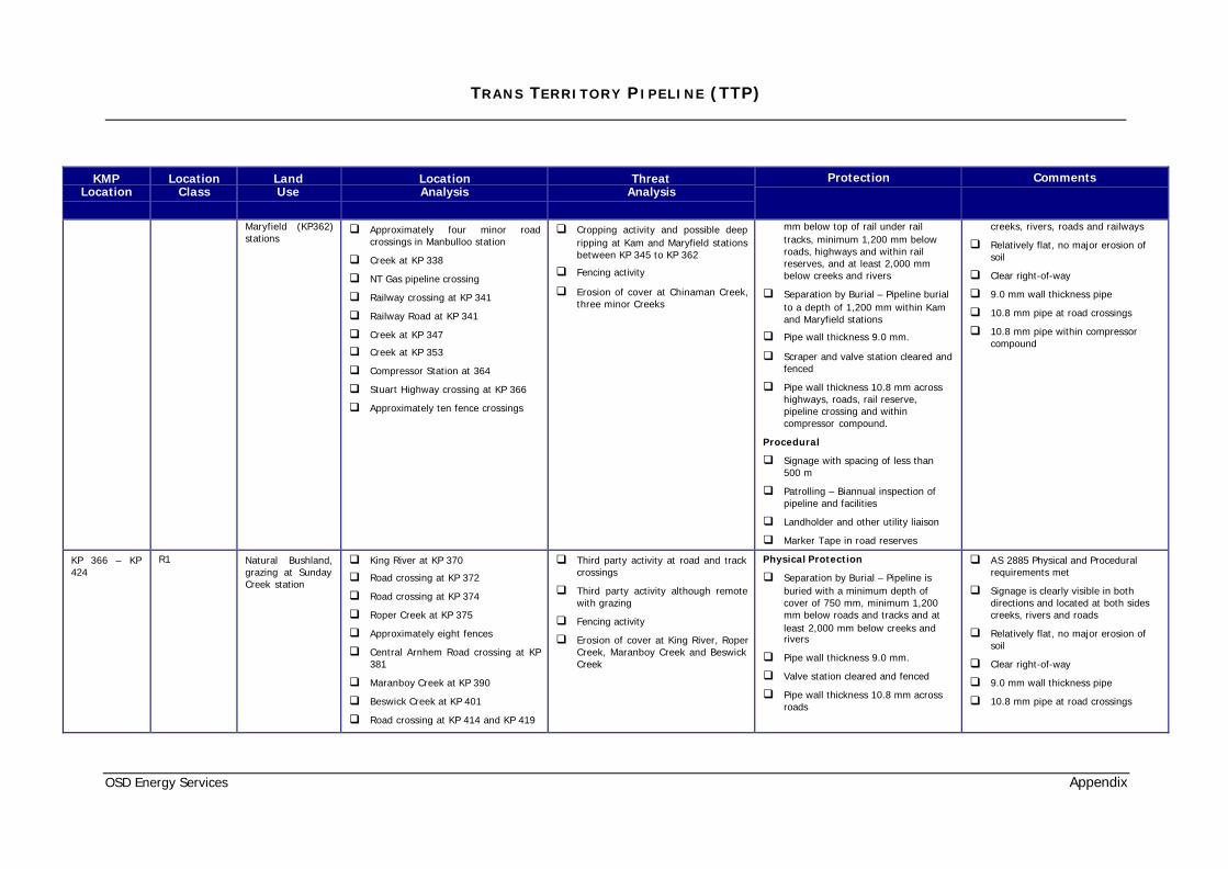
Maryfield (KP362)stations
q Approximately four minor roadcrossings in Manbulloo station
q Creek at KP 338
q NT Gas pipeline crossing
q Railway crossing at KP 341
q Railway Road at KP 341
q Creek at KP 347
q Creek at KP 353
q Compressor Station at 364
q Stuart Highway crossing at KP 366
q Approximately ten fence crossings
q Cropping activity and possible deepripping at Kam and Maryfield stationsbetween KP 345 to KP 362
q Fencing activity
q Erosion of cover at Chinaman Creek,three minor Creeks
mm below top of rail under railtracks, minimum 1,200 mm belowroads, highways and within railreserves, and at least 2,000 mmbelow creeks and rivers
q Separation by Burial – Pipeline burialto a depth of 1,200 mm within Kamand Maryfield stations
q Pipe wall thickness 9.0 mm.
q Scraper and valve station cleared andfenced
q Pipe wall thickness 10.8 mm acrosshighways, roads, rail reserve,pipeline crossing and withincompressor compound.
Procedural
q Signage with spacing of less than500 m
q Patrolling – Biannual inspection ofpipeline and facilities
q Landholder and other utility liaison
q Marker Tape in road reserves
creeks, rivers, roads and railways
q Relatively flat, no major erosion ofsoil
q Clear right-of-way
q 9.0 mm wall thickness pipe
q 10.8 mm pipe at road crossings
q 10.8 mm pipe within compressorcompound
KP 366 – KP424
R1 Natural Bushland,grazing at SundayCreek station
q King River at KP 370
q Road crossing at KP 372
q Road crossing at KP 374
q Roper Creek at KP 375
q Approximately eight fences
q Central Arnhem Road crossing at KP381
q Maranboy Creek at KP 390
q Beswick Creek at KP 401
q Road crossing at KP 414 and KP 419
q Third party activity at road and trackcrossings
q Third party activity although remotewith grazing
q Fencing activity
q Erosion of cover at King River, RoperCreek, Maranboy Creek and BeswickCreek
Physical Protection
q Separation by Burial – Pipeline isburied with a minimum depth ofcover of 750 mm, minimum 1,200mm below roads and tracks and atleast 2,000 mm below creeks andrivers
q Pipe wall thickness 9.0 mm.
q Valve station cleared and fenced
q Pipe wall thickness 10.8 mm acrossroads
q AS 2885 Physical and Proceduralrequirements met
q Signage is clearly visible in bothdirections and located at both sidescreeks, rivers and roads
q Relatively flat, no major erosion ofsoil
q Clear right-of-way
q 9.0 mm wall thickness pipe
q 10.8 mm pipe at road crossings

TRANS TERRITORY P IPELINE (TTP)
OSD Energy Services Appendix
KMPLocation
LocationClass
LandUse
LocationAnalysis
ThreatAnalysis
Protection Comments
q Buried valve station at KP 419
q Mataranka back road at KP 423
q Water House Creek at KP 424
Procedural
q Signage with spacing of less than500 m
q Patrolling – Biannual inspection ofpipeline and facilities
q Landholder and other utility liaison
q Marker Tape in road reserves
KP 424 – KP500
R1 Natural Bushland q Road crossing at KP 433
q Chambers River at KP 441 and KP444
q Bukalorkmi Creek at KP 475
q Scraper station at KP 485
q Road crossing at KP 485
q Velkerri Creek at KP 490
q Maiwok Creek at KP 500
q Approximately five fences
q Third party activity at road crossings
q Third party activity although remotewith grazing
q Fencing activity
q Possible low depth mining activityfrom KP 465 to KP 500
q Erosion of cover at Chambers River,Bukalorkmi Creek, Velkerri Creek andMaiwok Creek
Physical Protection
q Separation by Burial – Pipeline isburied with a minimum depth ofcover of 750 mm, minimum 1,200mm below roads and at least 2,000mm below creeks and rivers
q Pipe wall thickness 9.0 mm.
q Scraper station cleared and fenced
q Pipe wall thickness 10.8 mm acrossroads
Procedural
q Signage with spacing of less than500 m
q Patrolling – Biannual inspection ofpipeline and facilities
q Landholder and other utility liaison
q AS 2885 Physical and Proceduralrequirements met
q Signage is clearly visible in bothdirections and located at both sidescreeks, rivers and roads
q Undulating possible erosion of soil.Higher maintenance area.
q Clear right-of-way
q 9.0 mm wall thickness pipe
q 10.8 mm pipe at road crossings
KP 500 – KP600
R1 Natural Bushland q Multiple channels of Flying Fox Creekat KP 506
q Derim Derim Creek at KP 509
q Valve station at KP 533
q Central Arnhem Road crossing at KP535
q Ouibobikwi Creek at KP 538
q Mainoru River at KP 550
q Horse Creek at KP 570
q Third party activity at road crossing
q Third party activity although remotewith grazing
q Fencing activity
q Possible low depth mining activityfrom KP 500 to KP 545
q Erosion of cover at Flying Fox Creek,Derim Derim Creek, OuibobikwiCreek Mainoru River, Horse Creekand Wilton River
Physical Protection
q Separation by Burial – Pipeline isburied with a minimum depth ofcover of 750 mm, minimum 1,200mm below roads and at least 2,000mm below creeks and rivers
q Pipe wall thickness 9.0 mm.
q Scraper station cleared and fenced
q Pipe wall thickness 10.8 mm acrossroads
q AS 2885 Physical and Proceduralrequirements met
q Signage is clearly visible in bothdirections and located at both sidescreeks, rivers and roads
q Undulating possible erosion of soil.Higher maintenance area.
q Clear right-of-way
q 9.0 mm wall thickness pipe

TRANS TERRITORY P IPELINE (TTP)
OSD Energy Services Appendix
KMPLocation
LocationClass
LandUse
LocationAnalysis
ThreatAnalysis
Protection Comments
q Road at KP 593
q Wilton River at KP 600
q Approximately six fences
Procedural
q Signage with spacing of less than500 m
q Patrolling – Biannual inspection ofpipeline and facilities
q Landholder and other utility liaison
q Marker Tape at road reserve
q 10.8 mm pipe at road crossings
KP 600 – KP701
R1 Natural Bushland q Scraper at KP 638
q Annie Creek at KP 641 and KP 685
q Goyder River at KP 701
q Third party activity although remote
q Erosion of cover at Annie Creek andGoyder River
Physical Protection
q Separation by Burial – Pipeline isburied with a minimum depth ofcover of 750 mm and at least 2,000mm below creeks and rivers
q Pipe wall thickness 9.0 mm.
q Scraper station cleared and fenced
Procedural
q Signage with spacing of less than500 m
q Patrolling – Biannual inspection ofpipeline and facilities
q Landholder and other utility liaison
q AS 2885 Physical and Proceduralrequirements met
q Signage is clearly visible in bothdirections and located at both sidescreeks and rivers
q Relatively flat, no major erosion ofsoil
q Clear right-of-way
q 9.0 mm wall thickness pipe
KP 701 – KP804
R1 Natural Bushland q Valve station at KP 738
q Central Arnhem Road crossing at KP739
q Badalngarrmirri Creek at KP 760
q Central Arnhem Road crossing at KP770, KP 773, KP 783, and KP 785
q Buckingham River at KP 779
q Scraper station at KP 797
q Gapuwiyak Road at KP 797
q Habgood River at KP 804
q Third party activity at road crossing
q Third party activity although remote
q Erosion of cover at BadalngarrmirriCreek, Buckingham River andHabgood River
Physical Protection
q Separation by Burial – Pipeline isburied with a minimum depth ofcover of 750 mm, minimum 1,200mm below roads and at least 2,000mm below creeks and rivers
q Pipe wall thickness 9.0 mm.
q Valve and scraper station cleared andfenced
q Pipe wall thickness 10.8 mm acrossroads
Procedural
q AS 2885 Physical and Proceduralrequirements met
q Signage is clearly visible in bothdirections and located at both sidescreeks, rivers and roads
q Relatively flat, no major erosion ofsoil
q Clear right-of-way
q 9.0 mm wall thickness pipe
q 10.8 mm pipe at road crossings
TRANS TERRITORY P IPELINE (TTP)
OSD Energy Services Appendix
KMPLocation
LocationClass
LandUse
LocationAnalysis
ThreatAnalysis
Protection Comments
q Signage with spacing of less than500 m
q Patrolling – Biannual inspection ofpipeline and facilities
q Landholder and other utility liaison
q Marker Tape at Road reserves
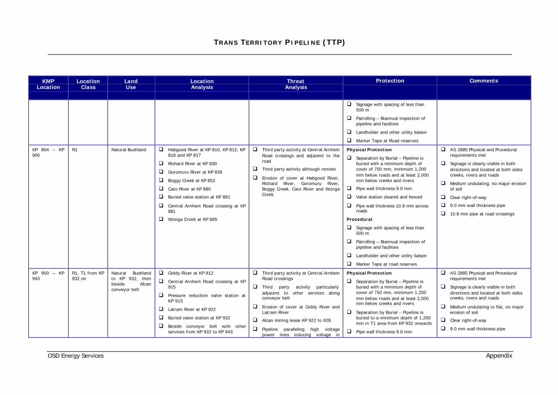
KP 804 – KP900
R1 Natural Bushland q Habgood River at KP 810, KP 812, KP816 and KP 817
q Richard River at KP 830
q Goromuru River at KP 839
q Boggy Creek at KP 852
q Cato River at KP 880
q Buried valve station at KP 881
q Central Arnhem Road crossing at KP881
q Wonga Creek at KP 895
q Third party activity at Central ArnhemRoad crossings and adjacent to theroad
q Third party activity although remote
q Erosion of cover at Habgood River,Richard River, Goromuru River,Boggy Creek, Cato River and WongaCreek
Physical Protection
q Separation by Burial – Pipeline isburied with a minimum depth ofcover of 750 mm, minimum 1,200mm below roads and at least 2,000mm below creeks and rivers
q Pipe wall thickness 9.0 mm.
q Valve station cleared and fenced
q Pipe wall thickness 10.8 mm acrossroads
Procedural
q Signage with spacing of less than500 m
q Patrolling – Biannual inspection ofpipeline and facilities
q Landholder and other utility liaison
q Marker Tape at road reserves
q AS 2885 Physical and Proceduralrequirements met
q Signage is clearly visible in bothdirections and located at both sidescreeks, rivers and roads
q Medium undulating, no major erosionof soil
q Clear right-of-way
q 9.0 mm wall thickness pipe
q 10.8 mm pipe at road crossings
KP 900 – KP943
R1, T1 from KP932 on
Natural Bushlandto KP 932, thenbeside Alcanconveyor belt
q Giddy River at KP 912
q Central Arnhem Road crossing at KP915
q Pressure reduction valve station atKP 915
q Latram River at KP 922
q Buried valve station at KP 932
q Beside conveyor belt with otherservices from KP 932 to KP 943
q Third party activity at Central ArnhemRoad crossings
q Third party activity particularlyadjacent to other services alongconveyor belt
q Erosion of cover at Giddy River andLatram River
q Alcan mining lease KP 922 to 928
q Pipeline paralleling high voltagepower lines inducing voltage in
Physical Protection
q Separation by Burial – Pipeline isburied with a minimum depth ofcover of 750 mm, minimum 1,200mm below roads and at least 2,000mm below creeks and rivers
q Separation by Burial – Pipeline isburied to a minimum depth of 1,200mm in T1 area from KP 932 onwards
q Pipe wall thickness 9.0 mm.
q AS 2885 Physical and Proceduralrequirements met
q Signage is clearly visible in bothdirections and located at both sidescreeks, rivers and roads
q Medium undulating to flat, no majorerosion of soil
q Clear right-of-way
q 9.0 mm wall thickness pipe

TRANS TERRITORY P IPELINE (TTP)
OSD Energy Services Appendix
KMPLocation
LocationClass
LandUse
LocationAnalysis
ThreatAnalysis
Protection Comments
q Beside high voltage power lines KP932 to KP 943
q Melville Bay Road crossing at KP 941
q Gate Station at KP 943
pipeline q Valve stations cleared and fenced
q Pipe wall thickness 10.8 mm in T1area from KP 932 onwards.
q Adequate earthing and surgeprotection at Gate Station
Procedural
q Signage at less than 500 metrecentres
q Signage at less than 250 metrecentres from KP 932 onwards
q Patrolling – Biannual inspection ofpipeline and facilities
q Landholder, mining lease holder andother utility liaison
q Marker Tape at road reserves
q 10.8 mm pipe at road crossings andin T1 area from KP 932 onwards

TRANS TERRITORY P IPELINE (TTP)
OSD Energy Services Appendix
APPENDIX B
TYPICAL GAS COMPOSITION

TRANS TERRITORY P IPELINE (TTP)
OSD Energy Services Appendix
Typical gas composition expected is tabulated below.
Component Composition (Mole %)
H2O 0.0153
CO2 1.1001
Nitrogen 7.3882
Methane 87.9820
Ethane 2.2892
Propane 0.7378
I Butane 0.0894
N Butane 0.1683
I Pentane 0.0490
N Pentane 0.0389
Hexanes 0.0377
Heptanes 0.0438
Octanes 0.0390
Nonanes 0.0119
Decanes 0.0075
Undecanes 0.0019
C12+ 0.0000
Total 100.0000