Report technology-in-costruction-site-the-élysée-from-mam-to-itc
44
Department of Rural Engineering INTERNSHIP REPORT “TECHNOLOGY IN CONSTRUCTION SITE” Company’s name: MEGA ASSET MANAGEMENT.CO., LTD Students’ name: THIM Mengly (e20120734) SUN Sophalraksmey (e20120696) SOPHAL Sokuntheara (e20120664) KHIM Sovima (e20120297) Project Manager: Mr. RA Boreyvuth Head of Department: Dr. LY Sarann Academic Year 2016-2017 Institut de Technologie du Cambodge Maga Asset Management.Co.,Ltd
-
Upload
thim-mengly -
Category
Engineering
-
view
9 -
download
0
Transcript of Report technology-in-costruction-site-the-élysée-from-mam-to-itc

Department of Rural Engineering
INTERNSHIP REPORT
“TECHNOLOGY IN CONSTRUCTION SITE”
Company’s name: MEGA ASSET MANAGEMENT.CO., LTD
Students’ name: THIM Mengly (e20120734)
SUN Sophalraksmey (e20120696)
SOPHAL Sokuntheara (e20120664)
KHIM Sovima (e20120297)
Project Manager: Mr. RA Boreyvuth
Head of Department: Dr. LY Sarann
Academic Year
2016-2017
Institut de Technologie du Cambodge Maga Asset Management.Co.,Ltd

Institut de Technologie du Cambodge Departement de Genie Rural
i
ACKNOWLEDGEMENTS
After completing fourth-year student of Rural Engineering of Institute of Technology
of Cambodia, the obligation is to do an internship related to our studies field and write report
acknowledgement that we go from internship. To complete our internship report properly, it is
accompany the help and support from many people who have given us permission, knowledge
financing, consulting and courage. For this reason, we would like to mention all our sincere
thanks to.
Firstly, we would like to express our deep gratitude to our parents for financial
support, advice and encouragement since we was born till now for most 20 years.
We would like to his Excellency Dr. OM Romny, director of Institute of Technology
of Cambodia. According to his authorization for doing internship in a company.
We express my sincere Dr. LY Sarann, head of the Rural Engineering Department
who has been so active and interactive with students throughout this internship program. For
all his efforts so that students can learn the technical work and what we never learned at
school.
We would like to thank to all lecturers of ITC, especially lecturers of Rural
Engineering department for giving us knowledge base that are really essential for our
professional life.
More thank to MEGA ASSET MANAGEMENT.CO., LTD who allow us to have an
opportunity to learn and practice what we’re studied at school into the real work.
We offer thank Mr. RA Boreyvuth Project Manager, Mr. SENG Youhong, site
manager and Mr. SUN Sathia Engineer Block 3.1&3.2 of Building The Elysee, who had
been really kind to us, always try to tell us about work and provide many knowledge, show
further detailed relate to varied technique of construction in site, some experiences in site
management and some designing.
Finally, we wish all of you to have a happiness life, you always stay still healthy and
successfully in your life.

Institut de Technologie du Cambodge Departement de Genie Rural
ii
ABSTRACT
This report is prepared in the purpose of getting the recommendation from the
company, MEGA ASSET MANAGEMENT.CO.,LTD, and completing the internship
obligation of Institute of Technology of Cambodia (ITC). This report is described about
conception for design some structural elements and construction technology, it’s also
prepared for studied document that can help the next generation student do research related to
construction field.

Institut de Technologie du Cambodge Departement de Genie Rural
iii
TABLES OF CONTENTS
ACKNOWLEDGEMENT ............................................................................................... i
ABSTRACT ................................................................................................................... ii
TABLES OF CONTENTS ............................................................................................ iii
LIST OF FIGURES ........................................................................................................ v
CHAPTER I: INTRODUCTION ................................................................................. 1
I. GENERAL STATEMENT ............................................................................... 1
II. PRESENTATION ............................................................................................. 1
A. Internship:...................................................................................................... 1
B. Enterprises: .................................................................................................... 1
C. Site Location of The Elysee Project: ............................................................. 2
D. Company‘s partners of The Elysee project: .................................................. 2
CHAPTER II: FOUNDATION (FOOTING) .............................................................. 3
I. Introduction ....................................................................................................... 3
A. Types of Footing ........................................................................................... 3
II. Construction of Reinforced Concrete Footing ...................................................... 4
CHAPTER III: LEAN CONCRETE ........................................................................... 7
I. Generalization ................................................................................................... 7
II. Construction of Lean Concrete ............................................................................. 7
A. Soil/Sand Compaction and Leveling ............................................................. 7
B. Installation of formwork: .............................................................................. 8
C. Pouring Concrete on Sand: ............................................................................ 8
D. Lean Concrete ............................................................................................... 8
CHAPTER IV: REINFORCED CONCRETE BASEMENT SLABS ....................... 10
I. Generalization ................................................................................................. 10
II. Conception of Designing Reinforced Concrete Basement Slab ..................... 10
III. Construction of Slabs ...................................................................................... 10
A. Installation of Formwork ............................................................................. 10
B. Pouring Reinforced Concrete of Slabs ........................................................ 10
C. Installation of Framework with Steel .......................................................... 11
D. Reinforcement of Slabs ............................................................................... 11
CHAPTER V: REINFORCED CONCRETE BASEMENT WALLS ....................... 13
I. Generalization ....................................................................................................... 13

Institut de Technologie du Cambodge Departement de Genie Rural
iv
II. Conception of Designing Reinforced Concrete Basement Wall..................... 13
III. Construction Technics in Site: ........................................................................ 13
A. Installation of Formwork ............................................................................. 13
B. Pouring Reinforced Concrete of Basement Walls....................................... 14
C. Installation with steels ................................................................................. 14
D. Reinforcement of Basement Walls .............................................................. 14
CHAPTER VI: REINFORCED CONCRETE COLUMN ........................................ 15
I. Generalization ................................................................................................. 15
II. Construction of Reinforcement concrete column ........................................... 15
A. Installing steel in column ............................................................................ 15
B. Installation of the formworks ...................................................................... 15
C. Pouring Concrete ......................................................................................... 16
D. Removing and curing reinforcement concrete of column ........................... 16
E. Pictures about Processes of Column Work ................................................. 17
CHAPTER VII: REINFORCED CONCRETE BEAMS ........................................... 18
I. Generalization ....................................................................................................... 18
II. Conception of Designing Reinforced Concrete Beams....................................... 18
III. Structural Installation of Beams ........................................................................ 19
A. Installation of Formworks ........................................................................... 19
B. Putting of beam’s steel Reinforcement ....................................................... 20
CHAPTER VIII: SECURITIES AND CONCLUSION ............................................ 21
I. Security of Site ................................................................................................ 21
II. Conclusion ...................................................................................................... 23
APPENDICES .............................................................................................................. 24
APPENDIX A: standard hooks use in site of project the Elysee ............................. 24
APPENDIX B: Standard spacing limits for reinforcements .................................... 24
APPENDIX C: Standard of concrete protection for reinforcement ........................ 25
APPENDIX D: Standard development length of Bars ............................................ 26
APPENDIX E: Standard of lap splice length .......................................................... 27
APPENDIX F: Standard Bar Arrangement ............................................................. 28
APPENDIX G: Standard of Slab and Wall ............................................................. 32
REFERENCES ............................................................................................................. 35

Institut de Technologie du Cambodge Departement de Genie Rural
v
LIST OF FIGURES
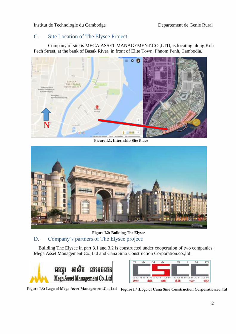
Figure I.1. Internship Site Place ..................................................................................... 2 Figure I.2: Building The Elysee ..................................................................................... 2 Figure I.3: Logo of Mega Asset Management.Co.,Ltd .................................................. 2 Figure I.4:Logo of Cana Sino Construction Corporation.co.,ltd .................................... 2 Figure II.1: Oppressing Pile ........................................................................................... 5
Figure II.2: Digging the Soil........................................................................................... 5 Figure II.3: Cutting the head pile ................................................................................... 6 Figure II.4: Installing the formwork ............................................................................... 6
Figure II.5: Installing the reinforcement......................................................................... 6 Figure II.6: Casting the concrete .................................................................................... 6 Figure II.7: Pile cap after pouring and remove formwork .......................................... 6 Figure II.8: Testing slump .............................................................................................. 6
Figure III.1: Soil Compaction and Leveling ................................................................... 7 Figure III.2: Formwork for Lean Concrete with thickness 50mm ................................. 8
Figure III.3: Pouring Lean Concrete............................................................................... 8 Figure III.4. Lean concrete under basement slab and pile cap after pouring ................. 9
Figure IV.1: Waterproofing .......................................................................................... 11 Figure IV.2: Water stop ................................................................................................ 11 Figure IV.3: Installing steel slabs ................................................................................. 11
Figure IV.4: Chair bar for save spacing from bottom bar to top bar of basement slab 11 Figure IV.5: Polish Surface of Concrete ...................................................................... 12
Figure IV.6: Pouring concrete ...................................................................................... 12 Figure IV.7: Testing Hummer ...................................................................................... 12
Figure IV.8: Wet Burlap ............................................................................................... 12 Figure V.1: Installing steels and Water stop of basement wall .................................... 14
Figure VI.1: Instilling reinforcement............................................................................ 17 Figure VI.2: Instilling formwork .................................................................................. 17 Figure VI.3: Make rough surface ................................................................................. 17
Figure VI.4: Test slump ................................................................................................ 17 Figure VI.5: Keeping for test ........................................................................................ 17 Figure VI.6: Caste concrete .......................................................................................... 17 Figure VI.7: Curing Column ........................................................................................ 17 Figure VI.8: Open Formwork ....................................................................................... 17 Figure VII.1: Formworks of beam connect to slab ....................................................... 19
Figure VII.2: Installing formworks of beam ................................................................ 19 Figure VII.3: Installing steels of beams out of formwork ............................................ 20 Figure VII.4: Steel of beam put into formwork after installation ................................. 20
Figure VIII.1: Warning signal before go into site ........................................................ 21 Figure VIII.2: Barrier for protect falling down something out of site .......................... 21 Figure VIII.3: Camera security site office and Fire extinguisher in site ...................... 22 Figure VIII.4: Hygiene System for workers in site ..................................................... 22 Figure VIII.5: Using Belt security, Using Boots and Hat security during working ..... 22
Figure VIII.6: Some Warning Signal for workers in site ............................................. 23

Institut de Technologie du Cambodge Departement de Genie Rural
1
CHAPTER I: INTRODUCTION
I. GENERAL STATEMENT
We are year fourth student, Department of Rural Infrastructure Engineering, Institute
of Technology of Cambodia (ITC).
We need to complete of an obligation after finish from senior or year fourth (During
the Vacation). This Internship makes us know a lot of knowledge from there, so in this has the
time for limiting. It has the materials that attracted us know about the theories and practices.
Therefore, this internship is very important for understanding, improvement, and getting
better. Thus, students can be developed of the both courses between theories and direct
practices. Then student can improve their capacities days by days clearly and lesson in school
have a practical activities and building site.
This internship makes the students year fourth can do works, it is directly practices in
Institute of Technology of Cambodia which has an organized them with the cooperation in
private enterprises and publics. This internship will be demanded of students should do
directly practices and working in site both enterprises.
II. PRESENTATION
We are reality this internship from 11th July to 24th September 2016. Construction site
in company of MEGA ASSET MANAGEMENT.CO., LTD
A. Internship:
Tittle of Internship : Technology in Construction Site
Period of Internship : From 11th July to 24th September,2016
Project Manager : Mr. RA Boreyvuth
Site Manager : Mr. SENG Youhong
Block Manager (Part 3.1&3.2) : Mr. SUN Sathia
Head of Department : Dr. LY Sarann
B. Enterprises:
MEGA ASSET MANAGEMENT.CO.,LTD is the best one of companies in Cambodia
that has the Head office in Phnom Penh.
Address of principle office: No.315, Preah Ang Duong (St.110), corner of
Preah Monivong (St.93),Canadia Tower, 10th Floor, SangKat Wat Phnom,
Khan Doun Penh, Phnom Penh, Cambodia
Email: [email protected]
Web: www.megaassetmanagement.co.ltd
Site: The Elysee Building at Koh Pech
Tel/Fax: (855)23 430 686
H/P: (855) 23 868 222
Institut de Technologie du Cambodge Departement de Genie Rural
2
C. Site Location of The Elysee Project:
Company of site is MEGA ASSET MANAGEMENT.CO.,LTD, is locating along Koh
Pech Street, at the bank of Basak River, in front of Elite Town, Phnom Penh, Cambodia.
D. Company‘s partners of The Elysee project:
Building The Elysee in part 3.1 and 3.2 is constructed under cooperation of two companies:
Mega Asset Management.Co.,Ltd and Cana Sino Construction Corporation.co.,ltd.
Figure I.4:Logo of Cana Sino Construction Corporation.co.,ltd
Figure I.2: Building The Elysee
Figure I.1. Internship Site Place
N
Figure I.3: Logo of Mega Asset Management.Co.,Ltd

Institut de Technologie du Cambodge Departement de Genie Rural
3
CHAPTER II: FOUNDATION (FOOTING)
I. Introduction
Reinforced concrete footings are structural members used to support columns and
walls and to transmit and distribute their loads to the soil or rock support the structural. Because the soil is generally much weaker than the concrete columns and walls that must be
supported, the contact area between the soil and the footing is much larger than that between
the supported member and the footing. The design is based on the assumption that the footing
is rigid, so that the variation of the soil pressure under the footing is linear. Uniform soil
pressure is achieved when the column load coincides with the centroid of the footing.
Although this assumption is acceptable for rigid footings, such an assumption becomes less
accurate as the footing becomes relatively more flexible. The proper design of footings
requires that:
1. The load capacity of the soil is not exceeded.
2. Excessive settlement, differential settlement, or rotations are avoided.
3. Adequate safety against sliding and/or overturning is maintained.
A. Types of Footing
Different types of footings may be used to support building columns or walls. The
most common types are as follows:
a. Wall footings are used to support structural walls that carry loads from other
floors or to support nonstructural walls. They have a limited width and a
continuous length under the wall. Wall footings may have one thickness, be
stepped, or have a sloped top.
b. Isolated, or single, footings are used to support single columns. They may be
square, rectangular, or circular. Again, the footing may be of uniform
thickness, stepped, or have a sloped top. This is one of the most economical
types of footings, and it is used when columns are spaced at relatively long
distances. The most commonly used are square or rectangular footings with
uniform thickness.
c. Combined footing usually support two columns or three columns even if not in
a row. The shape of the footing in the plan may be rectangular or trapezoidal,
depending on column loads. Combined footings are used when two columns
are so close that single footings cannot be used or when one column is located
at or near a property line.
d. Cantilever, or strap, footings consist of two single footings connected with a
beam or a strap and support two single columns. They are used when one
footing supports an eccentric column and the nearest adjacent footing lies at
quite a distance from it. This type replaces a combined footing and is
sometimes more economical.
e. Continuous footings support a row of three or more columns. They have
limited width and continue under all columns.
f. Raft, or mat, foundations consist of one footing, usually placed under the entire
building area, and support the columns of the building. They are used when
The soil-bearing capacity is low.

Institut de Technologie du Cambodge Departement de Genie Rural
4
Column loads are heavy.
Single footings cannot be used.
Piles are not used.
Differential settlement must be reduced through the entire footing system.
g. Pile caps are thick slabs used to tie a group of piles together and to support
and transmit column loads to the piles.
Properties of Footing in the Elysee Project:
Dimension: Varies
Strength: '
,28 30MPacf (Cylinder)
Steel yield strength of deformed bars: 390MPayf
Slump: 14 2cm
II.Construction of Reinforced Concrete Footing
The construction of footing has many steps. The below points are all of steps for
construction of footing.
1. Find and mark axis of piles
First of all, the surveyors need to find and mark axis of piles. We do that because we
don’t want incorrect when we hummer or oppress pile in soil. If it is incorrect, it is so difficult
to remove it. So it is a job that needs high attention.
2. Hummer or Oppress piles
When we have axis of piles already, the after job is hummer or oppress pile. In is job,
we can use oppress machine to oppress piles in the soil when the soil is not hard enough. For
contract, if the soil is so hard, we use hummer machine to hummer piles in the soil. The
oppress machine is faster and have less error than hummer machine.
3. Digging the Soil
After we hummer or oppress piles in the soil already, then we need to dig the soil out.
We do that because we want to limit the shape and the elevation of the pile cape.
4. Cutting head piles
After we dig already, we need to cut the head of piles. We do that because we want
make all of head’s piles have the same element that easy to make the pile cape.
5. Casting Lean Concrete
After we cut the head’s piles already, we need to cast the lean concrete. Lean concrete
have many advantages. It makes the worker easy walk and work.
6. Installing of formwork
The surveyor needs to mark the axis of the formwork.
We clean the structures and formwork that pile cape can be better of resistance.
The formworks can cover by ointment with little chemical production for
making smoothly. So it might be easy when we want to ruffle and don’t allow
leaking water from the formworks. It can help to fix for the water can’t across
to outside.
Then the formwork is craned by crane to keep at axis. It is craned one by one.
After then, we use steel to connect them together.
Furthermore, we need to gravity or probe 3 sides or 4 sides. We do that
because we want them to straight. We can approve if they have approximately
only 5mm of tilting.
Then we use reinforcements to tighten them together.
We mark the elevation that we want to cast arrive.

Institut de Technologie du Cambodge Departement de Genie Rural
5
After we install it already, the inspector comes to check. They straight or not. It
is according to code or not.
When they are correct, QS will order concrete to cast.
7. Installing of Reinforcement of the pile cape
We use 25 diameter of the main bar. We install it according to code that the designer
has limit.
After we install reinforcement already, the inspector will come to check our installing.
If it is wrong, we will repair it again. If it is correct by code, the installing of reinforcement is
finish.
8. Cast the Concrete
The concrete is not mix at site. They are mix already at company of concrete. We can
order lot of kind of concrete according to slump and strength. Thus, before we cast concrete,
we always check the slump. Then, we take some of concrete to test strength by calendric.
After the slump is correct, then the concrete is casted.
We use the vibration for compaction. We compact it by one layer to one layer.
We cast it until arrive the marking.
9. Remove and Cure the Pile cape
After We casted 3 or 4 days, we will remove the formwork out of column. Then we
will see that reinforced concrete of column is good or bad. It is good mean that it is not break
or steel is not out of concrete. It is bad mean that it is not break or steel is out of concrete.
Thus, if it is bad, we can develop it or fight it and cast again. But if it is good, we can cure by
use sack that wet to cover it. We do that because we want to give water to it for protect
evaporation that because it crack by shorten volume.
10. Put the water Proof
Pile cape is the structure that always locates in the soil. Thus it always affect by water
that infiltrate to it. If the water can infiltrate in it, the steel will rust that because the strength
will down. So we need to protect the water don’t come in it. The water proof is so important
to protect the infiltrate to our pile cape.
Figure II.1: Oppressing Pile Figure II.2: Digging the Soil

Institut de Technologie du Cambodge Departement de Genie Rural
6
Figure II.8: Testing slump Figure II.7: Pile cap after pouring and remove
formwork
Figure II.3: Cutting the head pile Figure II.4: Installing the formwork
Figure II.5: Installing the reinforcement Figure II.6: Casting the concrete

Institut de Technologie du Cambodge Departement de Genie Rural
7
CHAPTER III: LEAN CONCRETE
I. Generalization
The Lean Concrete is a surface of concrete structure that situated under all of
structural element such as ground slab, pile cap or all structure that connected to soil. Lean
Concrete is cleaner between sedimentary and soil. So when are putting of lean that we are put
which chemical substances and plastics.
Using material such as machine vibration, sand, formwork, crushed stone, water,
cement and plastics.
Furthermore, lean is supporter on charges none only permanence but it can a variable,
and supporter due to beam that be binding on the columns. Lean is has a thickness 50mm with
concrete that we create this floor for stocker of merchandises, equipment so on.
II. Construction of Lean Concrete
The construction of lean is the same from slab that mean another slabs are equivalent
first floor or second floor. But it is little a bit difference of the formworks:
Dimension of lean concrete in site The Elysee are:
Thickness: 50mm
Slump : 14 ± 2 cm
No Reinforcing
In this site Lean Concrete use two types: under pile caps and basement slab.
A. Soil/Sand Compaction and Leveling
After Foundation work (cutting piles and pile capes) we prepared to fill up and to level
the soil by using Mini Roller that follow plan of project and level that define by group of
surveyors.
Figure III.1: Soil Compaction and Leveling

Institut de Technologie du Cambodge Departement de Genie Rural
8
B. Installation of formwork:
The formwork are installed only the sides. Then, we are putting the chemical
substances is protected insects. We use formwork with wooden.
C. Pouring Concrete on Sand:
We are putting the sand on coarse
Compacted soil/sand follow level that define by plan by
using machine mini roller and by water
Utilization chemical products for protecting of insects.
Cover by using the plastics with one day
Mini roller compacts on the sand
D. Lean Concrete
We are following this step that’s correct all sites. They are always acquire the
concrete products come from other companies. Thus, when site orders concrete from
company it is easy to pouring and gains the money and times. So it is convenience of pouring
concrete directly in the site. During Lean Concrete, we used to use machine for a display of
great splendor and magnificence. Our concretes that are from part to part with slope of the
Figure III.3: Pouring Lean Concrete
Figure III.2: Formwork for Lean Concrete with thickness 50mm

Institut de Technologie du Cambodge Departement de Genie Rural
9
plat. Utilization of vibrator did not actually forgotten due to it has very important of
compacter in concrete and makes a concrete is homogeneous for reinforce the resistance of
pouring Lean Concrete. Lean Concrete have created by keep up the stocker something, so we
are using a type of chemical products for protecting on only moreover can make a concrete is
smooth and beauty of Lean Concrete.
The part of chemical product is liquid mean that very important for making a concrete
easy to compaction and homogeneity. After that, concrete is lately insensitive, we use another
machine for compaction again. Lastly, when concrete has an unimpressionable with stone and
sand, we need to protect of the rain or something that across it. For method protection of rain,
we can use the plastic for cover on the Lean Concrete.
Figure III.4. Lean concrete under basement slab and pile cap after pouring

Institut de Technologie du Cambodge Departement de Genie Rural
10
CHAPTER IV: REINFORCED CONCRETE BASEMENT SLABS
I. Generalization
Basement concrete slabs are constructed to provide flat surfaces, usually horizontal, in
building floors, and other types of structures. The basement slab may be supported by the
ground. The depth of a basement slab is usually very small compared to its span.
When we are putting of slab that we are put which reinforce concrete and putting the
steels 25mm, and wire for tie. Using material such as machine vibration, versing meter, and
steels so on.
Furthermore, basement slab is stayed on the soil, if lean concrete layer is considered as
part of basement slab. In addition to drainage, a waterproofing or damp-proofing membrane
must be laid or applied to the construction.
Dimension of Slabs are:
Thickness 500mm
Strength 30MPa (Cylinder)
Slump 14+2cm
II. Conception of Designing Reinforced Concrete Basement Slab
The condition under which the moment coefficients for continuous beams and slabs
should be used can be summarized as follows:
Spans are approximately equal: Longer span ≤ 1.2 (shorter span).
Loads are uniformly distributed.
The ration (live load and dead load) is less than or equal to 3.
For slabs with spans less than or equal to 3.3m, negative banding moment at
face of all supports is (1/12) Wu l2
n.
For an unrestrained discontinuous end at A, the coefficient is 0 at A and
(+1/11) at B.
Shearing force at C is (1.15 Wu ln /2) and at the face of all the support is (Wu ln
/2).
Mu = (Coefficient) (Wu l2n) and ln= Clear span.
III. Construction of Slabs
The construction of basement slab is the same from lean, but it is little a bit difference
of the formworks:
A. Installation of Formwork
The formworks are installed as whole side. Then, we are putting the steels of 25mm,
and tie of wire. Put the both steels between top and bottom. We use formwork with wooden.
B. Pouring Reinforced Concrete of Slabs
We are preparing the waterproofing or damp-proofing membrane.
We are putting the formworks at the whole side.
Using sponge for putting into the hole formwork for protection the leakage of
concrete.

Institut de Technologie du Cambodge Departement de Genie Rural
11
water stop
C. Installation of Framework with Steel
After we have installed formwork of basement already, it is very important that we can
put the steel with respective in the plan. Then, before we are putting steel in the basement
slab, we must specify detail of calculation. All steel are haute adherence. The framework with
steel were punch there are two layers with bar and haute couture are allowed for designing.
The steels, we did choose already mean that’s correct with plan and site. Tie of the steels are
directly put in plane on the Site. We ought to keep a higher 5cm that is for supporting and
protecting of the part tortuous.
We are putting the bottom steel layer first before the second steel layer by
using the chair bar for support the top bar layer, too.
Checking of elevation slab’s thickness (using the level machine).
The point that is very important is must punch and put are plumbing systems.
D. Reinforcement of Slabs
We are allowing this step that’s correct all of site. They are always acquire the
concrete products come from other companies. Thus, when site order reinforced concrete
from company it is easy to pouring and gains the money and time. So it is convenience of
pouring concrete directly in the site. During Reinforced Concrete of Basement Slab, we used
to use machine for a display of great splendor and magnificence. Our concrete is from part to
part with slope of the plat. Utilization of vibrator did not actually forgotten due to it has very
important of compacter in concrete and makes a concrete is homogenize for reinforce the
resistance of pouring Reinforced Concrete of Basement Slab.
Figure IV.1: Waterproofing
Figure IV.4: Chair bar for save spacing from
bottom bar to top bar of basement slab Figure IV.3: Installing steel slabs
Figure IV.2: Water stop

Institut de Technologie du Cambodge Departement de Genie Rural
12
Reinforced Concrete of Basement Slab has created by keep up the stocker something,
so we are using a type of steel products for preventing of tortuous in the structure, on only
moreover can make a reinforced concrete is smooth and beauty of Reinforced Concrete of
Basement Slab.
The part of steels products are types of beauty of steels mean that very important for
making a reinforced concrete easy to compaction and homogeneity. After that, reinforced
concrete is poured in this slab so before pouring we need test slump of reinforced concrete
whatever we are appropriately received from company.
Figure IV.6: Pouring concrete
Figure IV.7: Testing Hummer
Figure IV.5: Polish Surface of Concrete
Figure IV.8: Wet Burlap

Institut de Technologie du Cambodge Departement de Genie Rural
13
CHAPTER V: REINFORCED CONCRETE BASEMENT WALLS
I.Generalization
Basement walls in buildings may be designed as propped cantilever walls subjected to
earth pressure and vertical loads. This case occurs only if the first-floor slab has been
constructed.
A surcharge of 9.576×10⁻⁵MPa may be adopted. When the wall only has been built on
top of the basement floor slab, the wall will be subjected to lateral earth pressure with no
vertical loads except its own weight. The wall in this case acts as a cantilever, and adequate
reinforcement should be provided for a cantilever wall design. This case can be avoided by
installing the basement and the first-floor slabs before backfilling against the wall.
In addition to drainage, a waterproofing or damp-proofing membrane must be laid or
applied to the external face of the wall.
II. Conception of Designing Reinforced Concrete Basement Wall
The ACI Code, Chapter 11, provides methods for bearing wall design. The main
requirements are as follows:
1. The minimum thickness of bearing walls is 1/25 the supported height or length,
whichever is shorter, but not less than 10cm.
2. The minimum area of the horizontal reinforcement in the wall is 0.0025bh, where bh is
the gross concrete wall area. This value may be reduced to 0.0020bh if no. 5 or smaller
deformed bars with fy ≥ 413.685MPa are used. For welded wire fabric (plain or
deformed), the minimum steel area is 0.0020bh.
3. The minimum area of the vertical reinforcement is 0.0015bh, but it may be reduced to
0.0012bh if no. 5 or smaller deformed bars with fy ≥ 413.685MPa are used. For welded
wire fabric (plain or deformed), the minimum steel area is 0.0012bh.
4. The maximum spacing of the vertical or the horizontal reinforcing bars is the smaller of
46cm. or three times the wall thickness.
5. If the wall thickness exceeds 25cm., the vertical and horizontal reinforcement should be
placed in two layers parallel to the exterior and interior wall surfaces, as follows: For
exterior wall surfaces, at least 1/2 of the reinforcement As (but not more than 2/3As)
should have a minimum concrete cover of 5cm. but not more than 1/3 of the wall
thickness. This is because the exterior surface of the wall is normally exposed to
different weather conditions and temperature changes.
For interior wall surfaces, the balance of the required reinforcement in each direction
should have a minimum concrete cover of 2cm. but not more than 1/3 of the wall thickness.
III. Construction Technics in Site:
A. Installation of Formwork
There is the type of formwork:
Formwork with of wooden
We lie of formwork with wooden in using the nails. During construction of beams, we
have installed like supports slaps of the building .But in this site, we use only formwork
wooden.

Institut de Technologie du Cambodge Departement de Genie Rural
14
B. Pouring Reinforced Concrete of Basement Walls
We are preparing the waterproofing or damp-proofing membrane.
We are putting the formworks at the whole side.
Using sponge for putting into the hole formwork for protection the leakage
of concrete.
C. Installation with steels
After we have installed formwork at the side already, it is very important that we can
put the steel with respective in the plan. Then, before we are putting steel in the basement
wall, we must specify detail of calculation. All steel are haute adherence. The framework with
steel were punch there are two layers with bar and haute couture are allowed for designing.
The steels, we did choose already mean that’s correct with plan and site. Tie of the steels are
directly put in plane on the Site. We ought to keep a higher 5cm that is for supporting and
protecting of the part tortuous.
We are putting the exterior steel layer first before the interior steel layer.
Checking the thickness of Basement Wall.
The point that is very important is must punch and put are waterproofing or
damp-proofing membrane systems.
D. Reinforcement of Basement Walls
For Basement Wall, we are allowing this step that’s correct all of site. They are always
acquire the concrete products come from other companies. Thus, when site order reinforced
concrete from company it is easy to pouring and gains the money and time. So it is
convenience of pouring concrete directly in the site. During Reinforced Concrete of Basement
Wall, we used to use machine for a display of great splendor and magnificence. We have done
it during the Basement Columns.
Install with steel
Water Stop
Figure V.1: Installing steels and Water stop of basement wall

Institut de Technologie du Cambodge Departement de Genie Rural
15
CHAPTER VI: REINFORCED CONCRETE COLUMN
I. Generalization
Column is an element vertical that supports all of element of the building such: slaps,
beam, roofs and material use in building. It is strength with compression, traction, and
bending. The more general terms compression members and member subjected to combined
axial load and bending are sometimes used to refer to column.
It is very important material that uses for transmitting all loads from building to pile
cape. Column has many shapes like: rectangular, cycle, and square. The cross-sectional
dimensions of columns are generally considerably less than its height.
Column has two types are long column or slender column and short column.
Short column is the column that have ratio of effect length to the least lateral
dimensions of the column is less than 12 or we can say when the ratio of effective length to
the least radius of the gyration is less than 45. For contrast, long column or slender column is
the column that when the ratio of the effective length to the least radius of gyration is greater
than 45.
II. Construction of Reinforcement concrete column
A. Installing steel in column
After we install pile cape already, we will have some reinforcements that we install
from the bottom of the pail cape. Then we will take transversal reinforcements to keep in
them in order to making easy to use when we apply longitudinal reinforcement or main bar.
After that, we take longitudinal reinforcement to connect with them. After we install already
according to plan, then transversal reinforcements are installed. At my site, I use diameter of
main bar and stirrup . .
Column properties:
Dimension : Varies
Strength: 35 MPa ( cylinder)
Slump: 14±2 cm
B. Installation of the formworks
After we instill reinforcement already, then the inspector come to check. If the
reinforcement is correct by code. Then the surveyor will project to find axis of formwork.
After we have axis of formwork, the formworks will make already at site. They can be use
wooden and steel.
First, we clean the structures and formwork that column can be better of
resistance.
The formworks can cover by ointment with little chemical production for
making smoothly. So it might be easy when we want to ruffle and don’t allow
leaking water from the formworks. It can help to fix for the water can’t across
to outside.
Then the formwork is craned by crane to keep at axis. It is craned one by one.
After then, we use steel to connect them together.
1025

Institut de Technologie du Cambodge Departement de Genie Rural
16
Furthermore, we need to gravity or probe 3 sides or 4 sides. We do that
because we want them to straight. We can approve if they have approximately
only 5mm of tilting.
Then we use reinforcements to tighten them together.
We mark the elevation that we want to cast arrive.
After we install it already, the inspector comes to check. They straight or not. It
is according to code or not.
When they are correct, QS will order concrete to cast.
C. Pouring Concrete
The concrete is not mix at site. They are mix already at company of concrete. We can
order lot of kind of concrete according to slump and strength. Thus, before we cast concrete,
we always check the slump. Then, we take some of concrete to test strength by calendric.
After the slump is correct, then the concrete is casted.
We use the vibration for compaction. We compact it by one layer to one layer.
We cast it until arrive the marking.
D. Removing and curing reinforcement concrete of column
After We casted 3 or 4 days, we will remove the formwork out of column. Then we
will see that reinforced concrete of column is good or bad. It is good mean that it is not break
or steel is not out of concrete. It is bad mean that it is not break or steel is out of concrete.
Thus, if it is bad, we can develop it or fight it and cast again. But if it is good, we can cure by
use sack that wet to cover it. We do that because we want to give water to it for protect
evaporation that because it crack by shorten volume.

Institut de Technologie du Cambodge Departement de Genie Rural
17
E. Pictures about Processes of Column Work
Figure VI.3: Make rough
surface Figure VI.1: Instilling
reinforcement Figure VI.2: Instilling formwork
Figure VI.6: Caste concrete Figure VI.5: Keeping for test Figure VI.4: Test slump
Figure VI.8: Open Formwork Figure VI.7: Curing Column

Institut de Technologie du Cambodge Departement de Genie Rural
18
CHAPTER VII: REINFORCED CONCRETE BEAMS
I. Generalization
The reinforced concrete beams are studying the sections of the best one resistance of
flexion, and it can support horizontal endorsement with wooden, metals, and reinforced
concrete. Beams are reinforced element of the building that can apply directly the vertical.
The reinforced concrete beams can support by columns and wall. So principle beam could be
support of adjoining beams.
Properties of Beams in Project The Elysee:
Dimension :(varied)
Strength : 30MPa (Cylinder)
Slump : 14+2cm
II. Conception of Designing Reinforced Concrete Beams
For analysis and design of a structural member may be regarded as the process of
selecting the proper materials and determining the member of dimension such that the design
strength is equal or greater than required strength.
Beams are design an assumptions such as strain in concrete is the same as in
reinforcing bars at the same level, provided that the bond between the steel and concrete is
adequate. Strain in concrete is linearly proportional to the distance from the neutral axis. The
modulus of elasticity of all grades of steel is Es = 200000 MPa. Plane cross-sections continue
to be plane after bending. Tensile strength of concrete shall be neglected in axial and flexural
calculations of reinforced concrete. Maximum usable strain at extreme concrete compression
fiber shall be assumed equal to εs = 0.003.
1. Design Section
This beam is T sections with compression reinforcement that is used when:
Beam dimension are limited by architecture
To reduce long term deflection
Hold stirrups to resist shear
But two cases of doubly concrete reinforcement are considered:
When compression steel yields
When compression steel does not yield.
2. Advantages
This beam is created by construction for reinforcement steels of columns so that
foundation of building has a lot floors. Therefore, before pouring to foundation we should be
thought of the quality soil. After we had done foundation that we go on applies the columns.
When columns are finishing that it can be applies to beam very important because it can
support the slab and everything that stocks.
Beams are very important of the buildings that can distributions of the charges as a
whole building. Furthermore, beam is distributed by humongous on each beam of the
building. Therefore, it is excellence method in among another that can prevent improved
beam of building by the columns.

Institut de Technologie du Cambodge Departement de Genie Rural
19
III. Structural Installation of Beams
After we have the foundation and columns, we can commence to construct of principle
beams and sub-beams. All of steels structure that has the transversal and longitudinal steels is
prepared in the site. After we have done installation steels in the principle beams and sub-
beam that are correct positions as following to projectors that given the plans of principle
beam and sub-beam. Moreover, workers are tying all of structures in each beam. It has the
same bloc tie of structural concrete for structural correcting and the formworks. Then, the site
engineer does observe the works and installation of the structure, finding some errors for do
again or remove to tie steels and putting of longitudinal steels, tie transversal before pouring
of the reinforced concrete.
A. Installation of Formworks
There is the type of formwork:
Formwork with of wooden
We lie of formwork with wooden in using the nails. During construction of beams, we
have installed like supports slaps of the building .But in this site, we use only formwork
wooden.
Figure VII.1: Formworks of beam connect to slab
Figure VII.2: Installing formworks of beam

Institut de Technologie du Cambodge Departement de Genie Rural
20
B. Putting of beam’s steel Reinforcement
We are putting of beam’s steel reinforcement the both between top bars and bottom
bars. Let just say top bars and bottom bars are related to the main bars, so these bars we can
add one more bars in that can call temperature bars. Very important points that we don’t
forget is when connecting bars, about measure is 40 of dimension multiple of the section.
Where link connection is top bars don’t connecting nearly column and for linking connection
is bottom bars don’t connecting direct in the middle point beam structural.
That why can not to connect nearly column about main bars mean top bars, because of
those points are doing the moment too, so we can’t to connect initial of beams. That why we
can’t to connect middle point of beam structure about bottom bar. Because bottom bars are
doing the moment.
Actually, we must put the temperature bars cause this bars very important that it can
be prevented the compression nearly columns.
Figure VII.3: Installing steels of beams out of formwork
Figure VII.4: Steel of beam put into formwork after installation

Institut de Technologie du Cambodge Departement de Genie Rural
21
CHAPTER VIII: SECURITIES AND CONCLUSION
I. Security of Site
The security of site is prepared obligations for life. The process of work is peaceful
places without high risk of accidents and dangers. Therefore, site manager has a higher
responsibility and control us every time but also have an individual responsibility. Actually,
site is the best place that makes me have a reality for obtaining better securities as following:
We must do the auto barriers of site for a voiding all of risk and all of people
in site.
There are engineer securities in the site.
The engines of site are good controlling.
The hates, gloves, jackboots, and belts are distributed of cover during engineer
of scraps and the site reinforced concrete.
The scaffolds are auto good installation of site for avoiding of the chutes and
choosing of horizon in the site.
Connecting of tubes around the building
Store for keeping of tools
Figure VIII.1: Warning signal before go into site
Figure VIII.2: Barrier for protect falling down something out of site

Institut de Technologie du Cambodge Departement de Genie Rural
22
Figure VIII.5: Using Belt security, Using Boots and Hat security during working
Figure VIII.3: Camera security site office and Fire extinguisher in site
Figure VIII.4: Hygiene System for workers in site

Institut de Technologie du Cambodge Departement de Genie Rural
23
II. Conclusion
During two and half months, for internship makes us know better about school lessons
and we can obtain a lot of experiences and knowledge in site as following:
Read plan of structure
Work on the columns, lean concrete, principle beams, adjoining beams, slabs
and especially reinforced concrete.
Management works in site as:
Manage of number workers size in working and times
Manage of materials for working
Resolution of problems that are obstacle in working
Supply and keep on the materials
Knowing of means for finding in site and for doing works.
We trained for two month in our vocation MEGA ASSET
MANAGEMENT.CO.,LTD. All days in the maintenance practices in the generator field
make us know what real work besides just realize the theories. In our internships, most of our
work is working on the field and study about the technology of building construction. We can
achieve some what We do not know before. We are very happy that we can successfully
complete this internship for two and half months.
Figure VIII.6: Some Warning Signal for workers in site

Institut de Technologie du Cambodge Departement de Genie Rural
24
APPENDICES
APPENDIX A: standard hooks use in site of project the Elysee
APPENDIX B: Standard spacing limits for reinforcements

Institut de Technologie du Cambodge Departement de Genie Rural
25
APPENDIX C: Standard of concrete protection for reinforcement

Institut de Technologie du Cambodge Departement de Genie Rural
26
APPENDIX D: Standard development length of Bars

Institut de Technologie du Cambodge Departement de Genie Rural
27
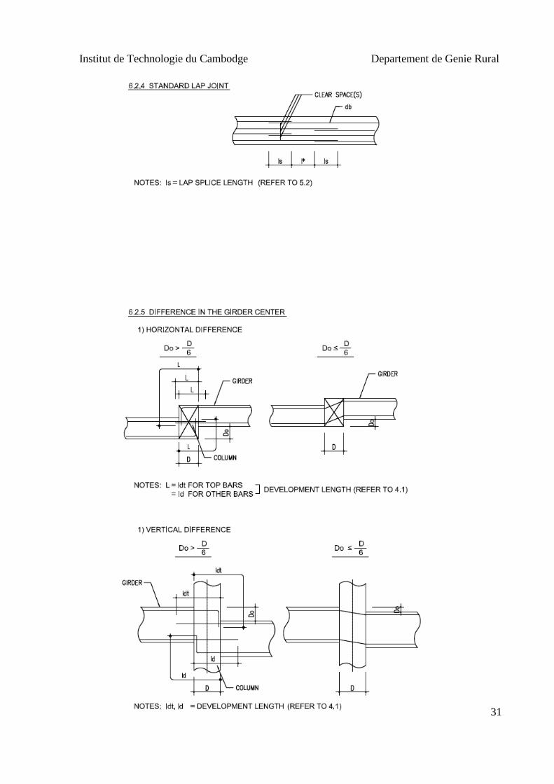
APPENDIX E: Standard of lap splice length

Institut de Technologie du Cambodge Departement de Genie Rural
28
APPENDIX F: Standard Bar Arrangement

Institut de Technologie du Cambodge Departement de Genie Rural
29

Institut de Technologie du Cambodge Departement de Genie Rural
30
Institut de Technologie du Cambodge Departement de Genie Rural
31

Institut de Technologie du Cambodge Departement de Genie Rural
32
APPENDIX G: Standard of Slab and Wall

Institut de Technologie du Cambodge Departement de Genie Rural
33

Institut de Technologie du Cambodge Departement de Genie Rural
34

Institut de Technologie du Cambodge Departement de Genie Rural
35
REFERENCES
1. Structural Concrete, Theory and Design, Sixth Edition. Nadim Hassoun, South Dakota
State University, Akthem Al-Manaseer, San Jose State University, 2015
2. Reinforcement Concrete Mechanics & Design six edition )
3. An ACI Standard, Building Code Requirements for Structural Concrete (ACI 318M-
14) and Commentary (ACI 318RM-14),Reported by ACI Committee 318
4. Building Code Requirements for Structural Concrete (ACI 318M-05) and
Commentary (ACI 318RM-05),Reported by ACI Committee 318
5. Ouvrages en Beton Arme,Technologie du Batiment-Gros Oeuvre,H. Renaud.
6. Foundation Analysis and Design, Joseph E. Bowles, P.E., S.E fifth edition.

CONTRACTOR :
THE ELYSEE
PILE CAPS PLAN 3.1 & 3.2
SCALE 1:450

70
2.4
0
40
50
10
0
2.00
50
1.7
0
50
1.00
1.00
2.4
0
2.4
02
.4
0
40
50
1.0
0
2.00
50
2.4
0
1.00
1.00
3.4
03
.8
0
5.5
0
7.2
0
1.7
0
7.2
0
BASEMENT WALL & B2 DETAIL 1:50
6-11-2014
Mr.Vong Sokun
SCALE
DRAWING NO.
FILE :
DATE: TOTAL
APPROVED:
CHECKED:
DRAWN:
DRAWING TITLE:
DATEREVISIONS
SANITARY ENGINEERS
Mr.Ra Boreyvuth
STRUCTURAL ENGINEERS
MECHANICAL ENGINEERS
ELECTRICAL ENGINEERS
ARCHITECTS
CONSTRUCTION
Phnom Penh
WORKING DRAWING
-
PROJECT MANAGER
Cambodia
Mr.Yin Virak
-
Mr.Ky Piseth
FOR CONSTRUCTION
Mr.Ky Piseth
Mr.Ky Piseth
Mr.Touch Samnang
DEPUTY CEO (OCIC)
Mr.Ra Boreyvuth
KEYPLAN
Mr.Tieng Samphors
MEGA ASSET MANAGEMENT
Mr.Hok Bunleang
Mr.Tieng Samphors
JOB NO.
Phnom Penh Cambodia
.\Koh Pich.bmp
OWNER
THE ELYSEE
Mr.Souk Daravuth
S:047
BASEMENT WALL , B2 DETAIL
SCALE 1:50

11 11 11 11 11 11 11 11 11 11 11 11
11 11 11 11 11 11 11 11 11 11 11 11
11
11
11
11
11
11
11
11
11
11
9 9 9 9 910 10 10 10 10
9 9 9 9 910 10 10 10 10
9
10
10
10
99
11 11 11 11 11 11 11 11 11 11 11 11
11 11 11 11 11 11 11 11 11 11 11 11
11
11
11
11
11
11
11
11
11
11
24 24 24 24 2423 23 23 23 23
24
23
23
24
24
23
24 24 24 24 2423 23 23 23 23
SECTION A-A
1000
600
25
19DB10@150
27
19DB10@150
28
19DB10@150
29
19DB10@150
C35, 34DB25+26DB20
SECTION C-C
1000
25
3DB10@150
27
3DB10@150
28
3DB10@150
29
3DB10@150
25
19DB10@150
100
1
0
0
940
540
940
5
4
0
27
19DB10@150
100
1
0
0
777
540
777
5
4
0
28
19DB10@150
100
1
0
0
289
540
289
5
4
0
29
19DB10@150
100
1
0
0
940
375
940
3
7
5
600
11 11 11 11 11 11 11 11 11 11 11 11
11 11 11 11 11 11 11 11 11 11 11 11
11
11
11
11
11
11
11
11
11
11
9 9 9 9 910 10 10 10 10
9 9 9 9 910 10 10 10 10
9
10
10
10
99
SECTION B-B
1000
600
25
23DB10@150
27
23DB10@150
28
23DB10@150
29
23DB10@150
26
19DB10@150
26
23DB10@150
26
3DB10@150
26
19DB10@150
80
8
0
940
BEAM 1B8
(400x800)
50
5S
TR
+1LIN
K-20D
B10@
150
50
800
2850
3100
COLUMN DETAIL C35 (GRID 05, 06 & C63~67, C71~C73)
1200
1000
400
1000
1000
11 34DB25
10 13DB25
9 13DB25
24 13DB20
23 13DB20
1000
23 13DB20
3000
24 13DB20
4000
11 34DB25
1050
1
5
4
6802
10 13DB25
1050
1
5
4
5552
9 13DB25
1050
1
5
4
4552
CONST
JOINT
0.50 +
6.70 -
05
B1 SLABB1 SLAB
50
5S
TR
+1LIN
K-23D
B10@
150
3.10 -
250
3300
25
150
8000
25
150
6750
25
150
5750
A A
CONST
JOINT
C C
B B
4100
7200
50
06
CONTRACTOR :
THE ELYSEE