REFRIGERANT RECOVERY MACHINE - Javac
24
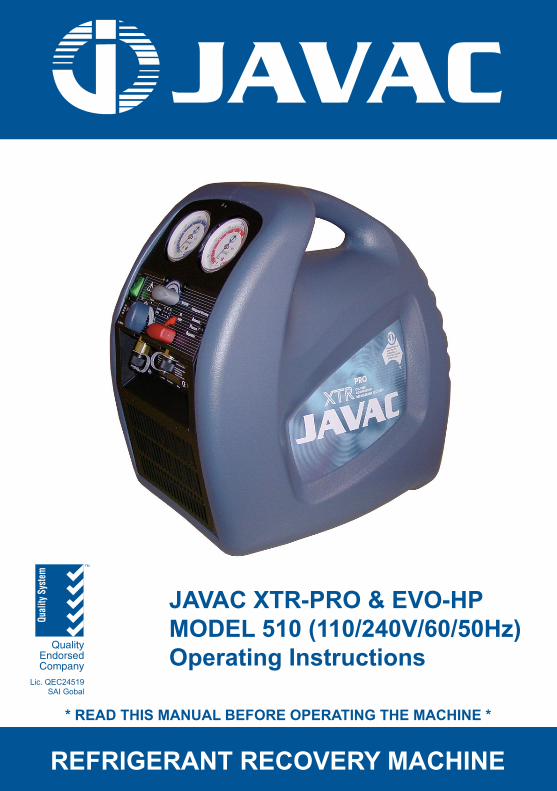
JAVAC XTR-PRO & EVO-HP MODEL 510 (110/240V/60/50Hz) Operating Instructions REFRIGERANT RECOVERY MACHINE * READ THIS MANUAL BEFORE OPERATING THE MACHINE * Quality System Quality Endorsed Company TM Lic. QEC24519 SAI Gobal
Transcript of REFRIGERANT RECOVERY MACHINE - Javac
COMMERCIAL & LABORATORY VACUUM PUMPS
CS Series
CD Series
JL Series
JLT Series
JAVAC XTR-PRO & EVO-HPMODEL 510 (110/240V/60/50Hz)Operating Instructions
REFRIGERANT RECOVERY MACHINE
* READ THIS MANUAL BEFORE OPERATING THE MACHINE *
Qua
lity
Sys
tem
QualityEndorsedCompany
TM
Lic. QEC24519SAI Gobal
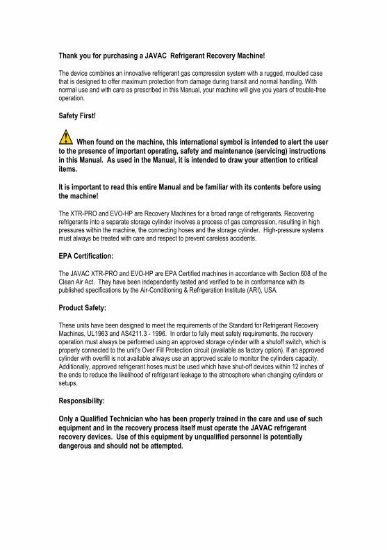
Thank you for purchasing a JAVAC Refrigerant Recovery Machine!
The device combines an innovative refrigerant gas compression system with a rugged, moulded case that is designed to offer maximum protection from damage during transit and normal handling. With normal use and with care as prescribed in this Manual, your machine will give you years of trouble-free operation.
Safety First!
When found on the machine, this international symbol is intended to alert the user to the presence of important operating, safety and maintenance (servicing) instructions in this Manual. As used in the Manual, it is intended to draw your attention to critical items.
It is important to read this entire Manual and be familiar with its contents before using the machine!
The XTR-PRO and EVO-HP are Recovery Machines for a broad range of refrigerants. Recovering refrigerants into a separate storage cylinder involves a process of gas compression, resulting in high pressures within the machine, the connecting hoses and the storage cylinder. High-pressure systems must always be treated with care and respect to prevent careless accidents.
EPA Certification:
The JAVAC XTR-PRO and EVO-HP are EPA Certified machines in accordance with Section 608 of the Clean Air Act. They have been independently tested and verified to be in conformance with its published specifications by the Air-Conditioning & Refrigeration Institute (ARI), USA.
Product Safety:
These units have been designed to meet the requirements of the Standard for Refrigerant Recovery Machines, UL1963 and AS4211.3 - 1996. In order to fully meet safety requirements, the recovery operation must always be performed using an approved storage cylinder with a shutoff switch, which is properly connected to the unit's Over Fill Protection circuit (available as factory option). If an approved cylinder with overfill is not available always use an approved scale to monitor the cylinders capacity. Additionally, approved refrigerant hoses must be used which have shut-off devices within 12 inches of the ends to reduce the likelihood of refrigerant leakage to the atmosphere when changing cylinders or setups.
Responsibility:
Only a Qualified Technician who has been properly trained in the care and use of such equipment and in the recovery process itself must operate the JAVAC refrigerant recovery devices. Use of this equipment by unqualified personnel is potentially dangerous and should not be attempted.
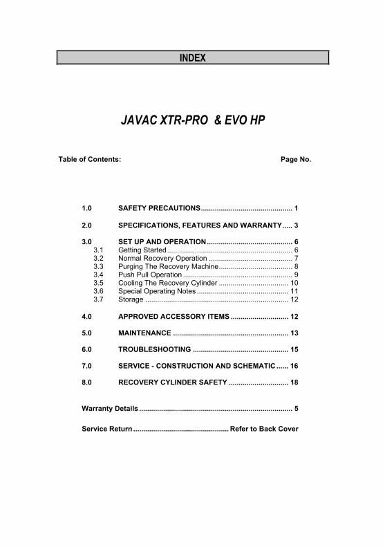
INDEX
JAVAC XTR-PRO & EVO HP
Table of Contents: Page No.
1.0 SAFETY PRECAUTIONS.............................................. 1
2.0 SPECIFICATIONS, FEATURES AND WARRANTY..... 3
3.0 SET UP AND OPERATION........................................... 6 3.1 Getting Started............................................................... 6 3.2 Normal Recovery Operation .......................................... 7 3.3 Purging The Recovery Machine..................................... 8 3.4 Push Pull Operation ....................................................... 9 3.5 Cooling The Recovery Cylinder ................................... 10 3.6 Special Operating Notes .............................................. 11 3.7 Storage ........................................................................ 12
4.0 APPROVED ACCESSORY ITEMS ............................. 12
5.0 MAINTENANCE .......................................................... 13
6.0 TROUBLESHOOTING ................................................ 15
7.0 SERVICE - CONSTRUCTION AND SCHEMATIC...... 16
8.0 RECOVERY CYLINDER SAFETY .............................. 18
Warranty Details ............................................................................. 5
Service Return ................................................ Refer to Back Cover
1
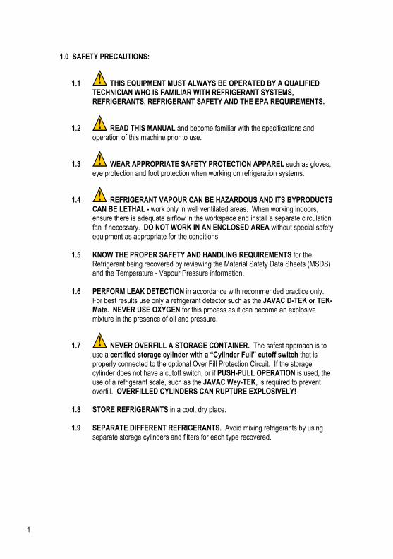
1.0 SAFETY PRECAUTIONS:
1.1 THIS EQUIPMENT MUST ALWAYS BE OPERATED BY A QUALIFIED TECHNICIAN WHO IS FAMILIAR WITH REFRIGERANT SYSTEMS, REFRIGERANTS, REFRIGERANT SAFETY AND THE EPA REQUIREMENTS.
1.2 READ THIS MANUAL and become familiar with the specifications and operation of this machine prior to use.
1.3 WEAR APPROPRIATE SAFETY PROTECTION APPAREL such as gloves, eye protection and foot protection when working on refrigeration systems.
1.4 REFRIGERANT VAPOUR CAN BE HAZARDOUS AND ITS BYPRODUCTS CAN BE LETHAL - work only in well ventilated areas. When working indoors, ensure there is adequate airflow in the workspace and install a separate circulation fan if necessary. DO NOT WORK IN AN ENCLOSED AREA without special safety equipment as appropriate for the conditions.
1.5 KNOW THE PROPER SAFETY AND HANDLING REQUIREMENTS for the Refrigerant being recovered by reviewing the Material Safety Data Sheets (MSDS) and the Temperature - Vapour Pressure information.
1.6 PERFORM LEAK DETECTION in accordance with recommended practice only.For best results use only a refrigerant detector such as the JAVAC D-TEK or TEK-Mate. NEVER USE OXYGEN for this process as it can become an explosive mixture in the presence of oil and pressure.
1.7 NEVER OVERFILL A STORAGE CONTAINER. The safest approach is to use a certified storage cylinder with a “Cylinder Full” cutoff switch that is properly connected to the optional Over Fill Protection Circuit. If the storage cylinder does not have a cutoff switch, or if PUSH-PULL OPERATION is used, the use of a refrigerant scale, such as the JAVAC Wey-TEK, is required to prevent overfill. OVERFILLED CYLINDERS CAN RUPTURE EXPLOSIVELY!
1.8 STORE REFRIGERANTS in a cool, dry place.
1.9 SEPARATE DIFFERENT REFRIGERANTS. Avoid mixing refrigerants by using separate storage cylinders and filters for each type recovered.

2
1.10 OPEN SERVICE OR CYLINDER VALVES SLOWLY to ensure that all connections are tight and there is no danger.
1.11 DISCONNECT POWER before moving or servicing the recovery unit. CAUTION - these units should be opened only by a technically qualified person who has been trained in basic electronics and refrigeration. The risk of ELECTRIC SHOCK and exposure to HOT compressor parts is possible if the unit is opened.
1.12 WARNING - TO REDUCE THE RISK OF FIRE, EXTENSION CORDS SHOULD NOT BE USED with this equipment as the wiring can overheat under conditions of high current draw. If an extension cord is absolutely necessary, its length should be as short as possible and it should contain size 16 AWG (1.291 mm) or larger wiring.
1.13 FLAMMABLE ENVIRONMENTS ARE DANGEROUS when any machine is used because motors and switches can generate sparks. This equipment should be used in locations with mechanical ventilation providing at least four air changes per hour, or the equipment should be located at least 18” above the floor. DO NOT USE THIS EQUIPMENT IN THE VICINITY OF SPILLED OR OPEN CONTAINERS OF GASOLINE OR ANY OTHER FLAMMABLE LIQUID.
1.14 MOISTURE can cause severe damage when introduced to the internal parts of a refrigeration system. Ensure that care is exercised in the leak detection, recovery, repair and refilling of a system to prevent moisture from entering. Always use a quality high vacuum pump such as JAVAC Shark/Deluxe to ensure the system is totally dehydrated. An electronic total pressure gauge such as the Acravac should also be used to monitor the pressure.
1.15 USE CAUTION WHEN OPERATING OUTDOORS. Be certain that the power cord, the cylinder safety cord and the unit itself are not placed in water or other potentially dangerous locations. While these recovery machines are very safe to operate, using in environments such as hard rain or sand and dust storms should be avoided.
1.16 CAUTION - EXERCISE CARE WHEN MOVING the equipment to prevent the risk of injury.
3
2.0 SPECIFICATIONS, FEATURES AND WARRANTY
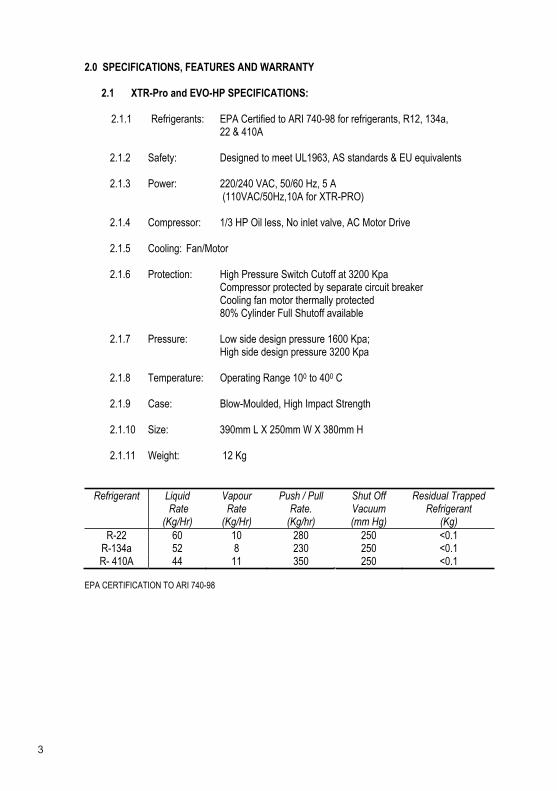
2.1 XTR-Pro and EVO-HP SPECIFICATIONS:
2.1.1 Refrigerants: EPA Certified to ARI 740-98 for refrigerants, R12, 134a, 22 & 410A
2.1.2 Safety: Designed to meet UL1963, AS standards & EU equivalents
2.1.3 Power: 220/240 VAC, 50/60 Hz, 5 A (110VAC/50Hz,10A for XTR-PRO)
2.1.4 Compressor: 1/3 HP Oil less, No inlet valve, AC Motor Drive
2.1.5 Cooling: Fan/Motor
2.1.6 Protection: High Pressure Switch Cutoff at 3200 Kpa Compressor protected by separate circuit breaker Cooling fan motor thermally protected 80% Cylinder Full Shutoff available
2.1.7 Pressure: Low side design pressure 1600 Kpa; High side design pressure 3200 Kpa
2.1.8 Temperature: Operating Range 100 to 400 C
2.1.9 Case: Blow-Moulded, High Impact Strength
2.1.10 Size: 390mm L X 250mm W X 380mm H
2.1.11 Weight: 12 Kg
Refrigerant Liquid Rate
(Kg/Hr)
VapourRate
(Kg/Hr)
Push / Pull Rate.
(Kg/hr)
Shut Off Vacuum(mm Hg)
Residual Trapped Refrigerant
(Kg)R-22 60 10 280 250 <0.1
R-134a 52 8 230 250 <0.1 R- 410A 44 11 350 250 <0.1
EPA CERTIFICATION TO ARI 740-98
4
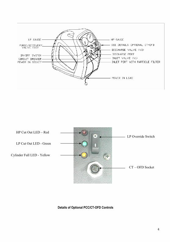
Details of Optional PCC/CT-OFD Controls
Cylinder Full LED - Yellow
HP Cut Out LED – Red
LP Cut Out LED - Green
LP Override Switch
CT – OFD Socket
5
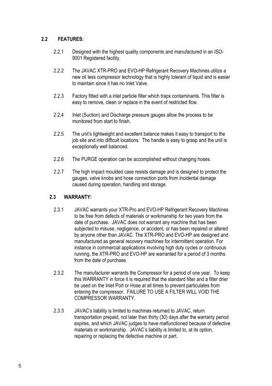
2.2 FEATURES:
2.2.1 Designed with the highest quality components and manufactured in an ISO-9001 Registered facility.
2.2.2 The JAVAC XTR-PRO and EVO-HP Refrigerant Recovery Machines utilize a new oil less compressor technology that is highly tolerant of liquid and is easier to maintain since it has no Inlet Valve.
2.2.3 Factory fitted with a inlet particle filter which traps contaminants. This filter is easy to remove, clean or replace in the event of restricted flow.
2.2.4 Inlet (Suction) and Discharge pressure gauges allow the process to be monitored from start to finish.
2.2.5 The unit’s lightweight and excellent balance makes it easy to transport to the job site and into difficult locations. The handle is easy to grasp and the unit is exceptionally well balanced.
2.2.6 The PURGE operation can be accomplished without changing hoses.
2.2.7 The high impact moulded case resists damage and is designed to protect the gauges, valve knobs and hose connection ports from incidental damage caused during operation, handling and storage.
2.3 WARRANTY:
2.3.1 JAVAC warrants your XTR-Pro and EVO-HP Refrigerant Recovery Machines to be free from defects of materials or workmanship for two years from the date of purchase. JAVAC does not warrant any machine that has been subjected to misuse, negligence, or accident, or has been repaired or altered by anyone other than JAVAC. The XTR-PRO and EVO-HP are designed and manufactured as general recovery machines for intermittent operation. For instance in commercial applications involving high duty cycles or continuous running, the XTR-PRO and EVO-HP are warranted for a period of 3 months from the date of purchase.
2.3.2 The manufacturer warrants the Compressor for a period of one year. To keep this WARRANTY in force it is required that the standard filter and a filter drier be used on the Inlet Port or Hose at all times to prevent particulates from entering the compressor. FAILURE TO USE A FILTER WILL VOID THE COMPRESSOR WARRANTY.
2.3.3 JAVAC’s liability is limited to machines returned to JAVAC, return transportation prepaid, not later than thirty (30) days after the warranty period expires, and which JAVAC judges to have malfunctioned because of defective materials or workmanship. JAVAC’s liability is limited to, at its option, repairing or replacing the defective machine or part.
6
2.3.4 This WARRANTY is in lieu of all other warranties, express or implied, whether of MERCHANTABILITY or of FITNESS FOR A PARTICULAR PURPOSE or otherwise. All such other warranties are expressly disclaimed. JAVAC practices continuous product research and improvement. We reserve the right to change specifications and product design without notice. Such revisions do not entitle the buyer to corresponding changes, improvements, additions or replacements for previously purchased equipment.
2.3.5 JAVAC shall have no liability in excess of the price paid to JAVAC for the machine plus return transportation charges prepaid. JAVAC shall have no liability for any incidental or consequential damages. All such liabilities are EXCLUDED.
3.0 SETUP AND OPERATION:
3.1 GETTING STARTED:
3.1.1 CAUTION: Only personnel who have been properly trained in the use and operation of Refrigeration Systems, Refrigerants and Service Equipment should operate this equipment. Failure to follow proper safety precautions could result in personal injury or death.
3.1.2 CAUTION: Review the full contents of this Manual before attempting to use the recovery machine in actual service.
3.1.3 Identify the refrigerant to be recovered and prepare the recovery unit for use by installing an approved filter, hoses and optional shutoff cable or scale per the diagram below. Refer to Section 4.0 of this Manual for approved accessories.
3.1.4 Connect the AC Power cord to a circuit that is protected by a 4 amp breaker.Use an extension cord only when absolutely necessary to perform the service; be sure it is the minimum length required, that it contains a safety ground wire and that it contains wires sized 16 AWG (1.291 mm) or larger.
3.1.5 Make sure the recovery unit is set in a stable position and that it is reasonably level; observe all safety precautions previously noted. Ensure that the fan inlet and discharge areas on both sides of the machine are clear from obstructions.
3.1.6 Check all connections to ensure they are tight before starting the Recovery Operation.
3.1.7 The XTR-PRO and EVO-HP are liquid tolerant recovery machines. It is important to remember to START the machine before opening the INLET valve. Should the compressor start to ‘Knock’, close the INLET valve immediately and while it is still running, slowly open the valve back again.
7
3.1.8 Use a Refrigerant Scale to ensure that the cylinder is not filled to more than 80% of its capacity by weight. When operating in the NORMAL RECOVERY or PUSH-PULL mode without the cylinder shutoff it is possible to overfill the cylinder. If you are not sure check the cylinder weight before transporting. Refer to Section 8.0 of this Manual. OVERFILLED CYLINDERS CAN RUPTURE EXPLOSIVELY!
3.2 NORMAL RECOVERY OPERATION
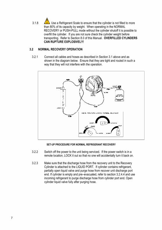
3.2.1 Connect all cables and hoses as described in Section 3.1 above and as shown in the diagram below. Ensure that they are tight and routed in such a way that they will not interfere with the operation.
SET-UP PROCEDURE FOR NORMAL REFRIGERANT RECOVERY
3.2.2 Switch off the power to the unit being serviced. If the power switch is in a remote location, LOCK it out so that no one will accidentally turn it back on.
3.2.3 Make sure that the discharge hose from the recovery unit to the Recovery Cylinder is attached to the LIQUID PORT. If cylinder contains refrigerant, partially open liquid valve and purge hose from recover unit discharge port end. If cylinder is empty and pre–evacuated, refer to section 3.2.4.4 and use incoming refrigerant to purge discharge hose from cylinder port end. Open cylinder liquid valve fully after purging hose.
8
3.2.4 Set the recovery unit for RECOVERY.
3.2.4.1 OPEN DISCHARGE valve (V3) to its fully open position.
3.2.4.2 SET PURGE/RECOVERY valve (V2) to RECOVERY position.
3.2.4.3 Open the Manifold Gauge VAPOUR valve slowly and verify that no leaks are present. Open vapour valve fully and partially open liquid valve. Do not attempt to recover 100% liquid
3.2.4.4 At this point use incoming refrigerant to purge hose.
3.2.5 Switch ON the recovery unit and verify that the compressor is operating and cooling air is exhausting from the back of the machine.
3.2.6 MONITOR the inlet pressure (LP, Low Pressure Gauge) and SLOWLY OPEN the recovery unit INLET valve (V1) fully. If the compressor ‘knocks’ shut V1 immediately, then close manifold liquid valve. Open V1 while the machine is running and continue to recover in vapour phase.
3.2.7 Continue to operate until the required VACUUM has been pulled on the system (refer to Section 8.0 of this Manual), as indicated by the LP gauge. Switch OFF the recovery unit, CLOSE the INLET (V1), and wait for 5 minutes.If the Pressure in the system, as indicated on the Manifold Gauge, rises above 0 Kpa, refrigerant is still present. If so, RESTART Recovery Machine, REOPEN the INLET (V1) and run until the required VACUUM is reached again. Repeat this process until all the refrigerant is removed resulting in a final reading of 0 Kpa or less.
3.2.8 TERMINATE the RECOVERY operation.
3.2.8.1 CLOSE Manifold Gauge Liquid and Vapor valves.
3.2.8.2 CLOSE XTR-Plus or EVO-HP INLET Valve (V1).
3.2.8.3 Switch POWER OFF.
3.2.8.4 It is a good practice to purge the Recovery Machine after each use. Refer to section 3.3 of this manual.
3.3 PURGING the recovery unit
3.3.1 While the recovery machine is running, rotate INLET Valve (V1) to CLOSE position.
3.3.2 Rotate PURGE/RECOVERY valve (V2) to PURGE position. Leave DISCHARGE (V3) open.
3.3.3 Slowly rotate Inlet V1 to PURGE position.

9
3.3.4 Observe LP Gauge and continue to run the unit until a VACUUM is achieved.Switch POWER OFF and CLOSE the Recovery Cylinder valve. Return INLET valve (V1) to CLOSE position and close V3.
3.3.5 IMPORTANT – Return V2 to RECOVERY Position
3.3.6 CAUTION - THE DISCHARGE PORT AND HOSE WILL CONTAIN A SMALL AMOUNT OF REFRIGERANT UNDER PRESSURE. EXERCISE CARE WHEN REMOVING THIS HOSE AND OPENING V3 VALVE.
SET-UP PROCEDURE FOR PURGE
3.3.7 REMOVE all hoses and cables and prepare the machine and the recovery cylinder for transport.
3.3.8 When changing refrigerants or reconnecting to a cylinder always purge the hoses and the recovery machines ports with refrigerant, (or evacuate lines), to prevent air entering the recovery process.
3.4 PUSH PULL OPERATION
3.4.1 The PUSH PULL method is used to move a large amount of liquid refrigerant from the system being serviced to the recovery cylinder without passing it through the compressor. This method is only useful when more than 7 Kg of liquid is known to be in the system and it can be easily isolated. DO NOT ATTEMPT the PUSH PULL process unless you are sure of the situation.

10
3.4.2 Connect the refrigerant hoses as shown below. Addition of a SIGHT GLASS in line between the system being serviced and the recovery cylinder is an important aid to determine when all the liquid has been transferred and only vapour remains.
3.4.3 This process uses the PULL from the exhausted recovery cylinder and the Discharge PUSH from the recovery unit to move the liquid refrigerant. Rates in excess of 5 Kg per minute can be achieved by this procedure.
3.4.4 The SCALE is required in this process to ensure that the cylinder is not overfilled. The cylinder shutoff switch, if used, would stop the compressor but could not guarantee that additional refrigerant flow would cease because of the dynamics of the system, thus possibly overfilling the cylinder.
SET-UP PROCEDURE FOR PUSH-PULL METHOD
3.5 COOLING THE RECOVERY CYLINDER
3.5.1 The recovery unit can be used to PRE-cool (or SUB-cool) the recovery cylinder if the head pressure is too high to complete the recovery process.This can occur when working with certain refrigerants with a high vapour pressure in high ambient temperatures.
3.5.2 If the recovery process stalls out because of high head pressure, stop the recovery unit, shut off the hose valves and reconfigure the setup as shown below. This can also be done before starting the recovery process but it may have marginal long term effect. NOTE: This will only work if there is at least 5 Kg of liquid in the recovery cylinder to develop the necessary pressure differential required.
11
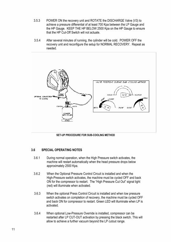
3.5.3 POWER ON the recovery unit and ROTATE the DISCHARGE Valve (V3) to achieve a pressure differential of at least 700 Kpa between the LP Gauge and the HP Gauge. KEEP THE HP BELOW 2500 Kpa on the HP Gauge to ensure that the HP Cut-Off Switch will not actuate.
3.5.4 After several minutes of running, the cylinder will be cold. POWER OFF the recovery unit and reconfigure the setup for NORMAL RECOVERY. Repeat as needed.
SET-UP PROCEDURE FOR SUB-COOLING METHOD
3.6 SPECIAL OPERATING NOTES
3.6.1 During normal operation, when the High Pressure switch activates, the machine will restart automatically when the head pressure drops below approximately 2500 Kpa.
3.6.2 When the Optional Pressure Control Circuit is installed and when theHigh-Pressure switch activates, the machine must be cycled OFF and back ON for the compressor to restart. The “High Pressure Cut Out” signal light (red) will illuminate when activated.
3.6.3 When the optional Press Control Circuit is installed and when low pressure switch activates on completion of recovery, the machine must be cycled OFF and back ON for compressor to restart. Green LED will illuminate when LP is activated.
3.6.4 When optional Low-Pressure Override is installed, compressor can be restarted after LP CUT-OUT activation by pressing the black switch. This will allow to achieve a further vacuum beyond the LP cutout range.

12
3.6.5 When optional Cylinder/Tank Overfill Protection Device is installed and if the CT-OFD Cable is not connected or Cylinder/Tank is full, the yellow “Cylinder Full” signal light will be illuminated. When this is the case, the compression will start briefly if the power is cycled OFF and ON again but will not run for more than a few seconds. This is normal operation.
3.7 STORAGE
3.7.1 When the recovery process has been completed, carefully coil the Power Cord, the Refrigerant Hoses and the Cylinder Overfill Protection Cord (if used), ensuring that no dirt or foreign material is left in the ends or on the connectors.
3.7.2 Place the recovery unit in the service vehicle in its upright position and store the hoses and cords nearby. Provide reasonable care to place the unit where it will not be subjected to accidental damage due to shifting items during transit or to heavier objects being placed on its top.
3.7.3 The unit can be stored safely in temperatures of 00 - 500 C and humidity levels up to 95% RH. When stored in conditions that are severe, the unit may need to stabilize in the range 100 - 400C before it will offer optimum operating performance. For best results, store the unit in an environmentally controlled area when not in use.
3.7.4 Always purge and vent the machine prior to storage, close V1 & V3 and leave V2 in the Recover Position.
4.0 APPROVED ACCESSORY ITEMS
4.1 The XTR-PRO and EVO-HP Refrigerant Recovery Machines require the proper accessory items to ensure the best performance. The following items are specifically identified to ensure safety and operational requirements are met. Check with your Wholesaler to ensure that the proper selections have been made.
4.1.1 REFRIGERANT HOSES should be made with approved materials, should be as short as possible to perform the required operations and should have shut-off devices within 300mm of the ends. Approved hoses are: Refrigerant Hoses with UL Recognition and 20000 Kpa Burst Strength
4.1.2 RECOVERY CYLINDERS should be approved and have an appropriate pressure rating for the refrigerant being recovered. Choose the size (normally 20 or 60 Kg) that is right for the job, and be sure they have a cylinder full float switch. Approved cylinders are:
Refrigerant cylinders with Brad Harrison 3 pin connectors
13
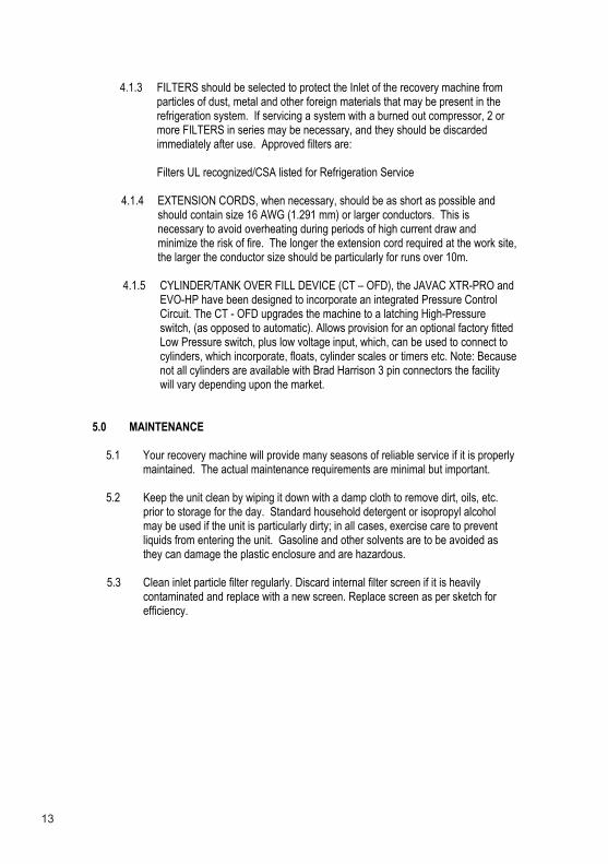
4.1.3 FILTERS should be selected to protect the Inlet of the recovery machine from particles of dust, metal and other foreign materials that may be present in the refrigeration system. If servicing a system with a burned out compressor, 2 or more FILTERS in series may be necessary, and they should be discarded immediately after use. Approved filters are:
Filters UL recognized/CSA listed for Refrigeration Service
4.1.4 EXTENSION CORDS, when necessary, should be as short as possible and should contain size 16 AWG (1.291 mm) or larger conductors. This is necessary to avoid overheating during periods of high current draw and minimize the risk of fire. The longer the extension cord required at the work site, the larger the conductor size should be particularly for runs over 10m.
4.1.5 CYLINDER/TANK OVER FILL DEVICE (CT – OFD), the JAVAC XTR-PRO and EVO-HP have been designed to incorporate an integrated Pressure Control Circuit. The CT - OFD upgrades the machine to a latching High-Pressure switch, (as opposed to automatic). Allows provision for an optional factory fitted Low Pressure switch, plus low voltage input, which, can be used to connect to cylinders, which incorporate, floats, cylinder scales or timers etc. Note: Because not all cylinders are available with Brad Harrison 3 pin connectors the facility will vary depending upon the market.
5.0 MAINTENANCE
5.1 Your recovery machine will provide many seasons of reliable service if it is properly maintained. The actual maintenance requirements are minimal but important.
5.2 Keep the unit clean by wiping it down with a damp cloth to remove dirt, oils, etc. prior to storage for the day. Standard household detergent or isopropyl alcohol may be used if the unit is particularly dirty; in all cases, exercise care to prevent liquids from entering the unit. Gasoline and other solvents are to be avoided as they can damage the plastic enclosure and are hazardous.
5.3 Clean inlet particle filter regularly. Discard internal filter screen if it is heavily contaminated and replace with a new screen. Replace screen as per sketch for efficiency.

14
5.4 Ensure that the Inlet and Discharge ports are protected and kept clean by replacing the plastic caps after every use. For best results, keep a FILTER permanently connected to the INLET port and change it regularly.
5.5 Change HOSES periodically as they develop leaks and a build-up of contaminants over time. Change hoses at least once per season.
5.6 When storing the recovery machine for the season, or for long periods of time, PURGE the unit with an inert gas such as Nitrogen.
5.7 When performance falls off it is likely that the compressor seals require replacing.This is normal with use and may occur after a year or two or more often, depending upon the conditions that are prevalent during the recovery operations. Contact your Wholesaler for assistance in selecting the proper maintenance kit.
15
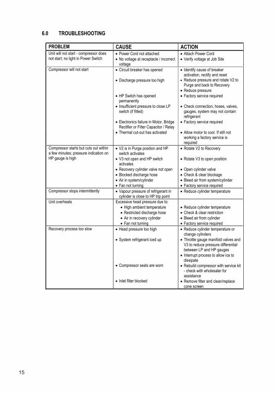
6.0 TROUBLESHOOTING
PROBLEM CAUSE ACTION Unit will not start - compressor does not start; no light in Power Switch
Power Cord not attached No voltage at receptacle / incorrect voltage
Attach Power Cord Verify voltage at Job Site
Compressor will not start Circuit breaker has opened
Discharge pressure too high
HP Switch has opened permanently Insufficient pressure to close LP switch (if fitted)
Electronics failure in Motor, Bridge Rectifier or Filter Capacitor / Relay
Identify cause of breaker activation, rectify and reset Reduce pressure and rotate V2 to Purge and back to RecoveryReduce pressure Factory service required
Check connection, hoses, valves, gauges, system may not contain refrigerant Factory service required
Thermal cut-out has activated Allow motor to cool. If still not working a factory service is required
Compressor starts but cuts out within a few minutes; pressure indication on HP gauge is high
V2 is in Purge position and HP switch activates V3 not open and HP switch activatesRecovery cylinder valve not open Blocked discharge hose Air in system/cylinder Fan not turning
Rotate V2 to Recovery
Rotate V3 to open position
Open cylinder valve Check & clear blockage Bleed air from system/cylinder Factory service required
Compressor stops intermittently Vapour pressure of refrigerant in cylinder is close to HP trip point
Reduce cylinder temperature
Unit overheats Excessive head pressure due to: High ambient temperature Restricted discharge hose Air in recovery cylinder Fan not turning
Reduce cylinder temperature Check & clear restriction Bleed air from cylinder Factory service required
Recovery process too slow Head pressure too high
System refrigerant iced up
Compressor seals are worn
Inlet filter blocked
Reduce cylinder temperature or change cylinders Throttle gauge manifold valves and V3 to reduce pressure differential between LP and HP gauges Interrupt process to allow ice to dissipateRebuild compressor with service kit - check with wholesaler for assistanceRemove filter and clean/replace cone screen
16
7.0 SERVICE - CONSTRUCTION AND SCHEMATIC
7.1 SERVICE
7.1.1 The XTR-PRO and EVO-HP use only UL, CSA or TUV recognized electrical components or components which have been specially designed for this application.
7.1.2 DO NOT CHANGE any of these components as the safety of the machine could be compromised. All service work must be performed at a JAVAC approved facility in order to maintain the safety rating and the Warranty, if applicable.
7.1.3 Technical assistance and service information can be obtained by calling the factory at AUS 1300 786 771. UK (01642)-232-880 or the Organization where you purchased the recovery machine
NOTE: Do not return a defective unit directly to the factory. Contact your Wholesaler or the factory for assistance.
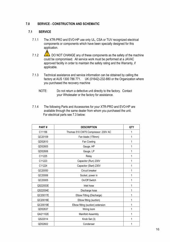
7.1.4 The following Parts and Accessories for your XTR-PRO and EVO-HP are available through the same dealer from whom you purchased the unit.
For electrical parts see 7.3 below:
PART # DESCRIPTION QTYC11156 Thomas 510 CW75 Compressor: 230V AC 1
QC20109 Fan blade (178mm) 1 QD52610 Fan Cowling 1 QD52605 Gauge, HP 1 QD52606 Gauge, LP 1 C11225 Relay 1 C11223 Capacitor (Run) 230V 1 C11224 Capacitor (Start) 230V 1
QC20050 Circuit breaker 1 QC20006 Socket, power in 1 QC20005 On/Off Switch 1
QS22053E Inlet hose 1 QS22054E Discharge hose 1 QC20017E Elbow Fitting (Discharge) 1 QC20018E Elbow fitting (suction) 1 QC20019E Elbow fitting (suction) extension 1 QD52637 Wiring loom 1
QA21102E Manifold Assembly 1 QS22014 Knob Set (3) 1 QD52602 Condenser 1
17
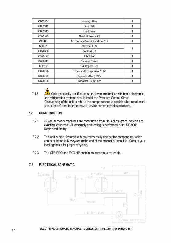
QD52654 Housing - Blue 1 QD52612 Base Plate 1 QD52613 Front Panel 1 QS22020 Manifold Service Kit 1 C11441 Compressor Seal Kit for Model 510 1 R50631 Cord Set AUS
QC20056 Cord Set UK 1
QS20127 Inlet Filter 1 QC20011 Pressure Switch 1 D52882 1/4" Copper Pipe 1
QC20128 Thomas 510 compressor 110V 1 QC20129 Capacitor (Start) 110V 1 QC20130 Capacitor (Run) 110V 1
7.1.5 Only technically qualified personnel who are familiar with basic electronics and refrigeration systems should install the Pressure Control Circuit. Disassembly of the unit to rebuild the compressor or to provide other repair work should be referred to an approved service center as indicated above.
7.2 CONSTRUCTION
7.2.1 JAVAC recovery machines are constructed from the highest-grade materials to exacting standards. All assembly and testing is performed in an ISO-9001 Registered facility.
7.2.2 This unit is manufactured with environmentally compatible components, which can be substantially recycled at the end of the product’s useful life. Consult your local agencies for proper recycling.
7.2.3 The XTR-PRO and EVO-HP contain no hazardous materials.
7.3 ELECTRICAL SCHEMATIC
ELECTRICAL SCHEMATIC DIAGRAM - MODELS XTR-Plus, XTR-PRO and EVO-HP
18
8.0 RECOVERY CYLINDER SAFETY
8.1 Recovery Cylinders are tested to specific requirements to ensure that they will be safe during the transportation process. These requirements ensure the safety of the cylinder when it is filled to an appropriate level and when it is exposed to elevated temperatures, as in a truck or on a hot day outside.
8.2 However, a cylinder that is overfilled may still be unsafe, even though the rating is acceptable for the particular refrigerant. It is therefore extremely important, as noted in Sections 1 and 3 of this Manual, to ensure that the cylinder is not overfilled.
8.3 The cylinder must not be filled beyond 80% of its capacity. If a scale is to be used, this weight can be determined by taking 80% of the Water Capacity (WC) weight that is marked on the cylinder and adding that to the Tare Weight (TW) of the cylinder. The TW is also marked on the cylinder.
8.4 If the cylinder is partially filled and the TW is unknown, then the following MAXIMUM TOTAL weights should be used for the recovery process using the weigh scale:
22 Kg Cylinder - Fill to 28Kg, Total Maximum Weight 65 Kg Cylinder - Fill to 75Kg Total Maximum Weight

19
THANK YOU FOR SUPPORTING AN AUSTRALIAN COMPANY
JAVAC PTY LTD

* IMPORTANT INFORMATION *
ONLY JAVAC KNOW HOW TO SERVICE YOUR VACUUM PUMP!
SERVICE SUPPORTWARRANTY CLAIMSREPAIRSTECHNICAL ADVICEIMMEDIATE ATTENTION
CALL JAVAC – 1300 786 771 For details on shipping direct to JAVAC.
Don’t Trust “Just Any One” With Your Vacuum Pump. You will receive fast, friendly service, but more importantly, speak to the people who designed and manufactured your vacuum pump and who have the technical expertise to keep it in action!
JAVAC Pty LtdCorporate and Facility contact details
dtLWSNCAVAJeciffOdaeHteertSruhtrA951/91teertSeladhsuR45
WSNtseWhsubemoHairotciVdleifxonKailartsuA0412ailartsuA0813
Ph: +61 (0) 3 9763 7633 Ph: +61 (0) 2 9746 3536Fax: +61 (0) 3 9763 2756 Fax: +61 (0) 2 9746 2714e-mail: [email protected] e-mail: [email protected]
dnalaeZweNCAVAJeporuECAVAJecalPtiaT7,DtinUdetimiL)KU(cavaJ
dnalkcuAynablAtruoCekarD6tinUBritannia Park Middlesbrough New ZealandTS2 1 RS United Kingdom Ph: +64 (0) 9 479 6960 Ph: +44 (0) 1642-232-880 Fax: +64 (0) 9 479 3769Fax: +44 (0) 1642-232-870 e-mail: [email protected]: [email protected]: www.javac.co.uk
For more information on products or technical assistance visit our website:
www.javac.com.au
Part No. C11275Issue: August 2007
Website: www.javac.co.nz
Part No. C11275Issue: September 2008