Refrigerant Management System 37880 Manual - YELLOW...
16
Automatic Refrigerant Recovery/Recycling/Recharge System Operation Manual 37880/37881/37882/37887/37888/37889 37880 Series YELLOW JACKET ®
Transcript of Refrigerant Management System 37880 Manual - YELLOW...
Automatic Refrigerant Recovery/Recycling/Recharge System
Operation Manual 37880/37881/37882/37887/37888/37889
37880 Series
YELLOW JACKET ®
2
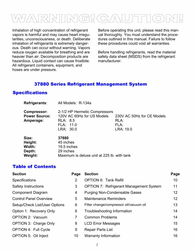
Refrigerants: All Models: R-134a Compressor: 2-1/2 HP Hermetic Compressors Power Source: 120V AC 60Hz for US Models 230V AC 50Hz for CE Models Amperage: RLA: 8.5 RLA: FLA: 11.0 FLA: LRA: 30.0 LRA: 19.0 Size: 37880 Height: 45 inches Width: 19.5 inches Depth: 29 inches Weight: Maximum is deluxe unit at 225 lb. with tank
Before operating this unit, please read this man-ual thoroughly. You must understand the proce-dures outlined in this manual. Failure to follow these procedures could void all warranties. Before handling refrigerants, read the material safety data sheet (MSDS) from the refrigerant manufacturer.
Inhalation of high concentration of refrigerant vapors is harmful and may cause heart irregu-larities, unconsciousness, or death. Deliberate inhalation of refrigerants is extremely danger-ous. Death can occur without warning. Vapors reduce oxygen available for breathing and are heavier than air. Decomposition products are hazardous. Liquid contact can cause frostbite. All refrigerant containers, equipment, and hoses are under pressure.
37880 Series Refrigerant Management System
Section Page Section Page
Specifications 2 OPTION 6: Tank Refill 10
Safety Instructions 3 OPTION 7: Refrigerant Management System 11
Component Diagram 4 Purging Non-Condensable Gases 12
Control Panel Overview 5 Maintenance Reminders 12
Setup/Check List/User Options 6 Filter change/compressor oil/vacuum oil 13
Option 1: Recovery Only 6 Troubleshooting Information 14
OPTION 2: Vacuum 7 Common Problems 14
OPTION 3: Charge Only 8 LCD Error Messages 15
OPTION 4: Full Cycle 9 Repair Parts List 16
OPTION 5: Oil Inject 10 Warranty Information 16
Table of Contents
Specifications
3
Know your equipment. Read and understand the opera-tion manual and labels affixed to the unit. Learn it’s appli-cation and limitations as well as the specific potential haz-ards of your equipment. ALWAYS WEAR SAFETY GOGGLES. Ground all equipment. This unit is equipped with an ap-proved 3 prong grounding-type plug. The green ground wire should never be connected to a live terminal. Use the Proper Extension Cords. Use the following guide for choosing the proper extension cord:
Wire Maximum Length 18 Ga. - 10 feet 16 Ga. - 25 feet 14 Ga. - 50 feet 12 Ga. - 100 feet Avoid Dangerous Environments. Do not use this unit in damp locations or expose it to rain. This equipment should be used in a location with mechanical ventilation that pro-vides at least four air changes per hour. This equipment should not be used near open containers of flammable liquids. Disconnect Unit from Power Supply Before Servicing. An electrical shock hazard is present when the unit is dis-assembled or the cowling is removed. Repair Damaged Parts. Do not operate the unit with a defective part. Repair unit to proper operating conditions. Use Recommended Accessories. Follow the instruc-tions that accompany all accessories. Improper use of ac-cessories may damage equipment or create a hazard. Use Caution When Connecting or Disconnecting. Im-proper usage may result in refrigerant burns (frostbite). If a major refrigerant leak occurs, proceed immediately to a well ventilated area. The hoses included with this unit are supplied with couplers that, when closed, prevent refriger-ant vapors from venting when disconnecting from the automobile. Only Use the 37880 with the Correct Refrigerants. The 37880 Series is only approved for R-134a Operate the Unit within the Design Environment. The 37880 was designed to operate in a temperature range from 40°F to 120°F. The unit should also not be operated in a wet location. WARNING! Refrigerant, in liquid and vapor form, is a po-tentially hazardous material. Please consult the manufac-turer’s Material Safety Data Sheet for additional informa-tion and adhere to the following safety guidelines:
Avoid breathing high concentrations of vapors.
Use with sufficient ventilation to keep operator expo-sure below recommended limits, especially in en-closed and low lying areas.
Avoid contact of liquid refrigerant with the eyes and prolonged skin exposure.
Wear goggles and protective gloves.
Do not attempt to operate this unit above 120°F ambi-ent temperature.
Do not allow refrigerants to contact open flame. Re-frigerant decomposition in a flame results in phosgene gas. Breathing phosgene gas can be fatal.
FIRST AID: If high concentrations of refrigerant are in-haled, immediately remove the victim to fresh air. Call a physician or emergency medical technician. Keep calm. If not breathing, give artificial respiration. If breathing is diffi-cult, give oxygen. Do not give epinephrine or similar drugs. EYE: In case of liquid contact, immediately flush eyes
with plenty of water. Call a physician. SKIN: Flush with water. Treat for frostbite, if neces-
sary, by gently warming the effected area. CAUTION! All refrigerant hoses, recovery tanks, refriger-ant lines, the 37880, and other vessels containing refriger-ants should be handled as if under high pressure. CAUTION! Should be operated by certified personnel. CAUTION! Avoid breathing A/C refrigerant and lubricant vapor or mist. Exposure may irritate eyes, nose and throat. To remove HFC-134a from the A/C system, use service equipment certified to meet the requirements of SAE J2788. Additional health and safety information may be obtained from refrigerant and lubricant manufacturers. CAUTION! Do not pressure test or leak test HFC-134a service equipment and/or vehicle air conditioning systems with compressed air. Some mixtures of air and HFC-134a have been shown to be combustible at elevated pres-sures. These mixtures, if ignited, may cause injury or property damage. Additional health and safety information may be obtained from refrigerant and lubricant manufac-turers.
General Safety Instructions
4
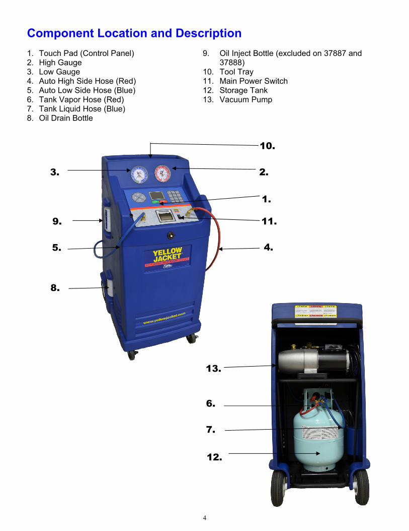
Component Location and Description 1. Touch Pad (Control Panel) 2. High Gauge 3. Low Gauge 4. Auto High Side Hose (Red) 5. Auto Low Side Hose (Blue) 6. Tank Vapor Hose (Red) 7. Tank Liquid Hose (Blue) 8. Oil Drain Bottle
9. Oil Inject Bottle (excluded on 37887 and 37888)
10. Tool Tray 11. Main Power Switch 12. Storage Tank 13. Vacuum Pump
11.
4.
1.
2.
8.
5.
9.
3.
10.
7.
6.
13.
14.
12.
5
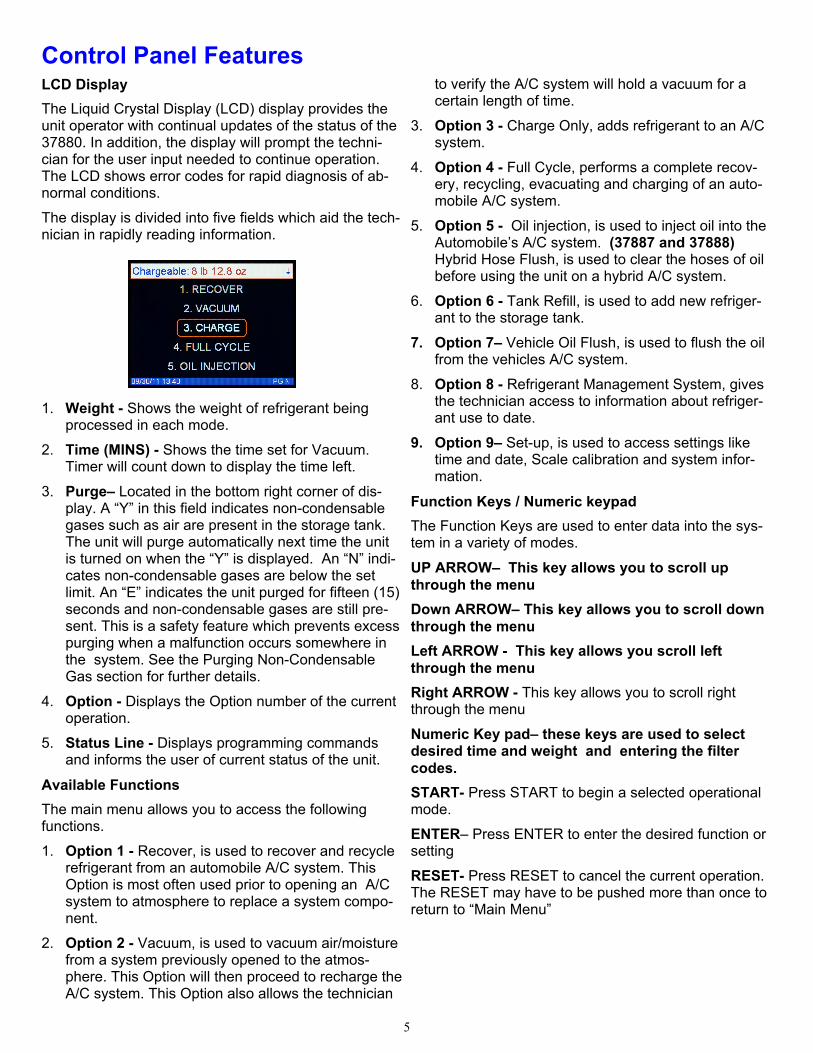
LCD Display
The Liquid Crystal Display (LCD) display provides the unit operator with continual updates of the status of the 37880. In addition, the display will prompt the techni-cian for the user input needed to continue operation. The LCD shows error codes for rapid diagnosis of ab-normal conditions.
The display is divided into five fields which aid the tech-nician in rapidly reading information.
1. Weight - Shows the weight of refrigerant being processed in each mode.
2. Time (MINS) - Shows the time set for Vacuum. Timer will count down to display the time left.
3. Purge– Located in the bottom right corner of dis-play. A “Y” in this field indicates non-condensable gases such as air are present in the storage tank. The unit will purge automatically next time the unit is turned on when the “Y” is displayed. An “N” indi-cates non-condensable gases are below the set limit. An “E” indicates the unit purged for fifteen (15) seconds and non-condensable gases are still pre-sent. This is a safety feature which prevents excess purging when a malfunction occurs somewhere in the system. See the Purging Non-Condensable Gas section for further details.
4. Option - Displays the Option number of the current operation.
5. Status Line - Displays programming commands and informs the user of current status of the unit.
Available Functions
The main menu allows you to access the following functions.
1. Option 1 - Recover, is used to recover and recycle refrigerant from an automobile A/C system. This Option is most often used prior to opening an A/C system to atmosphere to replace a system compo-nent.
2. Option 2 - Vacuum, is used to vacuum air/moisture from a system previously opened to the atmos-phere. This Option will then proceed to recharge the A/C system. This Option also allows the technician
to verify the A/C system will hold a vacuum for a certain length of time.
3. Option 3 - Charge Only, adds refrigerant to an A/C system.
4. Option 4 - Full Cycle, performs a complete recov-ery, recycling, evacuating and charging of an auto-mobile A/C system.
5. Option 5 - Oil injection, is used to inject oil into the Automobile’s A/C system. (37887 and 37888)Hybrid Hose Flush, is used to clear the hoses of oil before using the unit on a hybrid A/C system.
6. Option 6 - Tank Refill, is used to add new refriger-ant to the storage tank.
7. Option 7– Vehicle Oil Flush, is used to flush the oil from the vehicles A/C system.
8. Option 8 - Refrigerant Management System, gives the technician access to information about refriger-ant use to date.
9. Option 9– Set-up, is used to access settings like time and date, Scale calibration and system infor-mation.
Function Keys / Numeric keypad
The Function Keys are used to enter data into the sys-tem in a variety of modes.
UP ARROW– This key allows you to scroll up through the menu
Down ARROW– This key allows you to scroll down through the menu
Left ARROW - This key allows you scroll left through the menu
Right ARROW - This key allows you to scroll right through the menu
Numeric Key pad– these keys are used to select desired time and weight and entering the filter codes.
START- Press START to begin a selected operational mode.
ENTER– Press ENTER to enter the desired function or setting
RESET- Press RESET to cancel the current operation. The RESET may have to be pushed more than once to return to “Main Menu”
Control Panel Features
6
Initial Setup To ensure quick, successful integration of the 37880 into your shop, please follow these set-up procedures before the first use of the unit. Step 1: FILL VACUUM PUMP WITH OIL 1. Remove thumbscrews located under the vacuum
pump shelf. 2. Rotate the front of the vacuum pump out to expose
the oil fill port. 3. Remove the fill cap located on top of the vacuum
pump. 4. Using a funnel, insert oil to the oil level line using
the provided YELLOW JACKET vacuum pump oil. 5. Replace the oil fill cap. 6. Rotate the vacuum pump back into its original
position and replace the thumbscrews. Step 2: FILL SOURCE TANK WITH REFRIGERANT
(also see page 11) 1. Disconnect blue tank hose from tank.
2. Open blue tank valve and allow nitrogen in tank to vent.
3. Reconnect blue tank hose. 4. Attach the tank refill adapter (Part No. 19153) to the
R-134a virgin cylinder. WARNING: DO NOT OVER-TIGHTEN THE TANK REFILL ADAPTER.
5. Plug unit into a grounded 110V outlet. 6. Turn on the main power switch. 7. Select TANK REFIL from the main menu 8. Follow the user prompts to complete the tank refill
process. 9. When the display reads “SUPPLY TANK EMPTY”
disconnect blue hose. 10. Remove the tank refill adapter from empty R-134a
virgin cylinder and place it in the tool tray located on top of the unit.
The unit is now ready for operation. View training video at www.yellowjacket.com/trainingvideos.asp.
The Recovery Option should be used to fully recovery and recycle all refrigerant from an air conditioning system. For instance, if the system needs to be opened to atmosphere to replace a part, all refrigerant must be removed before opening the system.
RECOVER Operational Steps
1. Verify the automobile air conditioning system is off.
2. Select RECOVER for recovery operations. The LCD should read “CONNECT SERVICE HOSES TO VEHICLE ENTER TO CONTINUE.”
NOTE: If desired, the gauges of the 37880 SERIES can now be used to aid investigation of an A/C system problem. Ensure the automobile A/C system is turned off prior to selecting a mode on the machine.
3. Connect the high and low side auto service hoses to the respective high and low side service ports on the automobile A/C system. Open the service hose valves.
4. Press START to begin recovery operations.
WARNING: DO NOT RECOVER CONTAMINATED REFRIGERANT WITH THIS UNIT. RECOVERING CONTAMINATED REFRIGERANT WILL VOID ALL WARRANTIES AND MAY CAUSE DAMAGE TO OTHER AUTOMOBILES SERVICED IN THE FUTURE.
During the recovery operation, refrigerant is removed from both the high and low side of the automobile air condition-ing system. The LCD will display the amount of refrigerant
being recovered and the status line will read “RECOVERING REFRIGERANT.”
Note: If “RECOVERY HOLD” Option is selected The unit will stop at 6” of mercury and hold for five min as re-quired by EPA Per SAE J2211. If the pressure rises to 0 psi the compressor will restart and the unit will pull down to the required 6” of mercury and hold for two minutes. The unit will repeat this process until the system pressure remains stable at vacuum for two minutes or until it fails this process five times. If the process fails five times the status line will read “LEAK CHECK FAILED.” This may mean that the automobile A/C system has a gross leak and it will not hold a vacuum.
If this occurs take the appropriate steps to locate the leak and properly repair it.
If the “RECOVERY HOLD” option is not selected the unit will shut off at the required level of vacuum and the opera-tor must insure that the EPA standard (SAE J2211) is met.
After the system turns off, the unit will beep to alert the technician the job is complete. The oil removed from the auto will drain into the oil drain bottle on the side of the unit. Because a small amount of gas will be released as the oil drains, a small hissing sound may come from the bottle.
Always inspect hoses, o-rings, and fittings for damage be-fore using equipment. Replace worn or damaged compo-nents. Failure to insure that hoses, o-rings and fittings are in working order can increase a build-up of NCG’s in the recovered refrigerant.
RECOVER
7
Use only new lubricant to replace the amount removed during the recycling process. Discard used lubricant per applicable federal, state and local requirements.
5. Verify the message on the LCD reads “RECOVERY COMPLETE.”
6. Press the RESET key. The LCD should read “CHECK OIL LEVELS.”
7. Measure the oil in the oil drain bottle. Dispose of recovered oil in a proper manner.
8. Close the service valves and disconnect the high and low side auto service hoses from the automobile.
Models with the optional refrigerant identifier 37881/37888
The unit will display “IDENTIFY REFRIGERANT ?” To make your selection use the left or right arrow keys to toggle from YES to NO. Press the ENTER key to make your selection and then press the Start key to start the process. If YES is selected the unit will begin the refrig-erant identification process.
If the refrigerant does not pass the identification proc-ess (98% purity) the unit will display the error message “ CONTAMINATED” and the screen will show the results of the identification. Press the Reset key and follow the instructions on the screen and the unit will clear itself automatically. Repeat the identification proc-ess to insure the proper identification of the refrigerant purity level.
If the unit fails the second time follow the on screen in-structions and take the appropriate steps to remove the contaminated refrigerant with a separate unit for removal of contaminated refrigerant.
WARNING: DO NOT RECOVER CONTAMINATED REFRIGERANT WITH THIS UNIT. RECOVERING CONTAMINATED REFRIGERANT WILL VOID ALL WARRANTIES AND MY CAUSE DAMAGE TO OTHER AUTOMOBILES THAT YOU SERVICE IN THE FUTURE.
RECOVER, cont.
VACUUM The vacuum function of the 37880 SERIES is designed to remove air/moisture from the automobile A/C system by pulling a deep vacuum. This mode is most often used after completing a repair that required opening the A/C system to the atmosphere. Moisture in an A/C system can cause erratic operation and must be re-moved before recharging the system with refrigerant.
VACUUM Operational Steps
NOTE: If desired, the gauges of the 880 SERIES can now be used to aid investigation of an A/C sys-tem problem. Ensure the automobile A/C system is turned off prior to selecting a mode on the ma-chine.
1. Verify the auto air conditioning system is off.
2. Select Vacuum option from the main menu.
3. Press the ENTER key.
4. When the LCD reads “SET VACUUM TIME,” set the vacuum time by using the numeric keypad until the desired time is shown. press ENTER to accept the vacuum time shown on the LCD. Bypass vac-
uum time by setting time to zero (FULL CYCLE MODE only). Note: We recommend 10-15 mini-mum vacuum time to ensure proper charging.
5. When the LCD reads “SET VACUUM HOLD TIME,” set the vacuum hold time by using the nu-meric keypad until the desired time is shown. press ENTER to accept the vacuum hold time shown on the LCD. Vacuum hold time can be by-passed if the time is set to zero.
6. The display will now read “INJECT OIL AFTER VACUUM” YES or NO Press the left or right arrows to select YES or NO.
7. The LCD will read “CONNECT HOSES PRESS ENTER TO CONTINUE”
8. Connect the high and low side auto service hoses to the respective high and low side service ports on the automobile A/C system. Open the service hose valves.
9. Press the START key to begin the vacuum opera-tion.
8
VACUUM cont. Note: If the automobile A/C system has pressure on it, the unit will automatically begin a recovery cycle to in-sure that no refrigerant is released into the atmosphere.
10. The 37880 SERIES will begin to evacuate the A/C system and will beep to indicate the end of the vac-uum time.
11. Record the vacuum level shown on the LCD and press START to begin the vacuum hold time. The hold time will count down on the LCD and the unit will beep at the end of the hold time.
12. Record the final vacuum level shown on the LCD If the two recorded vacuum levels are different, the A/C system may have a leak and might not retain refrigerant when charged.
13. The unit will prompt you to “INJECT OIL NOW” press and hold the START key until the desired amount of oil is injected into the A/C system.
14. Verify the message on the LCD reads “VACUUM COMPLETE.”
15. Press the RESET key to return to the main menu.
16. Shut the service valves and disconnect the high and low side auto service hoses from the automobile.
Model 37889 with integrated micron gauge (Only) - See page 9 for instructions that will outline how to use this feature.
CHARGE The Charge Only function is designed to add a precise amount of refrigerant when the A/C system is low on refrigerant. This mode is most often used when the A/C system is working but does not produce sufficiently cold air. Note: THE A/C SYSTEM MUST BE IN A VACUUM BEFORE THE CHARGING PROCESS.
MODE 3 Operational Steps:
NOTE: If desired, the gauges of the 37880 can now be used to aid investigation of an A/C system prob-lem. Ensure the automobile A/C system is turned off prior to selecting a mode on the 37880.
1. Verify the auto air conditioning system is off.
2. Select CHARGE option from the main menu.
3. When the LCD reads “SET CHARGE AMOUNT,” set the amount of refrigerant to be charged into the A/C system by using the numeric keypad until the desired amount is shown. press ENTER to set the charge amount on the LCD. NOTE: To change units from pounds and ounces, ounces or kilograms press the START key. The unit will then ask you to confirm the charge amount. Press the ENTER key to confirm.
4. The LCD will read “CONNECT SERVICE HOSES TO THE VEHICLE ENTER TO CONTINUE”. Press the ENTER key.
5. Connect the high and low side auto service hoses to the respective high and low side service ports on the automobile A/C system. Open the service hose valves.
6. The LCD should read “PUSH START.”
7. Press START key to begin charging operations. The display will read “STABILIZING PLEASE WAIT” The 37880 Series will then start the charge cycle.
The LCD will display the charging process progress. The unit will beep when the desired charge amount has been transferred to the A/C system.
Note: The last 3 oz. of refrigerant charge will be me-tered in by the charging solenoid. It is normal to hear a clicking sound while charging.
8. Verify the message on the LCD reads “CHARGE COMPLETE.” Press the RESET key and the Unit will force a hose clearing routine. Close the service valves and disconnect the high and low side auto service hoses from the auto.
9. Press the ENTER key to return to the main menu
Low Side Charge
The system default setting is high-side charging. To charge low-side, follow these steps:
1. Turn the unit off.
2. Press and hold number 3 key down on the nu-meric key keypad and turn the unit on.
3. When the display reads “low side charge,” release the charge key.
4. Enter the charge amount.
Note: when the unit is turned off it will default back to high-side charge.
9
The Full Cycle function of the 37880 is designed to re-move and recycle all refrigerant in an A/C system by transferring the refrigerant to the storage tank, remove moisture in the system by pulling a vacuum, and charg-ing the system with a precise amount of refrigerant.
MODE 4 Operational Steps
NOTE: If desired, the gauges of the 37880 can now be used to aid investigation of an A/C system prob-lem. Ensure the automobile A/C system is turned off prior to selecting a mode on the 37880.
1. Verify the auto air conditioning system is off.
2. Select Full Cycle in the main menu. The LCD will read “SELECT VACUUM TIME”
3. When the LCD reads “SET VACUUM TIME,” set the vacuum time by entering the time using the nu-meric keypad until the desired time is shown. Press the ENTER key to continue.
4. When the LCD reads “SET VAC HOLD TIME,” set the vacuum hold time by entering the time using the numeric keypad until the desired time is shown. Press the ENTER key to continue.
Note: We recommend 10-15 minimum vacuum time to ensure proper charging.
NOTE: Vacuum hold time can be bypassed if the time is set to zero.
1. When the LCD reads “SET CHARGE AMOUNT,” set the charge amount by entering the amount us-ing the numeric keypad until the desired time is shown. Press the ENTER key to continue.
6. When the LCD reads “INJECT OIL AFTER VAC-UUM”, use the left and right arrow keys to toggle between YES and NO. Select YES or NO and press the ENTER key to continue.
7. The LCD should read ‘CONNECT SERVICE HOSES TO VEHICLE’,
8. Press START KEY to begin full cycle operations.
9. The unit will begin to recover as outlined for the Re-covery Only cycle, and then evacuate the A/C sys-tem and will beep to indicate the end of the vac-uum time— if Vacuum Hold is used.
10. Record the vacuum level shown on the low pres-sure gauge and press START to begin the vacuum hold time. The hold time will count down on the LCD and the unit will beep at the end of the hold time. If vacuum hold time was set to zero, the unit will transition into charge mode.
11. Record the final vacuum level shown on the low pressure gauge. If the two recorded levels are dif-ferent, the A/C system may have a leak and may not retain refrigerant when charged. The 37880 will automatically start the charge cycle.
12. The unit will prompt you to “INJECT OIL NOW” press and hold the START key until the desired amount of oil is injected into the A/C system.
13. The LCD will display the progress of the charging process. When the desired charge amount has been transferred to the A/C system, the unit will beep.
14. Verify the message on the LCD reads “FULL CYCLE COMPLETE.”
15. Press the RESET key. The LCD should read “CHECK OIL LEVELS.” The LCD will read “HOSES NEED CLEARING”
16. Press the Enter Key. The unit will then prompt you to “DISCONNECT VEHICLE.”
17. Shut the service valves and disconnect the high and low side auto service hoses from the auto.
18. Press the ENTER key; the LCD will read “CLEARING HOSES.”
19. Measure the oil in the oil drain bottle. Dispose of recovered oil in a proper manner.
20. Press the RESET key to return to the “SELECT MODE” status.
Model 37889 (Only) - The 37889 model has an inte-grated micron gauge that can be used to determine the micron level of the A/C System. The instructions below will outline how to use this feature. INTERGRATED MICRON GUAGE (37889 MODEL ONLY) The 37889 model has an integrated micron gauge that can be used to determine the micron level of the A/C system. The instructions below will outline how to use this feature . Full Cycle / Vacuum operations– Select micron level by using the up or down arrows. If you would rather enter a time for the vacuum cycle press the START key. Use the numeric keypad to set vacuum time. NOTE: Be-cause of the location of the vacuum sensor it may be necessary to set the micron lever lower to compensate Note: Since the micron sensor is inside the unit and not attached to the vehicle there will be a difference in the actual micron reading in the vehicle. To achieve the best results set the micron number lower than the micron level you want to reach.
FULL CYCLE
10
Models with the optional refrigerant identifier 37881/37888 The unit will display “IDENTIFY REFRIGERANT?” To make your selection use the left or right arrow keys to toggle from YES to NO. Press the ENTER key to make your selection and then press the START key to start the process. If YES is selected the unit will begin the refrigerant identification process. If the refrigerant does not pass the identification process (98% purity) the unit will display the error message “CONTAMINATED” and the screen will show the results of the identification. Press the RESET key and follow the instructions on the screen and the unit
will clear itself automatically. Repeat the identification process to insure the proper identification of the refrig-erant purity level. If the unit fails the second time follow the on screen in-structions and take the appropriate steps to remove the contaminated refrigerant with a separate unit for re-moval of contaminated refrigerant. WARNING: DO NOT RECOVER CONTAMINATED REFRIGERANT WITH THIS UNIT. RECOVERING CONTAMINATED REFRIGERANT WILL VOID ALL WARRANTIES AND MY CAUSE DAMAGE TO OTHER AUTOMOBILES THAT YOU SERVICE IN THE FUTURE.
FULL CYCLE cont.
HYBRID HOSE FLUSH The Hybrid Hose Flush feature is used to remove resid-ual oil and contaminates from the unit and hoses. The SAE J2788 H standard requires that the unit remove the residual oil so there isn't a risk of cross contaminat-ing the oil in a hybrid A/C system. Failure to perform
this function before working on a hybrid A/C system can cause serious issues with the electrical system. Having too much of the wrong type of oil in a hybrid A/C system can conduct the electricity to the outside of the A/C compressor.
SERVICING HIGH VOLTAGE A/C SYSTEMS (MODELS 37887 AND 37888 ONLY) Due to issues with oil contamination in High Voltage A/C systems the 37887 and the 37888 have a unique flushing feature that reduces cross contamination of oil below SAE and OEM specifications. It is necessary to perform the following procedure be-fore working on a High Voltage A/C system. 1. Select HYBRID HOSE FLUSH in the main menu 2. When the display reads “PLEASE CONNECT
FLUSH ADAPTER” connect the supplied flush adapter between the high and low side hoses.
3. Press the ENTER key to begin the process 4. The display will then read “FLUSHING HOSES
PLEASE WAIT” 5. When the process is complete press the RESET
key to return to the main menu.
WARNING
FAILURE TO PERFORM THIS PROCESS CAN CAUSE DAMAGE TO THE A/C SYSTEM COMPRES-SOR AS WELL AS OTHER ELECTRICAL COMPO-NENTS RELATED TO THE A/C SYSTEM. THE POSI-BILITY OF ELECTRICAL SHOCK TO THE TECHNI-CIAN OR OTHERS MAY ALSO OCCUR BY NOT PERFORMING THIS PROCESS
INTERGRATED MICRON GUAGE (37889 MODEL ONLY) The 37889 model has an integrated micron gauge that can be used to determine the micron level of the A/C system. The instructions below will outline how to use this feature .
Full Cycle / Vacuum operations– Select micron level by using the up or down arrows. If you would rather enter a time for the vacuum cycle press the START key. Use the numeric keypad to set vacuum time. NOTE: Be-cause of the location of the vacuum sensor it may be necessary to set the micron lever lower to compensate.
11
TANK REFILL In order to use the charging mode, you must have at least six (10) pounds of refrigerant in the storage tank. Follow this procedure to add refrigerant to the storage tank. When adding R-134a to the onboard storage tank you will need to use the tank refill adapter (PART NUM-BER 19153) supplied in the accessory kit. This adapter connects the low side auto service coupler to the tank of new R-134a refrigerant. It should be stored in the tool tray on the top of the unit.
1. Select TANK REFIL from the main menu.
2. Connect the blue low side auto service hose to the new refrigerant source tank and open the tank valve. Turn the source tank upside down to ensure all of the refrigerant is transferred to the storage tank on the unit. Press the ENTER key.
3. Make sure you are reading pressure on the low-side gauge.
4. Press the START key. Refrigerant will transfer to the storage tank. The unit will shut off automatically when either the supply tank is empty or the storage tank is full.
Press the RESET key to return to the main menu.
Models with the optional refrigerant identifier 37881/37888 The unit will display “IDENTIFY REFRIGERANT ?” To make your selection use left or right arrow keys to tog-gle from YES to NO. Press the ENTER key to make your selection and then press the START key to start the process. If yes is selected the unit will begin the re-frigerant identification process. If the refrigerant does not pass the identification proc-ess (98% purity) the unit will display the error message “ CONTAMINATED” and the screen will show the re-sults of the identification. Press the Reset key and fol-low the instructions on the screen and the unit will clear itself automatically. Repeat the identification process to insure the proper identification of the refrigerant purity level. If the unit fails the second time follow the on screen instructions and take the appropriate steps to remove the contaminated refrigerant with a separate unit for removal of contaminated refrigerant.
REFRIGERATION MANAGEMENT The Refrigerant Management System built into the 37880 tracks all aspects of refrigeration usage. The information can significantly help you manage your automobile A/C repair business. In addition, new fed-eral regulations require strict records of your refrigerant usage. The software in this system is designed to en-sure the highest possible accuracy in managing refrig-erant usage. Refrigerant measurement during charging is extremely accurate. In Charge mode, however, accu-racy is plus or minus 1/2 ounce based on variations in air temperature and pressure.
Uses of the refrigerant data include:
Improved record keeping
Accurate determination of net profits
Reduced billing errors
Minimized refrigerant loss from leaks and theft
Reduced operator errors
The refrigerant management information is stored in eight registers. To access the information, press Mode 7, REFRIGERANT MANAGEMENT SYSTEM. Press RMM key to cycle through the screens. The screens contain the following information:
Screen 1: Last Job Information Run Time Refrigerant Recovered Refrigerant Charged Refrigerant Added Screen 2: Year-to-date Information Total Run Time Total Amount Recovered Total Amount Charged Refrigerant Added “New”
WARNING
DO NOT RECOVER CONTAMINATED REFRIGERANT WITH THIS UNIT. RECOVERING CONTAMINATED REFRIGERANT WILL VOID ALL WARRANTIES AND MAY CAUSE DAMAGE TO OTHER AUTOMOBILES THAT YOU SERVICE IN THE FUTURE.
12
Purging Non-Condensable Gases The 37880 is designed to automatically purge non-condesable gases such as air present in the storage tank. When the pressure in the tank exceeds a treshold value, the unit will automatically purge the excess pressure. The unit will only purge when it is first turned on. The current purge status is displayed in the bottom right corner of the LCD when in Select Mode.
The purge status should be either “Y”, “N”, or “E.” A “Y” indicates air is present in the tank. The unit will purge the next time it is turned off and on. An “N” in the window indicates a purge is not needed.
An “E” will display on the LCD if the previous purge was insufficient to lower the non-condensable gas
value below the limit. The purge time is set to 15 seconds to minimize refrigerant loss. If the LCD continues to display an “E” after several purge cycles, there may be an error in the system. Check the pressure in the tank to determine if the system is purging unnecessarily.
contact Ritchie Engineering Customer Service at (800)769-8370.
The best time to check the purge function is after the unit has sat overnight and the tank temperature is stable.
Maintenance Reminders FILTER - MAINTENACE WARNING! CHANGE FIL-TER DRIER The 37880 has a unique filter system which ensures the refrigerant transferred to the storage cylinder is clean and moisture-free. The filters must be changed periodically to ensure the system is working properly. A maintenance reminder prompts you when to change your filters. All refrigerant must be removed from the old filters before they are removed. Follow the filter change procedures carefully to minimize refrigerant loss and ensure only clean, moisture-free refrigerant is transferred into the storage cylinder. The new J2788 standard requires that the unit lock out if the filter drier is not replaced at the proper interval. The unit will prompt you when it is near the end of its life. When the filter drier reaches 100 lbs of refrigerant processed it will warn the user that it is nearing the end of its life. When the filter drier reaches 150 lbs of refrig-erant processed it will lock the user out and require a filter change before the unit can be used again. The filter driers are marked with a unique code that will be required to unlock the unit.
Check Filter Life – Select the REF MANAGEMENT option in the main
menu.
Press the RIGHT ARROW key to view the remain-ing filter life.
Filter Change Procedure before Scheduled Filter Change. Follow these steps to change the filter drier before the scheduled filter change:
Hold down DOWN ARROW key and turn main power switch on.
When display reads “INPUT SERIAL NUMBER” enter serial number using the keypad.
Filter Change Procedure if Filter Lock Out is reached. When the display reads “ MAINTENACE WARN-
ING! CHANGE FILTER DRIER” Press Enter key to enter filter change mode. Enter serial number using the keypad
13
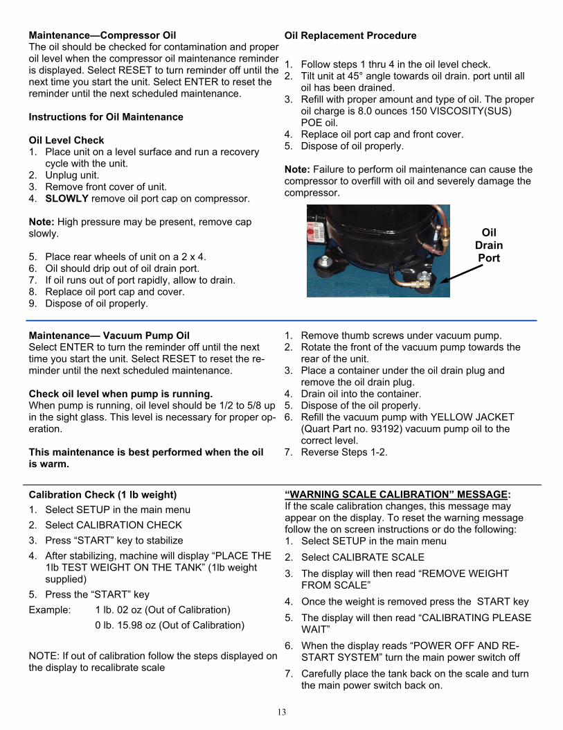
Maintenance—Compressor Oil The oil should be checked for contamination and proper oil level when the compressor oil maintenance reminder is displayed. Select RESET to turn reminder off until the next time you start the unit. Select ENTER to reset the reminder until the next scheduled maintenance. Instructions for Oil Maintenance Oil Level Check 1. Place unit on a level surface and run a recovery
cycle with the unit. 2. Unplug unit. 3. Remove front cover of unit. 4. SLOWLY remove oil port cap on compressor. Note: High pressure may be present, remove cap slowly. 5. Place rear wheels of unit on a 2 x 4. 6. Oil should drip out of oil drain port. 7. If oil runs out of port rapidly, allow to drain. 8. Replace oil port cap and cover. 9. Dispose of oil properly.
Oil Replacement Procedure
1. Follow steps 1 thru 4 in the oil level check. 2. Tilt unit at 45° angle towards oil drain. port until all
oil has been drained. 3. Refill with proper amount and type of oil. The proper
oil charge is 8.0 ounces 150 VISCOSITY(SUS) POE oil.
4. Replace oil port cap and front cover. 5. Dispose of oil properly. Note: Failure to perform oil maintenance can cause the compressor to overfill with oil and severely damage the compressor.
Oil Drain Port
Maintenance— Vacuum Pump Oil Select ENTER to turn the reminder off until the next time you start the unit. Select RESET to reset the re-minder until the next scheduled maintenance. Check oil level when pump is running. When pump is running, oil level should be 1/2 to 5/8 up in the sight glass. This level is necessary for proper op-eration. This maintenance is best performed when the oil is warm.
1. Remove thumb screws under vacuum pump. 2. Rotate the front of the vacuum pump towards the
rear of the unit. 3. Place a container under the oil drain plug and
remove the oil drain plug. 4. Drain oil into the container. 5. Dispose of the oil properly. 6. Refill the vacuum pump with YELLOW JACKET
(Quart Part no. 93192) vacuum pump oil to the correct level.
7. Reverse Steps 1-2.
Calibration Check (1 lb weight)
1. Select SETUP in the main menu
2. Select CALIBRATION CHECK
3. Press “START” key to stabilize
4. After stabilizing, machine will display “PLACE THE 1lb TEST WEIGHT ON THE TANK” (1lb weight supplied)
5. Press the “START” key
Example: 1 lb. 02 oz (Out of Calibration)
0 lb. 15.98 oz (Out of Calibration)
NOTE: If out of calibration follow the steps displayed on the display to recalibrate scale
“WARNING SCALE CALIBRATION” MESSAGE: If the scale calibration changes, this message may appear on the display. To reset the warning message follow the on screen instructions or do the following: 1. Select SETUP in the main menu
2. Select CALIBRATE SCALE
3. The display will then read “REMOVE WEIGHT FROM SCALE”
4. Once the weight is removed press the START key
5. The display will then read “CALIBRATING PLEASE WAIT”
6. When the display reads “POWER OFF AND RE-START SYSTEM” turn the main power switch off
7. Carefully place the tank back on the scale and turn the main power switch back on.
14
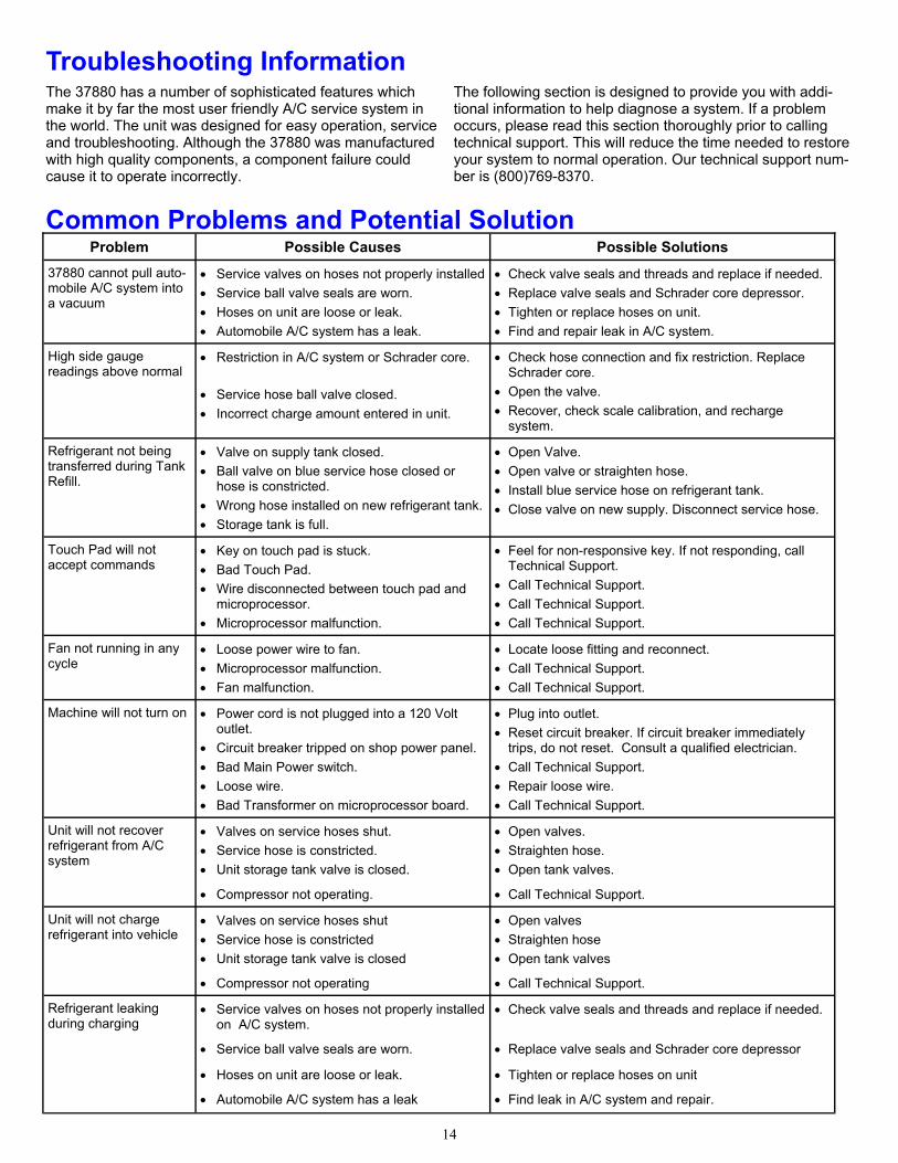
Common Problems and Potential Solution Problem Possible Causes Possible Solutions
37880 cannot pull auto-mobile A/C system into a vacuum
Service valves on hoses not properly installed
Service ball valve seals are worn.
Hoses on unit are loose or leak.
Automobile A/C system has a leak.
Check valve seals and threads and replace if needed.
Replace valve seals and Schrader core depressor.
Tighten or replace hoses on unit.
Find and repair leak in A/C system.
High side gauge readings above normal
Restriction in A/C system or Schrader core.
Service hose ball valve closed.
Incorrect charge amount entered in unit.
Check hose connection and fix restriction. Replace Schrader core.
Open the valve.
Recover, check scale calibration, and recharge system.
Refrigerant not being transferred during Tank Refill.
Valve on supply tank closed.
Ball valve on blue service hose closed or hose is constricted.
Wrong hose installed on new refrigerant tank.
Storage tank is full.
Open Valve.
Open valve or straighten hose.
Install blue service hose on refrigerant tank.
Close valve on new supply. Disconnect service hose.
Touch Pad will not accept commands
Key on touch pad is stuck.
Bad Touch Pad.
Wire disconnected between touch pad and microprocessor.
Microprocessor malfunction.
Feel for non-responsive key. If not responding, call Technical Support.
Call Technical Support.
Call Technical Support.
Call Technical Support.
Fan not running in any cycle
Loose power wire to fan.
Microprocessor malfunction.
Fan malfunction.
Locate loose fitting and reconnect.
Call Technical Support.
Call Technical Support.
Machine will not turn on Power cord is not plugged into a 120 Volt outlet.
Circuit breaker tripped on shop power panel.
Bad Main Power switch.
Loose wire.
Bad Transformer on microprocessor board.
Plug into outlet.
Reset circuit breaker. If circuit breaker immediately trips, do not reset. Consult a qualified electrician.
Call Technical Support.
Repair loose wire.
Call Technical Support.
Unit will not recover refrigerant from A/C system
Valves on service hoses shut.
Service hose is constricted.
Unit storage tank valve is closed.
Open valves.
Straighten hose.
Open tank valves.
Compressor not operating. Call Technical Support.
Unit will not charge refrigerant into vehicle
Valves on service hoses shut
Service hose is constricted
Unit storage tank valve is closed
Open valves
Straighten hose
Open tank valves
Compressor not operating Call Technical Support.
Refrigerant leaking during charging
Service valves on hoses not properly installed on A/C system.
Check valve seals and threads and replace if needed.
Service ball valve seals are worn. Replace valve seals and Schrader core depressor
Hoses on unit are loose or leak. Tighten or replace hoses on unit
Automobile A/C system has a leak Find leak in A/C system and repair.
Troubleshooting Information The 37880 has a number of sophisticated features which make it by far the most user friendly A/C service system in the world. The unit was designed for easy operation, service and troubleshooting. Although the 37880 was manufactured with high quality components, a component failure could cause it to operate incorrectly.
The following section is designed to provide you with addi-tional information to help diagnose a system. If a problem occurs, please read this section thoroughly prior to calling technical support. This will reduce the time needed to restore your system to normal operation. Our technical support num-ber is (800)769-8370.
15
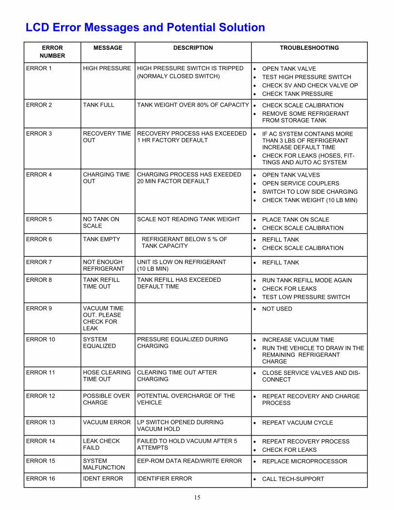
LCD Error Messages and Potential Solution ERROR
NUMBER MESSAGE DESCRIPTION TROUBLESHOOTING
ERROR 1 HIGH PRESSURE HIGH PRESSURE SWITCH IS TRIPPED (NORMALY CLOSED SWITCH)
OPEN TANK VALVE
TEST HIGH PRESSURE SWITCH
CHECK SV AND CHECK VALVE OP
CHECK TANK PRESSURE
ERROR 2 TANK FULL TANK WEIGHT OVER 80% OF CAPACITY CHECK SCALE CALIBRATION
REMOVE SOME REFRIGERANT FROM STORAGE TANK
ERROR 3 RECOVERY TIME OUT
RECOVERY PROCESS HAS EXCEEDED 1 HR FACTORY DEFAULT
IF AC SYSTEM CONTAINS MORE THAN 3 LBS OF REFRIGERANT INCREASE DEFAULT TIME
CHECK FOR LEAKS (HOSES, FIT-TINGS AND AUTO AC SYSTEM
ERROR 4 CHARGING TIME OUT
CHARGING PROCESS HAS EXEEDED 20 MIN FACTOR DEFAULT
OPEN TANK VALVES
OPEN SERVICE COUPLERS
SWITCH TO LOW SIDE CHARGING
CHECK TANK WEIGHT (10 LB MIN)
ERROR 5 NO TANK ON SCALE
SCALE NOT READING TANK WEIGHT PLACE TANK ON SCALE
CHECK SCALE CALIBRATION
ERROR 6 TANK EMPTY REFRIGERANT BELOW 5 % OF TANK CAPACITY
REFILL TANK
CHECK SCALE CALIBRATION
ERROR 7 NOT ENOUGH REFRIGERANT
UNIT IS LOW ON REFRIGERANT (10 LB MIN)
REFILL TANK
ERROR 8 TANK REFILL TIME OUT
TANK REFILL HAS EXCEEDED DEFAULT TIME
RUN TANK REFILL MODE AGAIN
CHECK FOR LEAKS
TEST LOW PRESSURE SWITCH
ERROR 9 VACUUM TIME OUT. PLEASE CHECK FOR LEAK
NOT USED
ERROR 10 SYSTEM EQUALIZED
PRESSURE EQUALIZED DURING CHARGING
INCREASE VACUUM TIME
RUN THE VEHICLE TO DRAW IN THE REMAINING REFRIGERANT CHARGE
ERROR 11 HOSE CLEARING TIME OUT
CLEARING TIME OUT AFTER CHARGING
CLOSE SERVICE VALVES AND DIS-CONNECT
ERROR 12 POSSIBLE OVER CHARGE
POTENTIAL OVERCHARGE OF THE VEHICLE
REPEAT RECOVERY AND CHARGE PROCESS
ERROR 13 VACUUM ERROR LP SWITCH OPENED DURRING VACUUM HOLD
REPEAT VACUUM CYCLE
ERROR 14 LEAK CHECK FAILD
FAILED TO HOLD VACUUM AFTER 5 ATTEMPTS
REPEAT RECOVERY PROCESS
CHECK FOR LEAKS
ERROR 15 SYSTEM MALFUNCTION
EEP-ROM DATA READ/WRITE ERROR REPLACE MICROPROCESSOR
ERROR 16 IDENT ERROR IDENTIFIER ERROR CALL TECH-SUPPORT
16
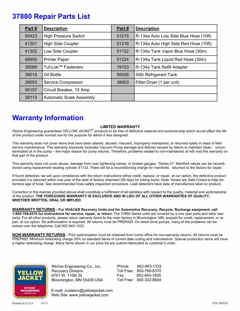
37880 Repair Parts List Part # Description
95423 High Pressure Switch
41301 High Side Coupler
41302 Low Side Coupler
68950 Printer Paper
38089 Tuf-Lok™ Fasteners
38019 Oil Bottle
38053 Service Compressor
95157 Circuit Breaker, 15 Amp
38113 Automatic Scale Assembly
Part # Description
01215 R-134a Auto Low Side Blue Hose (10ft)
01216 R-134a Auto High Side Red Hose (10ft)
01152 R-134a Tank Vapor Blue Hose (30in)
01224 R-134a Tank Liquid Red Hose (30in)
19153 R-134a Tank Refill Adapter
95006 50lb Refrigerant Tank
38003 Filter-Dryer (1 per unit)
Ritchie Engineering Co., Inc. Recovery Division 6701 W. 110th St. Bloomington, MN 55438 USA
Phone: 952-943-1333 Toll Free: 800-769-8370 Fax: 952-943-1605 Toll Free: 800-322-8684
E-mail: [email protected] Web Site: www.yellowjacket.com
Warranty Information LIMITED WARRANTY
Ritchie Engineering guarantees YELLOW JACKET® products to be free of defective material and workmanship which would affect the life of the product under normal use for the purpose for which it was designed. This warranty does not cover items that have been altered, abused, misused, improperly maintained, or returned solely in need of field service maintenance. This warranty expressly excludes Vacuum Pump damage and failures caused by failure to maintain clean, uncon-taminated oil in the pump – the major reason for pump returns. Therefore, problems related to non-maintained oil will void this warranty on that part of the product. This warranty does not cover abuse, damage from over tightening valves, or broken gauges. “Series 41” Manifold valves can be recondi-tioned using replacement seating cylinder 41133. There will be a reconditioning charge for manifolds returned to the factory for repair. If found defective, we will upon compliance with the return instructions either credit, replace, or repair, at our option, the defective product provided it is returned within one year of the date of factory shipment (90 days for tubing tools). Note: Hoses are Date Coded to help de-termine age of hose. See recommended hose safety inspection procedure. Leak detectors have date of manufacture label on product. Correction in the manner provided above shall constitute a fulfillment of all liabilities with respect to the quality, material and workmanship of the product. THE FOREGOING WARRANTY IS EXCLUSIVE AND IN LIEU OF ALL OTHER WARRANTIES OF QUALITY, WHETHER WRITTEN, ORAL OR IMPLIED.
WARRANTY RETURNS - For HVAC&R Recovery Units and for Automotive Recovery, Recycle, Recharge equipment, call 1-800-769-8370 for instructions for service, repair, or return. The 37880 Series units are covered by a one year parts and labor war-ranty. For all other products, please return warranty items to the main factory in Bloomington, MN, prepaid for credit, replacement, or re-pair, at our option. No authorization is required. All returns must be PREPAID. On direct drive pumps, many of the problems can be solved over the telephone. Call 952-943-1333. NON-WARRANTY RETURNS - Prior authorization must be obtained from home office for non-warranty returns. All returns must be PREPAID. Minimum restocking charge 20% on standard items of current date coding and manufacture. Special production items will have a higher restocking charge. Many items shown in our price list are custom-fabricated to customer’s order.
Printed in U.S.A 10/11 P/N 380539