R134a RECOVERY/RECYCLE/RECHARGE Operating … · R134a RECOVERY/RECYCLE/RECHARGE Operating...
24
R134a RECOVERY/RECYCLE/RECHARGE Operating Instructions WARNING!! Do not stop the recovery process. Permanent damage will occur that could void the warranty. COMMANDER1000 (-E) COMMANDER2000 (-E) COMMANDER3000 (-E)
Transcript of R134a RECOVERY/RECYCLE/RECHARGE Operating … · R134a RECOVERY/RECYCLE/RECHARGE Operating...
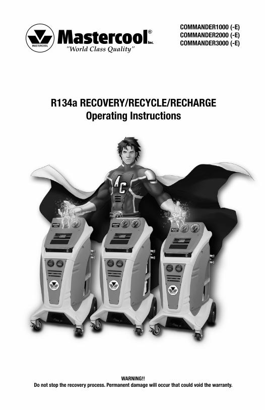
R134a RECOVERY/RECYCLE/RECHARGEOperating Instructions
WARNING!!Do not stop the recovery process. Permanent damage will occur that could void the warranty.
COMMANDER1000 (-E)COMMANDER2000 (-E)COMMANDER3000 (-E)

2 www.mastercool.com
3www.mastercool.com
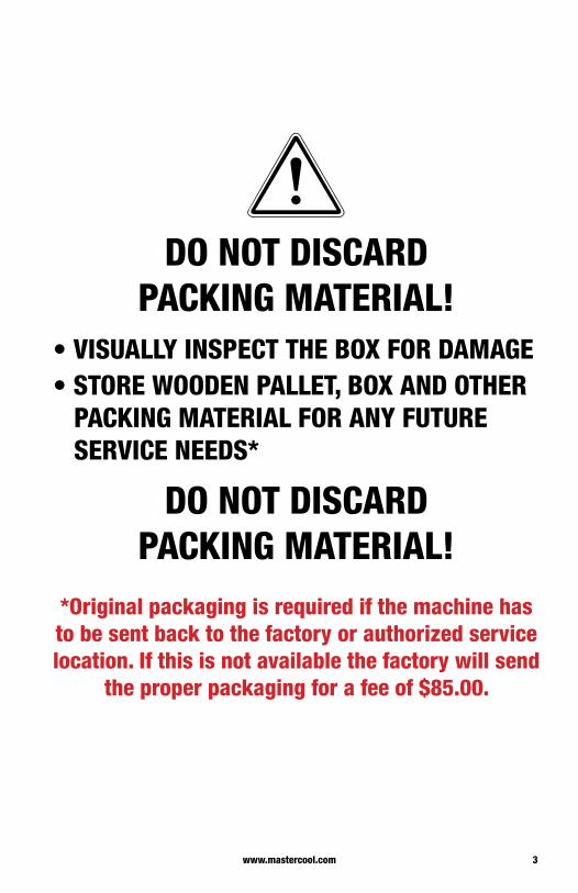
DO NOT DISCARD PACKING MATERIAL!
• VISUALLY INSPECT THE BOX FOR DAMAGE• STORE WOODEN PALLET, BOX AND OTHER PACKING MATERIAL FOR ANY FUTURE SERVICE NEEDS*
DO NOT DISCARD PACKING MATERIAL!
*Original packaging is required if the machine has to be sent back to the factory or authorized service location. If this is not available the factory will send
the proper packaging for a fee of $85.00.

4 www.mastercool.com
INTRODUCTIONThis machine is ETL Laboratories approved, in compliance with SAE J2788. We are dedicated to solving the issues surrounding the safe containment and proper management of refrigerants. Your new machine incorporates the latest technology and state of the art features to aid you in servicing R134a air conditioning and refrigeration systems.
NOTICE: The SAE J2788 standard has, by design made recycling machines more complex than previous models that some End Users might be familiar with. Some noticeable changes that the End User should expect from ALL new recycling machines are the following:
1. RECOVERY TIME: The average recovery time is approximately 30 minutes. This time is necessary to meet the SAE J2788 standard which requires that the machine recovers at least 95% of the AC system refrigerant and cleans the refrigerant to a minimum of 95% purity.
2. HOT WEATHER: As the ambient temperature approaches 100°F, some End Users have experienced an increase in recovery time. This is due to the natural response of R134a when its temperature is elevated. R134a has difficulty transforming from a gas into a liquid state at elevated temperatures. The transformation into liquid is necessary for the machine to complete the recovery process. The End User might notice the same effect when performing a TANK CHARGING operation. The COMMANDER series includes a color touch screen tablet that may experience a slower processing time in extreme heat and humidity. Avoid exposing the machine to dramatic changes in temperature or humidity.
3. COLD WEATHER: As the ambient temperature approaches 50°F, some End Users have experienced an increase in recovery time. This is due to the natural response of R134a when its temperature is lowered. R134a has difficulty transforming from a liquid into a vapor state at reduced temperatures. The transformation into vapor is necessary for the machine to complete the distilling process. The End User might notice the same effect when performing a TANK CHARGING operation. The COMMANDER series includes a color touch screen tablet that may experience a slower processing time in extreme cold and humidity. Avoid exposing the machine to dramatic changes in temperature or humidity.
4. SUN GLARE: Because of the way the COMMANDER color touch screen is constructed the user may experience mirror-like screen reflectivity or screen images that are too dim to read in direct sunlight. Whenever possible keep the color touch screen out of direct sunlight.
SAFETY SUMMARYThe following safety information is provided as guidelines to help you operate your new system under the safest possible conditions. Any equipment that uses chemicals can be potentially dangerous to use when safety or safe handling instructions are not known or not followed. The following safety instructions are to provide the user with the information necessary for safe use and operation. Please read and retain these instructions for the continued safe use of your service system.
SAFETY INFORMATIONEvery craftsman respects the tools with which they work. They know that the tools represent years of constantly improved designs and developments. The true craftsman also knows that tools are dangerous if misused or abused. To reduce risk of discomfort, illness, or even death, read, understand, and follow the following safety instructions. In addition, make certain that anyone else that uses this equipment understands and follows these safety instructions as well.
READ ALL SAFETY INFORMATION CAREFULLY before attempting to install, operate, or service this equipment. Failure to comply with these instructions could result in personal injury and/or property damage.
RETAIN THE FOLLOWING SAFETY INFORMATION FOR FUTURE REFERENCE.
Published standards on safety are available and are listed at the end of this section under ADDITIONAL SAFETY INFORMATION.
The National Electrical Code, Occupational Safety and Health Act regulations, local industrial codes and local inspection requirements also provide a basis for equipment installation, use, and service.
The following safety alert symbols identify important safety messages in this manual.
When you see one of the symbols shown here, be alert to the possibility of personal injury and carefully read the message that follows.
Never fill the tank to more than 80% of maximum capacity as this will not leave an expansion chamber for
5www.mastercool.com
absorbing any pressure increases.
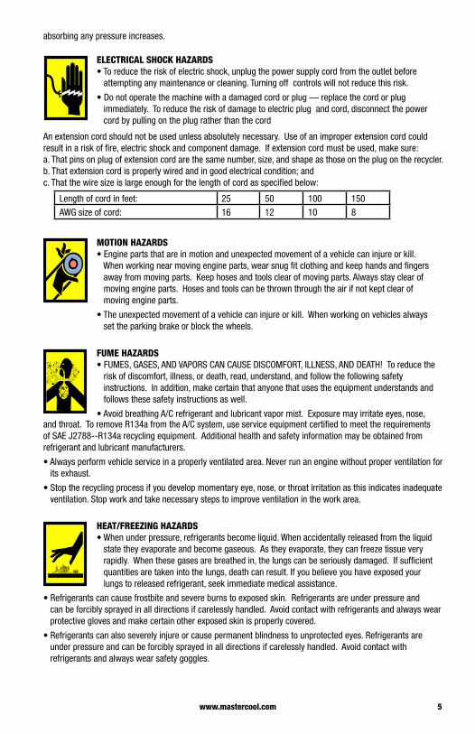
ELECTRICAL SHOCK HAZARDS• To reduce the risk of electric shock, unplug the power supply cord from the outlet before attempting any maintenance or cleaning. Turning off controls will not reduce this risk.
• Do not operate the machine with a damaged cord or plug — replace the cord or plug immediately. To reduce the risk of damage to electric plug and cord, disconnect the power cord by pulling on the plug rather than the cord
An extension cord should not be used unless absolutely necessary. Use of an improper extension cord could result in a risk of fire, electric shock and component damage. If extension cord must be used, make sure:a. That pins on plug of extension cord are the same number, size, and shape as those on the plug on the recycler.b. That extension cord is properly wired and in good electrical condition; andc. That the wire size is large enough for the length of cord as specified below:
Length of cord in feet: 25 50 100 150AWG size of cord: 16 12 10 8
MOTION HAZARDS• Engine parts that are in motion and unexpected movement of a vehicle can injure or kill. When working near moving engine parts, wear snug fit clothing and keep hands and fingers away from moving parts. Keep hoses and tools clear of moving parts. Always stay clear of moving engine parts. Hoses and tools can be thrown through the air if not kept clear of moving engine parts.
• The unexpected movement of a vehicle can injure or kill. When working on vehicles always set the parking brake or block the wheels.
FUME HAZARDS• FUMES, GASES, AND VAPORS CAN CAUSE DISCOMFORT, ILLNESS, AND DEATH! To reduce the risk of discomfort, illness, or death, read, understand, and follow the following safety instructions. In addition, make certain that anyone that uses the equipment understands and follows these safety instructions as well.
• Avoid breathing A/C refrigerant and lubricant vapor mist. Exposure may irritate eyes, nose, and throat. To remove R134a from the A/C system, use service equipment certified to meet the requirements of SAE J2788--R134a recycling equipment. Additional health and safety information may be obtained from refrigerant and lubricant manufacturers.
• Always perform vehicle service in a properly ventilated area. Never run an engine without proper ventilation for its exhaust.
• Stop the recycling process if you develop momentary eye, nose, or throat irritation as this indicates inadequate ventilation. Stop work and take necessary steps to improve ventilation in the work area.
HEAT/FREEZING HAZARDS• When under pressure, refrigerants become liquid. When accidentally released from the liquid state they evaporate and become gaseous. As they evaporate, they can freeze tissue very rapidly. When these gases are breathed in, the lungs can be seriously damaged. If sufficient quantities are taken into the lungs, death can result. If you believe you have exposed your lungs to released refrigerant, seek immediate medical assistance.
• Refrigerants can cause frostbite and severe burns to exposed skin. Refrigerants are under pressure and can be forcibly sprayed in all directions if carelessly handled. Avoid contact with refrigerants and always wear protective gloves and make certain other exposed skin is properly covered.
• Refrigerants can also severely injure or cause permanent blindness to unprotected eyes. Refrigerants are under pressure and can be forcibly sprayed in all directions if carelessly handled. Avoid contact with refrigerants and always wear safety goggles.
6 www.mastercool.com
EXPLOSION/FLAME HAZARDS• Never recover anything other than the approved refrigerants as specified on the machine. Alternate refrigerants may contain flammables such as butane or propane and can explode or cause a fire. Recovering alternate refrigerants will also void the warranty on your machine.
• For general safety reasons, at the end of the working day or in between services (when services do not immediately follow), see to it that all valves on hoses and the machine are closed.
ADDITIONAL SAFETY INFORMATIONFor additional information concerning safety, refer to the following standards.ANSI Standard Z87.1 — SAFE PRACTICE FOR OCCUPATION AND EDUCATIONAL EYE AND FACE PROTECTION - obtainable from the American National Standards Institute, 11 West 42nd St., New York, NY 10036, Telephone (212) 642-4900, Fax (212) 398-0023 - www.ansi.org
CAUTION: This equipment should be used in locations with mechanical ventilation that provides at least four air changes per hour or the equipment should be located at least 18 inches (457 mm) above the floor, or the equivalent.
CAUTION: Do not pressure test or leak test R134a service equipment and/or vehicle air conditioning systems with compressed air. Some mixtures of air and R134a have been shown to be combustible at elevated pressures. These mixtures, if ignited, may cause injury or property damage. Additional health and safety information may be obtained from refrigerant manufacturers.
ATTENTION: Technicians using this equipment must be certified under EPA Section 609 (Environmental Protection Agency).
WARNING: There is the possibility of refrigerant contamination in the refrigerant container or the mobile A/C system being serviced or refrigerant container. Before recycling use proper equipment such as a refrigerant identifier, if necessary.
NOTE: Use only new refrigerant oil to replace the amount removed during the recycling process. Used oil should be discarded per applicable federal, state, and local requirements.
The manufacturer shall not be responsible for any additional costs associated with a product failure including, but not limited to, loss of work time, loss of refrigerant, cross contamination of refrigerant, and unauthorized shipping and/or labor charges.
IMPORTANT: R134a systems have special fittings (per SAE specifications) to avoid cross-contamination with R12 systems. DO NOT adapt your unit for a different refrigerant — system failure will result.
PERIODICALLY INSPECT AND MAINTAIN REFRIGERANT HOSES AND SEALS TO ENSURE THAT HOSES AND SEALS PREVENT THE ADDITION OF EXCESS AIR, DUE TO LEAKS, DURING THE RECOVERY PROCESS, WHICH WOULD INCREASE THE NCG LEVEL IN THE RECOVERED REFRIGERANT.
CERTIFICATIONAll technicians opening the refrigeration circuit in automotive air conditioning systems must now be certified in refrigerant recovery and recycling procedures to be in compliance with Section 609 of the Clean Air Act Amendments of 1990. For information on certification call MACS Worldwide at (215) 631-7020.
ABOUT THIS MANUALThis manual includes a SAFETY SUMMARY, MACHINE PREPARATION FOR USE, OPERATION procedures, and MAINTENANCE instructions, for your Air Conditioning Service Center. Anyone intending to use the machine should become familiar with ALL the information included in this manual (especially the SAFETY SUMMARY) before attempting to use it.
Before operating this machine for the first time, perform all Setup instructions. If your new machine is not properly prepared to perform a service, your service data could be erroneous. In order to properly perform a complete air conditioning service, follow all procedures in the order presented. Please take the time to study this manual before operating the machine. Then keep this manual close at hand for future reference. Please pay close attention to the SAFETY SUMMARY and all WARNINGS and CAUTIONS provided throughout this manual.
ABOUT YOUR AIR CONDITIONING RECOVERY/RECYCLE SERVICE CENTERYour machine incorporates a highly accurate electronic scale for determining charging weights, etc. Other
7www.mastercool.com
functions can also be performed with the electronic scale as you will discover during the operating procedures. Either standard or metric units of measure can be selected. Your new machine has been designed specifically to use R134a, to operate within the objectives of the Montreal Protocol.
WARRANTYThis product is warranted against any defect in materials and/or construction for a period of 1 (one) year from the date of activation.
The machine is automatically activated upon initial startup. This activation will record the date and time your machine is turned on and establishes the warranty. Please reference the serial number and tag number in any warranty requests. This information can be found by pressing the >> on the middle, left side of the command center to access the main menu, then selecting help.
The warranty consists of free-of-charge replacement or repair of defective component parts or parts considered defective by the Manufacturer. Reference to the machine serial number must be included in any requests for spare parts. This warranty does not cover defects arising from normal wear, incorrect or improper installation, or phenomena not inherent to normal use and operation of the product.
NOTE: Regarding the above, the Manufacturer reminds the Customer that according to international and national laws and regulations in force the goods are shipped at the sole risk of the latter and, unless otherwise specified in the confirmation of order phase, the goods are shipped uninsured. The Manufacturer therefore declines any and all responsibility in merit of CLAIMS for damages due to shipping, loading and unloading, and unpacking.
The product for which repair under guarantee is requested must be shipped to the manufacturer under the customer’s exclusive responsibility and at the customer’s exclusive expense and risk. In order to avoid damage during shipping for repairs, the Manufacturer’s original packing must always be used.
The manufacturer declines any and all responsibility for damage to vehicles on which recovery/recycling and recharging are performed if said damage is the result of unskillful handling by the operator or of failure to observe the basic safety rules set forth in the instruction manual.
The warranty will expire automatically at the end of the 12 month period or whenever one of the following occurs: failure to perform maintenance; use of improper maintenance procedures; use of unsuitable lubricants and/or tracer fluids; inept or improper use; repairs performed by unauthorized personnel and/or with non-original spare parts; damage caused by shocks, fires, or other accidental events.
All warranty information referenced is valid in the United States only. For information pertaining the warranty outside of the United States, please contact your local distributor.
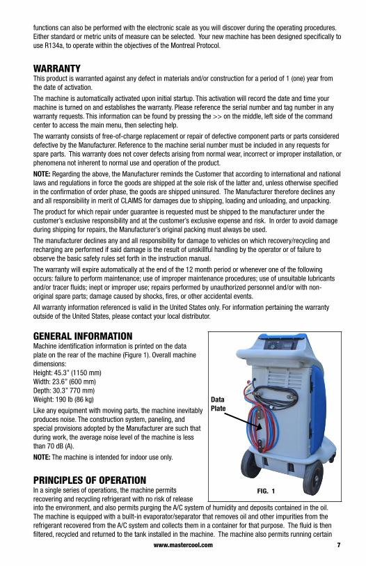
GENERAL INFORMATIONMachine identification information is printed on the data plate on the rear of the machine (Figure 1). Overall machine dimensions:Height: 45.3” (1150 mm)Width: 23.6” (600 mm)Depth: 30.3” 770 mm)Weight: 190 lb (86 kg)
Like any equipment with moving parts, the machine inevitably produces noise. The construction system, paneling, and special provisions adopted by the Manufacturer are such that during work, the average noise level of the machine is less than 70 dB (A).
NOTE: The machine is intended for indoor use only.
PRINCIPLES OF OPERATIONIn a single series of operations, the machine permits recovering and recycling refrigerant with no risk of release
Data Plate
FIG. 1
into the environment, and also permits purging the A/C system of humidity and deposits contained in the oil. The machine is equipped with a built-in evaporator/separator that removes oil and other impurities from the refrigerant recovered from the A/C system and collects them in a container for that purpose. The fluid is then filtered, recycled and returned to the tank installed in the machine. The machine also permits running certain
8 www.mastercool.com
operational and leak tests on the A/C system.
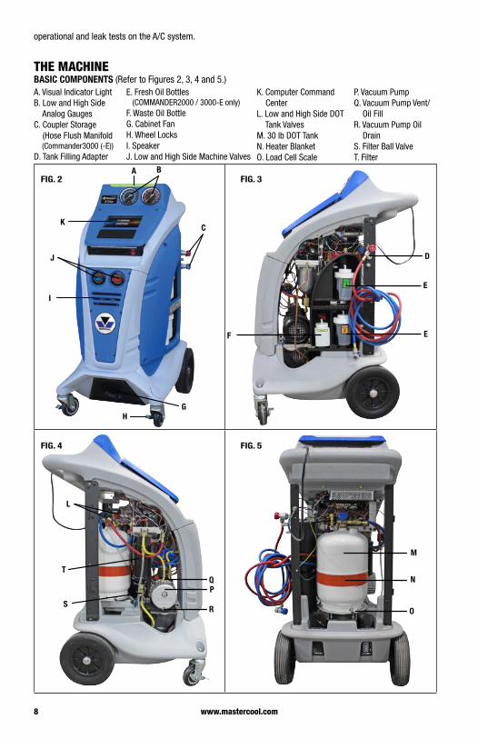
THE MACHINEBASIC COMPONENTS (Refer to Figures 2, 3, 4 and 5.)A. Visual Indicator Light B. Low and High Side Analog Gauges C. Coupler Storage (Hose Flush Manifold (Commander3000 (-E)) D. Tank Filling Adapter
E. Fresh Oil Bottles (COMMANDER2000 / 3000-E only) F. Waste Oil Bottle G. Cabinet Fan H. Wheel Locks I. Speaker J. Low and High Side Machine Valves
K. Computer Command Center L. Low and High Side DOT Tank Valves M. 30 lb DOT Tank N. Heater Blanket O. Load Cell Scale
P. Vacuum Pump Q. Vacuum Pump Vent/ Oil Fill R. Vacuum Pump Oil Drain S. Filter Ball Valve T. Filter
C
A B
GH
I
J
K
D
E
F E
L
PQ
RS
T
M
N
O
FIG. 2 FIG. 3
FIG. 4 FIG. 5
9www.mastercool.com
The COMMANDER3000 (-E) has the capabilities to perform reclamations on all standard and hybrid R134a vehicles. The COMMANDER2000 (-E)/COMMANDER1000 (-E) has the capabilities to perform reclamations on standard R134a vehicles only.
To begin using the COMMANDER machine, turn the power switch to the “ON” position. The power switch is located on the front right of the machine. Allow a few seconds for the computer command center to power up.
Upon initial startup the language screen will appear. Choose from one of the 18 languages programmed into the machine. Press the circle next to the language desired and press next. The command center will then display a series of welcome screens that will provide useful information to first time users.
When the COMMANDER machine powers up, the command center, will display the automatic/manual screen for COMMANDER3000 (-E) and COMMANDER2000 (-E). The COMMANDER1000 (-E) will display only the manual screen.
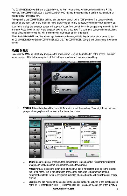
MAIN MENU To access the MAIN MENU at any time press the small arrows (<<) on the middle left of the screen. The main menu consists of the following options: status, settings, maintenance, documents and help.
• STATUS: This will display all the current information about the machine. Tank, oil, info and vacuum pump runtime graphics will be seen at the top of the screen.
o TANK: Displays internal pressure, tank temperature, total amount of refrigerant (refrigerant weight) and total amount of refrigerant available for charging
NOTE: Per SAE regulations a minimum of 2 kg (4.4 lbs) of refrigerant must be in the internal tank at all times. This is the difference between the displayed refrigerant weight and refrigerant available. Refer to refrigerant available when setting the vehicle refrigerant charge amount.
o OIL: Displays the volume of the used oil in the used oil bottle, the volume of the injection oil in bottle #1 (COMMANDER2000 (-E), COMMANDER3000-E only) and the volume of the injection
10 www.mastercool.com
oil in bottle #2 (COMMANDER2000 (-E), COMMANDER3000-E only)
o INFO: Displays vehicle A/C pressure (when the hoses and couplers are connected to the vehicle, valves on the machine are open and couplers are turned completely clockwise), distiller pressure (pressure/vacuum reading for the distiller), board temperature (the temperature of the circuit board) and filter life (percentage of remaining filter life.)
NOTE: Check periodically for the remaining filter life. Purchase a replacement filter before 100% is reached, or you will not be able to use the machine.
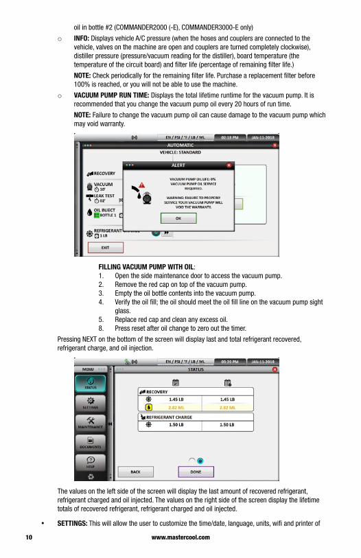
o VACUUM PUMP RUN TIME: Displays the total lifetime runtime for the vacuum pump. It is recommended that you change the vacuum pump oil every 20 hours of run time.
NOTE: Failure to change the vacuum pump oil can cause damage to the vacuum pump which may void warranty.
FILLING VACUUM PUMP WITH OIL:1. Open the side maintenance door to access the vacuum pump. 2. Remove the red cap on top of the vacuum pump. 3. Empty the oil bottle contents into the vacuum pump.4. Verify the oil fill; the oil should meet the oil fill line on the vacuum pump sight
glass. 5. Replace red cap and clean any excess oil.8. Press reset after oil change to zero out the timer.
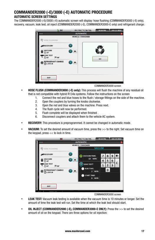
Pressing NEXT on the bottom of the screen will display last and total refrigerant recovered, refrigerant charge, and oil injection.
The values on the left side of the screen will display the last amount of recovered refrigerant, refrigerant charged and oil injected. The values on the right side of the screen display the lifetime totals of recovered refrigerant, refrigerant charged and oil injected.
• SETTINGS: This will allow the user to customize the time/date, language, units, wifi and printer of

11www.mastercool.com
the COMMANDER machine.
o TIME/DATE: To set the time and date press the corresponding up or down arrows. Press update to lock in the selection.
o LANGUAGE: Choose from one of the 18 languages programmed into the machine. Press the circle next to the language desired. Select update to lock in the selection.
o UNITS: From the units screen select the desired pressure and weights that will be displayed on the machine. Pressure can be selected in PSI or BAR, Temperature in Fahrenheit or Celsius, Volume in fluid ounces (FL. OZ) or milliliters (ML), and Weight in pounds (LB), ounces (OZ), pounds and ounces (LB:OZ), grams (GR) or kilograms (KG). Select update to lock in the selection.

12 www.mastercool.com
o WIFI: Enter the wifi password to establish an internet connection for real time, interactive communication, troubleshooting and software updates.
o PRINTER (COMMANDER3000 (-E) only): Type in the desired header on the keyboard that will be on the top of the printout. Press the test button for a sample printout. Press update to lock in the selection.
• MAINTENANCE: This will display the required routine maintenance (tank filling, purge, filter change, utilities, self test, hose flushing and identification) that needs to be performed

13www.mastercool.com
o TANK FILLING: Internal tank filling is preset to 15 pounds for optimal machine performance. This operation will be performed in the initial set up of the machine and whenever additional refrigerant is required. Refer to tank filling in the set up instructions.
o PURGE: The purge feature allows the machine to manually purge NCG (air) from the internal storage tank. The operator can manually start the purge process and the machine will automatically stop when purge is complete. The machine also routinely performs this operation, automatically during the recovery process.
o FILTER CHANGE: The percentage of filter life can be viewed in the status screen. To change the internal filter, follow the instructions on the screen.
CAUTION: Please wear protective gloves and goggles to avoid a personal injury.
The filter should be changed quickly to avoid moisture entering the system. The new filter will come with a thumb drive that will be placed into the USB connection on the front of the machine. This will activate the new filter. Please read and understand the instructions that come with the new filter and thumb drive before starting the filter change process.
o UTILITIES: The machine has a conversion chart that will allow for the quick and easy conversion between units of measure.
o SELF-TEST: The machine is capable of performing its own self-diagnostic check. Press the self-test button to allow the machine to run the diagnostic procedure.
o HOSE FLUSHING (COMMANDER3000 (-E) ONLY):The hose flushing capability on the COMMANDER3000 is used when switching from a standard R134a vehicle to a hybrid R134a system. This process is incorporated to ensure the removal of any non-compatible oil when switching from a standard to a hybrid system.
WARNING: Failure to hose flush prior to servicing a hybrid can cause irreversible damage to the A/C system and could cause the A/C compressor to conduct a deadly amount of electrical current.

14 www.mastercool.com
Follow the instructions displayed on the screen. 1. Connect the couplers to the flush fittings on the side of the machine. 2. Open the couplers by turning the knobs completely clockwise.3. Open the red and blue valves on the front of the machine. Press next to continue.4. The machine will now run a hose flushing cycle. This could take several minutes
to ensure the removal of non-compatible oil. Press done to return to main screen.
• DOCUMENTS: The set up video, operational video and owners manual can be displayed on the machine from the documents section.
o MANUALS: to display the owner’s manual.
o TOOLS: to display videos.
• HELP: The help screen will display all the information about the machine. The machine part number, brand, model, machine ID, software version, firmware version and database version will be displayed.
VISUAL INDICATOR LIGHTS: The COMMANDER machines are equipped with visual indicator LED lights to inform on the progress of the machine. (COMMANDER2000 (-E), COMMANDER3000 (-E) only)
• RED: No connection between USB and computer command center. Contact customer service.• BLINKING RED: Procedure alarm. Contact customer service.• YELLOW: No communication between computer command center and PC board. Contact customer
service.• BLINKING YELLOW: User attention needed to perform function displayed on screen.• BLUE: Machine in operation process.• GREEN: Process completed.
COMMANDER MACHINE INITIAL SET-UP• FILLING OIL INJECTION BOTTLES ON THE MACHINE (COMMANDER2000 (-E),
COMMANDER3000-E ONLY): The COMMANDER2000 (-E), COMMANDER3000-E has two fresh oil bottles marked: Bottle # 1 and Bottle # 2. To fill the oil injection bottles with desired oil:1. Disconnect the quick connect couplers on the oil bottles.2. Unscrew the top cap only .3. Fill the oil bottles with desired oil. Do not overfill.4. Replace the caps securely. Push the bellow from the bottom until a little amount of oil comes
out. (This will reduce any oil from being injected into the A/C system.) Connect the quick connects.
5. Replace the fresh oil bottles in their corresponding locations, ensure that the oil hoses are not bent and do not touch the bottle recess.
• USED OIL BOTTLE: All machines have a used oil bottle, be sure to periodically dispose of the used oil in an appropriate container.

15www.mastercool.com
NOTE: When installing the used oil bottle, be sure not the bend the hose or allow the hose to be pressed against the bottle recess.
• INTERNAL TANK FILLING:1. Press the small arrow on the left side of the computer command center screen to access the
MAIN MENU.2. Press the maintenance button.3. Press the tank filling button. 4. The tank filling screen will be displayed. Tank filling is preset to 15 pounds for optimal
performance. Press next.5. The preset 15 pounds is the total amount of refrigerant in the tank. To change to a different
amount, press “c” to clear then enter the total amount of refrigerant you want the tank to end up with.
6. Follow the steps displayed on the screen. 7. Remove the tank adapter that is stored on the side of the machine between the hose holders.
Connect tank adapter to external refrigerant source. The high side coupler will connect to the tank adapter allowing access to the external refrigerant source.
8. Connect the high-side (red) coupler to the external tank and press next.9. Open the high-side coupler by turning it completely clockwise, press next.10. Open the valve on top of the external tank and press next. 11. Turn the external tank upside down for liquid flow and press next.12. Open the high-side valve on the machine and press next.13. The machine will now start to fill the internal tank and will automatically shut off when the
tank is filled to approximately 15 pounds or the target amount has entered the internal tank.
NOTE: The filling process can be stopped at any time by pressing exit.
14. When tank fill has completed, close the valve on the external tank.15. Turn the red coupler on external tank completely counterclockwise and remove. 16. Press next; the machine will automatically recover the remaining amount of refrigerant in the
machine’s hoses.17. The machine is now ready for operation. Press the arrows in the middle left of the screen to
return to the start screen.

16 www.mastercool.com
COMMANDER MACHINE BASIC OPERATIONOnce the initial setup of the machine has been completed the machine is ready for operation.
The AUTOMATIC/MANUAL SCREEN will appear on the COMMANDER2000 (-E)/COMMANDER3000 (-E). The manual screen will appear on the COMMANDER1000 (-E).
Choose the reclamation procedure desired.
• AUTOMATIC (COMMANDER2000 (-E)/COMMANDER3000 (-E) ONLY): Recover, vacuum, vacuum leak test, oil injection (COMMANDER2000 (-E), COMMANDER3000-E only) and refrigerant charge in continuous process.
• MANUAL: Recover, vacuum, oil injection (COMMANDER200 (-E), COMMANDER3000-E only) or refrigerant charge can be done individually.
NOTE: The top of the screen will display language, pressure, temperature, units’ of measure for refrigerant, oil charge, time and date. To change these settings please refer to the main menu instructions at the beginning of this manual.
To use the COMMANDER2000 (-E)/COMMANDER3000 (-E) in AUTOMATIC MODE please continue below. If manual mode is preferred (COMMANDER1000 (-E)/COMMANDER2000 (-E)/COMMANDER3000 (-E)) please skip to the manual section of these instructions.
COMMANDER3000 (-E) MACHINES (ONLY) Once an automatic or manual procedure is selected, the next screen shown allows for the selection of a standard or hybrid vehicle.
NOTE: Per SAE J2788, automatic oil injection for hybrid vehicles is prohibited. To inject oil into a hybrid vehicle, use a manual hermetically sealed oil injector. (Follow vehicle manufacture recommendations)
17www.mastercool.com
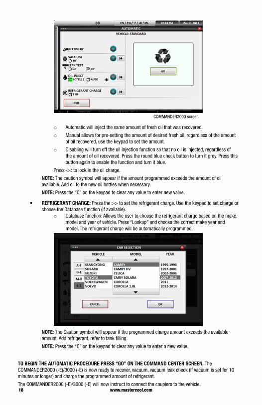
COMMANDER2000 (-E)/3000 (-E) AUTOMATIC PROCEDUREAUTOMATIC SCREEN SETTINGSThe COMMANDER2000 (-E)/3000 (-E) automatic screen will display: hose flushing (COMMANDER3000 (-E) only), recovery, vacuum, leak test, oil inject (COMMANDER2000 (-E), COMMANDER3000-E only) and refrigerant charge:
COMMANDER3000 screen
• HOSE FLUSH (COMMANDER3000 (-E) only): This process will flush the machine of any residual oil that is not compatible with hybrid R134a systems. Follow the instructions on the screen
1. Connect the red and blue hoses to the flush / storage fittings on the side of the machine. 2. Open the couplers by turning the knobs clockwise.3. Open the red and blue valves on the machine. Press next.4. The flush cycle will now be performed.5. Flush complete will be displayed when finished .6. Disconnect couplers and attach them to the vehicle AC system.
• RECOVERY: This procedure is preprogrammed. It cannot be changed in automatic mode.
• VACUUM: To set the desired amount of vacuum time, press the >> to the right. Set vacuum time on the keypad, press << to lock in time.
COMMANDER3000 screen
• LEAK TEST: Vacuum leak testing is available when the vacuum time is 10 minutes or longer. Set the amount of time the leak test will run. Set the time at which the leak test should start.
• OIL INJECT (COMMANDER2000 (-E), COMMANDER3000-E ONLY): Press the >> to set the desired amount of oil on the keypad. There are three options for oil injection:
18 www.mastercool.com
COMMANDER2000 screen
o Automatic will inject the same amount of fresh oil that was recovered.
o Manual allows for pre-setting the amount of desired fresh oil, regardless of the amount of oil recovered, use the keypad to set the amount.
o Disabling will turn off the oil injection function so that no oil is injected, regardless of the amount of oil recovered. Press the round blue check button to turn it grey. Press this button again to enable the function and turn it blue.
Press << to lock in the oil charge.
NOTE: The caution symbol will appear if the amount programmed exceeds the amount of oil available. Add oil to the new oil bottles when necessary.
NOTE: Press the “C” on the keypad to clear any value to enter new value.
• REFRIGERANT CHARGE: Press the >> to set the refrigerant charge. Use the keypad to set charge or choose the Database function (if available).
o Database function: Allows the user to choose the refrigerant charge based on the make, model and year of vehicle. Press “Lookup” and choose the correct make year and model. The refrigerant charge will be automatically programmed.
NOTE: The Caution symbol will appear if the programmed charge amount exceeds the available amount. Add refrigerant, refer to tank filling.
NOTE: Press the “C” on the keypad to clear any value to enter a new value.
TO BEGIN THE AUTOMATIC PROCEDURE PRESS “GO” ON THE COMMAND CENTER SCREEN. The COMMANDER2000 (-E)/3000 (-E) is now ready to recover, vacuum, vacuum leak check (if vacuum is set for 10 minutes or longer) and charge the programmed amount of refrigerant.
The COMMANDER2000 (-E)/3000 (-E) will now instruct to connect the couplers to the vehicle.

19www.mastercool.com
1. Connect the high side red coupler to the high side service fitting on the vehicle.2. Connect the low side blue coupler to the low side service fitting. Press next to continue. 3. Open the couplers by turning the knobs clockwise until they stop. Press next to continue.
4. Open the blue and red valves on the machine. Press next to start the process.
NOTE: Each step in the reclamation process will be displayed with individual progress screens.
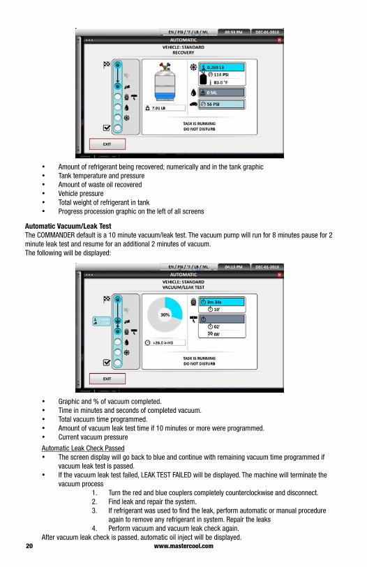
Automatic RecoveryThe following will be displayed:
20 www.mastercool.com
• Amount of refrigerant being recovered; numerically and in the tank graphic• Tank temperature and pressure• Amount of waste oil recovered • Vehicle pressure • Total weight of refrigerant in tank • Progress procession graphic on the left of all screens
Automatic Vacuum/Leak Test The COMMANDER default is a 10 minute vacuum/leak test. The vacuum pump will run for 8 minutes pause for 2 minute leak test and resume for an additional 2 minutes of vacuum.The following will be displayed:
• Graphic and % of vacuum completed.• Time in minutes and seconds of completed vacuum.• Total vacuum time programmed.• Amount of vacuum leak test time if 10 minutes or more were programmed.• Current vacuum pressure
Automatic Leak Check Passed• The screen display will go back to blue and continue with remaining vacuum time programmed if
vacuum leak test is passed. • If the vacuum leak test failed, LEAK TEST FAILED will be displayed. The machine will terminate the
vacuum process1. Turn the red and blue couplers completely counterclockwise and disconnect.2. Find leak and repair the system.3. If refrigerant was used to find the leak, perform automatic or manual procedure
again to remove any refrigerant in system. Repair the leaks4. Perform vacuum and vacuum leak check again.
After vacuum leak check is passed, automatic oil inject will be displayed.
21www.mastercool.com
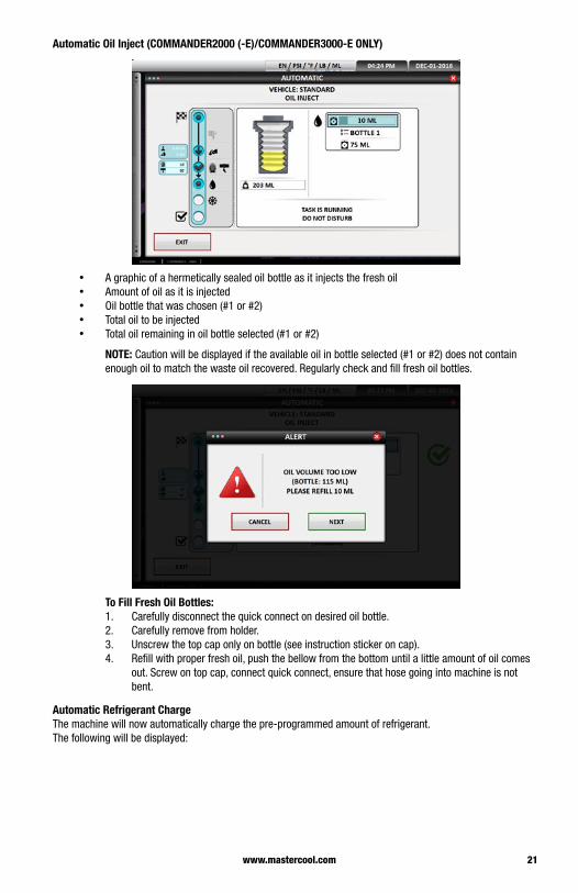
Automatic Oil Inject (COMMANDER2000 (-E)/COMMANDER3000-E ONLY)
• A graphic of a hermetically sealed oil bottle as it injects the fresh oil• Amount of oil as it is injected• Oil bottle that was chosen (#1 or #2)• Total oil to be injected• Total oil remaining in oil bottle selected (#1 or #2)
NOTE: Caution will be displayed if the available oil in bottle selected (#1 or #2) does not contain enough oil to match the waste oil recovered. Regularly check and fill fresh oil bottles.
To Fill Fresh Oil Bottles:1. Carefully disconnect the quick connect on desired oil bottle.2. Carefully remove from holder.3. Unscrew the top cap only on bottle (see instruction sticker on cap). 4. Refill with proper fresh oil, push the bellow from the bottom until a little amount of oil comes
out. Screw on top cap, connect quick connect, ensure that hose going into machine is not bent.
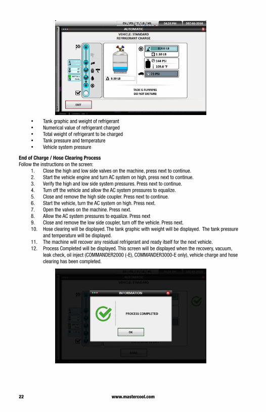
Automatic Refrigerant Charge The machine will now automatically charge the pre-programmed amount of refrigerant.The following will be displayed:
22 www.mastercool.com
• Tank graphic and weight of refrigerant• Numerical value of refrigerant charged • Total weight of refrigerant to be charged• Tank pressure and temperature • Vehicle system pressure
End of Charge / Hose Clearing ProcessFollow the instructions on the screen:
1. Close the high and low side valves on the machine, press next to continue. 2. Start the vehicle engine and turn AC system on high, press next to continue.3. Verify the high and low side system pressures. Press next to continue.4. Turn off the vehicle and allow the AC system pressures to equalize.5. Close and remove the high side coupler. Press next to continue.6. Start the vehicle, turn the AC system on high. Press next. 7. Open the valves on the machine. Press next.8. Allow the AC system pressures to equalize. Press next9. Close and remove the low side coupler, turn off the vehicle. Press next.10. Hose clearing will be displayed. The tank graphic with weight will be displayed. The tank pressure
and temperature will be displayed. 11. The machine will recover any residual refrigerant and ready itself for the next vehicle.12. Process Completed will be displayed. This screen will be displayed when the recovery, vacuum,
leak check, oil inject (COMMANDER2000 (-E), COMMANDER3000-E only), vehicle charge and hose clearing has been completed.

23www.mastercool.com
COMMANDER1000 (-E)/2000 (-E)/3000 (-E) MANUAL PROCEDURE Once manual is chosen, the machine will now display the screen where you can manually hose flush (COMMANDER3000 (-E) only), recover the refrigerant in the vehicle, pull a vacuum for the programmed amount of time, perform a vacuum leak check, inject oil (COMMANDER2000 (-E), COMMANDER3000-E only) or charge a programmed amount of refrigerant into the system. Each of these processes will be performed individually. As each function is completed, “process complete” will be displayed on the screen and the visual indicator light will turn green.
NOTE: All the machine to complete the process on its own. Terminating a process will cause the machine to work in an unpredictable way. Some maintenance might be required to restore the machine to proper working order.
Hose Flush (COMMANDER3000 (-E) HYBRID OPTION ONLY):1. Press the hose flushing button. Press go.2. Connect the couplers to the fittings on the side of the machine. Press next.3. Open the couplers by turning the knobs clockwise. Press next.4. Open machine valves. Press next.5. The hose flushing screen will now be displayed. The machine will use some of the refrigerant in the
internal tank to flush out the hoses. This process is used when switching from standard vehicle to hybrid vehicle. This process will ensure the removal of any non-compatible oil before working on a hybrid vehicle.
6. “Process complete” will be displayed when finished.
Recovery:1. Press the recovery button, press the GO button to start the refrigerant recovery.2. Follow the directions on the screen.3. Connect the couplers to the vehicle. Press next to continue.4. Open the couplers by turning the knob clockwise. Press next to continue.5. Open the machine valves. Press next to continue.6. The recovery screen will now be displayed. The screen will show the total amount of refrigerant in
the tank, the amount of refrigerant being recovered, the tank pressure and temperature, the amount of waste oil removed and the vehicle AC pressure.
7. When the recovery is complete “process complete” will be displayed.
Vacuum:1. Press the vacuum button.2. Use the keypad displayed to program in desired vacuum time. The vacuum is pre-programmed
for 10 minutes which includes a two minute vacuum leak check. If the vacuum leak check is not desired press the “C” button on the keypad to clear out time then program in the desired vacuum time. Press the double arrows to lock in the vacuum time.
3. Press the go button, follow the instructions on the screen. Connect the couplers to the vehicle, press next. Open the couplers by turning the knobs clockwise, press next. Open the Machine valves, press next.
4. The vacuum procedure will now be performed.
Oil Injection (COMMANDER2000 (-E), COMMANDER3000-E ONLY): NOTE: The vehicle will need to be under a full vacuum for the oil injection process to work.
1. Press the oil injection button.2. Program in the amount of oil desired to be charged into the vehicle. Press the arrows button to lock
in the charge.3. Press the go button. Follow the instructions on the screen. Connect the couplers to the vehicle, press
next. Open the couplers by turning the knobs clockwise, press next. Open the Machine valves, press next.
4. The programmed amount of oil will be injected.
Refrigerant Charge:1. Press the refrigerant charge button, use the keypad to program in the desired refrigerant charge.
You may also use the database option to look up the year make and model of the vehicle. Press the double arrows to lock in your selection. Press the go button.
2. Follow the instruction on the screen.
24 www.mastercool.com
3. Connect the couplers to the vehicle, press next.4. Open the couplers by turning them clockwise, press next.5. Open the Machine valves. Press next.6. The machine will now charge the programed amount of refrigerant. The Refrigerant charge
screen will be displayed. This screen will display the amount of refrigerant in the internal tank, the refrigerant being charged, the total amount of refrigerant programmed, the tank pressure, temperature and vehicle pressure. When the charge is finished “process complete” will be displayed and the visual indicator will turn green.
End of Charge / Hose Clearing Process:This process allows for the verification of the operating AC pressures and the removal of refrigerant from the hoses into the internal tank. The machine will then perform a short vacuum to prepare for the next vehicle. Follow the instruction on the screen.1. Close the high and low side valves on the machine, press next to continue. 2. Start the vehicle engine and turn AC system on high, press next to continue.3. Verify the high and low side system pressures. Press next to continue.4. Turn off the vehicle and allow the AC system pressures to equalize.5. Close and remove the high side coupler. Press next to continue.6. Start the vehicle, turn the AC system on high. Press next. 7. Open the valves on the machine. Press next.8. Allow the AC system pressures to equalize. Press next.9. Close and remove the low side coupler, turn off the vehicle. Press next.10. Hose clearing will be displayed. The tank graphic with weight will be displayed. The tank
pressure and temperature will be displayed. 11. The machine will recover any residual refrigerant and ready itself for the next vehicle.12. Process Completed, will be displayed when finished.
If you have difficulty with a procedure please call Mastercool’s Technical Service at 973-252-9119
69887-INST-R
WARNING: This product can expose you to chemicals including lead and Di (2-ethylhexyl) phthalate, which are known to the State of California to cause cancer and birth defects or other reproductive harm. For more information go to www.P65Warnings.ca.gov