PROJECT REPORT-RAHUL
45
JAMADOBA COAL PREPARATION PLANT, JHARIA DIVISION INDIAN SCHOOL OF MINES, DHANBAD A PROJECT REPORT ON PERFORMANCE ANALYSIS OF DENSE MEDIA CYCLONE JAMADOBA COAL PREPARATION PLANT JHARIA DIVISION DURATION -8 TH JUNE -20 TH JULY 2015 UNDER GUIDANCE OF- SUBMITTED BY- SHRI MANISH KUMAR RAHUL SINGH -2012JE1320 (SENIOR MANAGER, JCPP) Mineral Engg. (B.tech+M.tech) FUEL AND MINERAL ENGINEERING DEPARTMENT INDIAN SCHOOL OF MINES DHANBAD
-
Upload
rahul-singh -
Category
Documents
-
view
577 -
download
0
Transcript of PROJECT REPORT-RAHUL
JAMADOBA COAL PREPARATION PLANT, JHARIA DIVISION INDIAN SCHOOL OF MINES, DHANBAD
A PROJECT REPORT ON
PERFORMANCE ANALYSIS OF DENSE MEDIA CYCLONE
JAMADOBA COAL PREPARATION PLANT
JHARIA DIVISION
DURATION -8TH JUNE -20TH JULY 2015
UNDER GUIDANCE OF- SUBMITTED BY-
SHRI MANISH KUMAR RAHUL SINGH -2012JE1320
(SENIOR MANAGER, JCPP) Mineral Engg. (B.tech+M.tech)
FUEL AND MINERAL ENGINEERING DEPARTMENT INDIAN SCHOOL OF MINES DHANBAD
JAMADOBA COAL PREPARATION PLANT, JHARIA DIVISION INDIAN SCHOOL OF MINES, DHANBAD
TATA STEEL-PIONEER IN STEEL MANUFACTURING
ACKNOWLEDGEMENT
I wish to acknowledge the fuel and Mineral Engineering Department for giving the opportunity to conduct this Industrial training Project. I also acknowledge the support of Assistant Prof. Shri Pankaj kumar Jain (AP and Training-in charge) for this Industrial training Project. I hereby, take this opportunity to express my gratitude to all the people who have helped me in successfully completing my Industrial training project at Tata Steel, Jharia Division I express my gratitude to MR.SANJAY SINGH, (General Manager), Tata Steel Jharia Division for giving this opportunity to me. I wish to acknowledge the support of Mr G.S TIWARI (Training –in charge) JCPP I am highly indebted to Mr. PARTHA DAS, (Head JCPP), Tata Steel Jharia Division, for providing adequate facilities and guidance to complete my Industrial training Project. I wish to acknowledge the support of SHRI MANISH KUMAR (Senior Manager, JCPP) for this Industrial training Project I wish to acknowledge the support of SHRI MAHESH KUMAR ( Manager, JCPP) for this Industrial training Project I acknowledge the wonderful support of individuals numerous to mention by name-they
allowed us uninhibited access to their database for the success of the this Industrial training
Project
JAMADOBA COAL PREPARATION PLANT, JHARIA DIVISION INDIAN SCHOOL OF MINES, DHANBAD
TATA STEEL-PIONEER IN STEEL MANUFACTURING
SUMMARY
At JCPP coal from BCCL mines and Jharia division mines is been washed at ash 18%. The feed
coal of size-1000mm contain ash 30-37% which is first introduced to CHP section where sizing
and de-shaling is done in rotary breaker, from there it introduced to impact crusher and
scalping of feed take place. Finally feed coal of size-15mm is introduced to De-sliming screen of
0.5mm aperture, where+0.5mm is introduced to DM cyclone and -0.5mm is introduced to FF
section. DM cyclone separate clean coal at yield of 52.47% with an ash of 18-21% and reject
coal at yield of 23.28% with an ash of 50-60%.
Optimization of DM cyclone should be done and new digital techniques should be introduced
improve DM cyclone efficiency, proper visual checking of screen should be done so that it can
be checked that the oversize or undersize fraction is not exceeding it standard value, Moreover
proper checking of cyclone pressure should also be done in order to improve cyclone efficiency.
The magnetite media should have atleast 90% of -325mesh size fraction in media, it should be
checked in regular interval that so that proper size distribution.
2
JAMADOBA COAL PREPARATION PLANT, JHARIA DIVISION INDIAN SCHOOL OF MINES, DHANBAD
TATA STEEL-PIONEER IN STEEL MANUFACTURING
CONTENTS
1.0 CHAPTER ONE –INTRODUCTON
1.1 Introduction to Tata Steel and Jharia division.
1.2 About Jamadoba coal preparation plant (JCPP).
1.3 Quality Performance Report
1.4 Process Flow sheet
1.5 Process Description
1.6 Major Failure and Prevention
2.0 CHAPTER TWO- DENSE MEDIA CYCLONE
2.1 Introduction to DMC
2.2 Design and Separation Mechanism
2.3 Common Problem in DMC
2.4 Parameter effecting DMC performance
2.5 Performance Evolution
2.5.1 Efficiency of Separation
2.5.3 Major Failure Mode, Potential Cause and Prevention
2. 6 Separating Media
2.6.1 Major Losses
2.7 Dense Media cyclone Development and Different Models.
3.0 CONCLUSION
4.0 RECOMMENDATION
5.0 REFERENCE
3
JAMADOBA COAL PREPARATION PLANT, JHARIA DIVISION INDIAN SCHOOL OF MINES, DHANBAD
TATA STEEL-PIONEER IN STEEL MANUFACTURING
1.0 CHAPTER ONE - INTRODUCTION
1.1 INTRODUCTION TO TATA STEEL AND JHARIA DIVISON
TATA STEEL
Envisioned by the great patriot, Jamsetji Tata, and founded in 1907, Asia's first integrated private
sector steel company, Tata Steel Group is among the top-ten global steel companies with an annual
crude steel capacity of over 29 million tonnes per annum. It is now the world's second-most
geographically-diversified steel producer, with operations in 26 countries and a commercial presence
in over 50 countries. The Tata Steel Group, with a turnover of Rs. 1, 48,614 crores in FY 14, has over
80,000 employees across five continents and is a Fortune 500 company Tata Steel founded India’s
first industrial city, now Jamshedpur, where it established India’s first integrated steel plant in 1907.
The Jamshedpur Works currently comprises of a 9.7 mtpa crude steel production facility and a variety
of finishing mills.Two new Greenfield steel projects are planned in the states of Jharkhand and
Chhattisgarh. Kalinganagar project is underway, it is set to augment production capacity by 3 MnTPA
in the first phase. Mines and collieries in India give the Company a distinct advantage in raw material sourcing. Iron Ore mines are located at Noamundi (Jharkhand) and Joda (Odisha) both located within a distance of 150 km from Jamshedpur. The Company’s captive coal mines are located at Jharia and West Bokaro (Jharkhand) JHARIA DIVISION
Tata Steel is mining and beneficiating coal from Jharia Division since 1909. The division produces steel grade prime coking coal and clean it by beneficiation process at its two washeries – one at Jamadoba group and the other at Bhelatand group, supplying clean coal to Jamshedpur plant for coke making. The division comprises of five collieries, each nearly 100 years old spread over 5507.81 acres of leasehold areas in two locations 20km apart, namely Jamadoba group with Jamadoba Digwadih and 6&7 Pits collieries and Sijua group with Sijua, Malkera and Bhelatand collieries in it. The country’s Jharia collieries have extractable reserves of prime coking coal at depths of more than 600 metres.
JAMADOBA COAL PREPARATION PLANT, JHARIA DIVISION INDIAN SCHOOL OF MINES, DHANBAD
TATA STEEL-PIONEER IN STEEL MANUFACTURING
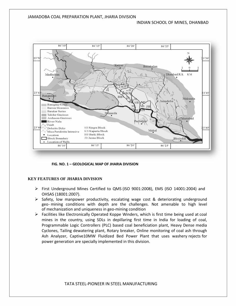
FIG. NO. 1 – GEOLOGICAL MAP OF JHARIA DIVISION KEY FEATURES OF JHARIA DIVISION
First Underground Mines Certified to QMS (ISO 9001:2008), EMS (ISO 14001:2004) and OHSAS (18001:2007).
Safety, low manpower productivity, escalating wage cost & deteriorating underground geo- mining conditions with depth are the challenges. Not amenable to high level of mechanization and uniqueness in geo-mining condition
Facilities like Electronically Operated Koppe Winders, which is first time being used at coal mines in the country, using SDLs in depillaring first time in India for loading of coal, Programmable Logic Controllers (PLC) based coal beneficiation plant, Heavy Dense media Cyclones, Tailing dewatering plant, Rotary breaker, Online monitoring of coal ash through Ash Analyzer, Captive10MW Fluidized Bed Power Plant that uses washery rejects for power generation are specially implemented in this division.
JAMADOBA COAL PREPARATION PLANT, JHARIA DIVISION INDIAN SCHOOL OF MINES, DHANBAD
TATA STEEL-PIONEER IN STEEL MANUFACTURING
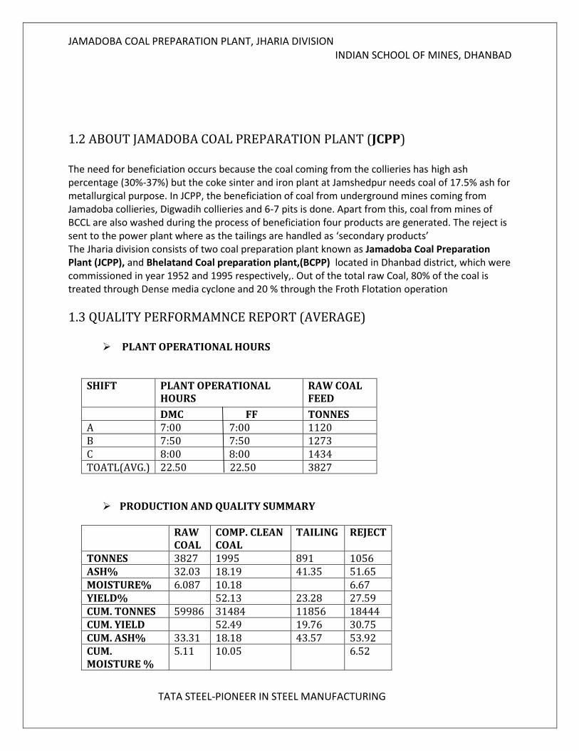
1.2 ABOUT JAMADOBA COAL PREPARATION PLANT (JCPP)
The need for beneficiation occurs because the coal coming from the collieries has high ash percentage (30%-37%) but the coke sinter and iron plant at Jamshedpur needs coal of 17.5% ash for metallurgical purpose. In JCPP, the beneficiation of coal from underground mines coming from Jamadoba collieries, Digwadih collieries and 6-7 pits is done. Apart from this, coal from mines of BCCL are also washed during the process of beneficiation four products are generated. The reject is sent to the power plant where as the tailings are handled as ‘secondary products’ The Jharia division consists of two coal preparation plant known as Jamadoba Coal Preparation Plant (JCPP), and Bhelatand Coal preparation plant,(BCPP) located in Dhanbad district, which were commissioned in year 1952 and 1995 respectively,. Out of the total raw Coal, 80% of the coal is treated through Dense media cyclone and 20 % through the Froth Flotation operation
1.3 QUALITY PERFORMAMNCE REPORT (AVERAGE)
PLANT OPERATIONAL HOURS
SHIFT PLANT OPERATIONAL HOURS
RAW COAL FEED
DMC FF TONNES A 7:00 7:00 1120 B 7:50 7:50 1273 C 8:00 8:00 1434 TOATL(AVG.) 22.50 22.50 3827
PRODUCTION AND QUALITY SUMMARY
RAW COAL
COMP. CLEAN COAL
TAILING REJECT
TONNES 3827 1995 891 1056 ASH% 32.03 18.19 41.35 51.65 MOISTURE% 6.087 10.18 6.67 YIELD% 52.13 23.28 27.59 CUM. TONNES 59986 31484 11856 18444 CUM. YIELD 52.49 19.76 30.75 CUM. ASH% 33.31 18.18 43.57 53.92 CUM. MOISTURE %
5.11 10.05 6.52
JAMADOBA COAL PREPARATION PLANT, JHARIA DIVISION INDIAN SCHOOL OF MINES, DHANBAD
TATA STEEL-PIONEER IN STEEL MANUFACTURING
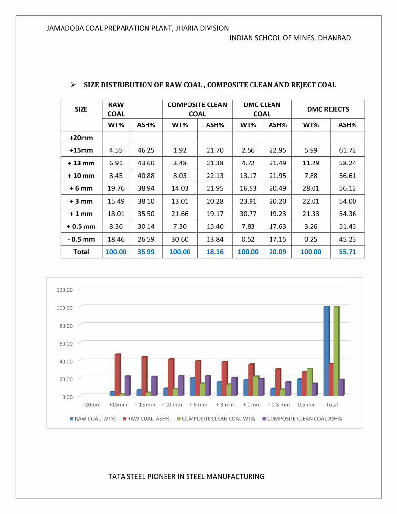
SIZE DISTRIBUTION OF RAW COAL , COMPOSITE CLEAN AND REJECT COAL
SIZE RAW COAL
COMPOSITE CLEAN
COAL DMC CLEAN
COAL DMC REJECTS
WT% ASH% WT% ASH% WT% ASH% WT% ASH%
+20mm
+15mm 4.55 46.25 1.92 21.70 2.56 22.95 5.99 61.72
+ 13 mm 6.91 43.60 3.48 21.38 4.72 21.49 11.29 58.24
+ 10 mm 8.45 40.88 8.03 22.13 13.17 21.95 7.88 56.61
+ 6 mm 19.76 38.94 14.03 21.95 16.53 20.49 28.01 56.12
+ 3 mm 15.49 38.10 13.01 20.28 23.91 20.20 22.01 54.00
+ 1 mm 18.01 35.50 21.66 19.17 30.77 19.23 21.33 54.36
+ 0.5 mm 8.36 30.14 7.30 15.40 7.83 17.63 3.26 51.43
- 0.5 mm 18.46 26.59 30.60 13.84 0.52 17.15 0.25 45.23
Total 100.00 35.99 100.00 18.16 100.00 20.09 100.00 55.71
0.00
20.00
40.00
60.00
80.00
100.00
120.00
+20mm +15mm + 13 mm + 10 mm + 6 mm + 3 mm + 1 mm + 0.5 mm - 0.5 mm Total
RAW COAL WT% RAW COAL ASH% COMPOSITE CLEAN COAL WT% COMPOSITE CLEAN COAL ASH%
JAMADOBA COAL PREPARATION PLANT, JHARIA DIVISION INDIAN SCHOOL OF MINES, DHANBAD
TATA STEEL-PIONEER IN STEEL MANUFACTURING
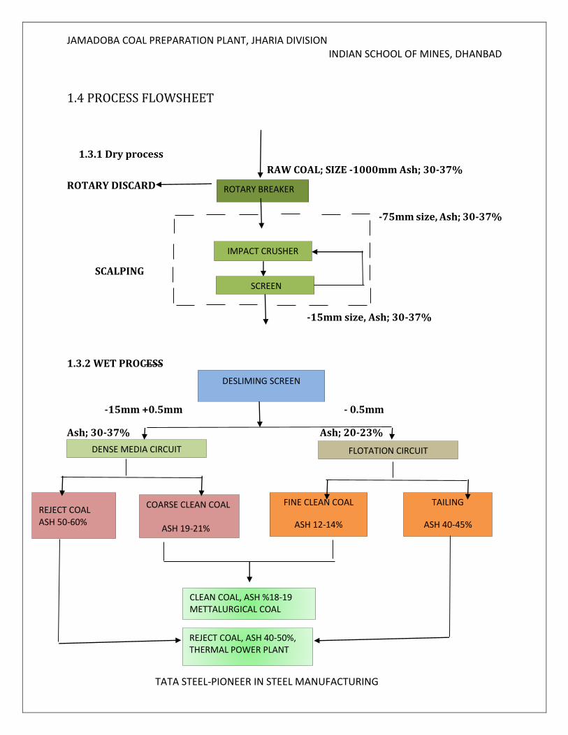
1.4 PROCESS FLOWSHEET 1.3.1 Dry process
RAW COAL; SIZE -1000mm Ash; 30-37%
ROTARY DISCARD
-75mm size, Ash; 30-37%
SCALPING
-15mm size, Ash; 30-37%
1.3.2 WET PROCESS
-15mm +0.5mm - 0.5mm
Ash; 30-37% Ash; 20-23%
ROTARY BREAKER
IMPACT CRUSHER
DESLIMING SCREEN
DENSE MEDIA CIRCUIT FLOTATION CIRCUIT
COARSE CLEAN COAL ASH 19-21%
FINE CLEAN COAL
ASH 12-14%
TAILING
ASH 40-45%
REJECT COAL ASH 50-60%
CLEAN COAL, ASH %18-19 METTALURGICAL COAL
REJECT COAL, ASH 40-50%, THERMAL POWER PLANT
SCREEN
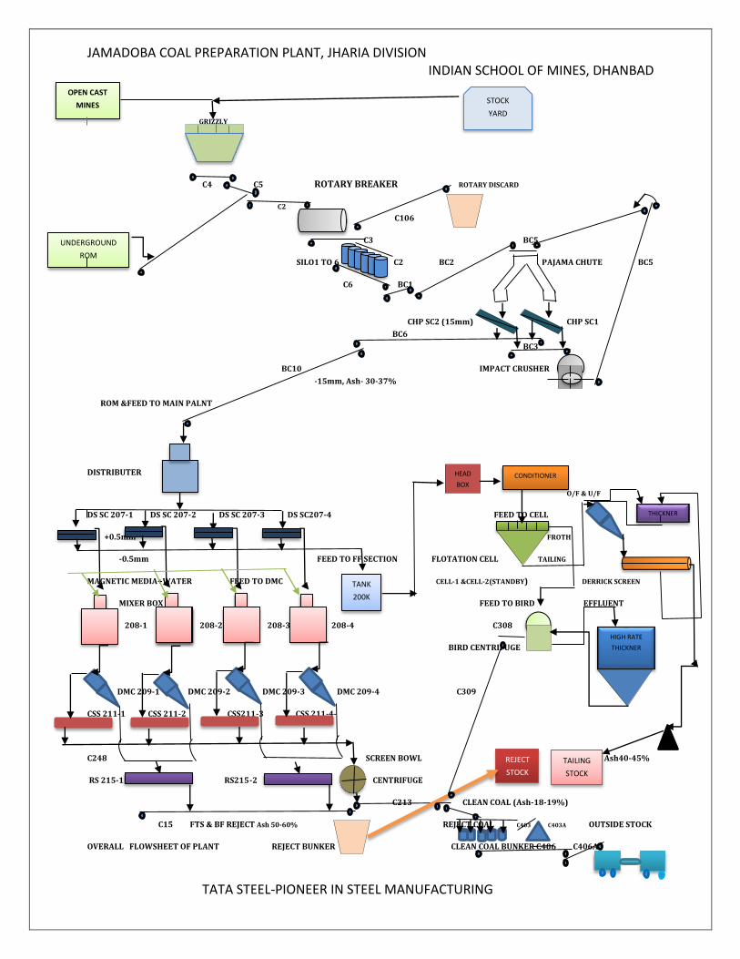
JAMADOBA COAL PREPARATION PLANT, JHARIA DIVISION INDIAN SCHOOL OF MINES, DHANBAD
TATA STEEL-PIONEER IN STEEL MANUFACTURING
GRIZZLY
C4 C5 ROTARY BREAKER ROTARY DISCARD
C2 C106
C3 BC5
SILO1 TO 6 C2 BC2 PAJAMA CHUTE BC5
C6 BC1
CHP SC2 (15mm) CHP SC1
BC6
BC3
BC10 IMPACT CRUSHER
-15mm, Ash- 30-37%
ROM &FEED TO MAIN PALNT
DISTRIBUTER
O/F & U/F
DS SC 207-1 DS SC 207-2 DS SC 207-3 DS SC207-4 FEED TO CELL
+0.5mm FROTH
-0.5mm FEED TO FF SECTION FLOTATION CELL TAILING
MAGNETIC MEDIA+WATER FEED TO DMC CELL-1 &CELL-2(STANDBY) DERRICK SCREEN
MIXER BOX FEED TO BIRD EFFLUENT
208-1 208-2 208-3 208-4 C308
BIRD CENTRIFUGE
DMC 209-1 DMC 209-2 DMC 209-3 DMC 209-4 C309
CSS 211-1 CSS 211-2 CSS211-3 CSS 211-4-
C248 SCREEN BOWL Ash40-45%
RS 215-1 RS215-2 CENTRIFUGE
C213 CLEAN COAL (Ash-18-19%)
C15 FTS & BF REJECT Ash 50-60% REJECT COAL C403 C403A OUTSIDE STOCK
OVERALL FLOWSHEET OF PLANT REJECT BUNKER CLEAN COAL BUNKER C406 C406A
OPEN CAST
MINES STOCK
YARD
UNDERGROUND
ROM
TANK
200K
HEAD
BOX CONDITIONER
THICKNER
HIGH RATE
THICKNER
REJECT
STOCK
TAILING
STOCK
JAMADOBA COAL PREPARATION PLANT, JHARIA DIVISION INDIAN SCHOOL OF MINES, DHANBAD
TATA STEEL-PIONEER IN STEEL MANUFACTURING
1.4 PROCESS DESCRIPTION
The whole Jamadoba coal preparation plant consists of three sections which are as follows: 1. Coal Handling Plant (CHP) 2. Coarse Coal Circuit
3. Fine Coal Circuit
1. COAL HANDLING PLANT (CHP)
In this unit, the coal received from the collieries by means of conveyor belts and trucks undergo primary crushing in a rotary breaker. It produces coal of -75mm which are then stored in bunker. There are six bunkers each of 100 ton capacity. The coals from the bunker go to scalping screens. There are two scalping screens. The undersize of the screens i.e. -15 mm is feed of the main plant where as the oversize undergoes
secondary cruising in the impactor. The product from the impactor is recirculates back to the screens.
TRUCK DUMP HOPPER:-
The run of mine coal with segments less than 1000 mm in size is dumped from a truck dump hopper or a belt network to a belt conveyer. The coal processed in Jamadoba Washery comes from Jamadoba, 6 & 7 pits and Digwadih (with ash percentage of 24 to 27%).
The truck sample is held in a triangular kiln known as ‘tippler’. The raw coal passes through the screens in the tippler and then goes to rotary breaker
ROTARY BREAKER:-
Rotary Breakers are used to break the coal to a predetermined size and remove rock. It is mostly used by the coal washery plants. From here coal segments less than 75 mm in dimensions are allowed to pass to primary scalping screen. The rest goes to the stone bunker.
The rotary principle has the advantage of very low fines production because
undersize coal is immediately screened out. The residual contaminants will get
segregated by the Rotary Breaker which operates on the principle that coal being
lighter will break and get segregated by centrifugal force of the rotary breaker and
pass through the screen inside the Rotary Breaker. Hard stone and shale will not
break under same speed and centrifugal force and hence will be discharged through
the reject chute of the Rotary Breaker.
Length of rotary breaker = 11 feet
Diameter of rotary breaker = 12 feet
Speed of rotary breaker =16.49 rpm (approx.)
Motor speed = 985 rpm Motor drive = 100 h p V-belt = D 328
JAMADOBA COAL PREPARATION PLANT, JHARIA DIVISION INDIAN SCHOOL OF MINES, DHANBAD
TATA STEEL-PIONEER IN STEEL MANUFACTURING
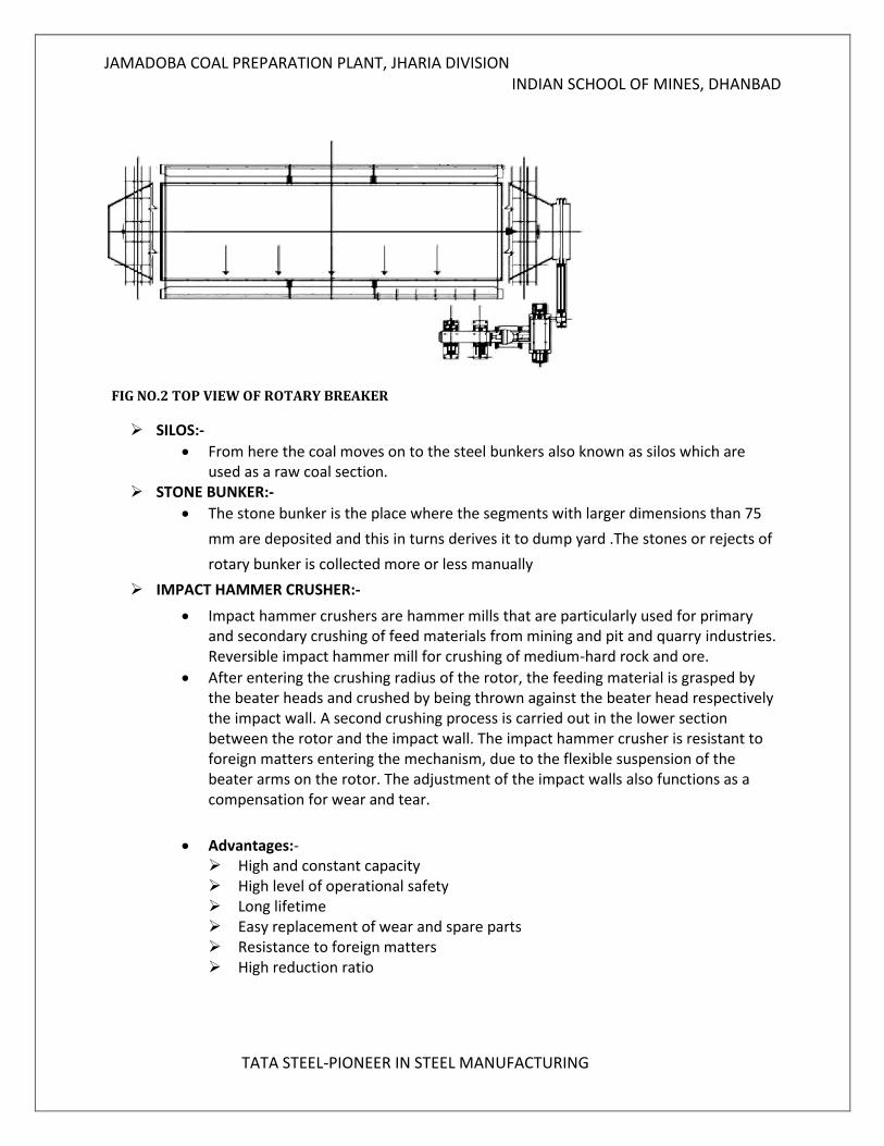
FIG NO.2 TOP VIEW OF ROTARY BREAKER
SILOS:-
From here the coal moves on to the steel bunkers also known as silos which are used as a raw coal section.
STONE BUNKER:-
The stone bunker is the place where the segments with larger dimensions than 75
mm are deposited and this in turns derives it to dump yard .The stones or rejects of
rotary bunker is collected more or less manually
IMPACT HAMMER CRUSHER:-
Impact hammer crushers are hammer mills that are particularly used for primary and secondary crushing of feed materials from mining and pit and quarry industries. Reversible impact hammer mill for crushing of medium-hard rock and ore.
After entering the crushing radius of the rotor, the feeding material is grasped by the beater heads and crushed by being thrown against the beater head respectively the impact wall. A second crushing process is carried out in the lower section between the rotor and the impact wall. The impact hammer crusher is resistant to foreign matters entering the mechanism, due to the flexible suspension of the beater arms on the rotor. The adjustment of the impact walls also functions as a compensation for wear and tear.
Advantages:-
High and constant capacity High level of operational safety Long lifetime Easy replacement of wear and spare parts Resistance to foreign matters High reduction ratio
JAMADOBA COAL PREPARATION PLANT, JHARIA DIVISION INDIAN SCHOOL OF MINES, DHANBAD
TATA STEEL-PIONEER IN STEEL MANUFACTURING
DESLIMING SCREEN:-
In -15x20 mm sized coal, water is seeped through at a very high speed into it. The mixture of coal and water runs through the distributer bands and falls on de-sliming screens and separates the particles on the basis of size. Thus the particle is separated into -15+0.5 mm and -0.5 mm sized coal.
The undersize (of size -0.5mm) is sent to the fines section or fine coal circuit.
The oversize (of size-15+0.5mm) coarse coal circuit
2. COARSE COAL CIRCUIT
There are mainly three section in coarse coal circuit
DISTRIBUTION AND DESLIMING SECTION
CYCLONE SECTION
MEDIA RECOVERY SECTION
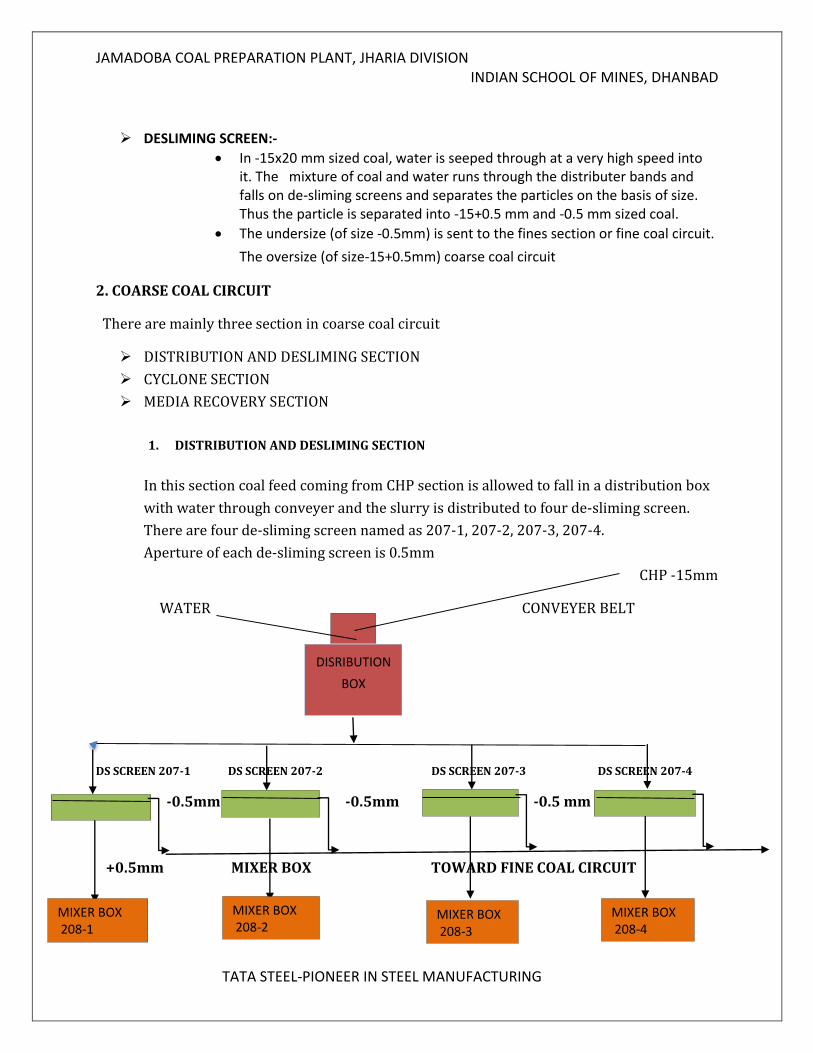
1. DISTRIBUTION AND DESLIMING SECTION
In this section coal feed coming from CHP section is allowed to fall in a distribution box
with water through conveyer and the slurry is distributed to four de-sliming screen.
There are four de-sliming screen named as 207-1, 207-2, 207-3, 207-4.
Aperture of each de-sliming screen is 0.5mm
CHP -15mm
WATER CONVEYER BELT
DS SCREEN 207-1 DS SCREEN 207-2 DS SCREEN 207-3 DS SCREEN 207-4
-0.5mm -0.5mm -0.5 mm
+0.5mm MIXER BOX TOWARD FINE COAL CIRCUIT
DISRIBUTION
BOX
MIXER BOX 208-1
MIXER BOX 208-4
MIXER BOX 208-3
MIXER BOX 208-2
JAMADOBA COAL PREPARATION PLANT, JHARIA DIVISION INDIAN SCHOOL OF MINES, DHANBAD
TATA STEEL-PIONEER IN STEEL MANUFACTURING
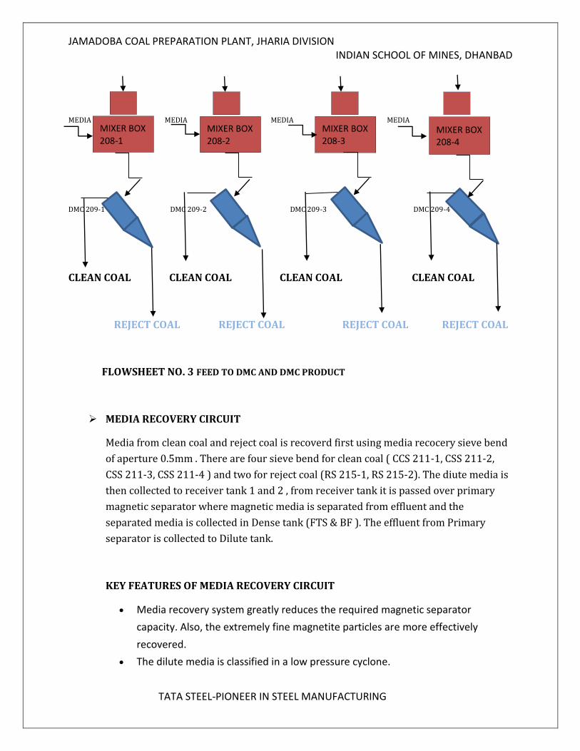
CYCLONE SECTION
In Cyclone section there are four dense media cyclone named as DMC 209-1,
DMC 209-2, DMC 209-3, DMC 209-4. The coal feed coming from de-sliming screen
(+0.5mm) in allowed to fall in mixer box where fresh separating media (Magnetite ) in
mix with coal and a mixer is prepared which is gravity fed to DMC cyclone. The overflow
(size -15+0.5 mm) is now sent to four Mixer Boxes. In the mixer boxes the coal is mixed with
a media made up of Fe3O4 (Magnetite) suspension in water. This mixture is now sent into
four Dense Media Cyclones (DMC) where separation takes place at specific gravity of about
1.50. The overflow is composed of particles of specific gravity less than 1.50while the
underflow is made up of particles of specific gravity more than 1.50. The overflow is now of
ash content of about 18-19% and is considered as Washed Coal. The underflow is high in ash
content, about 45-55%. The underflow is thus considered to be Reject.
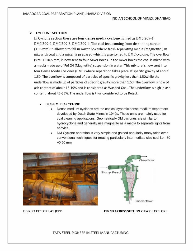
DENSE MEDIA CYCLONE
Dense medium cyclones are the conical dynamic dense medium separators
developed by Dutch State Mines in 1940s. These units are mainly used for
coal cleaning applications. Geometrically DM cyclones are similar to
hydrocyclone and generally use magnetite as a media to separate lights from
heavies.
DM Cyclone operation is very simple and gained popularity many folds over
conventional techniques for treating particularly intermediate size coal i.e. -50
+0.50 mm
FIG.NO.3 CYCLONE AT JCPP FIG.NO.4 CROSS SECTION VIEW OF CYCLONE
JAMADOBA COAL PREPARATION PLANT, JHARIA DIVISION INDIAN SCHOOL OF MINES, DHANBAD
TATA STEEL-PIONEER IN STEEL MANUFACTURING
MEDIA MEDIA MEDIA MEDIA
DMC 209-1 DMC 209-2 DMC 209-3 DMC 209-4
CLEAN COAL CLEAN COAL CLEAN COAL CLEAN COAL
REJECT COAL REJECT COAL REJECT COAL REJECT COAL
FLOWSHEET NO. 3 FEED TO DMC AND DMC PRODUCT
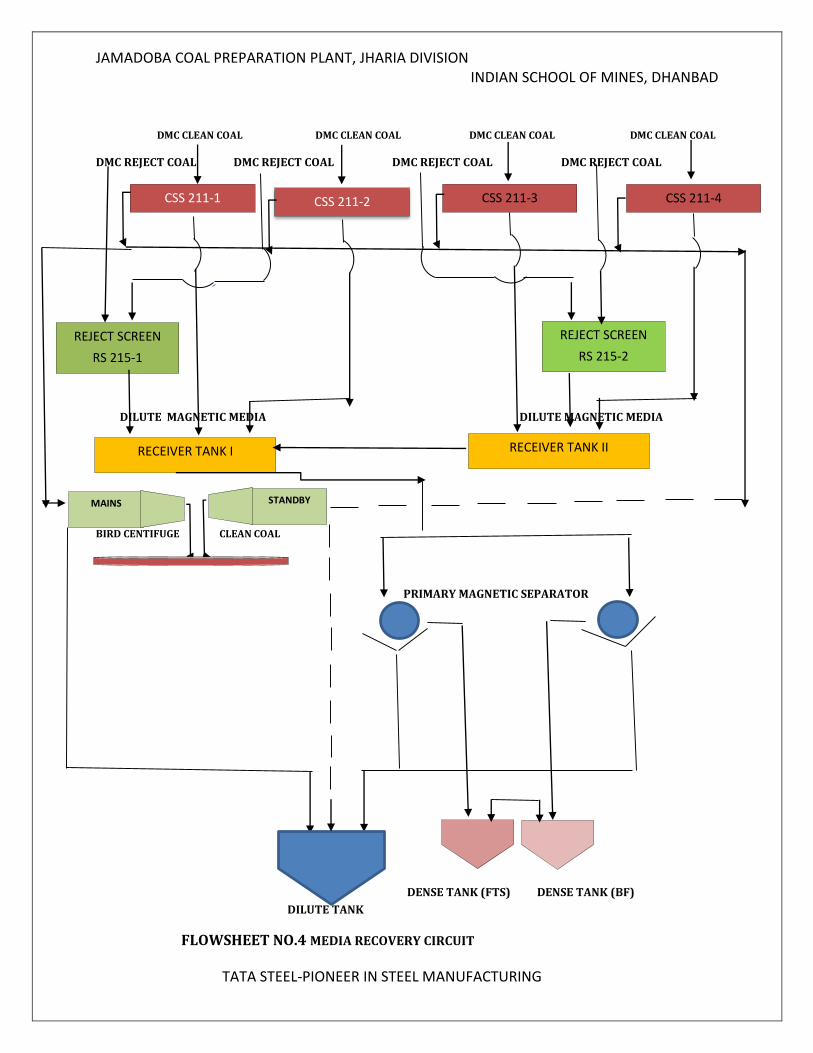
MEDIA RECOVERY CIRCUIT
Media from clean coal and reject coal is recoverd first using media recocery sieve bend
of aperture 0.5mm . There are four sieve bend for clean coal ( CCS 211-1, CSS 211-2,
CSS 211-3, CSS 211-4 ) and two for reject coal (RS 215-1, RS 215-2). The diute media is
then collected to receiver tank 1 and 2 , from receiver tank it is passed over primary
magnetic separator where magnetic media is separated from effluent and the
separated media is collected in Dense tank (FTS & BF ). The effluent from Primary
separator is collected to Dilute tank.
KEY FEATURES OF MEDIA RECOVERY CIRCUIT
Media recovery system greatly reduces the required magnetic separator
capacity. Also, the extremely fine magnetite particles are more effectively
recovered.
The dilute media is classified in a low pressure cyclone.
MIXER BOX 208-1
MIXER BOX 208-2
MIXER BOX 208-3
MIXER BOX 208-4
JAMADOBA COAL PREPARATION PLANT, JHARIA DIVISION INDIAN SCHOOL OF MINES, DHANBAD
TATA STEEL-PIONEER IN STEEL MANUFACTURING
The coarse magnetite in the underflow is fed to a magnetic separetor which
concentrates the magnetite and removes the nonmagnetic. This magnetite
concentrate also flows to the static thickner.
The magnetite particles settle rapidly to the bottom of the thickner because their high
magnetic charge causes them to form strong flocs. This thickned magnetite is then fed
to the medium sump at a rate generally determined by an automatic mediam specific
gravity control system.
The thickner overflow, which contain only a few grams of magnetite per gallonn, is used
for rising the cyclone products.
The concentration of magnetite in the dilute medium may become high enough to
couse the cyclone classifier to act as a dense medim cyclone. Low specific gravity coal
particles then report to the cyclone classifier overflow, settle to the bottom of the
thickner, and discharge with the thickner overflow.
High concentration of the material lowers the specific gravity of the thickner underflow,
which in turn may cause difficulty in maintaining the specific gravity of the dense
medium.
JAMADOBA COAL PREPARATION PLANT, JHARIA DIVISION INDIAN SCHOOL OF MINES, DHANBAD
TATA STEEL-PIONEER IN STEEL MANUFACTURING
DMC CLEAN COAL DMC CLEAN COAL DMC CLEAN COAL DMC CLEAN COAL
DMC REJECT COAL DMC REJECT COAL DMC REJECT COAL DMC REJECT COAL
c
DILUTE MAGNETIC MEDIA DILUTE MAGNETIC MEDIA
B
BIRD CENTIFUGE CLEAN COAL
PRIMARY MAGNETIC SEPARATOR
DENSE TANK (FTS) DENSE TANK (BF)
DILUTE TANK
FLOWSHEET NO.4 MEDIA RECOVERY CIRCUIT
CSS 211-1 CSS 211-4 CSS 211-3 CSS 211-2
REJECT SCREEN
RS 215-1
REJECT SCREEN
RS 215-2
RECEIVER TANK I RECEIVER TANK II
MAINS STANDBY
JAMADOBA COAL PREPARATION PLANT, JHARIA DIVISION INDIAN SCHOOL OF MINES, DHANBAD
TATA STEEL-PIONEER IN STEEL MANUFACTURING
3.0 FINE COAL CIRCUIT
The fines section coal of below 0.5mm, which comes from the underflow of de-sliming screen, is processed. It consists of three Water only Cyclones and two Froth Flotation cells. Recently cyclones have been stopped in action and only flotation cells are taken into process for the purpose of beneficiation. Input to fines circuit is the underflow of de-sliming screen (207-1, 2, 3, 4). The fines coming from underflow of de-sliming screen has size –0.5mm and of ash percentage 21%-24%.
The underflow of de-sliming screens is taken first to 200k tank sump from where it is pumped to head box. From head box the slurry is taken to two conditioners which take it to two flotation cell (A & B) each containing 4 compartments Presently the quantity of collector and frother added is 20cc/min and 200cc/min respectively. The slurry in flotation chambers is agitated with the help of a rotor-stator assembly and air is flown as per requirement. The froth formed is collected out continuously with the help of paddles and is taken into froth launder from where it is taken to centrifuge for the process of dewatering. The tailings are taken out by automatic valve or manual valve and are taken to tailing thickener.
In the thickener the tailings got settled down owing to the principle of sedimentation and are taken out through pump and are sent to tailing ponds from where after settling, tailings are taken out and sent through trucks. The overflow of tailing thickener is clarified water which is further reused in the plant.
The froth from flotation cell is sent to screen bowl centrifuge (manufactured by Bird) for the dewatering purpose. It consists of a horizontal revolving shell or bowl inside which a screw conveyor of similar section rotates in the same direction at a slightly lower speed. The feed pulp is admitted to bowl through the centre tube of revolving screw conveyor. On leaving the feed pipe the slurry is immediately subjected to high centrifugal force causing the solids to settle on the inner surface of the bowl at a rate which depends on the rotational speed employed. Here the bowl is revolved at speed 1000 rpm. The product of the centrifuge is the dry clean coal (ash=14.5%), effluent and port. The clean coal obtained here has moisture
around 20%. It has been found that effluent carries ultra-fines of low ash content.. The clean coal obtained from screen bowl centrifuge is mixed with the clean coal coming
from main plant. The ash percentage of composite coal is 18.0% which is then sent to
Jamshedpur
JAMADOBA COAL PREPARATION PLANT, JHARIA DIVISION INDIAN SCHOOL OF MINES, DHANBAD
TATA STEEL-PIONEER IN STEEL MANUFACTURING
STUDY OF DIFFERENT UNITS OF FINES CIRCUIT
1. Head box:-
The underflow of de-sliming screens of size -0.5mm is taken first to 200k tank sump from where it is pumped to head box. Head Box has three chambers. The feed is falling from the pipe on the middle chamber and the two chambers are there to provide feed to both the flotation panels A and B. Each flotation panel contains 4 flotation cells.
2. Water only cyclone:- From the main feed pipe coming from the 200k tank sump, a valve is there and from there another pipe is placed to supply feed to the water only cyclone. The under flow of cyclone is taken to the conditioning tank of flotation cells of A. The overflow of the cyclone is taken directly to the froth launder of the flotation cell A. There are 3 cyclones out of which one was running but recently cyclones have been stopped in action and only flotation cells are taken into process for the purpose of beneficiation.
3. Conditioning tank:- ` Both the flotation panels A & B consisting four flotation cells, each panel is having two
different conditioning tanks for the feed. In conditioning tank feed is allowed to mix with reagent i.e. collector. Collector is added in conditioning tank and provided with sufficient conditioning time which is very important for flotation. Conditioning tank is also having an agitator for the proper mixing of feed and collector. Collector used here is diesel and its dosage is 200ml/min. Main function of collector is to promote contact between coal particles and air bubbles by forming a thin layer/coating over the particle to be floated
4. Flotation cell In JCPP, Mechanical flotation machines are used with two parallel flotation banks A & B, each of four flotation cells. Flotation cell gets feed from the feed launder. Flotation cell consists of agitator rotating at certain rpm and air introduction pipe which gets into agitator by a hollow pipe and air is introduced at the bottom of the cell and distributed with agitator forming suspension. Volume of the cell is 8.5m3. Air is controlled depending upon the product quality.
5. Screen bowl centrifuge:- The froth from flotation cell is sent to screen bowl centrifuge (manufactured by Bird) for the dewatering purpose. It consists of a horizontal revolving shell or bowl inside which a screw conveyor of similar section rotates in the same direction at a slightly lower speed. The feed pulp is admitted to bowl through the center tube of revolving screw conveyor. On leaving the feed pipe the slurry is immediately subjected to high centrifugal force causing the solids to settle on the inner surface of the bowl at a rate which depends on the rotational speed employed.
6. High rate thickener:- Effluent and port of Bird centrifuge which mainly contains ultra-fines (-300mesh) are sent to high rate thickener. The thickener is used to increase the concentration of suspension by sedimentation, accompanied by the formation of clear liquid. The underflow of HRT is sent back to centrifuge for
JAMADOBA COAL PREPARATION PLANT, JHARIA DIVISION INDIAN SCHOOL OF MINES, DHANBAD
TATA STEEL-PIONEER IN STEEL MANUFACTURING
dewatering. The diameter of HRT is 12m and flocculants are used to increase the sedimentation of particles. One of the problems is that sedimentation of particles in HRT is not effective and ultra-fines are coming in overflow.
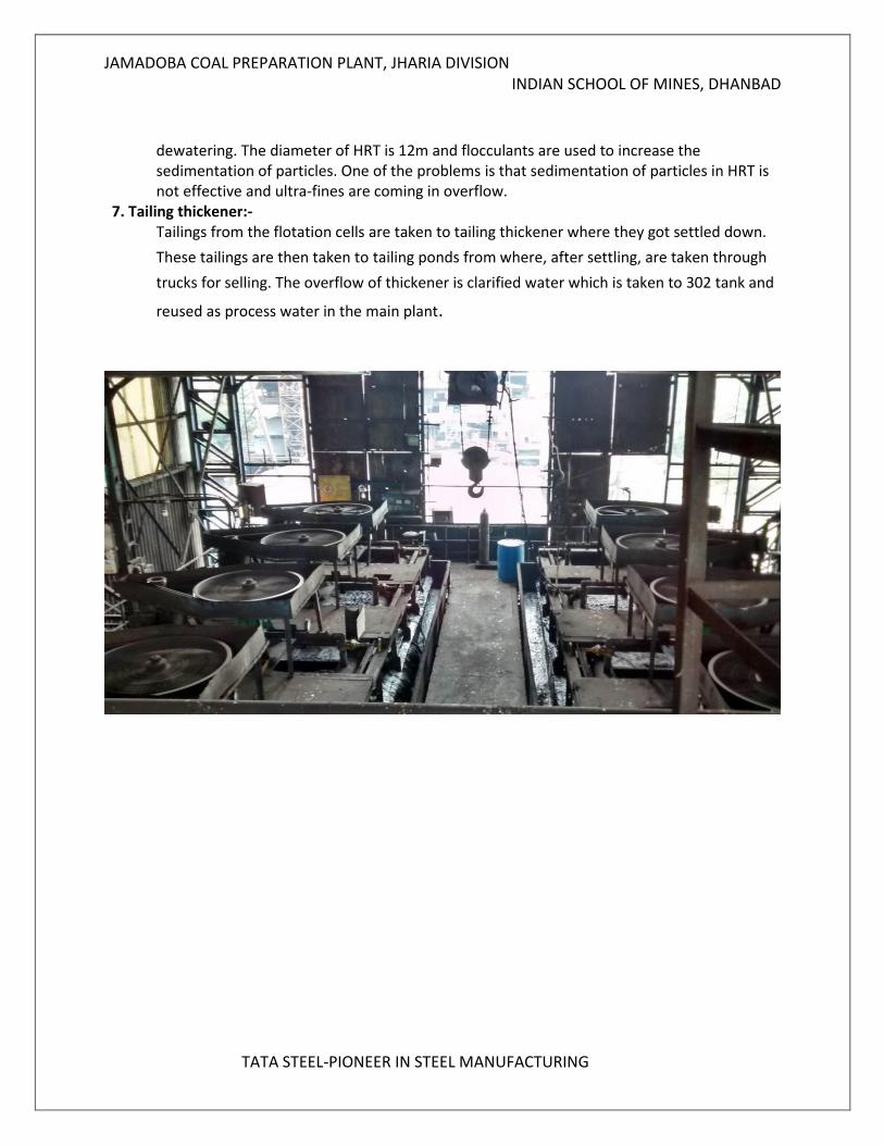
7. Tailing thickener:- Tailings from the flotation cells are taken to tailing thickener where they got settled down.
These tailings are then taken to tailing ponds from where, after settling, are taken through
trucks for selling. The overflow of thickener is clarified water which is taken to 302 tank and
reused as process water in the main plant.
JAMADOBA COAL PREPARATION PLANT, JHARIA DIVISION INDIAN SCHOOL OF MINES, DHANBAD
TATA STEEL-PIONEER IN STEEL MANUFACTURING
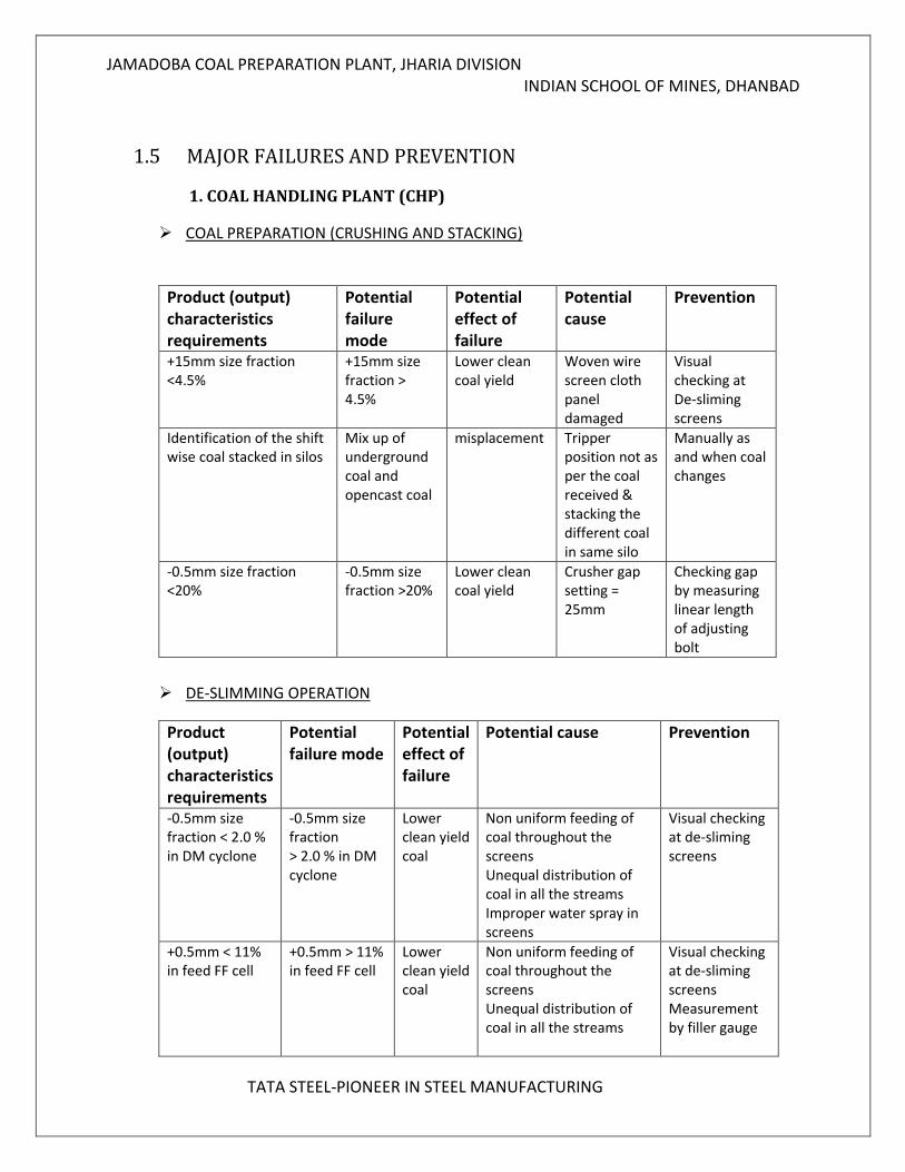
1.5 MAJOR FAILURES AND PREVENTION
1. COAL HANDLING PLANT (CHP)
COAL PREPARATION (CRUSHING AND STACKING)
Product (output) characteristics requirements
Potential failure mode
Potential effect of failure
Potential cause
Prevention
+15mm size fraction <4.5%
+15mm size fraction > 4.5%
Lower clean coal yield
Woven wire screen cloth panel damaged
Visual checking at De-sliming screens
Identification of the shift wise coal stacked in silos
Mix up of underground coal and opencast coal
misplacement Tripper position not as per the coal received & stacking the different coal in same silo
Manually as and when coal changes
-0.5mm size fraction <20%
-0.5mm size fraction >20%
Lower clean coal yield
Crusher gap setting = 25mm
Checking gap by measuring linear length of adjusting bolt
DE-SLIMMING OPERATION
Product (output) characteristics requirements
Potential failure mode
Potential effect of failure
Potential cause Prevention
-0.5mm size fraction < 2.0 % in DM cyclone
-0.5mm size fraction > 2.0 % in DM cyclone
Lower clean yield coal
Non uniform feeding of coal throughout the screens Unequal distribution of coal in all the streams Improper water spray in screens
Visual checking at de-sliming screens
+0.5mm < 11% in feed FF cell
+0.5mm > 11% in feed FF cell
Lower clean yield coal
Non uniform feeding of coal throughout the screens Unequal distribution of coal in all the streams
Visual checking at de-sliming screens Measurement by filler gauge
JAMADOBA COAL PREPARATION PLANT, JHARIA DIVISION INDIAN SCHOOL OF MINES, DHANBAD
TATA STEEL-PIONEER IN STEEL MANUFACTURING
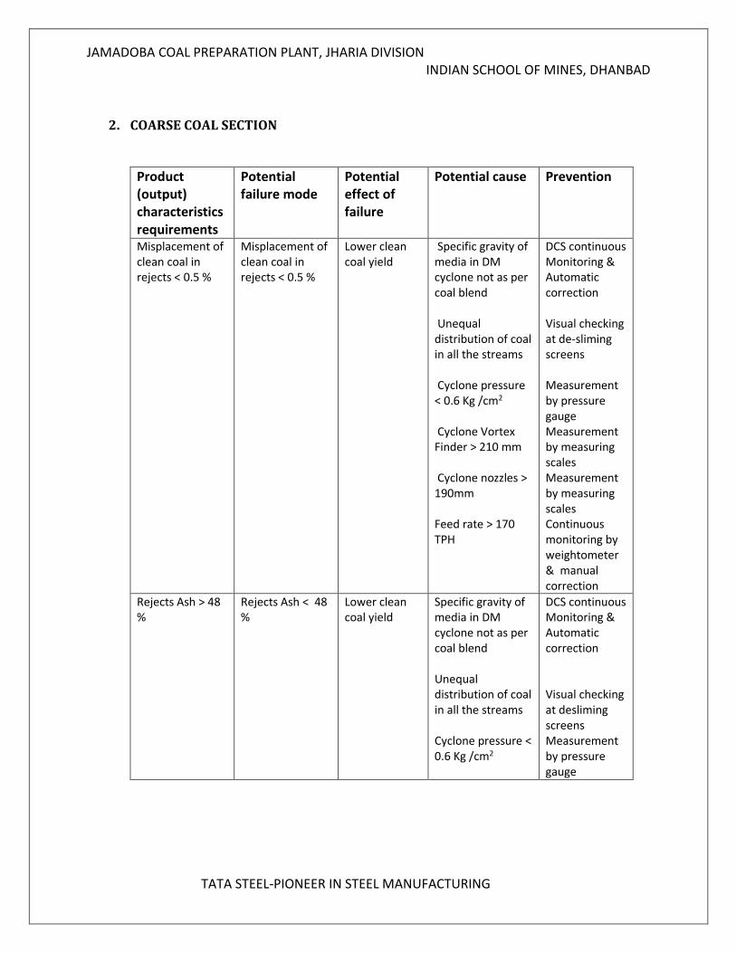
2. COARSE COAL SECTION
Product (output) characteristics requirements
Potential failure mode
Potential effect of failure
Potential cause Prevention
Misplacement of clean coal in rejects < 0.5 %
Misplacement of clean coal in rejects < 0.5 %
Lower clean coal yield
Specific gravity of media in DM cyclone not as per coal blend Unequal distribution of coal in all the streams Cyclone pressure < 0.6 Kg /cm2 Cyclone Vortex Finder > 210 mm Cyclone nozzles > 190mm Feed rate > 170 TPH
DCS continuous Monitoring & Automatic correction Visual checking at de-sliming screens Measurement by pressure gauge Measurement by measuring scales Measurement by measuring scales Continuous monitoring by weightometer & manual correction
Rejects Ash > 48 %
Rejects Ash < 48 %
Lower clean coal yield
Specific gravity of media in DM cyclone not as per coal blend Unequal distribution of coal in all the streams Cyclone pressure < 0.6 Kg /cm2
DCS continuous Monitoring & Automatic correction Visual checking at desliming screens Measurement by pressure gauge
JAMADOBA COAL PREPARATION PLANT, JHARIA DIVISION INDIAN SCHOOL OF MINES, DHANBAD
TATA STEEL-PIONEER IN STEEL MANUFACTURING
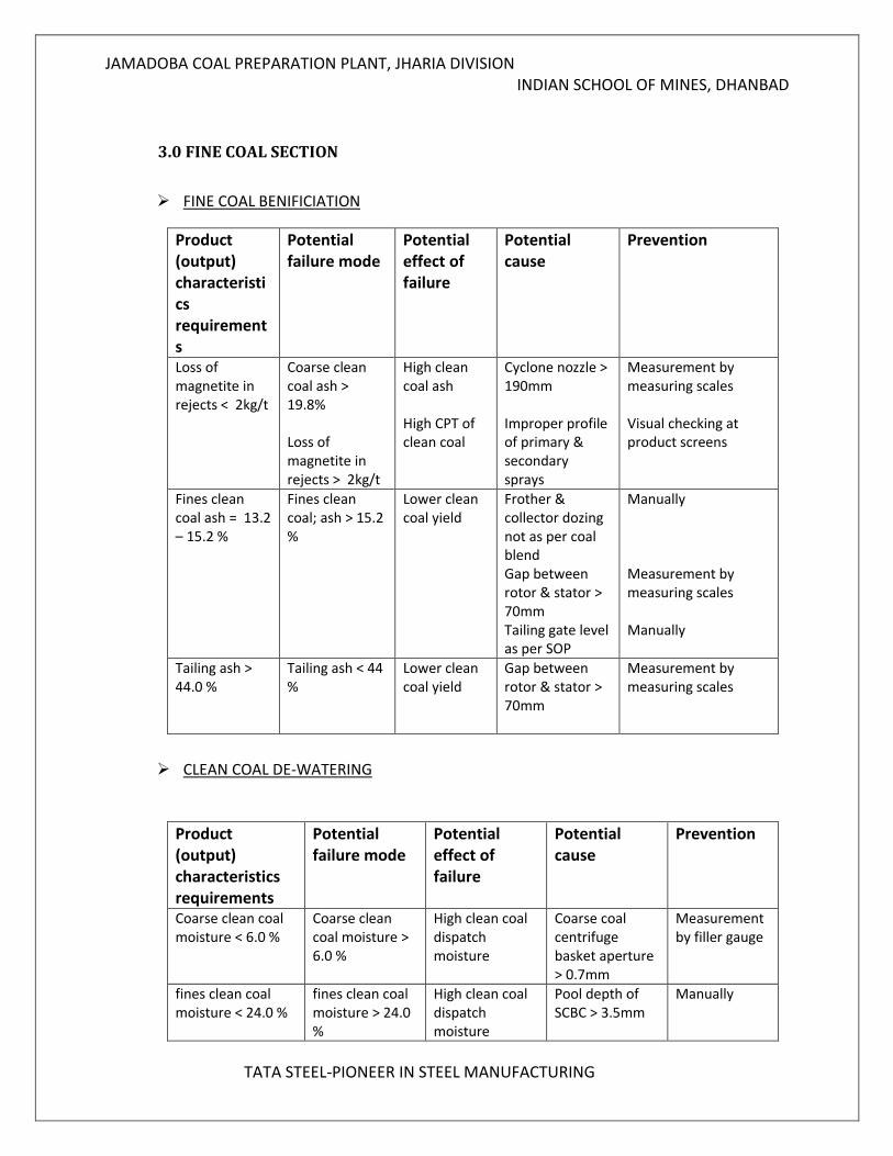
3.0 FINE COAL SECTION
FINE COAL BENIFICIATION
Product (output) characteristics requirements
Potential failure mode
Potential effect of failure
Potential cause
Prevention
Loss of magnetite in rejects < 2kg/t
Coarse clean coal ash > 19.8% Loss of magnetite in rejects > 2kg/t
High clean coal ash High CPT of clean coal
Cyclone nozzle > 190mm Improper profile of primary & secondary sprays
Measurement by measuring scales Visual checking at product screens
Fines clean coal ash = 13.2 – 15.2 %
Fines clean coal; ash > 15.2 %
Lower clean coal yield
Frother & collector dozing not as per coal blend Gap between rotor & stator > 70mm Tailing gate level as per SOP
Manually Measurement by measuring scales Manually
Tailing ash > 44.0 %
Tailing ash < 44 %
Lower clean coal yield
Gap between rotor & stator > 70mm
Measurement by measuring scales
CLEAN COAL DE-WATERING
Product (output) characteristics requirements
Potential failure mode
Potential effect of failure
Potential cause
Prevention
Coarse clean coal moisture < 6.0 %
Coarse clean coal moisture > 6.0 %
High clean coal dispatch moisture
Coarse coal centrifuge basket aperture > 0.7mm
Measurement by filler gauge
fines clean coal moisture < 24.0 %
fines clean coal moisture > 24.0 %
High clean coal dispatch moisture
Pool depth of SCBC > 3.5mm
Manually
JAMADOBA COAL PREPARATION PLANT, JHARIA DIVISION INDIAN SCHOOL OF MINES, DHANBAD
TATA STEEL-PIONEER IN STEEL MANUFACTURING
2.0 CHAPTER TWO- DENSE MEDIA CYCLONE
2.1 INTRODUCTION
Dense medium cyclones are the conical dynamic dense medium separators developed by Dutch State Mines in 1940s. These units are mainly used for coal cleaning applications. Geometrically DM cyclones are similar to hydrocyclone and generally use magnetite as a media to separate lights from heavies. DMC yclone operation is very simple and gained popularity many folds over conventional techniques for treating particularly intermediate size coal i.e. -50 +0.50mm. Due to the high tonnage, a small increase in DMC efficiency can have a large impact on plant profitability
At tata steel , Jamadoab or any other plant Dense media cyclone (DMC) treats 80% of the wahsery feed and hence feed rate of the washery can be increased when proper arrangement are made to increase the feed rate to DM cyclone.
80% of the feed is washed by DM cyclone (-15 +0.5 mm ) coal doesn’t responed well to gravity separation process due to the presence of high NGM in the coarse coal feed, hence the Ep (Ecart propabale) for the DM cyclone operation is also high.
In Jamadoba there are four DM cyclone named as DMC209-1 , DMC209-2, DMC209-3, DMC209-4.Earlier terminology was that two cyclone (DMC209-1, DMC209-2) were considered as FTS section and two( DMC209-3, DMC209-4) were considered as BF section.
There are four sieve bend named as CSS 211-1, CSS 211-2, CSS 211-3, CSS 211-4 used to recover the magnetic media from the cyclone product that ‘s clean coal , and there are two screen named as RS 215-1,RS 215-2 for Recovery of magnetic media from reject coal.
SOME ADVANTAGES OF DMC PROCESS OVER OTHER BENEFICIATION PROCESS
DMS have the ability to make sharp separations at any required relative density within the range normally required for coal preparation (and other minerals). A high degree of efficiency can be achieved even in the presence of high percentages of near density material (minerals/coal within ±0.1 relative density units of the cut point).
The rate of separation is much higher the any other bath, Fe> 500*g
The relative density and thereby the cut point, can be changed at will and fairly quickly to meet varying requirements.
A wide range of sizes (+0.1mm – 150mm) can be handled (each size range in different units), Through put capacity is much higher than any other bath
JAMADOBA COAL PREPARATION PLANT, JHARIA DIVISION INDIAN SCHOOL OF MINES, DHANBAD
TATA STEEL-PIONEER IN STEEL MANUFACTURING
WASHING OF COAL AT SIZE (-13 +.5 mm) IS MORE ECONOMICAL BECAUSE-
Lower capital and operating costs in size reduction
Dewatering is easy
Material handling and transportation at this size is very easy.
Lesser environmental problems for tailing disposal
2.2 DESIGN AND SEPARATION MECHANISM
The constructional features of a cyclone washers are essentially the same as that as a
cyclone thickener or cyclone classifier. The only difference lies in the mode of operation and
the use of medium for separation.
A cyclone washer consists of a cylindrical part with a tangential feed inlet and a cover plate
with a central outlet pipe at the top. A cone is fitted at the bottom of the cylinder having
suitable aperture at the apex. Over the cover plate there is a chamber with an outlet pipe.
In a typical dense media cyclone, the mixture of medium and raw coal enters tangentially
near the top of the cylindrical section, thus forming a strong vertical flow. The refuse moves
along th e wall of the cyclone and is discharged through the underflow orifice. The washed
coal moves towards the longitudinal axis of the cyclone and passes through the vortex
finder to the overflow chamber. The washed coal is discharged from this chamber, usually a
tangential outlet.
The lighter particles reverse its path and move towards the longitudinal axis of the cyclone
and pass through the vortex tinder as a clean coal.
In a cyclone washer, the force responsible for separation or sorting is the centrifugal which
is many times (50-100) greater than the gravitational force that effects separation of small
or fine particles in conventional washers including jigs and heavy medium units.
The effect of viscosity in the required separation of small or fines particles in the
conventional baths is eliminated to larger extent in cyclone washers. Thus the application of
centrifugal force in a cyclone washers makes it possible to efficiently treat coal down to a
bottom size of 0.5mm.
JAMADOBA COAL PREPARATION PLANT, JHARIA DIVISION INDIAN SCHOOL OF MINES, DHANBAD
TATA STEEL-PIONEER IN STEEL MANUFACTURING
OPERATING PRINCIPLE AND RESPONSIBLE FORCES
The buoyant forces acting on the coal particles cause them to rise the surface, the impurity
particles, being heavier than the liquid they displace, sink to the bottom.
The magnitude of the gravitational and buoyant forces that separate the particles is a
primary consideration because it governs the velocity with which the particles separate,
which in turn determines the capacity of the separating vessel.
In a static baths the net forces is written as Fg = (Mp-Mt)g
Where Fg= gravitational force, Mp= mass of particle,Mt= mass of fluid displaced by particle,
and g= acceleration of gravity
For float particels Fg will have a negative value
For sink particles Fg will have a positive value
In a cyclone specific gravity separation results primarily from application and utilization of
similar forces. However, the acceleration of gravity is substituted by a centrifugal
acceleration. Thus the equation changes to
Fc=(Mp – Mt)V2/R
Where Fc=centrifugal , V= tangential velocity and R= radius of cyclone
In a typical cyclone the centrifugal force acting on a particle in the inlet region is about 20
times greater than the gravitational force in a static bath , In the conical section of the
cyclone, V is further increased according to the relationship Vr1/2=constant
At the apex of the cyclone the acceleration increases to over 200 times greater than gravity.
Thus the forces tending to separate the coal and impurity particles are much greater in
cyclone than in other baths
GENERAL FLOW PATTERN OF THE MEDIUM IN A CYCLONE
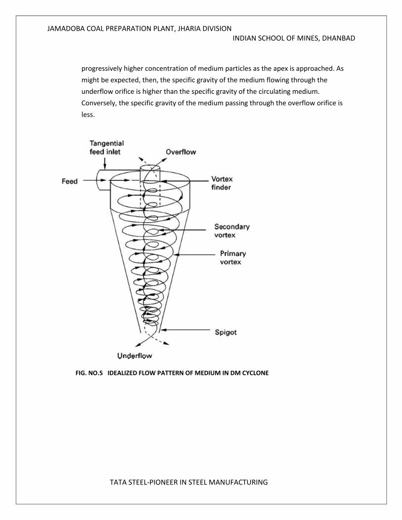
It consist of a descending vortex that originates at the inlet and progresses through the
cyclone to the underflow outlet. As the descending vortex passes down the cyclone, the
part of the fluid peels off toward the center of the cyclone to form an ascending vortex.
The ascending vortex, in turn surrounds a cylindrical air core that encircles the entire
longitudinal axis of the cyclone.
An additional factor that influence the separation is the progressive increase in specific
gravity of the medium as it descend towards the apex. This increase occurs because of
the centrifugal force also tend to force the medium particles toward the cyclone wall.
Therefore, they are preferentially caught in the descending vortex resulting in
JAMADOBA COAL PREPARATION PLANT, JHARIA DIVISION INDIAN SCHOOL OF MINES, DHANBAD
TATA STEEL-PIONEER IN STEEL MANUFACTURING
progressively higher concentration of medium particles as the apex is approached. As
might be expected, then, the specific gravity of the medium flowing through the
underflow orifice is higher than the specific gravity of the circulating medium.
Conversely, the specific gravity of the medium passing through the overflow orifice is
less.
FIG. NO.5 IDEALIZED FLOW PATTERN OF MEDIUM IN DM CYCLONE
JAMADOBA COAL PREPARATION PLANT, JHARIA DIVISION INDIAN SCHOOL OF MINES, DHANBAD
TATA STEEL-PIONEER IN STEEL MANUFACTURING
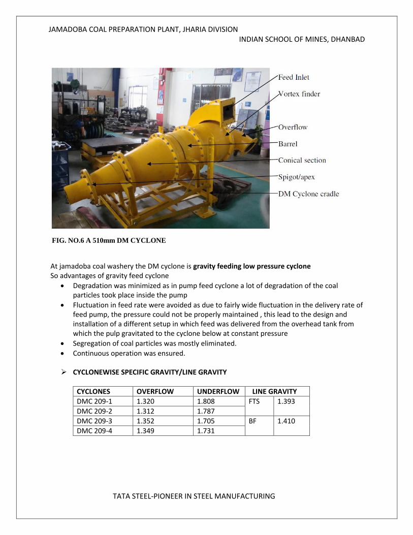
FIG. NO.6 A 510mm DM CYCLONE
At jamadoba coal washery the DM cyclone is gravity feeding low pressure cyclone So advantages of gravity feed cyclone
Degradation was minimized as in pump feed cyclone a lot of degradation of the coal particles took place inside the pump
Fluctuation in feed rate were avoided as due to fairly wide fluctuation in the delivery rate of feed pump, the pressure could not be properly maintained , this lead to the design and installation of a different setup in which feed was delivered from the overhead tank from which the pulp gravitated to the cyclone below at constant pressure
Segregation of coal particles was mostly eliminated.
Continuous operation was ensured.
CYCLONEWISE SPECIFIC GRAVITY/LINE GRAVITY
CYCLONES OVERFLOW UNDERFLOW LINE GRAVITY
DMC 209-1 1.320 1.808 FTS 1.393
DMC 209-2 1.312 1.787
DMC 209-3 1.352 1.705 BF 1.410
DMC 209-4 1.349 1.731
JAMADOBA COAL PREPARATION PLANT, JHARIA DIVISION INDIAN SCHOOL OF MINES, DHANBAD
TATA STEEL-PIONEER IN STEEL MANUFACTURING
2.3 COMMON PROBLEM IN DMC Field studies indicate that the most common troubles encountered in dense
Medium cyclone circuits include:
Clean coal vortex overload, Excessive particle retention, Improper specific gravity cut-point
1. CLEAN COAL VORTEX OVERLOAD
The vortex finder of a dense medium cyclone is somewhat analogous to the overflow lip of a dense medium vessel. In a vessel, a minimum depth of overflow of 7-10cm must be maintained to ensure that the largest size particles of clean coal can be hydraulically carried into the clean product. Likewise, an adequate flow of medium containing the proper amount of medium particles must pass through the vortex finder of a DMC in order to carry out the coal particles. If the flow of medium to the overflow is too low, then the excess clean coal cannot be carried through the vortex finder and will instead report to refuse. This problem is common in DMCs operated with too large an apex or too low of an inlet pressure.
2. EXCESSIVE PARTICLE RETENTION
The centrifugal field within a DMC causes magnetite to classify and preferentially report to underflow. The classification causes the underflow SG to be higher than that of the feed and the overflow SG to be lower than that of the feed. As a result, middlings particles that have a density between that of the feed SG and overflow SG tend to remain in the cyclone for a longer period of time than particles outside this density range. Retention is normally associated with only the coarsest particles and rarely occurs for particles finer than about 15 mm. The retention of coarser middlings may even improve the separation by breaking middlings into smaller particles that are better liberated and easier to discharge. However, particle retention can be a serious problem when middlings particles enter the cyclone at a faster rate than they can be removed. The excessive build-up of middlings eventually leads to a sudden surge to the underflow that clears the accumulated load of retained material. Unfortunately, the surge also tends to carry out a portion of low-density clean coal to the refuse stream.
3. IMPROPER SPECIFIC GRAVITY CUT-POINT
Dense medium cyclones are frequently installed in banks of two or more parallel units in order to achieve the production requirements of a given plant. For all practical purposes, the maximum yield from such a circuit can only be achieved when all of the DMCs are operated at the same specific gravity cut-points. This optimization principle is valid regardless of the desired quality of the total clean coal product or the ratios of different coals passed through the circuit.
JAMADOBA COAL PREPARATION PLANT, JHARIA DIVISION INDIAN SCHOOL OF MINES, DHANBAD
TATA STEEL-PIONEER IN STEEL MANUFACTURING
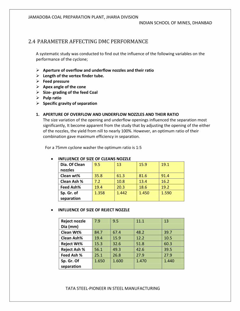
2.4 PARAMETER AFFECTING DMC PERFORMANCE A systematic study was conducted to find out the influence of the following variables on the performance of the cyclone; Aperture of overflow and underflow nozzles and their ratio Length of the vertex finder tube. Feed pressure Apex angle of the cone Size- grading of the feed Coal Pulp ratio Specific gravity of separation 1. APERTURE OF OVERFLOW AND UNDERFLOW NOZZLES AND THEIR RATIO
The size variation of the opening and underflow openings influenced the separation most significantly, It become apparent from the study that by adjusting the opening of the either of the nozzles, the yield from nill to nearly 100%. However, an optimum ratio of their combination gave maximum efficiency in separation. For a 75mm cyclone washer the optimum ratio is 1:5
INFLUENCE OF SIZE OF CLEANS NOZZLE
Dia. Of Clean nozzles
9.5 13 15.9 19.1
Clean wt% 35.8 61.3 81.6 91.4
Clean Ash % 7.2 10.8 13.4 16.2
Feed Ash% 19.4 20.3 18.6 19.2
Sp. Gr. of separation
1.358 1.442 1.450 1.590
INFLUENCE OF SIZE OF REJECT NOZZLE
Reject nozzle Dia (mm)
7.9 9.5 11.1 13
Clean Wt% 84.7 67.4 48.2 39.7
Clean Ash% 19.4 15.9 12.2 10.5
Reject Wt% 15.3 32.6 51.8 60.3
Reject Ash % 56.1 49.3 42.6 39.5
Feed Ash % 25.1 26.8 27.9 27.9
Sp. Gr. Of separation
1.650 1.600 1.470 1.440
JAMADOBA COAL PREPARATION PLANT, JHARIA DIVISION INDIAN SCHOOL OF MINES, DHANBAD
TATA STEEL-PIONEER IN STEEL MANUFACTURING
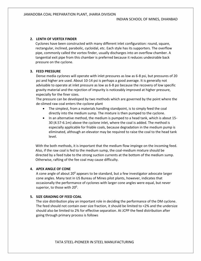
2. LENTH OF VERTEX FINDER
Cyclones have been constructed with many different inlet configuration: round, square, rectangular, inclined, parabolic, cycloidal, etc. Each style has its supporters. The overflow pipe, commonly called the vortex finder, usually discharges into an overflow chamber. A tangential exit pipe from this chamber is preferred because it reduces undesirable back pressure on the cyclone.
3. FEED PRESSURE
Dense media cyclones will operate with inlet pressures as low as 6-8 psi, but pressures of 20 psi and higher are used. About 10-14 psi is perhaps a good average. It is generally not advisable to operate at inlet pressure as low as 6-8 psi because the recovery of low specific gravity material and the rejection of impurity is noticeably improved at higher pressure, especially for the finer sizes. The pressure can be developed by two methods which are governed by the point where the de-slimed raw coal enters the cyclone plant
The simplest, from a materials handling standpoint, is to simply feed the coal directly into the medium sump. The mixture is then pumped to the cyclone.
In an alternative method, the medium is pumped to a head tank, which is about 15-30 (4.57-6.1m) above the cyclone inlet, where the coal is added. The method is especially applicable for friable coals, because degradation in the medium pump is eliminated, although an elevator may be required to raise the coal to the head tank level.
With the both methods, it is important that the medium flow impinge on the incoming feed. Also, if the raw coal is fed to the medium sump, the coal-medium mixture should be directed by a feed tube to the strong suction currents at the bottom of the medium sump. Otherwise, rafting of the fee coal may cause difficulty.
4. APEX ANGLE OF CONE A cone angle of about 200 appears to be standard, but a few investigator advocate larger cone angles. Many test in US Bureau of Mines pilot plants, however, indicates that occasionally the performance of cyclones with larger cone angles were equal, but never superior, to those with 200.
5. SIZE GRADING OF FEED COAL The size distribution play an important role in deciding the performance of the DM cyclone. The feed should not contain over size fraction, it should be limited to <2% and the undersize should also be limited to 2% for effective separation. At JCPP the feed distribution after going through primary process is follows
JAMADOBA COAL PREPARATION PLANT, JHARIA DIVISION INDIAN SCHOOL OF MINES, DHANBAD
TATA STEEL-PIONEER IN STEEL MANUFACTURING
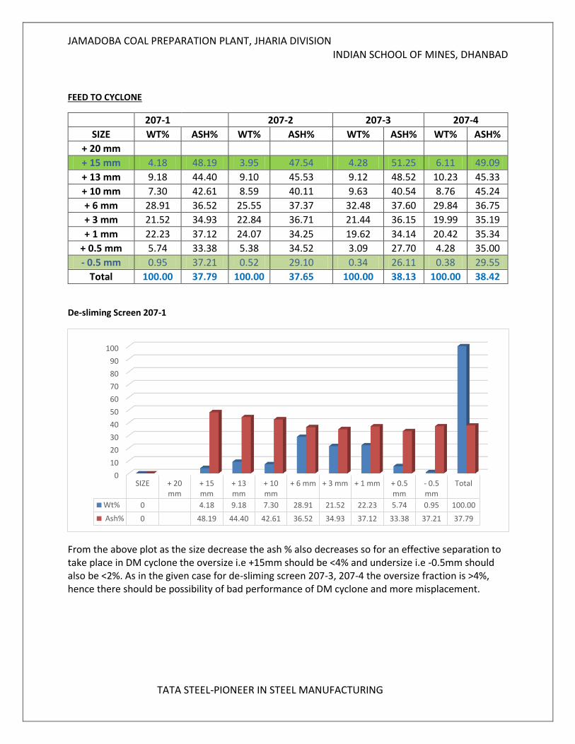
FEED TO CYCLONE
De-sliming Screen 207-1
From the above plot as the size decrease the ash % also decreases so for an effective separation to take place in DM cyclone the oversize i.e +15mm should be <4% and undersize i.e -0.5mm should also be <2%. As in the given case for de-sliming screen 207-3, 207-4 the oversize fraction is >4%, hence there should be possibility of bad performance of DM cyclone and more misplacement.
0
10
20
30
40
50
60
70
80
90
100
SIZE + 20mm
+ 15mm
+ 13mm
+ 10mm
+ 6 mm + 3 mm + 1 mm + 0.5mm
- 0.5mm
Total
Wt% 0 4.18 9.18 7.30 28.91 21.52 22.23 5.74 0.95 100.00
Ash% 0 48.19 44.40 42.61 36.52 34.93 37.12 33.38 37.21 37.79
207-1 207-2 207-3 207-4
SIZE WT% ASH% WT% ASH% WT% ASH% WT% ASH%
+ 20 mm
+ 15 mm 4.18 48.19 3.95 47.54 4.28 51.25 6.11 49.09
+ 13 mm 9.18 44.40 9.10 45.53 9.12 48.52 10.23 45.33
+ 10 mm 7.30 42.61 8.59 40.11 9.63 40.54 8.76 45.24
+ 6 mm 28.91 36.52 25.55 37.37 32.48 37.60 29.84 36.75
+ 3 mm 21.52 34.93 22.84 36.71 21.44 36.15 19.99 35.19
+ 1 mm 22.23 37.12 24.07 34.25 19.62 34.14 20.42 35.34
+ 0.5 mm 5.74 33.38 5.38 34.52 3.09 27.70 4.28 35.00
- 0.5 mm 0.95 37.21 0.52 29.10 0.34 26.11 0.38 29.55
Total 100.00 37.79 100.00 37.65 100.00 38.13 100.00 38.42
JAMADOBA COAL PREPARATION PLANT, JHARIA DIVISION INDIAN SCHOOL OF MINES, DHANBAD
TATA STEEL-PIONEER IN STEEL MANUFACTURING
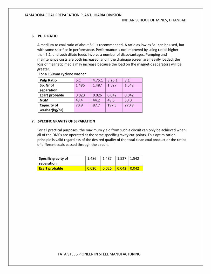
6. PULP RATIO
A medium to coal ratio of about 5:1 is recommended. A ratio as low as 3:1 can be used, but with some sacrifice in performance. Performance is not improved by using ratios higher than 5:1, and such dilute feeds involve a number of disadvantages. Pumping and maintenance costs are both increased, and if the drainage screen are heavily loaded, the loss of magnetic media may increase because the load on the magnetic separators will be greater. For a 150mm cyclone washer
Pulp Ratio 6:1 4.75:1 3.25:1 3:1
Sp. Gr of separation
1.486 1.487 1.527 1.542
Ecart probable 0.020 0.026 0.042 0.042
NGM 43.4 44.2 48.5 50.0
Capacity of washer(kg/hr)
70.9 87.7 197.3 270.9
7. SPECIFIC GRAVITY OF SEPARATION
For all practical purposes, the maximum yield from such a circuit can only be achieved when all of the DMCs are operated at the same specific gravity cut-points. This optimization principle is valid regardless of the desired quality of the total clean coal product or the ratios of different coals passed through the circuit.
Specific gravity of separation
1.486 1.487 1.527 1.542
Ecart probable 0.020 0.026 0.042 0.042
JAMADOBA COAL PREPARATION PLANT, JHARIA DIVISION INDIAN SCHOOL OF MINES, DHANBAD
TATA STEEL-PIONEER IN STEEL MANUFACTURING
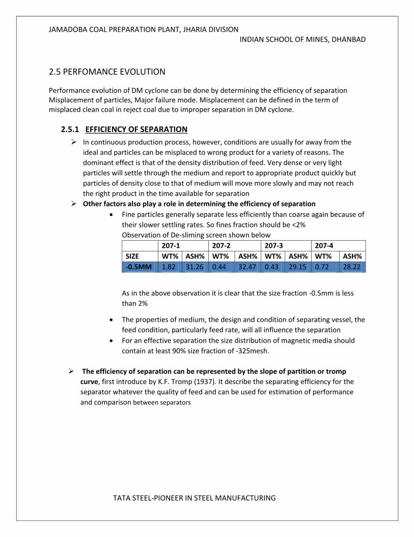
2.5 PERFOMANCE EVOLUTION
Performance evolution of DM cyclone can be done by determining the efficiency of separation Misplacement of particles, Major failure mode. Misplacement can be defined in the term of misplaced clean coal in reject coal due to improper separation in DM cyclone.
2.5.1 EFFICIENCY OF SEPARATION
In continuous production process, however, conditions are usually for away from the
ideal and particles can be misplaced to wrong product for a variety of reasons. The
dominant effect is that of the density distribution of feed. Very dense or very light
particles will settle through the medium and report to appropriate product quickly but
particles of density close to that of medium will move more slowly and may not reach
the right product in the time available for separation
Other factors also play a role in determining the efficiency of separation
Fine particles generally separate less efficiently than coarse again because of
their slower settling rates. So fines fraction should be <2%
Observation of De-sliming screen shown below
207-1 207-2 207-3 207-4
SIZE WT% ASH% WT% ASH% WT% ASH% WT% ASH%
-0.5MM 1.82 31.26 0.44 32.47 0.43 29.15 0.72 28.22
As in the above observation it is clear that the size fraction -0.5mm is less
than 2%
The properties of medium, the design and condition of separating vessel, the
feed condition, particularly feed rate, will all influence the separation
For an effective separation the size distribution of magnetic media should
contain at least 90% size fraction of -325mesh.
The efficiency of separation can be represented by the slope of partition or tromp
curve, first introduce by K.F. Tromp (1937). It describe the separating efficiency for the
separator whatever the quality of feed and can be used for estimation of performance
and comparison between separators
JAMADOBA COAL PREPARATION PLANT, JHARIA DIVISION INDIAN SCHOOL OF MINES, DHANBAD
TATA STEEL-PIONEER IN STEEL MANUFACTURING
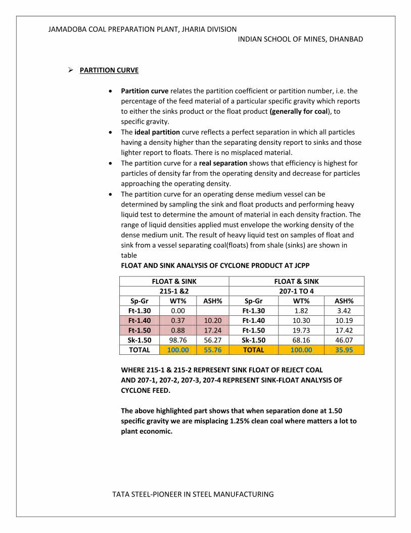
PARTITION CURVE
Partition curve relates the partition coefficient or partition number, i.e. the
percentage of the feed material of a particular specific gravity which reports
to either the sinks product or the float product (generally for coal), to
specific gravity.
The ideal partition curve reflects a perfect separation in which all particles
having a density higher than the separating density report to sinks and those
lighter report to floats. There is no misplaced material.
The partition curve for a real separation shows that efficiency is highest for
particles of density far from the operating density and decrease for particles
approaching the operating density.
The partition curve for an operating dense medium vessel can be
determined by sampling the sink and float products and performing heavy
liquid test to determine the amount of material in each density fraction. The
range of liquid densities applied must envelope the working density of the
dense medium unit. The result of heavy liquid test on samples of float and
sink from a vessel separating coal(floats) from shale (sinks) are shown in
table
FLOAT AND SINK ANALYSIS OF CYCLONE PRODUCT AT JCPP
FLOAT & SINK FLOAT & SINK
215-1 &2 207-1 TO 4
Sp-Gr WT% ASH% Sp-Gr WT% ASH%
Ft-1.30 0.00 Ft-1.30 1.82 3.42
Ft-1.40 0.37 10.20 Ft-1.40 10.30 10.19
Ft-1.50 0.88 17.24 Ft-1.50 19.73 17.42
Sk-1.50 98.76 56.27 Sk-1.50 68.16 46.07
TOTAL 100.00 55.76 TOTAL 100.00 35.95
WHERE 215-1 & 215-2 REPRESENT SINK FLOAT OF REJECT COAL
AND 207-1, 207-2, 207-3, 207-4 REPRESENT SINK-FLOAT ANALYSIS OF
CYCLONE FEED.
The above highlighted part shows that when separation done at 1.50
specific gravity we are misplacing 1.25% clean coal where matters a lot to
plant economic.
JAMADOBA COAL PREPARATION PLANT, JHARIA DIVISION INDIAN SCHOOL OF MINES, DHANBAD
TATA STEEL-PIONEER IN STEEL MANUFACTURING
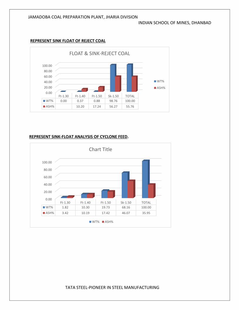
REPRESENT SINK FLOAT OF REJECT COAL
REPRESENT SINK-FLOAT ANALYSIS OF CYCLONE FEED.
0.00
20.00
40.00
60.00
80.00
100.00
Ft-1.30 Ft-1.40 Ft-1.50 Sk-1.50 TOTAL
WT% 0.00 0.37 0.88 98.76 100.00
ASH% 10.20 17.24 56.27 55.76
FLOAT & SINK-REJECT COAL
WT%
ASH%
0.00
20.00
40.00
60.00
80.00
100.00
Ft-1.30 Ft-1.40 Ft-1.50 Sk-1.50 TOTAL
WT% 1.82 10.30 19.73 68.16 100.00
ASH% 3.42 10.19 17.42 46.07 35.95
Chart Title
WT% ASH%
JAMADOBA COAL PREPARATION PLANT, JHARIA DIVISION INDIAN SCHOOL OF MINES, DHANBAD
TATA STEEL-PIONEER IN STEEL MANUFACTURING
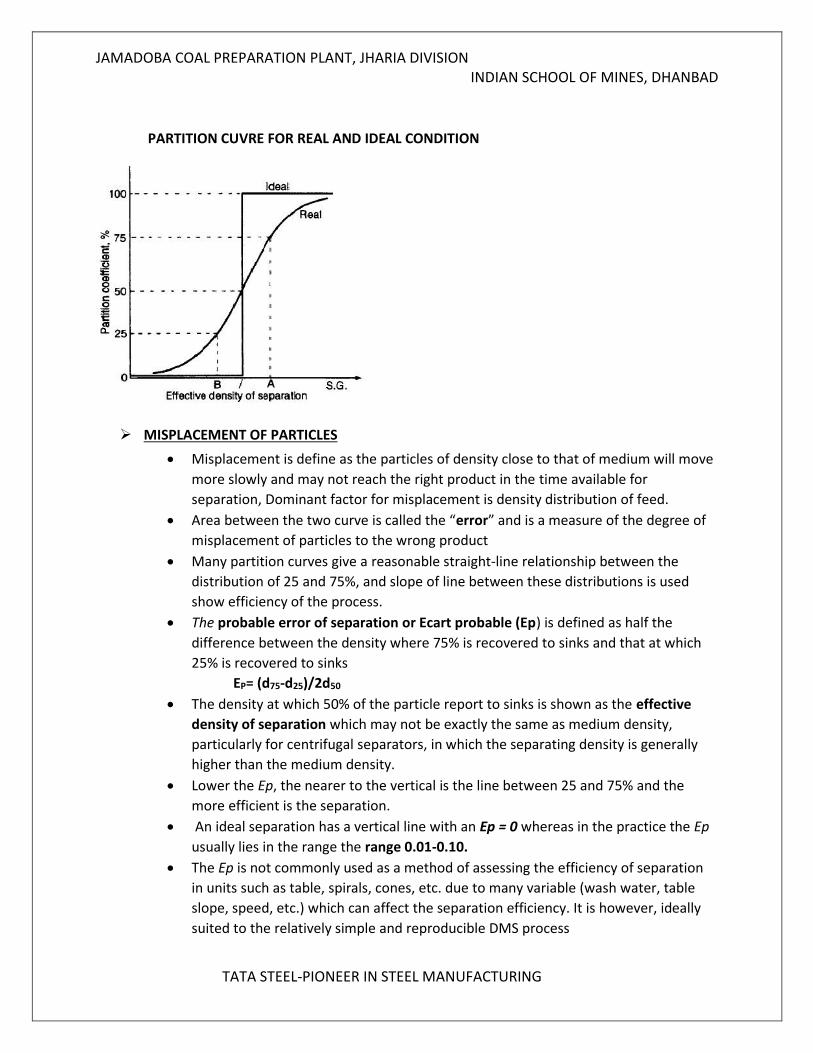
PARTITION CUVRE FOR REAL AND IDEAL CONDITION
MISPLACEMENT OF PARTICLES
Misplacement is define as the particles of density close to that of medium will move
more slowly and may not reach the right product in the time available for
separation, Dominant factor for misplacement is density distribution of feed.
Area between the two curve is called the “error” and is a measure of the degree of
misplacement of particles to the wrong product
Many partition curves give a reasonable straight-line relationship between the
distribution of 25 and 75%, and slope of line between these distributions is used
show efficiency of the process.
The probable error of separation or Ecart probable (Ep) is defined as half the
difference between the density where 75% is recovered to sinks and that at which
25% is recovered to sinks
EP= (d75-d25)/2d50
The density at which 50% of the particle report to sinks is shown as the effective
density of separation which may not be exactly the same as medium density,
particularly for centrifugal separators, in which the separating density is generally
higher than the medium density.
Lower the Ep, the nearer to the vertical is the line between 25 and 75% and the
more efficient is the separation.
An ideal separation has a vertical line with an Ep = 0 whereas in the practice the Ep
usually lies in the range the range 0.01-0.10.
The Ep is not commonly used as a method of assessing the efficiency of separation
in units such as table, spirals, cones, etc. due to many variable (wash water, table
slope, speed, etc.) which can affect the separation efficiency. It is however, ideally
suited to the relatively simple and reproducible DMS process
JAMADOBA COAL PREPARATION PLANT, JHARIA DIVISION INDIAN SCHOOL OF MINES, DHANBAD
TATA STEEL-PIONEER IN STEEL MANUFACTURING
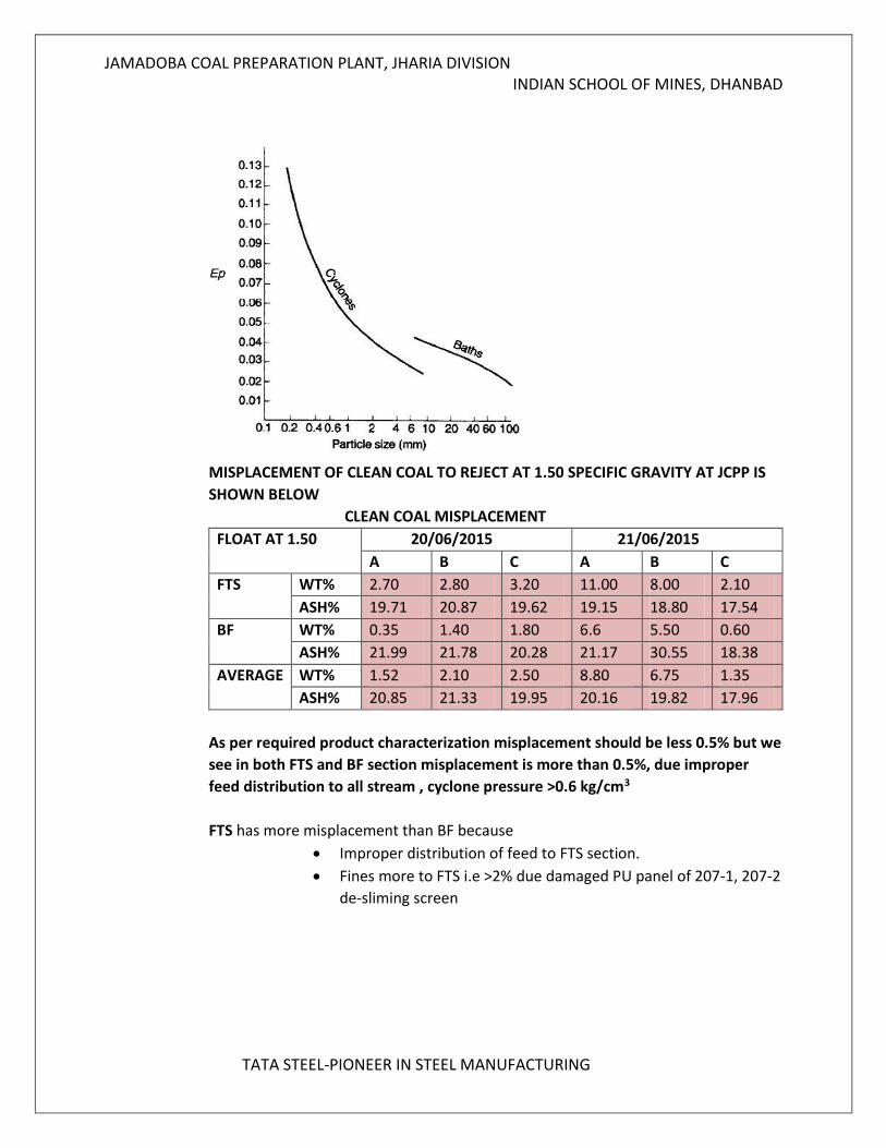
MISPLACEMENT OF CLEAN COAL TO REJECT AT 1.50 SPECIFIC GRAVITY AT JCPP IS
SHOWN BELOW
CLEAN COAL MISPLACEMENT
FLOAT AT 1.50 20/06/2015 21/06/2015
A B C A B C
FTS WT% 2.70 2.80 3.20 11.00 8.00 2.10
ASH% 19.71 20.87 19.62 19.15 18.80 17.54
BF WT% 0.35 1.40 1.80 6.6 5.50 0.60
ASH% 21.99 21.78 20.28 21.17 30.55 18.38
AVERAGE WT% 1.52 2.10 2.50 8.80 6.75 1.35
ASH% 20.85 21.33 19.95 20.16 19.82 17.96
As per required product characterization misplacement should be less 0.5% but we
see in both FTS and BF section misplacement is more than 0.5%, due improper
feed distribution to all stream , cyclone pressure >0.6 kg/cm3
FTS has more misplacement than BF because
Improper distribution of feed to FTS section.
Fines more to FTS i.e >2% due damaged PU panel of 207-1, 207-2
de-sliming screen
JAMADOBA COAL PREPARATION PLANT, JHARIA DIVISION INDIAN SCHOOL OF MINES, DHANBAD
TATA STEEL-PIONEER IN STEEL MANUFACTURING
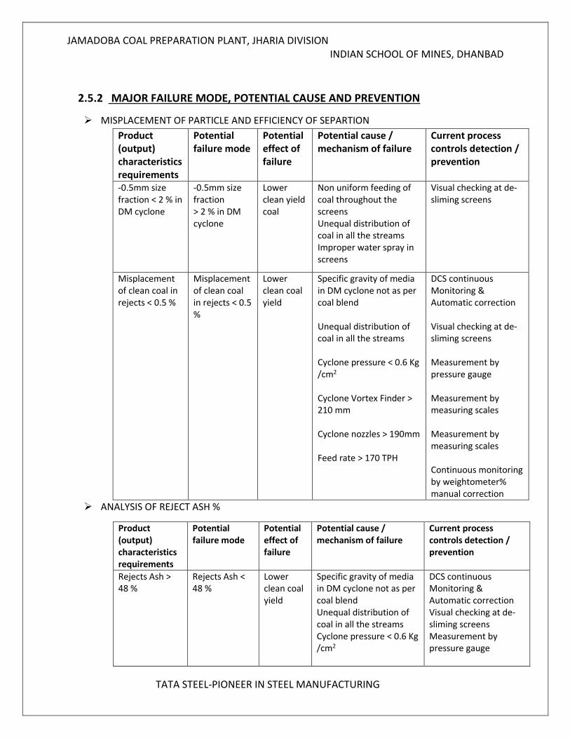
2.5.2 MAJOR FAILURE MODE, POTENTIAL CAUSE AND PREVENTION
MISPLACEMENT OF PARTICLE AND EFFICIENCY OF SEPARTION
ANALYSIS OF REJECT ASH %
Product (output) characteristics requirements
Potential failure mode
Potential effect of failure
Potential cause / mechanism of failure
Current process controls detection / prevention
Rejects Ash > 48 %
Rejects Ash < 48 %
Lower clean coal yield
Specific gravity of media in DM cyclone not as per coal blend Unequal distribution of coal in all the streams Cyclone pressure < 0.6 Kg /cm2
DCS continuous Monitoring & Automatic correction Visual checking at de-sliming screens Measurement by pressure gauge
Product (output) characteristics requirements
Potential failure mode
Potential effect of failure
Potential cause / mechanism of failure
Current process controls detection / prevention
-0.5mm size fraction < 2 % in DM cyclone
-0.5mm size fraction > 2 % in DM cyclone
Lower clean yield coal
Non uniform feeding of coal throughout the screens Unequal distribution of coal in all the streams Improper water spray in screens
Visual checking at de-sliming screens
Misplacement of clean coal in rejects < 0.5 %
Misplacement of clean coal in rejects < 0.5 %
Lower clean coal yield
Specific gravity of media in DM cyclone not as per coal blend Unequal distribution of coal in all the streams Cyclone pressure < 0.6 Kg /cm2 Cyclone Vortex Finder > 210 mm Cyclone nozzles > 190mm Feed rate > 170 TPH
DCS continuous Monitoring & Automatic correction Visual checking at de-sliming screens Measurement by pressure gauge Measurement by measuring scales Measurement by measuring scales Continuous monitoring by weightometer% manual correction
JAMADOBA COAL PREPARATION PLANT, JHARIA DIVISION INDIAN SCHOOL OF MINES, DHANBAD
TATA STEEL-PIONEER IN STEEL MANUFACTURING
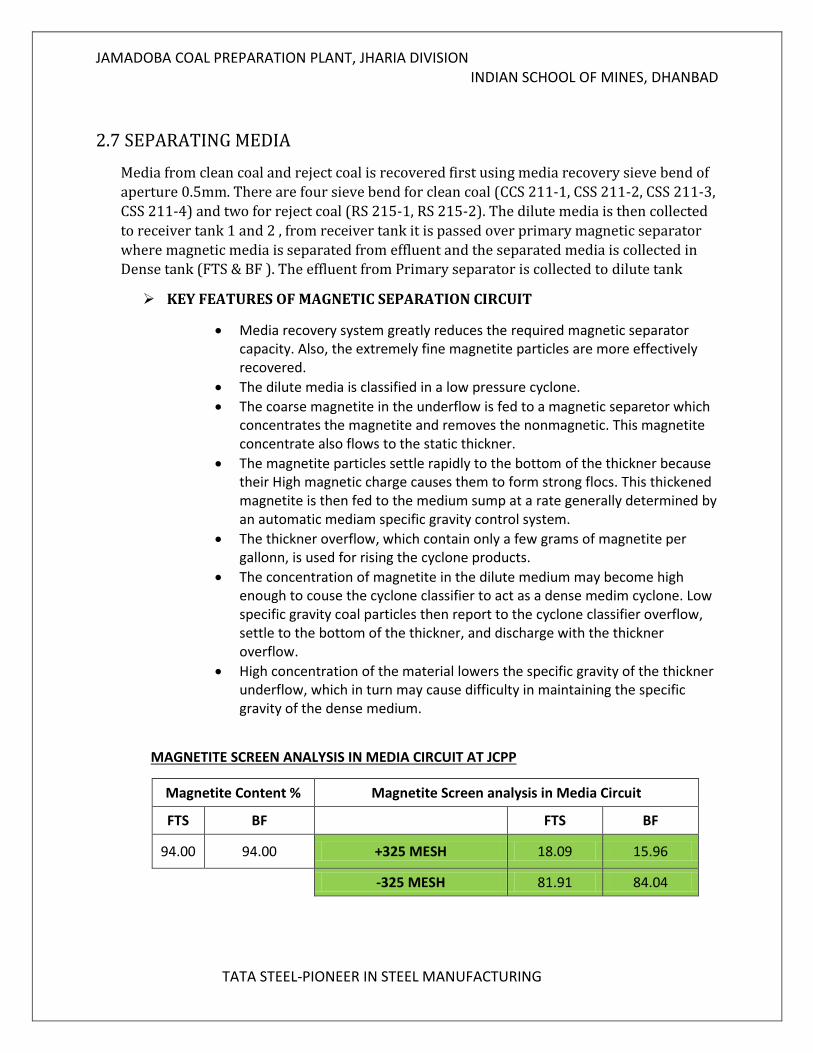
2.7 SEPARATING MEDIA
Media from clean coal and reject coal is recovered first using media recovery sieve bend of
aperture 0.5mm. There are four sieve bend for clean coal (CCS 211-1, CSS 211-2, CSS 211-3,
CSS 211-4) and two for reject coal (RS 215-1, RS 215-2). The dilute media is then collected
to receiver tank 1 and 2 , from receiver tank it is passed over primary magnetic separator
where magnetic media is separated from effluent and the separated media is collected in Dense tank (FTS & BF ). The effluent from Primary separator is collected to dilute tank
KEY FEATURES OF MAGNETIC SEPARATION CIRCUIT
Media recovery system greatly reduces the required magnetic separator capacity. Also, the extremely fine magnetite particles are more effectively recovered.
The dilute media is classified in a low pressure cyclone.
The coarse magnetite in the underflow is fed to a magnetic separetor which concentrates the magnetite and removes the nonmagnetic. This magnetite concentrate also flows to the static thickner.
The magnetite particles settle rapidly to the bottom of the thickner because their High magnetic charge causes them to form strong flocs. This thickened magnetite is then fed to the medium sump at a rate generally determined by an automatic mediam specific gravity control system.
The thickner overflow, which contain only a few grams of magnetite per gallonn, is used for rising the cyclone products.
The concentration of magnetite in the dilute medium may become high enough to couse the cyclone classifier to act as a dense medim cyclone. Low specific gravity coal particles then report to the cyclone classifier overflow, settle to the bottom of the thickner, and discharge with the thickner overflow.
High concentration of the material lowers the specific gravity of the thickner underflow, which in turn may cause difficulty in maintaining the specific gravity of the dense medium.
MAGNETITE SCREEN ANALYSIS IN MEDIA CIRCUIT AT JCPP
Magnetite Content % Magnetite Screen analysis in Media Circuit
FTS BF FTS BF
94.00 94.00 +325 MESH 18.09 15.96
-325 MESH 81.91 84.04
JAMADOBA COAL PREPARATION PLANT, JHARIA DIVISION INDIAN SCHOOL OF MINES, DHANBAD
TATA STEEL-PIONEER IN STEEL MANUFACTURING
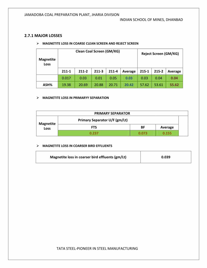
2.7.1 MAJOR LOSSES
MAGNETITE LOSS IN COARSE CLEAN SCREEN AND REJECT SCREEN
Magnetite Loss
Clean Coal Screen (GM/KG)
Reject Screen (GM/KG)
211-1 211-2 211-3 211-4 Average 215-1 215-2 Average
0.017 0.03 0.01 0.05 0.03 0.03 0.04 0.04
ASH% 19.38 20.69 20.88 20.71 20.42 57.62 53.61 55.62
MAGNETITE LOSS IN PRIMARYY SEPARATION
PRIMARY SEPARATOR
Magnetite Loss
Primary Separator U/F (gm/Lt)
FTS BF Average 0.237 0.073 0.155
MAGNETITE LOSS IN COARSER BIRD EFFLUENTS
Magnetite loss in coarser bird effluents (gm/Lt) 0.039
JAMADOBA COAL PREPARATION PLANT, JHARIA DIVISION INDIAN SCHOOL OF MINES, DHANBAD
TATA STEEL-PIONEER IN STEEL MANUFACTURING
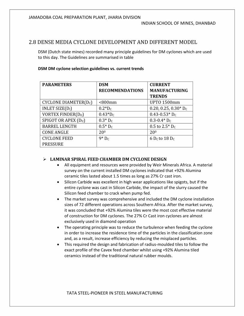
2.8 DENSE MEDIA CYCLONE DEVELOPMENT AND DIFFERENT MODEL
DSM (Dutch state mines) recorded many principle guidelines for DM cyclones which are used to this day. The Guidelines are summarised in table DSM DM cyclone selection guidelines vs. current trends
PARAMETERS DSM
RECOMMENDATIONS
CURRENT
MANUFACTURING
TRENDS
CYCLONE DIAMETER(DC) <800mm UPTO 1500mm
INLET SIZE(DI) 0.2*DC 0.20, 0.25, 0.30* DC
VORTEX FINDER(DO) 0.43*DC 0.43-0.53* DC
SPIGOT OR APEX (DU) 0.3* DC 0.3-0.4* DC
BARREL LENGTH 0.5* DC 0.5 to 2.5* DC
CONE ANGLE 200 200
CYCLONE FEED
PRESSURE
9* DC 6 DC to 18 DC
LAMINAR SPIRAL FEED CHAMBER DM CYCLONE DESIGN All equipment and resources were provided by Weir Minerals Africa. A material
survey on the current installed DM cyclones indicated that +92% Alumina ceramic tiles lasted about 1.5 times as long as 27% Cr cast iron.
Silicon Carbide was excellent in high wear applications like spigots, but if the entire cyclone was cast in Silicon Carbide, the impact of the slurry caused the Silicon feed chamber to crack when pump fed.
The market survey was comprehensive and included the DM cyclone installation sizes of 72 different operations across Southern Africa. After the market survey, it was concluded that +92% Alumina tiles were the most cost effective material of construction for DM cyclones. The 27% Cr Cast iron cyclones are almost exclusively used in diamond operation
The operating principle was to reduce the turbulence when feeding the cyclone in order to increase the residence time of the particles in the classification zone and, as a result, increase efficiency by reducing the misplaced particles.
This required the design and fabrication of radius-moulded tiles to follow the exact profile of the Cavex feed chamber whilst using +92% Alumina tiled
ceramics instead of the traditional natural rubber moulds.
JAMADOBA COAL PREPARATION PLANT, JHARIA DIVISION INDIAN SCHOOL OF MINES, DHANBAD
TATA STEEL-PIONEER IN STEEL MANUFACTURING
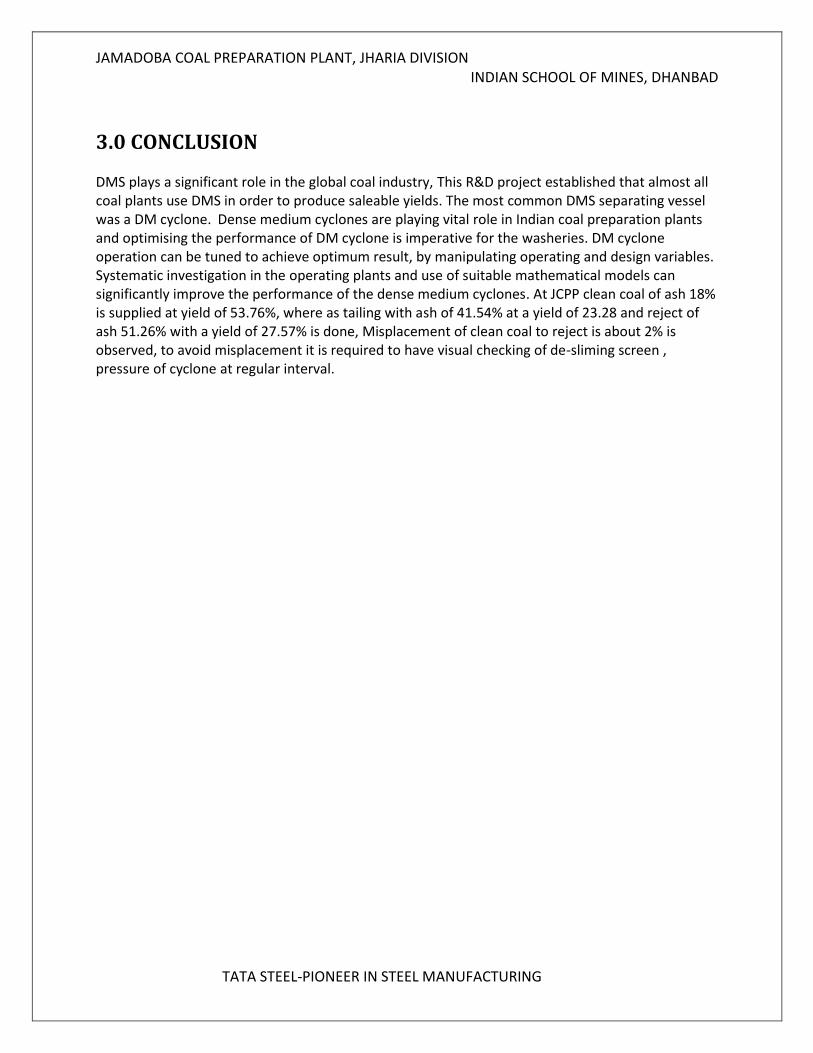
3.0 CONCLUSION DMS plays a significant role in the global coal industry, This R&D project established that almost all coal plants use DMS in order to produce saleable yields. The most common DMS separating vessel was a DM cyclone. Dense medium cyclones are playing vital role in Indian coal preparation plants and optimising the performance of DM cyclone is imperative for the washeries. DM cyclone operation can be tuned to achieve optimum result, by manipulating operating and design variables. Systematic investigation in the operating plants and use of suitable mathematical models can significantly improve the performance of the dense medium cyclones. At JCPP clean coal of ash 18% is supplied at yield of 53.76%, where as tailing with ash of 41.54% at a yield of 23.28 and reject of ash 51.26% with a yield of 27.57% is done, Misplacement of clean coal to reject is about 2% is observed, to avoid misplacement it is required to have visual checking of de-sliming screen , pressure of cyclone at regular interval.
JAMADOBA COAL PREPARATION PLANT, JHARIA DIVISION INDIAN SCHOOL OF MINES, DHANBAD
TATA STEEL-PIONEER IN STEEL MANUFACTURING
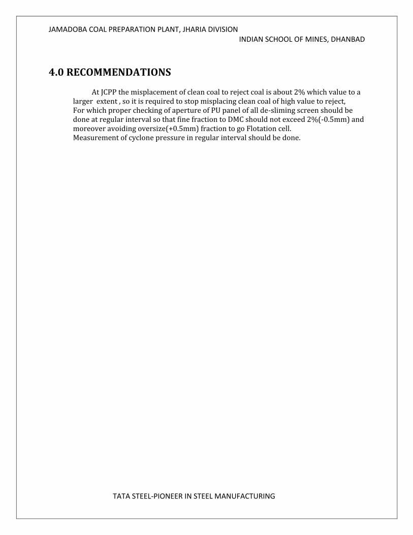
4.0 RECOMMENDATIONS
At JCPP the misplacement of clean coal to reject coal is about 2% which value to a larger extent , so it is required to stop misplacing clean coal of high value to reject, For which proper checking of aperture of PU panel of all de-sliming screen should be done at regular interval so that fine fraction to DMC should not exceed 2%(-0.5mm) and moreover avoiding oversize(+0.5mm) fraction to go Flotation cell. Measurement of cyclone pressure in regular interval should be done.
JAMADOBA COAL PREPARATION PLANT, JHARIA DIVISION INDIAN SCHOOL OF MINES, DHANBAD
TATA STEEL-PIONEER IN STEEL MANUFACTURING
5.0 REFERENCE
GEOLOGICAL SECTION OF JCPP STUDIES ON COAL PREPARATION IN INDIA(CFRI) COAL PREPARATION BY LEONARD DEVELOPMENT AND EVALUATION OF A DENSE MEDIA CYCLONE FOR THE SOUTHERN AFRICAN
MINERAL AND COAL INDUSTRIES https://www.google.co.in/ https://scholar.google.co.in/ WILL’S MINERAL PROCESSING TECHNOLOGY