Rahul Soni's Training Report
36
1 A REPORT ON PRACTICAL TRAINING TAKEN AT National Engineering Industries Ltd. (NEI), JAIPUR, RAJASTHAN. FROM: 01.06.2012 to 30.06.2012 IN THE PARTIAL FULFILLMENT FOR AWARD THE DEGREE OF Bachelor of Technology From Rajasthan Technical University Session 2012-2013 Submitted To: Submitted by: Rajesh Ranjan Sir , Rahul Soni Head of Department Mechanical Engineering, IIMET JAIPUR B.TECHIVYEAR, . VII SEM IIMET. Department of Mechanical Engineering International Institute of Management, Engg. & Tech. Sitapura Industrial Area, Tonk Road, Jaipur
-
Upload
sandeep-kumar-gupta -
Category
Documents
-
view
223 -
download
0
Transcript of Rahul Soni's Training Report

7/27/2019 Rahul Soni's Training Report
http://slidepdf.com/reader/full/rahul-sonis-training-report 1/36
1
A
REPORT ON
PRACTICAL TRAINING
TAKEN AT
National Engineering Industries Ltd. (NEI),
JAIPUR, RAJASTHAN.
FROM: 01.06.2012 to 30.06.2012
IN THE PARTIAL FULFILLMENT FOR AWARD THE DEGREE OF
Bachelor of Technology
From
Rajasthan Technical University
Session 2012-2013
Submitted To: Submitted by:
Rajesh Ranjan Sir , Rahul SoniHead of Department Mechanical Engineering,
IIMET JAIPUR B.TECHIVYEAR,
. VII SEM IIMET.
Department of Mechanical Engineering
International Institute of Management, Engg. & Tech.
Sitapura Industrial Area, Tonk Road, Jaipur
7/27/2019 Rahul Soni's Training Report
http://slidepdf.com/reader/full/rahul-sonis-training-report 2/36
2
ACKNOWLEDGEMENT
It is a matter of great pleasure for me to express my profound feelings of
reference to my worthy advisor MR. LALIT MOHAN SHARMA [ NATIONAL
ENGINEERING INDUSTRIES LIMITED, JAIPUR ( project head )]. As his inspiring
guidance and everlasting enthusiasm have been valuable assets during the
tenure of my training.
The beatitude, bliss, and euphoria that accompany the successful
completion of any task would not be complete without the expression of
appreciation of simple virtues to the people who made it possible. So, with
reverence, veneration honor I acknowledge all those guidance and
encouragement has made successful in winding up this.
It gives me immense pleasure in acknowledge the help I have received
while making this report on “ NATIONAL ENGINEERING INDUSTRIES LIMITED,
JAIPUR ”. I owe my profound gratitude By Mr.V.K.Agrawal (H.O.D., ME) for his
kind patronage and generosity. A great deal of thanks to Ms. Kail ash Meena
(Seminar Coordinator), Ms.Monisha Jain (T.P.O.) and entire faculty member for
imparting knowledge success of the project.
A seminar of this type naturally gained number ideas of the field of
Mechanical Engineering. We would also like to express our heartfelt
appreciation to all other people who help us.
Submitted To: Submitted by:
Rajesh Ranjan Sir , Rahul Soni ,
Head of Department Mechanical Engineering,
IIMET JAIPUR B.TECH IVYEAR,. VII SEM IIMET.

7/27/2019 Rahul Soni's Training Report
http://slidepdf.com/reader/full/rahul-sonis-training-report 3/36
3
ABSTRACT
This paper presents details of a computer interface developed for vibration
monitoring and diagnostics of tapered roller bearings, based on experiments
conducted for bearing fault diagnosis. An experimental set up was designed and
fabricated for testing various tapered roller bearings to obtain their vibration
characteristics – three defect-free and nine defective tapered roller bearings were
tested. The defective bearings tested were: bearings with outer race defects,
roller defects and combination of both. The bearing vibration data were acquired
using NI DAQ and Lab View Virtual Instrumentation Software, which were
further processed using computer interface developed for diagnostics. The
computer interface used various time and frequency domain parameters like:
peak to valley, RMS value, kurtosis, skew-ness, envelope analysis, etc. to
diagnose faults in bearings. The interface was able to diagnose point defects in
the tapered roller bearings. The above computer interface, with some
modifications can as well be used for diagnosing defects in plain roller bearings
also.
Submitted To: Submitted by:Rajesh Ranjan Sir , Rahul Soni ,
Head of Department Mechanical Engineering,
IIMET JAIPUR B.TECH IVYEAR,
. VII SEM IIMET.

7/27/2019 Rahul Soni's Training Report
http://slidepdf.com/reader/full/rahul-sonis-training-report 4/36
4
PREFACE
As a part of curriculum prescribed by the Rajasthan Technical University for
the degree of B. Tech of engineering a total of 30 days practical training is
required by the student of engineering, 34 days taken by me at:
“NATIONAL ENGINEERING INDUSTRIES LIMITED, JAIPUR (RAJ.)”
From: 01 JUNE 2012 to 30 June 2012 .
The tanning report infects a summary of what my Practical Training under
Large Dia. Bearing (LDB) Division.
This report prepared during the practical training which is student‟s first and
greatest treasure as it is full of experience, observation and knowledge.
The summer training was very interesting and gainful as it is close to real what
have been studied is all the years through was seen implemented in a modified
and practical form.
The student wishes that this Gorgeous Private Sector undertaking success so that
it may flourish and serve the nation which has reached significant years of its
independence and has to achieve many goals.
“NATIONAL ENGINEERING INDUSTRIES LIMITED, JAIPUR ”
Submitted To: Submitted by:
Rajesh Ranjan Sir , Rahul Soni ,
Head of Department Mechanical Engineering,
IIMET JAIPUR B.TECH IVYEAR,. VII SEM IIMET.

7/27/2019 Rahul Soni's Training Report
http://slidepdf.com/reader/full/rahul-sonis-training-report 5/36
5
INDEX
1. INTRODUCTION [i]
2. CERTIFICATE [ii]
3. ACKNOWLEDGEMENT [iii]
4. ABSTRACT [iv]
5. PREFACE [v]
6. DEFINITION OF INDUSTRY [1]
7. INTRODUCTION OF NEI [2]
8.
INTRODUCTION OF BEARING [3-5]9. INTRODUCTION OF LDB DIVISION [6]
10. MANUFACTURING PROCESS OF ROLLER FOR LARGE SIZE
BEARING
a. Black Roller (From HT) [7]
b. OD Grinding (Centre less) [8-9]
c. Hardening(From HT) [10]
d. OD Grinding (Centre less) [10]
e. Head (Honing) [11-13]
f. OD Grinding (Finish) [14-15]
11. STUDY ABOUT PNUEMATIC MACHINE[16-25]
12. TROUBLE SHOOTING [26-27]
13. CONCLUSION [28]
14. BIBLIOGRAPHY [29]
15. REFERENCE [30]

7/27/2019 Rahul Soni's Training Report
http://slidepdf.com/reader/full/rahul-sonis-training-report 6/36
6
Industrial linkage
„„When one Industry depends on the output of another‛‟
This can cause problems if one industry has production problems or closes down
The CAR INDUSTRY is a good example – each component (engine parts, lights, body etc.)
may be produced by a different company before it goes to the ASSEMBLY PLANT.
Bearing Industry Global Scenario:-
The world Market of quality Bearing is very vast. The Big players of bearing sector are
present in U.S.A, Russia, Japan, China and Eastern Europe. Some of leading bearingManufacturers are: -
- NSK Japan
- NTN Japan
- KOYA Seiko Japan
- FAG Germany
- SKF Sweden
- NRB France
- Timken USA
There are few of leading bearing manufacturer present in India. Most of the big player is
having either technical or financial Collaboration with leading Auto-Manufacturer
International Collaboration gives Access to best technology in the world.
BEARING INDUSTRY INDIAN SCENERIO:-
The Indian Bearing Industry is estimated at Rs. 30 Billion Approximately. The Industry has
established a highly diversified product range of around 1000 type of Bearing having High
Volume Demand. As much as 70% of the total
Demand for common varieties and size of bearing is met by the domestic Industry, and the
remaining demand to the tune of 30% is imported essentially for Industrial Application and
special purpose.
The Indian bearing Industry can be divided in to the organized sector and un-organized
sector. The organized sector primarily caters to the original equipment Manufacturer (OEM)
Segment, which predominantly comprises automotive industries and other mechanicalIndustrial users. The replacement market is dominated by unorganized Sector.

7/27/2019 Rahul Soni's Training Report
http://slidepdf.com/reader/full/rahul-sonis-training-report 7/36
7
ABOUT NEI
Bearing in India started with the setting up of manufacturing unit in JAIPUR
by the Birla Group in 1946 under the name of "National Bearing Company
Ltd."
The 1st Bearing was manufactured in 1950 with a modest start of 30 thousand
bearing in 19 Sizes. The Bearing Races (Soft) was Manufactured by the Tiny
Unit in the Small Scale Sector at Jaipur during 1970 on Job Work basis.
It is a view to utilize the end piece of the Stainless steel tube which could not be fed to the Multi operation of National Engineering Industries Jaipur.
There after there is a continuous growth of this Industry and now it has grown
to a level that Almost All the Leading Manufacturer of the country are
procuring Soft Bearing Races from JAIPUR. The National Engineering
Industries procure lakes of Ring every month from these Bearing Race
Manufacturing Unit.
The other leading manufacturer like S.K.F., FAG, TATA Bearing, NBC are
also procuring the Bearing races from Jaipur. In addition to above, the Small
Scale Units manufacturing bearing in the state of Rajasthan, Delhi, Gujarat
and Punjab also purchasing Bearing Races and components from Jaipur.

7/27/2019 Rahul Soni's Training Report
http://slidepdf.com/reader/full/rahul-sonis-training-report 8/36
8
BEARING:-
A bearing is a device to allow constrained relative motion between two or more parts,
typically rotation or linear movement.
Bearings may be classified broadly according to the motions they allow and according to
their principle of operation as well as by the directions of applied loads they can handle.

7/27/2019 Rahul Soni's Training Report
http://slidepdf.com/reader/full/rahul-sonis-training-report 9/36
9
TYPES:-
There are many different types of bearings.
Type Description FrictionStiffness
†
Speed Life Notes
Plain
bearing
Rubbing
surfaces,
usually with
lubricant; some
bearings use
pumped
lubrication and
behave
similarly to
fluid bearings.
Depends on
materials and
construction,
PTFE has
coefficient of
friction
~0.05-0.35,
depending
upon fillers
added
Good,
provided
wear is
low, but
some
slack is
normally
present
Low to
very
high
Low to very
high - depends
upon application
and lubrication
Widely used,
relatively
high friction,
suffers from
stiction in
some
applications.
Depending
upon the
application,
lifetime can
be higher or
lower than
rolling
element bearings.
Rolling
element
bearing
Ball or rollers
are used to
prevent or
minimizerubbing
Rolling
coefficient of
friction with
steel can be
~0.005
(adding
resistance
due to seals,
packed
grease, preload and
misalignmen
t can
increase
friction to as
much as
0.125)
Good,
but some
slack is
usually present
Moderat
e to high
(often
requirescooling)
Moderate to
high (depends
on lubrication,
often requiresmaintenance)
Used for
higher
moment
loads than
plain bearings with
lower friction
Jewel
bearing
Off-center
bearing rolls in
seating
LowLow due
to flexing
Low
Adequate
(requires
maintenance)
Mainly used
in low-load,
high precision

7/27/2019 Rahul Soni's Training Report
http://slidepdf.com/reader/full/rahul-sonis-training-report 10/36
10
work such as
clocks. Jewel
bearings may
be very
small.
Fluid
bearing
Fluid is forced
between two
faces and held
in by edge seal
Zero friction
at zero
speed, low
Very
high
Very
high
(usually
limited
to a few
hundred
feet per
second
at/byseal)
Virtually infinite
in some
applications,
may wear at
startup/shutdow
n in some cases.
Often negligible
maintenance.
Can fail
quickly due
to grit or dust
or other
contaminants
.
Maintenance
free in
continuous
use. Can
handle verylarge loads
with low
friction.
Magneti
c
bearings
Faces of
bearing arekept separate
by magnets
(electromagnet
s or eddy
currents)
Zero friction
at zero
speed, but
constant
power for
levitation,
eddy
currents areoften
induced
when
movement
occurs, but
may be
negligible if
magnetic
field is
quasi-static
Low
No
practical
limit
Indefinite.Maintenance
free. (with
electromagnets)
Active
magnetic
bearings
(AMB) need
considerable power.
Electro
dynamic
bearings
(EDB) do not
require
external
power.
Flexure
bearing
Material flexes
to give and
constrain
movement
Very low LowVery
high.
Very high or
low depending
on materials and
strain in
application.
Usually
maintenance
free.
Limited
range of
movement,
no backlash,
extremely
smooth
motion
Stiffness is the amount that the gap varies when the load on the bearing changes, it is distinct
from the friction of the bearing.

7/27/2019 Rahul Soni's Training Report
http://slidepdf.com/reader/full/rahul-sonis-training-report 11/36
11
LARGE DIA. BEARING DEVISION
(High Chromium Steel)
Heading Machine
Flashing (Rough Grinding) (High Grind Oil + H2O)
Soft Grinding ( (High Grind Oil + H2O)
Heat Treatment
Work Hardening Tumbler
Hard Grinding (G2)
Finish Grinding (G3) (Kerosene)
Rough Lapping (L1)
Finish Lapping (L2)
Ultra Sonic Washing Machine (Kerosene)
Visual Inspection
Anti-Rust Oil Packaging Maxi Grind Oil + H2O and High Grind Oil +H2O (Coolant)
7/27/2019 Rahul Soni's Training Report
http://slidepdf.com/reader/full/rahul-sonis-training-report 12/36
12
BLACK ROLLER (Heat Treatment Process)
LDB’s Tapered Roller Bearing:-
Tapered roller bearings are designed in such a way that vertices of the cone for each roller and
those for the inner and outer raceways coincides on the bearing axis or extensions of the
raceways and rollers converge at a common point on the axis of rotation. This results in true
rolling motion of the rollers on the raceways at every point along the rollers.
The tapered roller bearings support radial loads and axial loads from one direction only. The
line contact between rollers and raceways provide the bearings with a high load carrying
capacity. Steep angle tapered roller bearing with exceptionally steep cone angle enables the
bearings to take heavier axial load.
The bearings are of separable type, enabling separate mounting of cups and cones. Since the
tapered roller bearings can absorb thrust loads in one direction only, these bearings should
generally be installed as opposed mountings. The correct amount of radial and axial clearance
is obtained by adjusting the two bearings against each other.
Besides, double row and four row tapered roller bearings are also widely used for heavy loads
such as rolling mills.
The inner and outer ring raceways are segments of cones and the rollers are also made with a
taper so that the conical surfaces of the raceways and the roller axes if projected, would all
meet at a common point on the main axis of the bearing.

7/27/2019 Rahul Soni's Training Report
http://slidepdf.com/reader/full/rahul-sonis-training-report 13/36
13
OD GRINDING (CENTRELESS)
LDB’s Taper Roller Bearing:-
This conical geometry is used as it gives a larger contact patch, which permits greater loads to
be carried than with spherical (ball) bearings, while the geometry means that the tangential
speeds of the surfaces of each of the rollers are the same as their raceways along the whole
length of the contact patch and no differential scrubbing occurs. When a roller slides rather
than rolls, it can generate wear at the roller-to-race interface, i.e. the differences in surface
speeds creates a scrubbing action. Wear will degenerate the close tolerances normally held in
the bearing and can lead to other problems. Much closer to pure rolling can be achieved in a
tapered roller bearing and this avoids rapid wear.
The rollers are guided by a flange on the inner ring. This stops the rollers from sliding out at
high speed due to their momentum.
The larger the half angles of these cones the larger the axial force that the bearing can sustain.
Tapered roller bearings are separable and have the following components: outer ring, inner
ring, and roller assembly (containing the rollers and a cage). The non-separable inner ring and
roller assembly is called the cone, and the outer ring is called the cup. Internal clearance is
established during mounting by the axial position of the cone relative to the cup.
RAW MATERIAL:-
The Races & Rolling elements of Bearing are subjected to stress on a very small contact
surface must be of such material also as to with stand wear and have high elastic Limit &
fatigue Limit. The raw material being used by the Industry for Manufacturing of various
Bearing components are as under:

7/27/2019 Rahul Soni's Training Report
http://slidepdf.com/reader/full/rahul-sonis-training-report 14/36
14
CUP AND CONE:-
The raw material used in the Manufacturing of bearing Races is SAE 52100 high Carbon
Chrome bearing steel, which has composition similar to EN-31 (100 CR 6 As per BIS
specification). The raw material for Bearing Races is in the form of Rods & Seamless HollowTubes.
This is a Spheroids Annealed Steel. Approx. 80% of the Seamless Hollow tubes are purchased
by the Industry from M/s. Indian Seamless Metal tube PUNE, while the rest of the tube used
in the cluster is imported material.
The Steel bars are purchased from M/s. Indian Seamless Steel & Alloy Pune & M/s. Mahindra
U gin Steel Company KHAPOLI (Maharashtra).
Some of the units are buying the steel scrap rod for manufacturing bearing races.
Bearing Races material and their heat treatment are required to be selected carefully, taking
account the mechanical strength and required life of the Bearing,
Approximate required composition for bearing races are Constitute % Composition
Carbon 0.95 to 1.1
Chromium 1.4 to 1.6
Manganese 0.50 max.
Silicon 0.15 to 0.35Sulphur 0.025 (Max.)
Phosphorous 0.05
CAGE'S:-
Cage is used to return balls at proper distance to prevent them from containing each other and
to prevent a temperature rise and resultant damage due to friction.
The Material for manufacturing cages is CRCA Strips ofC2015 Bearing grade steel having
carbon percentage at0.08% max and Magnesium ranging from 0.25% to 0.45%
MANUFACTURING PROCESS OF TAPER ROLLER BEARING
Forged rings (De-scaled) as raw material
(SAE 52100 steel)
↓
Turning Operation
↓
Centre Less Grinding
↓

7/27/2019 Rahul Soni's Training Report
http://slidepdf.com/reader/full/rahul-sonis-training-report 15/36
15
Heat Treatment
↓
Hardness Testing
↓
Rough Grinding↓
Finish Grinding
↓
Honing & Super Finishing
↓
Washing
↓
Application for Rust Preventive
↓
Ready For Dispatch to Assembly
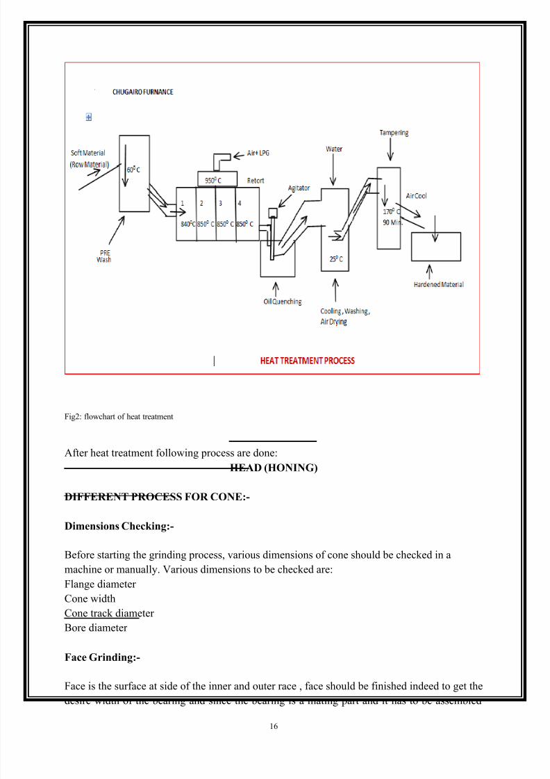
HARDENING (Heat Treatment Process)
Heat treatment process is the process of hardening the soft material. The row material is soft
material and it has to be hardened before grinding, and hardening increase the life of bearing.
Hardening is done in a special furnace named CHUGAIRO furnace.
The soft machined material is feed in the furnace and washed at 60 0 C, then send to a chamber
where the material heated in four chambers the first chamber has the temperature 840 0 C and
further chamber contains the 8500
C temperature.
Then it dipped into an oil tank at temperature 250C where the material get quenched then it
washed and then it tempered in water about 90 min. at temperature 1050 C . then dried and
cooled in air. The hardened material is obtained.
The systematic flowchart is shown in following fig:
7/27/2019 Rahul Soni's Training Report
http://slidepdf.com/reader/full/rahul-sonis-training-report 16/36
16
Fig2: flowchart of heat treatment
After heat treatment following process are done:
HEAD (HONING)
DIFFERENT PROCESS FOR CONE:-
Dimensions Checking:-
Before starting the grinding process, various dimensions of cone should be checked in a
machine or manually. Various dimensions to be checked are:
Flange diameter
Cone width
Cone track diameter
Bore diameter
Face Grinding:-
Face is the surface at side of the inner and outer race , face should be finished indeed to get the
desire width of the bearing and since the bearing is a mating part and it has to be assembled

7/27/2019 Rahul Soni's Training Report
http://slidepdf.com/reader/full/rahul-sonis-training-report 17/36
17
somewhere in the machine where it should be fit precisely. The face grinding is done in a
machine where the faces are grinded in between the grinding wheel.
Size Limit : UCL +35 µm
: LCL -35 µm
Width Variation : 5µm
There are various semi-automatic face grinding machine installed in taper section for cone
1. DAISHO MACHINE
2. NISSEI MACHINE
3. NISSEI MACHINE
OD (Outer Dia.) Grinding
OD is the circumferential surface of the outer race of the bearing. The OD should be surface
finished since the bearing has to be assembled in machine. It is obtain in an OD grinding
machine. In this machine the outer race is rotated between two grinding wheel.The outer race
is passed in machine three times to get highly finished as follows:
1. Rough1
2. Rough2
3. Fine finish
Size Limit : 15 to 35 µm
Target Size : +30 µm
Flange Grinding:-
The flange should be surface finished since the bearing has to be assembled in machine. It is
obtain in the flange grinding machine. In this machine one grinding stone is used to cut and
grind the flange portion of cone.
NC Mode - AUTO
Feed Mode - AUTO
Override - 120% (used to change machine speed.)
Tool movement during grinding is in all three dimensional axes i.e. X, Y, Z axis.

7/27/2019 Rahul Soni's Training Report
http://slidepdf.com/reader/full/rahul-sonis-training-report 18/36
18
Bore Grinding:-
Bore is the inner circumferential surface of the bearing. The bore should be surface finished
since the bearing has to be assembled in machine. It is obtain in the bore grinding machine. In
this machine the grinding stone is moved in X and Y axis.
Size Limit : +4 µm to -4 µm.
TOOL movement during grinding is in only two dimensional axes i.e. X, Z axis.
Auto Dimension Check:-
Various dimensions of cone are checked in this machine. This machine includes various
sensors for sensing the dimension of cone. This machine use weight sensors and position
sensors to identify the position and weight of cone. All dimensions should be checked in this
machine.
M1 Φ0.7 ID1 - X
M2 Φ 2.1 ID 2 - X
M3 Φ -2 TAPER
M4 Φ -0.2 ID1 - Y
M5 Φ 1.6 ID 2 – Y
M6 Φ 0.9 OVALITY
It automatically discards the work piece if its dimensions are not compatible with pre-feed
data. The limitations of size are:
Size limit : +4µm to -4 µm.
TAPER : 5 µm maximum
OOR : 5 µm maximum
CHATTER : 3 µm maximum
SQUARENESS : 5 µm maximum
Honing Machine:-
Honing is an abrasive machining process that produces a precision surface on a metal work
piece by scrubbing an abrasive stone against it along a controlled path. Honing is primarily
used to improve the geometric form of a surface, but may also improve the surface texture.

7/27/2019 Rahul Soni's Training Report
http://slidepdf.com/reader/full/rahul-sonis-training-report 19/36
19
DIFFERENT PROCESS FOR CUP:-
OD Grinding:-
OD is the circumferential surface of the outer race of the bearing. The OD should be surfacefinished since the bearing has to be assembled in machine. It is obtain in an OD grinding
machine. In this machine the outer race is rotated between two grinding wheel. The outer race
is passed in machine three times to get highly finished as follows:
Rough1, Rough2, Fine finish.
Size Limit : 15 to 35 µm
Target Size : +30 µm
Honing Machine:-
Honing is an abrasive machining process that produces a precision surface on a metal work
piece by scrubbing an abrasive stone against it along a controlled path. Honing is primarily
used to improve the geometric form of a surface, but may also improve the surface texture.

7/27/2019 Rahul Soni's Training Report
http://slidepdf.com/reader/full/rahul-sonis-training-report 20/36
20
OD GRINDING (FINISH)
ASSEMBLY LINE:-
Once respective CUP and CONE of corresponding bearing is finished, they are sent in the
Assembly line where these cup and cone get assembled with retainers having rollers in themand after some important test, they are finally packed and are ready for use.
Laser Printing Machine:-
It is a machine which is used for marking purpose of the company brand and specification on
respective cup or cone. This technology utilizes laser beam for marking. The movement of
laser beam is controlled by automatic 3d table movement. The point on metal surfaces where
these laser beams hits leave marks as required. Names of few Laser Machine which are
installed in Taper Bearing Section are:
4. AKSHAR FIBER-PRO.
5. SAJIAJANAND Laser Technology ltd.
Roll Filling Machine:-
It is an automatic machine which is actuated by pneumatic technology. In this machine, first
Retainer is placed on first station where rollers are inserted at their respective position. Then
they are sensed by position sensor, actuated by pneumatic and then cone is fixed within cage.
Pressing Machine:-
It is an automatic machine which is actuated by pneumatic and hydraulic technology both. The
Cone is pressed against Retainer with down stroke powered by hydraulics and upstroke
powered by pneumatics.
Weight check:-
At this station, Weight of bearing is checked and if the weight is not compatible with the given
standard of weight limits, machine will reject the work piece sample.
Demagnetizer:-
It is a machine which is used to remove magnetism induced during the above process. It is
done by impact hitting.
Washing: -Then the bearing is washed by fast stream of kerosene jet.

7/27/2019 Rahul Soni's Training Report
http://slidepdf.com/reader/full/rahul-sonis-training-report 21/36
21
Noise checking: -
The bearing is supposed to be produce low noise hence this machine rotates the bearing at
certain rpm and noise is checked. The noise limit is nearby 0.1 Mpa.
Press checking:-
At this station, the bearing is checked whether its assembly is pressed properly or not.
Final checking:-
This machine has 2 or 4 stations where various dimensions of final bearing are checked. If any
bearing is found incompatible with the given dimensions and tolerances, they are rejected by
the machine.
In ideal position 1, width of bearing, run out and comment or clearance of bearing is checked.
And at ideal position 2, bore size, taper and roundness are checked.
All those bearings which does not have compatible size and tolerance with the given data, they
are rejected by the machine itself.
Ideal position 1 : width, run out, comment
Ideal position 2 : bore size, bore taper, bore roundness
Oiling and Drawer Machine:-
In this machine, bearing is subjected to a fast flowing stream of coolant which is used to
lubricate the bearing parts. And then the excess oil is again sucked by the machine.
Visual Inspection:-
Now, the bearing is checked manually by the operators. All the dimensions and surface
properties are checked and rejected work piece are sent again for correction.
Packing:-
Finally, finished product is packed for market use and export.

7/27/2019 Rahul Soni's Training Report
http://slidepdf.com/reader/full/rahul-sonis-training-report 22/36
22
THE PNUEMATICS TECHNOLOGY INVOLVED IN ROLL FILLING
AND PRESS WORKING MACHINE.
In today‟s challenging environment, technology departments are in danger of being crushed
between the pincers of growing business expectation and an unstinting focus on cost control
and development.
Introduction of pneumatics:-
A fluid power system is one that transmits and control energy through the use of pressurized
liquid and gases. In pneumatics, the power comes from the atmosphere and it is reduced by
compression, thus increasing its pressure. Compressed air is mainly used to do work by acting
on a piston or vane.
Basic application of pneumatics:-
6. Operation of system valves for air, water and chemicals.
7. Lifting and moving in slab molding machine.
8. Holding in jigs and fixtures in assembly machinery and tools.
Basic pneumatic system:-
Pneumatic cylinders, rotary actuators and air motors provide the force and movement of most
Pneumatics control system, to hold, move, and form and process material.
To operate and control these actuators, other Pneumatics components are required i.e. air
service unit to prepare the compressed air and valve to control the pressure, flow2 and
direction of movement of the actuators.
A basic Pneumatics system consists of 2 main sections:
9. The air production and distribution system
10. The air consuming system
11. Air production system
12. Compressor
13. Electric motor
14. Pressure switch
15. Check valve
16. Tank
17. Pressure gauge

7/27/2019 Rahul Soni's Training Report
http://slidepdf.com/reader/full/rahul-sonis-training-report 23/36
23
18. Air dryer
19. Line filter
Air consuming system:-
20. Air take-off
21. Auto drain
22. DCV
23. Actuators
24. Speed controllers
Block diagram of roller filling and press machine:-
Major process carried out by pneumatics in roll filling and press machine:-
Main components of roll filling and press machine which are actuated by pneumatics:
25. Cage supply
26. Cage positioning
27. Roller filling in cage
28. Cage and roller assembly check
No cone
No roller Roller unit Cone supply
checkCage
positioningset press discharge
orientationtransfer
No
cage Cage supply
Cage
Assembly
Unit
Assembly
unit
No cone
No roller Roller unit Cone supply
checkCage
positioningset press discharge
orientationtransfer
No
cage Cage supply
Cage
Assembly
Unit
Assembly
unit

7/27/2019 Rahul Soni's Training Report
http://slidepdf.com/reader/full/rahul-sonis-training-report 24/36
24
29. Cone supply
30. Pressing
31. Check and discharge
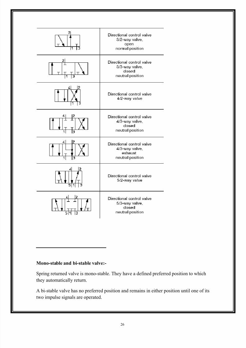
Direction control valve:-
A directional control valve determines the flow of air between its ports by opening, closing
and changing its internal connections. The valves are described in terms of the number of
ports and the number of switching position, its normal position, and the method of
operation.
The first two points are normally expressed in terms 5/2, 3/2, or 2/2etc

7/27/2019 Rahul Soni's Training Report
http://slidepdf.com/reader/full/rahul-sonis-training-report 25/36
25
7/27/2019 Rahul Soni's Training Report
http://slidepdf.com/reader/full/rahul-sonis-training-report 26/36
26
Mono-stable and bi-stable valve:-
Spring returned valve is mono-stable. They have a defined preferred position to which
they automatically return.
A bi-stable valve has no preferred position and remains in either position until one of its
two impulse signals are operated.

7/27/2019 Rahul Soni's Training Report
http://slidepdf.com/reader/full/rahul-sonis-training-report 27/36
27
Valve types:-
Poppet valve:- flow through a poppet valve is controlled by a disc or plug lifting at right
angles to a seat, with an elastic seal.
Sliding valve:- spool, rotary and plane slide valves use a sliding action to open and close
ports.
Spool valves:- a cylindrical spool slides longitudinally in the valve body with the air flowing
at right angles to the spool movement. Spools have equal sealing areas and are pressure
balanced.
Elastomeric Seal:- common seal and seal arrangements are as shown in figure. O rings are
fitted in grooves on the spool and move in a metal sleeve. Two of them are crossing output
ports, which are divided into a great number of small holes in the sleeve.
Metal seal:-
Lapped and matched metal spool and sleeve valves have very low frictional resistance,
rapid cycling and exceptionally long working life.
Plane slide valve:-
Flow through the ports is controlled by the position of a slide made of metal, nylon or other
plastic.
Direction
Control Valve
Poppet
valve
Sliding
valve
Spool
valve
Rotary
valve
Plane Slide
valve
Elastomer seal
Metal
seal
Direction
Control Valve
Poppet
valve
Sliding
valve
Spool
valve
Rotary
valve
Plane Slide
valve
Elastomer seal
Metal
seal
7/27/2019 Rahul Soni's Training Report
http://slidepdf.com/reader/full/rahul-sonis-training-report 28/36
28
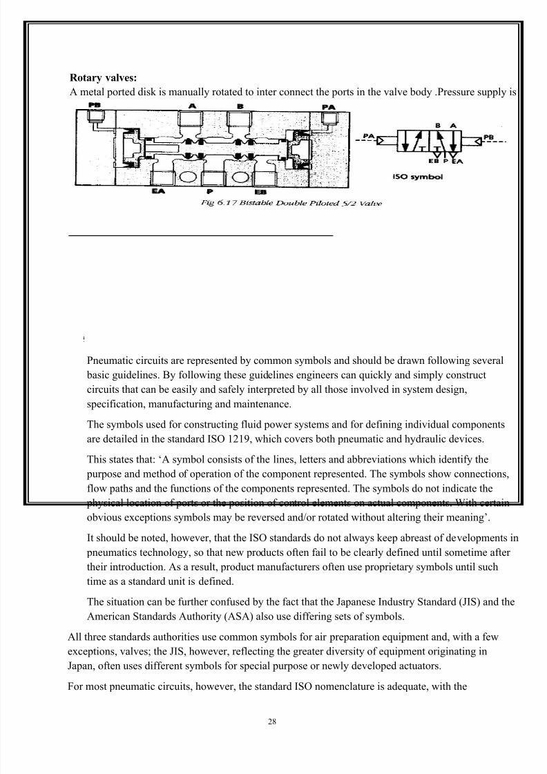
Rotary valves:
A metal ported disk is manually rotated to inter connect the ports in the valve body .Pressure supply is
above the disc.
Basic Rules For Drawing Pneumatic Circuits & Symbols
Pneumatic circuits are represented by common symbols and should be drawn following several
basic guidelines. By following these guidelines engineers can quickly and simply construct
circuits that can be easily and safely interpreted by all those involved in system design,
specification, manufacturing and maintenance.
The symbols used for constructing fluid power systems and for defining individual components
are detailed in the standard ISO 1219, which covers both pneumatic and hydraulic devices.
This states that: „A symbol consists of the lines, letters and abbreviations which identify the
purpose and method of operation of the component represented. The symbols show connections,
flow paths and the functions of the components represented. The symbols do not indicate the
physical location of ports or the position of control elements on actual components. With certain
obvious exceptions symbols may be reversed and/or rotated without altering their meaning‟.
It should be noted, however, that the ISO standards do not always keep abreast of developments in pneumatics technology, so that new products often fail to be clearly defined until sometime after
their introduction. As a result, product manufacturers often use proprietary symbols until such
time as a standard unit is defined.
The situation can be further confused by the fact that the Japanese Industry Standard (JIS) and the
American Standards Authority (ASA) also use differing sets of symbols.
All three standards authorities use common symbols for air preparation equipment and, with a few
exceptions, valves; the JIS, however, reflecting the greater diversity of equipment originating in
Japan, often uses different symbols for special purpose or newly developed actuators.
For most pneumatic circuits, however, the standard ISO nomenclature is adequate, with the

7/27/2019 Rahul Soni's Training Report
http://slidepdf.com/reader/full/rahul-sonis-training-report 29/36
29
majority of air preparation, air treatment, actuators, valves and ancillary components being
defined by common symbols.
A complete list of symbols and guidance on their construction is available.
When constructing a circuit diagram, there are always basic rules that should be followed.• The flow of working energy in a circuit diagram is drawn from the bottom to the top of the diagram
• The sequence of the working cycle is from left to right of the circuit diagram; the air supply is
therefore shown at the lower left, with the cylinder that performs the first stroke of the cycle
being situated in the upper left.
• Power valves are drawn directly below the cylinders they operate.
• All circuit components are shown in their rest position, with the supply under pressure.
• Electrical connections are not generally shown.
• Mechanically operated valves, controlling the rest position of cylinder driven parts, are operated in
the rest position and must be drawn accordingly; external connections are drawn to the valve
symbol square on the operator side.

7/27/2019 Rahul Soni's Training Report
http://slidepdf.com/reader/full/rahul-sonis-training-report 30/36
30
Fig: ISO symbols for Air Treatment Equipment

7/27/2019 Rahul Soni's Training Report
http://slidepdf.com/reader/full/rahul-sonis-training-report 31/36
31
Basic Pneumatic Circuits:-

7/27/2019 Rahul Soni's Training Report
http://slidepdf.com/reader/full/rahul-sonis-training-report 32/36
32
TROUBLESHOOTING:-
Appearance Cause Action Photo
Small indentationsaround the
raceways and
rolling elements.
Dull, worn
surfaces.
Lack of cleanliness before
and during
mounting
operation.
Do not unpackbearing until just
before it is to be
mounted. Keep
workshop clean
and use clean
tools.
Outer ring of a sphericalroller bearing with
raceways that have been
worn by abrasive
particles. It is easy to
feel where the dividing
line goes between worn
and unworn sections.
Grease discolored
green.
Ineffective seals Check and
possibly improvethe sealing.
Lubricant
contaminated by
worn particles
from brass cage
Always use fresh,
clean lubricant.
Wipe the grease
nipples. Filter the
oil.
Appearance Cause Action Photo
Worn, frequently
mirror-like, surfaces;
at a later stage blue
to brown
discoloration.
Lubrication has
gradually been
used up or has lost
its lubricating
properties.
Check that the
lubricant
reaches the
bearing.
More frequent
re lubrication.
Outer ring of a spherical
roller bearing that has
not been adequately
lubricated. The
raceways have a mirror
finish.
7/27/2019 Rahul Soni's Training Report
http://slidepdf.com/reader/full/rahul-sonis-training-report 33/36
33
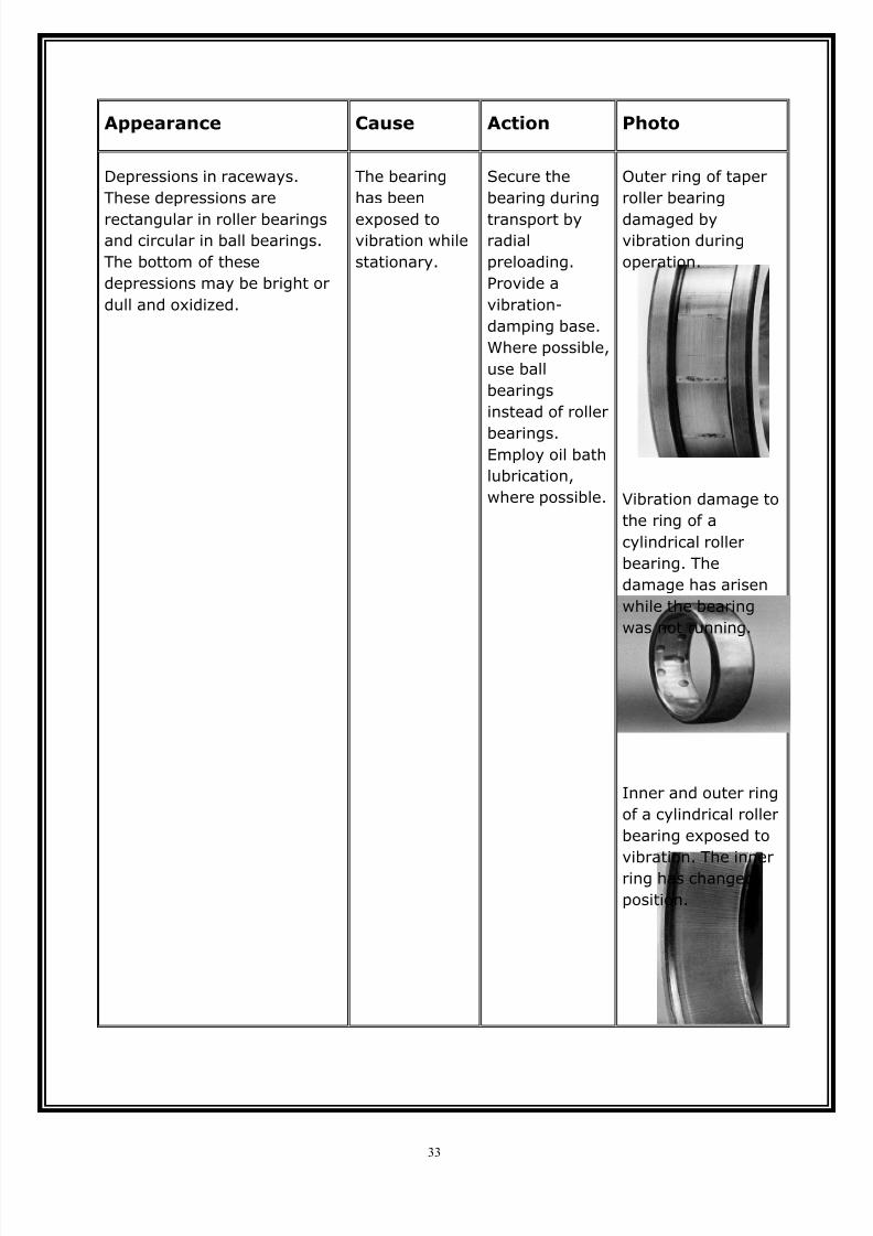
Appearance Cause Action Photo
Depressions in raceways.
These depressions are
rectangular in roller bearingsand circular in ball bearings.
The bottom of these
depressions may be bright or
dull and oxidized.
The bearing
has been
exposed tovibration while
stationary.
Secure the
bearing during
transport byradial
preloading.
Provide a
vibration-
damping base.
Where possible,
use ball
bearings
instead of roller
bearings.Employ oil bath
lubrication,
where possible.
Outer ring of taper
roller bearing
damaged byvibration during
operation.
Vibration damage to
the ring of a
cylindrical roller
bearing. The
damage has arisen
while the bearing
was not running.
Inner and outer ring
of a cylindrical roller
bearing exposed to
vibration. The inner
ring has changed
position.
7/27/2019 Rahul Soni's Training Report
http://slidepdf.com/reader/full/rahul-sonis-training-report 34/36
34
CONCLUSION
My training at NATIONAL ENGINEERING INDUSTRIES, JAIPUR was veryfruitful and I gained a lot of practical knowledge about various manufacturing
processes and techniques. I also got the opportunity to realize the challenges
faced and expertise required in manufacturing processes for mass production.
It was indeed a great experience undergoing training at the plant.

7/27/2019 Rahul Soni's Training Report
http://slidepdf.com/reader/full/rahul-sonis-training-report 35/36
35
BIBLIOGRAPHY
PLANT RECORD (Notes) : Files
A COURSE IN MECHANICAL POWER : R.K.Bansal
PROTECTION OF POWER SYSTEM : B. Ram
POWER TRANSFORMER : Tata Magr. Hill
ELECTRICAL ENGINEERING : Tata Magr. Hil
PRODUCTION ENGINEERING : P.C. Sharma
BEARING CONTENTS AND ENGINEERING: ArvindPalmgren
LUBERICATION ENGINEERING : James J.O’connor
BALL AND ROLLER BEARING ENGINEERING: Arvind Palmgren

7/27/2019 Rahul Soni's Training Report
http://slidepdf.com/reader/full/rahul-sonis-training-report 36/36
REFERENCE
WEB-SITES:-
1. www.wikipidya.com
2. www.powersystems.com
3. www.powerengg.com
4. www.protectionofelectricalsystem.com


![[Report] Narendra Modi Vs Rahul Gandhi on Social Media and Web Mentions](https://static.fdocuments.in/doc/165x107/54431c17b1af9f3d0a8b4828/report-narendra-modi-vs-rahul-gandhi-on-social-media-and-web-mentions.jpg)


![[FORMERLY RAHUL DAIRY & ALLIED PRODUCTS LTD.] 19TH …kmggroup.com/fm/96268/Annual Report 2010-2011.pdf · [FORMERLY RAHUL DAIRY & ALLIED PRODUCTS LTD.] 19TH ANNUAL REPORT 2010 -](https://static.fdocuments.in/doc/165x107/5f076ddb7e708231d41cf063/formerly-rahul-dairy-allied-products-ltd-19th-report-2010-2011pdf-formerly.jpg)