
Planning guide - GEA engineering for a better world Documents/Grasso... · fig. 18 Calculation of...
88
GEA Refrigeration Technologies Chillers with screw and reciprocating compressors (Translation of the original text) Planning guide engineering for a better world engineering for a better world
Transcript of Planning guide - GEA engineering for a better world Documents/Grasso... · fig. 18 Calculation of...
GEA Refrigeration Technologies
Chillers with screw and reciprocating compressors
(Translation of the original text)
Planning guide
engineering for a better worldengineering for a better world

COPYRIGHTAll Rights reserved.No part of this publication may be copied or pub-lished by means of printing, photocopying, microfilmor otherwise without prior written consent of
• GEA Refrigeration Germany GmbHherein after called manufacturer. This restrictionalso applies to the corresponding drawings and dia-grams.
LEGAL NOTICEThis documentation has been written in all con-science. However, the manufacturer cannot be heldresponsible, neither for any errors occurring in thisdocumentation nor for their consequences.
Technical Information | Planning GuideChillers with Screw- and Reciprocating compressors
2 GEA Refrigeration Germany GmbH | L_305511_1 | Generated 30.09.2014

SYMBOLS USED IN THIS MANUALDanger!
Stands for an immediate danger whichleads to heavy physical injuries or tothe death.
Warning!
Stands for a possibly dangerous situa-tion which leads to heavy physicalinjuries or to the death.
Caution!
Stands for a possibly dangerous situa-tion which could lead to light physicalinjuries or to damages to property.
Hint!
Stands for an important tip whoseattention is important for the designa-ted use and function of the device.
Technical Information | Planning GuideChillers with Screw- and Reciprocating compressors
GEA Refrigeration Germany GmbH | L_305511_1 | Generated 30.09.2014 3

PREFACEInstalling liquid chillers in the member states ofthe European UnionEN 378 requirementsEuropean directives serve the requirements ofmachines, systems and services and favour a freeturnover of goods and services within the EuropeanUnion. The Member States of the European Unionare obliged to transfer the contents of the directivesinto national law. So-called Harmonized Norms (EN)are published explaining the requirements of thedirectives for the purpose of supporting and instigat-ing the directives.In the field of refrigeration technology, the Norm EN378 is of particular relevance. In its four parts, therequirements for the safety of persons and property,as well as the local and global environment, aredetermined for stationary and mobile refrigeratingsystems and heat pumps of any size. This leafletacquaints the reader with the EN 378 requirementsfor chillers and provides a general overview of therequirements placed upon both the system installa-tion and refrigerant selection.In the Member States of the European Union, addi-tional regulations may prevail (e.g. BGR 500/2.36 inGermany).
Technical Information | Planning GuideChillers with Screw- and Reciprocating compressors
4 GEA Refrigeration Germany GmbH | L_305511_1 | Generated 30.09.2014

TABLE OF CONTENTS1 INTRODUCTION 9
1.1 Refrigerant circuit 101.2 Efficiency 12
2 MACHINE AND PLANT TECHNOLOGY 172.1 Basic series of chillers 17
2.1.1 Water cooled chiller for inside installation with an external heat exchanger 172.1.2 Chiller in remote execution for inside installation with external air cooled condenser 182.1.3 Air cooled chiller for outside installation 19
2.2 Selection criteria and operation limits 202.3 Anti-freeze and glycol 242.4 Refrigerant 25
2.4.1 Refrigerant classes 252.4.2 Technical facts 262.4.3 Refrigerants and environmental protection 27
2.5 Chillers in remote execution 282.5.1 Oil cooling using the thermosyphon principal 282.5.2 Remote condenser 31
3 INSTALLATION 343.1 Machinery room (acc. to EN 378: Special Machinery Rooms) 343.2 Installation areas 343.3 Examples of machinery room arrangements 353.4 Installation in buildings 363.5 Refrigerant fill up depending on system installation site 383.6 Practical Limits for different refrigerants 403.7 Comparison between Ammonia systems and refrigerating systems with L1-refrigerant charges 413.8 Airborne and structure-borne sound 453.9 Chillers using ammonia as a cooling medium. 49
4 REQUIREMENTS OF HYDRAULIC CIRCUITS 504.1 Requirements for the hydraulic circuit 504.2 Application: Chiller in the consumer circuit 514.3 Application instruction for the installation of the flow switch and temperature sensor for the cooling
agent outlet temperature 544.4 Application: Cooling medium circuit 554.5 Pipes / insulations 564.6 Water quality requirements, parameters 594.7 Use of filters 61
5 ELECTRICS REQUIREMENTS 625.1 Network systems 62
5.1.1 TN-S system 635.1.2 TN-C system 645.1.3 TN-C-S system 655.1.4 TT system 665.1.5 IT system 67
5.2 Starting modes – motor 685.2.1 Direct start up 685.2.2 Star/delta starting 705.2.3 Soft starter 725.2.4 Frequency inverter 74
5.3 Protection against accidental contact, solid foreign bodies and water 785.4 The control accuracy of chillers 815.5 Communication 835.6 Input signals and output signals 84
6 STANDARDS AND GUIDELINES 85
Technical Information | Planning GuideChillers with Screw- and Reciprocating compressors
GEA Refrigeration Germany GmbH | L_305511_1 | Generated 30.09.2014 5

Technical Information | Planning GuideChillers with Screw- and Reciprocating compressors
6 GEA Refrigeration Germany GmbH | L_305511_1 | Generated 30.09.2014

TABLE OF FIGURESfig. 1 Refrigerant circuit 10fig. 2 Calculation of water condensation heat 10fig. 3 Calculation of the refrigerating capacity figure 12fig. 4 Calculation of the heat capacity figure 12fig. 5 Efficiency in the case of water cooled chillers 13fig. 6 IPLV calculation 14fig. 7 ESEER calculation 14fig. 8 Weighting of the load stages in ESEER and IPLV 15fig. 9 Example ESEER procedures for GEA Grasso chillers 16fig. 10 Inside installation of water cooled chiller with external heat exchanger 17fig. 11 Inside installation of an air cooled chiller with external condenser 18fig. 12 Outside installation of air cooled chiller 19fig. 13 Temperature distribution in days in Berlin for 2013 20fig. 14 Operation limits 22fig. 15 Composition of refrigerants 25fig. 16 Technical facts of the refrigerants 26fig. 17 Thermosyphon oil circuit 28fig. 18 Calculation of the minimum height to be kept 29fig. 19 Blocking the external vapour condenser. 31fig. 20 Blocking the external air cooled condenser 32fig. 21 Blocking the external air cooled condenser for oil cooling via a separate refrigerant circuit.
33fig. 22 Machinery room arrangement, example 1 35fig. 23 Machinery room arrangement, example 2 35fig. 24 Installation on 1st basement floor 36fig. 25 Installation on 2nd basement floor 36fig. 26 Installation on upper floor 37fig. 27 Calculation of air volume for the mechanical ventilation 42fig. 28 Calculation of air volume for removal of waste heat 43fig. 29 Sound distribution 46fig. 30 Hydraulic circuit with dual circuit buffer tank 51fig. 31 Calculation of the tank volume 52fig. 32 Calculation of the volume flow of the primary circuit-cooling agent pump 52fig. 33 Calculation of the total volume flow of the consumer circuit 53fig. 34 Cooling agent system 54fig. 35 Influence of the flow speed on pressure loss and power requirement 56fig. 36 Corrosion resistance in presence of chlorides 60fig. 37 TN-S system 230/ 400 V 63fig. 38 TN-C system 230/ 400 V 64fig. 39 TN-C-S system 230/ 400 V 65fig. 40 TT system 230/ 400 V 66fig. 41 IT system 230/ 400/ 500/ 690 V 67fig. 42 Direct start up - voltage curve 68fig. 43 Direct start up - current curve 68fig. 44 Direct start up - torque curve 69fig. 45 Star/delta starting - voltage curve 70fig. 46 Star/delta starting - current curve 70fig. 47 Star/delta starting - torque curve 71fig. 48 Soft starter - voltage curve 72fig. 49 Soft starter - current curve 73fig. 50 Soft starter - torque curve 73fig. 51 Frequency inverter - voltage curve 74fig. 52 Frequency inverter - current curve 75fig. 53 Frequency inverter - torque curve 75fig. 54 Approach of the process size to the setpoint after variations in the customer side cold
water circuit 82fig. 55 Input signals and output signals for a GEA Grasso BluAstrum 84
Technical Information | Planning GuideChillers with Screw- and Reciprocating compressors
GEA Refrigeration Germany GmbH | L_305511_1 | Generated 30.09.2014 7

Technical Information | Planning GuideChillers with Screw- and Reciprocating compressors
8 GEA Refrigeration Germany GmbH | L_305511_1 | Generated 30.09.2014
1 INTRODUCTION
The foundations of refrigeration technology are the laws of thermodynamics.1st law:Energy cannot be created or destroyed but can only be converted from one form into another, for example heatinto effort.2nd law:Heat always only flows from a system with a higher temperature into a system with a lower temperature andnever the other way round.
However, in order to cool heat must be brought from a lower to a higher temperature level.If you consider the 2nd law of thermodynamics in its definition according to Rudolf Clausius, the followingapplies:If water at 12 °C (cooling agent) is cooled to 6 °C and the heat to be removed Qo is brought to a higher tempera-ture level, this is only possible by supplying energy to the compressor motor.In refrigeration technology, a liquid with a low boiling point is used as a means of transporting heat. The so-called refrigerant has the property of evaporating under heat absorption at low pressure and low temperatureand of condensing under heat dissipation at high pressure and high temperature.
Technical Information | Planning GuideChillers with Screw- and Reciprocating compressors
Introduction
GEA Refrigeration Germany GmbH | L_305511_1 | Generated 30.09.2014 9
1.1 Refrigerant circuit
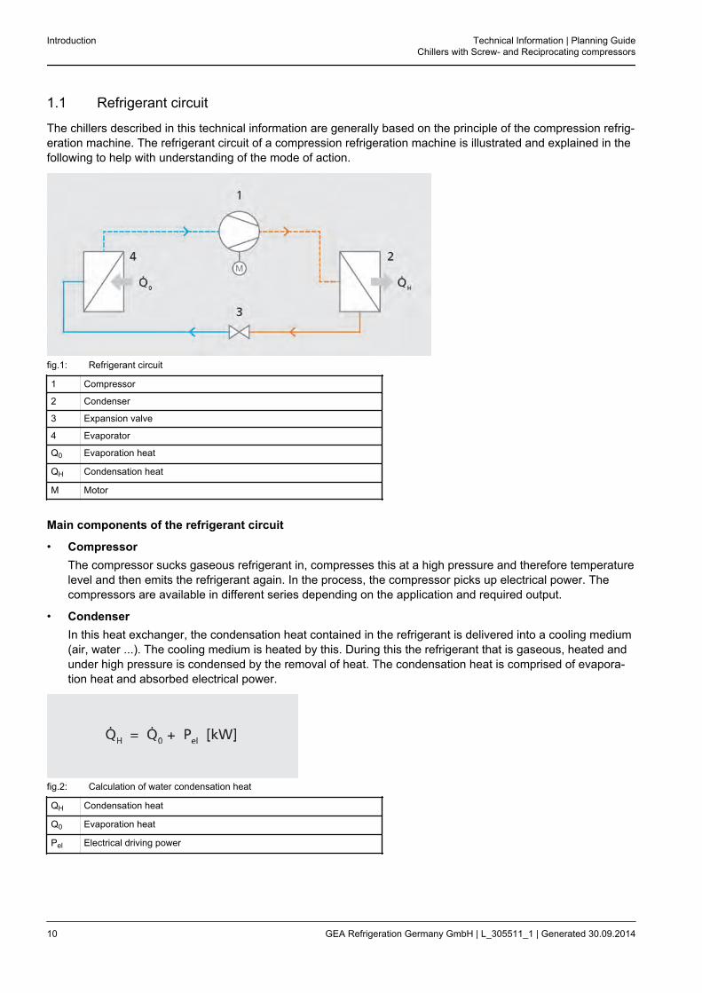
The chillers described in this technical information are generally based on the principle of the compression refrig-eration machine. The refrigerant circuit of a compression refrigeration machine is illustrated and explained in thefollowing to help with understanding of the mode of action.
fig.1: Refrigerant circuit
1 Compressor
2 Condenser
3 Expansion valve
4 Evaporator
Q0 Evaporation heat
QH Condensation heat
M Motor
Main components of the refrigerant circuit
• CompressorThe compressor sucks gaseous refrigerant in, compresses this at a high pressure and therefore temperaturelevel and then emits the refrigerant again. In the process, the compressor picks up electrical power. Thecompressors are available in different series depending on the application and required output.
• CondenserIn this heat exchanger, the condensation heat contained in the refrigerant is delivered into a cooling medium(air, water ...). The cooling medium is heated by this. During this the refrigerant that is gaseous, heated andunder high pressure is condensed by the removal of heat. The condensation heat is comprised of evapora-tion heat and absorbed electrical power.
fig.2: Calculation of water condensation heat
QH Condensation heat
Q0 Evaporation heat
Pel Electrical driving power
Introduction Technical Information | Planning GuideChillers with Screw- and Reciprocating compressors
10 GEA Refrigeration Germany GmbH | L_305511_1 | Generated 30.09.2014
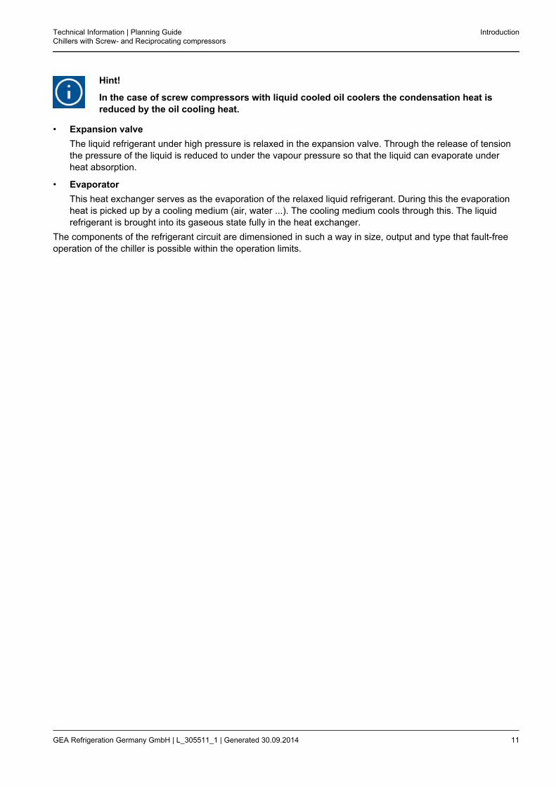
Hint!
In the case of screw compressors with liquid cooled oil coolers the condensation heat isreduced by the oil cooling heat.
• Expansion valveThe liquid refrigerant under high pressure is relaxed in the expansion valve. Through the release of tensionthe pressure of the liquid is reduced to under the vapour pressure so that the liquid can evaporate underheat absorption.
• EvaporatorThis heat exchanger serves as the evaporation of the relaxed liquid refrigerant. During this the evaporationheat is picked up by a cooling medium (air, water ...). The cooling medium cools through this. The liquidrefrigerant is brought into its gaseous state fully in the heat exchanger.
The components of the refrigerant circuit are dimensioned in such a way in size, output and type that fault-freeoperation of the chiller is possible within the operation limits.
Technical Information | Planning GuideChillers with Screw- and Reciprocating compressors
Introduction
GEA Refrigeration Germany GmbH | L_305511_1 | Generated 30.09.2014 11

1.2 Efficiency
Due to ever rising energy costs, attention in Europe is increasingly turning to efficiency and the energy consump-tion of electrical devices. The following output figures are used to compare efficiency between different chillers.
Hint!
Full load efficiencyIn the case of chillers and heat pumps the energy efficiency at full load is expressed by theoutput figures EER (Energy Efficiency Ratio) and COP (Coefficient of Performance).
EER (Energy Efficiency Ratio)In the case of chillers the refrigerating capacity figure is the quotient of rated cooling capacity and electric drivingpower.
fig.3: Calculation of the refrigerating capacity figure
EER Refrigerating capacity figure
Q0 Rated cooling capacity
Pel Electrical driving power
COP (Coefficient of Performance)In the case of heat pumps the heat capacity figure is the quotient of rated heating capacity and electric drivingpower.
fig.4: Calculation of the heat capacity figure
COP Heat capacity figure
QH Rated heating capacity
Pel Electrical driving power
However, it must be taken into account that the efficiency level of such a chiller can vary considerably. The effi-ciency is dependent on the part-load of the chiller and the operating conditions in the evaporator and in the con-denser. Particularly in the case of chillers with many part load stages the full load operation is usually onlyreached on a few days in the year. In such cases the annual efficiency needs to be considered.
Hint!
Efficiency and operating conditionsDuring the operating phase of a chiller variable loads occur which have a direct effect on theefficiency.The refrigerating capacity and power consumption change depending on the power stage,cold water temperature, cooling water temperature or intake air temperature.
Introduction Technical Information | Planning GuideChillers with Screw- and Reciprocating compressors
12 GEA Refrigeration Germany GmbH | L_305511_1 | Generated 30.09.2014

The efficiency of the chiller increases if the cooling medium inlet temperature is decreased, e.g. cooling water orintake air temperature and if the cooling agent outlet temperature is increased.Generously dimensioned heat exchangers (cooler, heat exchanger) improve the efficiency of a chiller.
fig.5: Efficiency in the case of water cooled chillers
X Cooling water inlet temperature in °C
Y EER
A Cold water outlet temperature in °C
In addition to the already mentioned optimization possibilities, installation locations that are protected from thesun are beneficial for air cooled chillers installed outside.Optimization of operation does have its limits, however.The operation limits of chillers (see chapter installation areas) are indicated by the manufacturer and it is impera-tive that they are already observed during the planning phase.
Hint!
Annual efficiencyFor some years, the efficiency for rated conditions (full load) has not only been referred to forchillers.An evaluation index is used which takes into account both the operation of the chiller underrated conditions and use under part load conditions.For part load the outside air temperature is under the original design temperature and thechiller works with reduced power.
IPLVThe evaluation index used in the USA is called IPLV (Integrated Part Load Value) and is defined in a regulationissued by ARI (American Refrigeration Institute).
Technical Information | Planning GuideChillers with Screw- and Reciprocating compressors
Introduction
GEA Refrigeration Germany GmbH | L_305511_1 | Generated 30.09.2014 13

fig.6: IPLV calculation
IPLV Evaluation index
EER Refrigerating capacity figure
Where EER 100%, EER 75%, EER 50%, EER 25% is for the efficiencies of the chiller under the different partload conditions (100% - 75% - 50% and 25%) which are calculated for the lower outside temperature conditionsor cooling water inlet temperatures.The part load conditions are presented in the following.
Temperature of cooling medium (air/water) according to IPLV; cooling agent outlet 6.7 °C
Load 100 % 75 % 50 % 25 %
Cooling water inlet temperature 29.4 °C 23.9 °C 18.3 °C 18.3 °C
Outside air temperature 35 °C 26.7 °C 18.3 °C 12.8 °C
ESEERIn Europe, the EECCAC (Energy Efficiency and Certification of Central Air Conditioner) study was carried out toadapt the IPLV which relates to the American climate to European conditions.In the process ESEER (European Seasonal Energy Efficiency Ratio) was developed.
fig.7: ESEER calculation
ESEER European Seasonal Energy Efficiency Ratio
EER Refrigerating capacity figure
Where EER 100%, EER 75%, EER 50%, EER 25% is for the efficiencies of the chiller under the different partload conditions (100% - 75% - 50% and 25%) which are calculated for the lower outside temperature conditionsor cooling water inlet temperatures.The part load conditions are presented in the following.
Temperature of cooling medium (air/water) according to ESEER; cooling agent outlet 7 °C
Load 100 % 75 % 50 % 25 %
Cooling water inlet temperature 30 °C
Outside air temperature 35 °C
Introduction Technical Information | Planning GuideChillers with Screw- and Reciprocating compressors
14 GEA Refrigeration Germany GmbH | L_305511_1 | Generated 05.11.2014
Mueller.ka
Schreibmaschinentext
26 °C
Mueller.ka
Schreibmaschinentext
22 °C
Mueller.ka
Schreibmaschinentext
18 °C
Mueller.ka
Schreibmaschinentext
20 °C
Mueller.ka
Schreibmaschinentext
30 °C
Mueller.ka
Schreibmaschinentext
25 °C
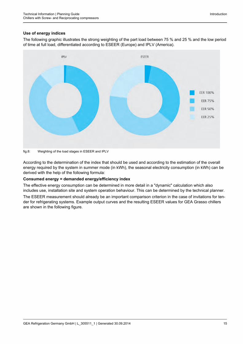
Use of energy indicesThe following graphic illustrates the strong weighting of the part load between 75 % and 25 % and the low periodof time at full load, differentiated according to ESEER (Europe) and IPLV (America).
fig.8: Weighting of the load stages in ESEER and IPLV
According to the determination of the index that should be used and according to the estimation of the overallenergy required by the system in summer mode (in kWh), the seasonal electricity consumption (in kWh) can bederived with the help of the following formula:Consumed energy = demanded energy/efficiency indexThe effective energy consumption can be determined in more detail in a "dynamic" calculation which alsoincludes use, installation site and system operation behaviour. This can be determined by the technical planner.The ESEER measurement should already be an important comparison criterion in the case of invitations for ten-der for refrigerating systems. Example output curves and the resulting ESEER values for GEA Grasso chillersare shown in the following figure.
Technical Information | Planning GuideChillers with Screw- and Reciprocating compressors
Introduction
GEA Refrigeration Germany GmbH | L_305511_1 | Generated 30.09.2014 15

fig.9: Example ESEER procedures for GEA Grasso chillers
X Load levels
Y EER
A BluGenium 1200 (12/7); ESEER > 9.5
B BluAstrum 1000 (12/7); ESEER 8.1
C BluAstrum 1000 (12/6); ESEER 7.7
D FX P (12/7) without VSD; ESEER 6.1
E BluAir 1000 (12/7); ESEER 5.6
Introduction Technical Information | Planning GuideChillers with Screw- and Reciprocating compressors
16 GEA Refrigeration Germany GmbH | L_305511_1 | Generated 30.09.2014
2 MACHINE AND PLANT TECHNOLOGY
2.1 Basic series of chillers
The systems listed in the following are basic series and serve to illustrate the installation possibilities for chillers.The hydraulic solution is presented as a dual circuit system. The chiller supplies the primary circuit. The tankssupplies the secondary circuit (consumer circuit).
2.1.1 Water cooled chiller for inside installation with an external heat exchanger
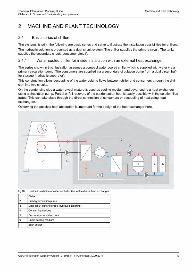
The series shown in this illustration assumes a compact water cooled chiller which is supplied with water via aprimary circulation pump. The consumers are supplied via a secondary circulation pump from a dual circuit buf-fer storage (hydraulic separator).This construction allows decoupling of the water volume flows between chiller and consumers through the divi-sion into two circuits.On the condensing side a water-glycol mixture is used as cooling medium and advanced to a heat exchangerusing a circulation pump. Partial or full recovery of the condensation heat is easily possible with the solution illus-trated. This can take place through the direct connection of consumers or decoupling of heat using heatexchangers.Observing the possible heat absorption is important for the design of the heat exchanger here.
fig.10: Inside installation of water cooled chiller with external heat exchanger
1 Chiller
2 Primary circulation pump
3 Dual circuit buffer storage (hydraulic separator)
4 Consuming devices
5 Secondary circulation pump
6 Pump cooling medium
7 Back cooler
Technical Information | Planning GuideChillers with Screw- and Reciprocating compressors
Machine and plant technology
GEA Refrigeration Germany GmbH | L_305511_1 | Generated 30.09.2014 17

2.1.2 Chiller in remote execution for inside installation with external air cooled condenser
A split chiller, a series that is equipped with an evaporator, is supplied with water via a primary circulation pump.The consumers are supplied via a secondary circulation pump from a dual circuit buffer storage (hydraulic sepa-rator).
fig.11: Inside installation of an air cooled chiller with external condenser
1 Chiller
2 Primary circulation pump
3 Dual circuit buffer storage (hydraulic separator)
4 Consuming devices
5 Secondary circulation pump
6 Condenser
Machine and plant technology Technical Information | Planning GuideChillers with Screw- and Reciprocating compressors
18 GEA Refrigeration Germany GmbH | L_305511_1 | Generated 30.09.2014

2.1.3 Air cooled chiller for outside installation
The series shown in this illustration assumes a compact air cooled chiller which is supplied with water or water-glycol mixture with a circulation pump. The consumers are directly supplied, a dual circuit buffer storage is instal-led for load balancing.The entire water circuit needs to be protected against freezing for the series illustrated. Alternatively the watercircuit can additionally be equipped with a heat exchanger to divide into frost-protected external area and internalareas.
fig.12: Outside installation of air cooled chiller
1 Chiller
2 Primary circulation pump
3 Dual circuit buffer storage (hydraulic separator)
4 Consuming devices
5 Secondary circulation pump
The systems listed above are basic series and serve to illustrate the installation possibilities for chillers. Thehydraulic solution – single or dual circuit system – can be used independently of the series of chiller.
Technical Information | Planning GuideChillers with Screw- and Reciprocating compressors
Machine and plant technology
GEA Refrigeration Germany GmbH | L_305511_1 | Generated 30.09.2014 19
2.2 Selection criteria and operation limits
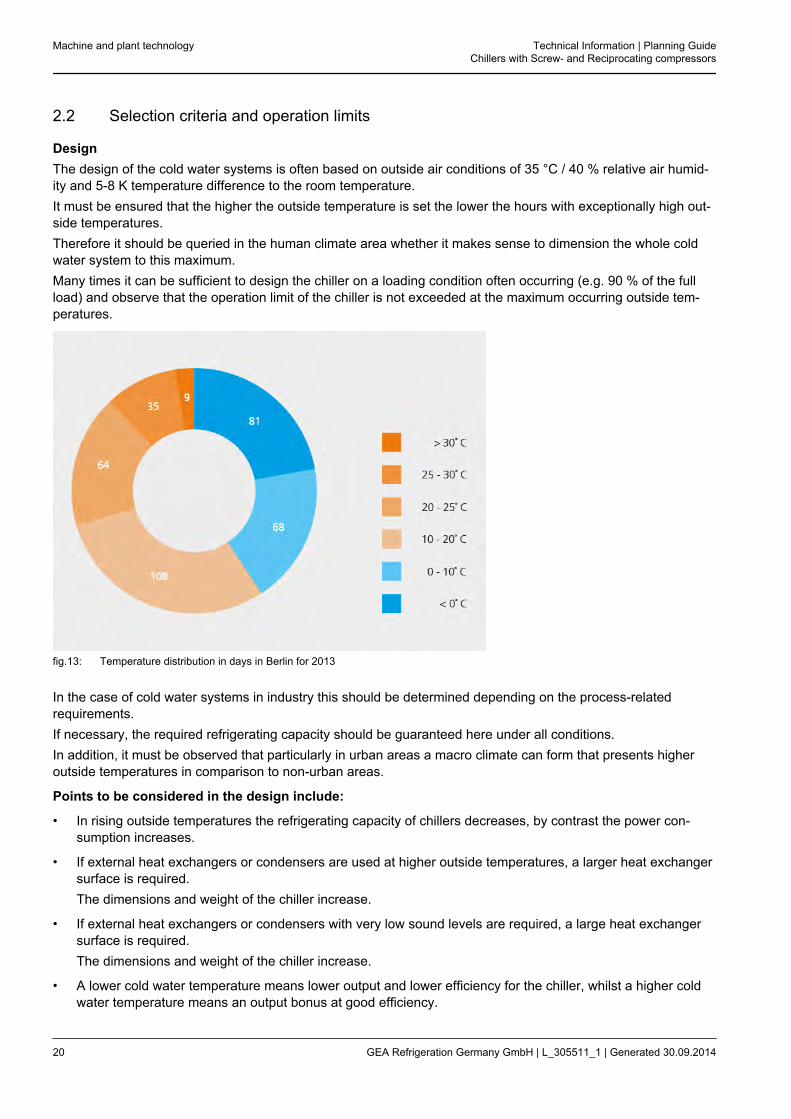
DesignThe design of the cold water systems is often based on outside air conditions of 35 °C / 40 % relative air humid-ity and 5-8 K temperature difference to the room temperature.It must be ensured that the higher the outside temperature is set the lower the hours with exceptionally high out-side temperatures.Therefore it should be queried in the human climate area whether it makes sense to dimension the whole coldwater system to this maximum.Many times it can be sufficient to design the chiller on a loading condition often occurring (e.g. 90 % of the fullload) and observe that the operation limit of the chiller is not exceeded at the maximum occurring outside tem-peratures.
fig.13: Temperature distribution in days in Berlin for 2013
In the case of cold water systems in industry this should be determined depending on the process-relatedrequirements.If necessary, the required refrigerating capacity should be guaranteed here under all conditions.In addition, it must be observed that particularly in urban areas a macro climate can form that presents higheroutside temperatures in comparison to non-urban areas.
Points to be considered in the design include:
• In rising outside temperatures the refrigerating capacity of chillers decreases, by contrast the power con-sumption increases.
• If external heat exchangers or condensers are used at higher outside temperatures, a larger heat exchangersurface is required.The dimensions and weight of the chiller increase.
• If external heat exchangers or condensers with very low sound levels are required, a large heat exchangersurface is required.The dimensions and weight of the chiller increase.
• A lower cold water temperature means lower output and lower efficiency for the chiller, whilst a higher coldwater temperature means an output bonus at good efficiency.
Machine and plant technology Technical Information | Planning GuideChillers with Screw- and Reciprocating compressors
20 GEA Refrigeration Germany GmbH | L_305511_1 | Generated 30.09.2014

• An important criterion in the human climate area is the necessity of dehumidification. The larger the powerproportion for dehumidification needs to be, the lower the cold water temperature should be set.If no or only a lower dehumidification proportion is required, the cold water temperature could be selectedhigher.In practice an efficient balance between cold water temperature and larger heat exchanger surface on theconsumers results. For example, this can be used positively with systems for thermal activation.
The cold water temperature mostly results from the specification of the processes in industry.
Hint!
The use of glycol instead of water in the cold water circuit partly requires significantlyincreased heat exchanger surfaces on the consumers.
Operation limits of chillersThe operation limits of chillers primarily depend on the respective construction parameters of the individual com-ponents. These are in particular design pressure, design temperature and the required pressure differences forpressure limited components.
Design pressureThe design pressure of the pressure-relevant components of a chiller therefore gives the maximum condens-ing temperature of the chiller, depending on the respective selected refrigerant. The GEA Grasso chillers areoptimized for the use of natural refrigerant, ammonia. The standard design pressure is either 25 bar (recipro-cating compressor) or 28 bar (screw compressor) depending on the compressor type.
Design temperatureThe design temperature of the components used indicates in particular the lower operation limit, thereforethe minimum evaporating temperature of the chiller. The possible minimum design temperature for the chill-ers depends fundamentally on the materials used. The use of the relevant suitable materials by the manu-facturer makes a minimum design temperature of up to -45 °C possible.
Maximum possible operating pressureTo secure all components against excess pressure (incident) some pressure limited components are instal-led next to the control of the chiller (pressure switch, overflow valve, safety valve). These components in theso called safety chain are addressed by building pressure in stages, if necessary. In order to ensure theirfunction, a certain pressure range to the next relevant component should be kept. This safety chain normallycalls for a pressure range of 4-5 bar under the maximum operating pressure PS.
To define generally valid operation limits of GEA Grasso chillers, the relevant permitted limits of the evaporatingand condensing temperature are most suitable. This approach allows the graphic illustration of "operation limits"of all deliverable chillers, independent from the type of condensing of the refrigerant. The then relevant possibletemperatures/temperature differences on the cooling agent side (evaporator) and on the side of the coolingmedium (condenser) depend on the components used and the fluids.
Technical Information | Planning GuideChillers with Screw- and Reciprocating compressors
Machine and plant technology
GEA Refrigeration Germany GmbH | L_305511_1 | Generated 30.09.2014 21
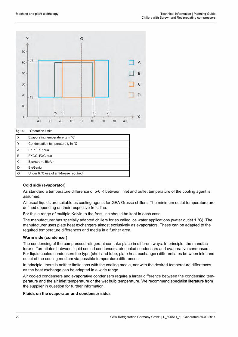
fig.14: Operation limits
X Evaporating temperature t0 in °C
Y Condensation temperature tc in °C
A FXP, FXP duo
B FXGC, FXG duo
C BluAstrum, BluAir
D BluGenium
G Under 0 °C use of anti-freeze required
Cold side (evaporator)As standard a temperature difference of 5-6 K between inlet and outlet temperature of the cooling agent isassumed.All usual liquids are suitable as cooling agents for GEA Grasso chillers. The minimum outlet temperature aredefined depending on their respective frost line.For this a range of multiple Kelvin to the frost line should be kept in each case.The manufacturer has specially adapted chillers for so called ice water applications (water outlet 1 °C). Themanufacturer uses plate heat exchangers almost exclusively as evaporators. These can be adapted to therequired temperature differences and media in a further area.
Warm side (condenser)The condensing of the compressed refrigerant can take place in different ways. In principle, the manufac-turer differentiates between liquid cooled condensers, air cooled condensers and evaporative condensers.For liquid cooled condensers the type (shell and tube, plate heat exchanger) differentiates between inlet andoutlet of the cooling medium via possible temperature differences.In principle, there is neither limitations with the cooling media, nor with the desired temperature differencesas the heat exchange can be adapted in a wide range.Air cooled condensers and evaporative condensers require a larger difference between the condensing tem-perature and the air inlet temperature or the wet bulb temperature. We recommend specialist literature fromthe supplier in question for further information.
Fluids on the evaporator and condenser sides
Machine and plant technology Technical Information | Planning GuideChillers with Screw- and Reciprocating compressors
22 GEA Refrigeration Germany GmbH | L_305511_1 | Generated 30.09.2014

A series of liquids are available as suitable fluids on the cold and warm sides. In first place is water as wateris inexpensive and is equipped with optimal material properties. Only the frost line of 0 °C is disadvanta-geous and, depending on the water quality, the corrosion tendency for stainless steels. (see chapter "Waterquality requirements, parameters").
Technical Information | Planning GuideChillers with Screw- and Reciprocating compressors
Machine and plant technology
GEA Refrigeration Germany GmbH | L_305511_1 | Generated 30.09.2014 23

2.3 Anti-freeze and glycol
For cold water systems in which chillers or cooling plants are used and these devices and component parts areoutside, anti-freeze must be paid particular attention.If water temperatures of under +4 °C can occur in the system, the following measures are possible for protectionagainst freezing.
1. Use of glycols or brinesHere, the influences on changes in technical properties in the cold water system should be considered.
2. Electric anti-freeze heatersAll water carrying components must be insulated and equipped with anti-freeze heaters and pipe trace heat-ers.
Hint!
A separate feed is required so that the protective function is also ensured in the case of thesystem being switched off.
3. Draining of the cold water system outside of the cooling periodThe measures under Points 1 and 2 can be done away with if a cooling operation is not longer requiredunder +6 °C.However, here the annual costs and time required for draining and refilling of the cold water system shouldbe considered and the increased corrosion from drained components be taken into account.
The method most used in practice is the use of anti-freeze. Here, depending on requirement and usage, ethyl-ene glycol, propylene glycol, temper or ethanol mixtures are used.The mixture ratio is calculated as follows (example):
Mixture ratio
Frost protection to Proportion ethylene glycol (vol. %)
-10 °C 20 %
-20 °C 34 %
-30 °C 44 %
-40 °C 52 %
In principle the influences described in the following in the planning and design of cold water system should beconsidered.
Hint!
• Anti-freeze in water circuits change the technical properties of products depending on the typeand concentration:e.g. of pipes, fittings, valves, water filters, heat exchangers, heating and cooling devices, pumps,chillers, heat pumps.
• Most pressure drop increases occurring lead to lower output in coolers, heaters and pumps.
• The higher the kinematic viscosity is the larger these influences are.
Machine and plant technology Technical Information | Planning GuideChillers with Screw- and Reciprocating compressors
24 GEA Refrigeration Germany GmbH | L_305511_1 | Generated 30.09.2014

2.4 Refrigerant
2.4.1 Refrigerant classes
Refrigerants will be classed according to their flammability and toxicity.The following table gives an overview the classes of refrigerants in chillers used by the manufacturer. See alsoEN 378-1:2012-08; Appendix E.
Refrigerant classes
Safety group Refrigerant
A1 - low toxicity - no flame propagation R134a, R404A, R407C, R410A, R507A, CO2
B2 - increased toxicity - low flame propagation ammonia/ R717
For chillers, depending on the output size and the type of compressor the chlorine-free HFC refrigerant R134a,R407C, R410A and the natural refrigerant ammonia (R717) have been established. In contrast to R134a, therefrigerants R407C and R410A are non-azeotropic refrigerants. They are mixtures comprising of different singlecomponent refrigerants.
fig.15: Composition of refrigerants
A R134a
B R407C
C R410A
D R717
E R32
F R125
Technical Information | Planning GuideChillers with Screw- and Reciprocating compressors
Machine and plant technology
GEA Refrigeration Germany GmbH | L_305511_1 | Generated 30.09.2014 25

2.4.2 Technical facts
In comparison to these four refrigerants, a cooling system at the same output and same conditions in relation tocompressors, heat exchangers etc. requires optimized components for the respective refrigerants.
fig.16: Technical facts of the refrigerants
1 Pressure ratio pc/po
2 Differential pressure pc=po
3 Volumetric refrigerating capacity
A R134a
B R407C
C R410A
D R717
Due to the high working pressure of the refrigerant R410A particular requirements are placed on pressure stabil-ity here. Despite the high working pressure the required swept volume for R408C, ammonia and in particularR410A is lower due to the higher volumetric refrigerating capacity.
Machine and plant technology Technical Information | Planning GuideChillers with Screw- and Reciprocating compressors
26 GEA Refrigeration Germany GmbH | L_305511_1 | Generated 30.09.2014
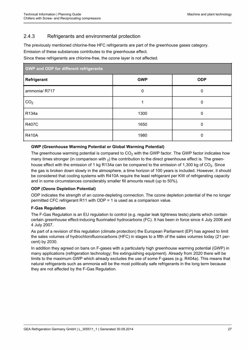
2.4.3 Refrigerants and environmental protection
The previously mentioned chlorine-free HFC refrigerants are part of the greenhouse gases category.Emission of these substances contributes to the greenhouse effect.Since these refrigerants are chlorine-free, the ozone layer is not affected.
GWP and ODP for different refrigerants
Refrigerant GWP ODP
ammonia/ R717 0 0
CO2 1 0
R134a 1300 0
R407C 1650 0
R410A 1980 0
GWP (Greenhouse Warming Potential or Global Warming Potential)The greenhouse warming potential is compared to CO2 with the GWP factor. The GWP factor indicates howmany times stronger (in comparison with 2) the contribution to the direct greenhouse effect is. The green-house effect with the emission of 1 kg R134a can be compared to the emission of 1,300 kg of CO2. Sincethe gas is broken down slowly in the atmosphere, a time horizon of 100 years is included. However, it shouldbe considered that cooling systems with R410A require the least refrigerant per KW of refrigerating capacityand in some circumstances considerably smaller fill amounts result (up to 50%).
ODP (Ozone Depletion Potential)ODP indicates the strength of an ozone-depleting connection. The ozone depletion potential of the no longerpermitted CFC refrigerant R11 with ODP = 1 is used as a comparison value.
F-Gas RegulationThe F-Gas Regulation is an EU regulation to control (e.g. regular leak tightness tests) plants which containcertain greenhouse effect-inducing fluorinated hydrocarbons (FC). It has been in force since 4 July 2006 and4 July 2007.As part of a revision of this regulation (climate protection) the European Parliament (EP) has agreed to limitthe sales volumes of hydrochlorofluorocarbons (HFC) in stages to a fifth of the sales volumes today (21 per-cent) by 2030.In addition they agreed on bans on F-gases with a particularly high greenhouse warming potential (GWP) inmany applications (refrigeration technology; fire extinguishing equipment). Already from 2020 there will belimits to the maximum GWP which already excludes the use of some F-gases (e.g. R404a). This means thatnatural refrigerants such as ammonia will be the most politically safe refrigerants in the long term becausethey are not affected by the F-Gas Regulation.
Technical Information | Planning GuideChillers with Screw- and Reciprocating compressors
Machine and plant technology
GEA Refrigeration Germany GmbH | L_305511_1 | Generated 30.09.2014 27
2.5 Chillers in remote execution
In addition to the chillers completely equipped ex works with a condenser, so called remote chillers are oftenalso operated.This means that the chiller delivered ex works does not contain a condenser but has only been designed for therequested condensation temperature.The customer himself then selects a suitable condenser and connects this with the supplied remote chiller. Theexternal (remote) condenser is either an air cooled condenser or an evaporative condenser.
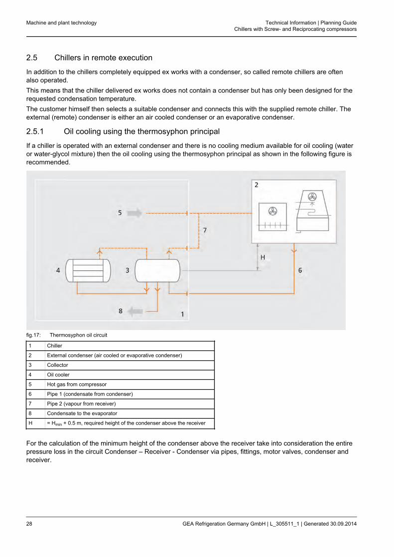
2.5.1 Oil cooling using the thermosyphon principal
If a chiller is operated with an external condenser and there is no cooling medium available for oil cooling (wateror water-glycol mixture) then the oil cooling using the thermosyphon principal as shown in the following figure isrecommended.
fig.17: Thermosyphon oil circuit
1 Chiller
2 External condenser (air cooled or evaporative condenser)
3 Collector
4 Oil cooler
5 Hot gas from compressor
6 Pipe 1 (condensate from condenser)
7 Pipe 2 (vapour from receiver)
8 Condensate to the evaporator
H = Hmin + 0.5 m, required height of the condenser above the receiver
For the calculation of the minimum height of the condenser above the receiver take into consideration the entirepressure loss in the circuit Condenser – Receiver - Condenser via pipes, fittings, motor valves, condenser andreceiver.
Machine and plant technology Technical Information | Planning GuideChillers with Screw- and Reciprocating compressors
28 GEA Refrigeration Germany GmbH | L_305511_1 | Generated 30.09.2014
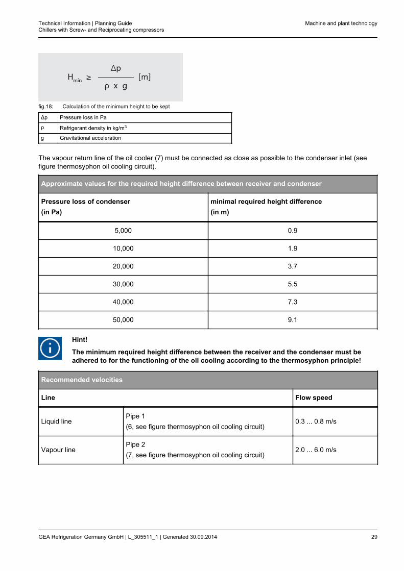
fig.18: Calculation of the minimum height to be kept
Δp Pressure loss in Pa
ρ Refrigerant density in kg/m3
g Gravitational acceleration
The vapour return line of the oil cooler (7) must be connected as close as possible to the condenser inlet (seefigure thermosyphon oil cooling circuit).
Approximate values for the required height difference between receiver and condenser
Pressure loss of condenser(in Pa)
minimal required height difference(in m)
5,000 0.9
10,000 1.9
20,000 3.7
30,000 5.5
40,000 7.3
50,000 9.1
Hint!
The minimum required height difference between the receiver and the condenser must beadhered to for the functioning of the oil cooling according to the thermosyphon principle!
Recommended velocities
Line Flow speed
Liquid linePipe 1(6, see figure thermosyphon oil cooling circuit)
0.3 ... 0.8 m/s
Vapour linePipe 2(7, see figure thermosyphon oil cooling circuit)
2.0 ... 6.0 m/s
Technical Information | Planning GuideChillers with Screw- and Reciprocating compressors
Machine and plant technology
GEA Refrigeration Germany GmbH | L_305511_1 | Generated 30.09.2014 29

Hint!
Additional fittings (valves) and longer pipework in lines 1 or 2 will increase the height differ-ence.The refrigerant vapour line, pipe 2 (7), needs to be constantly ascending above the inlet for thecondenser. No dead ends may be created!
Machine and plant technology Technical Information | Planning GuideChillers with Screw- and Reciprocating compressors
30 GEA Refrigeration Germany GmbH | L_305511_1 | Generated 30.09.2014
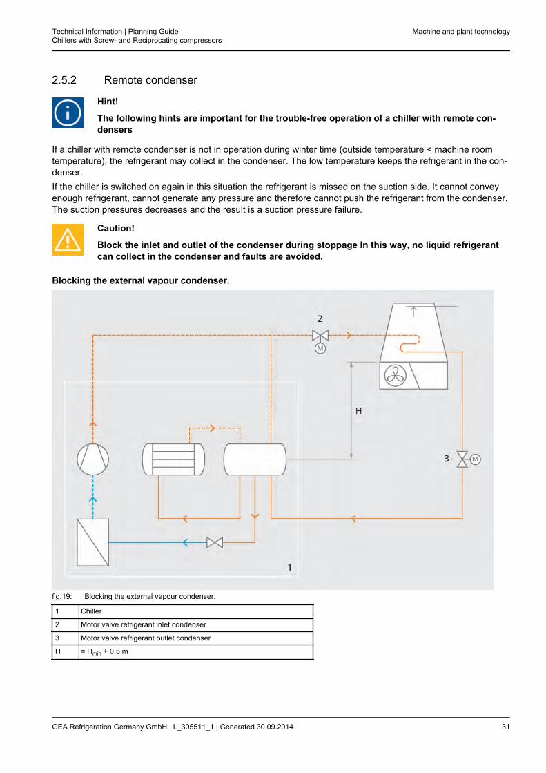
2.5.2 Remote condenser
Hint!
The following hints are important for the trouble-free operation of a chiller with remote con-densers
If a chiller with remote condenser is not in operation during winter time (outside temperature < machine roomtemperature), the refrigerant may collect in the condenser. The low temperature keeps the refrigerant in the con-denser.If the chiller is switched on again in this situation the refrigerant is missed on the suction side. It cannot conveyenough refrigerant, cannot generate any pressure and therefore cannot push the refrigerant from the condenser.The suction pressures decreases and the result is a suction pressure failure.
Caution!
Block the inlet and outlet of the condenser during stoppage In this way, no liquid refrigerantcan collect in the condenser and faults are avoided.
Blocking the external vapour condenser.
fig.19: Blocking the external vapour condenser.
1 Chiller
2 Motor valve refrigerant inlet condenser
3 Motor valve refrigerant outlet condenser
H = Hmin + 0.5 m
Technical Information | Planning GuideChillers with Screw- and Reciprocating compressors
Machine and plant technology
GEA Refrigeration Germany GmbH | L_305511_1 | Generated 30.09.2014 31
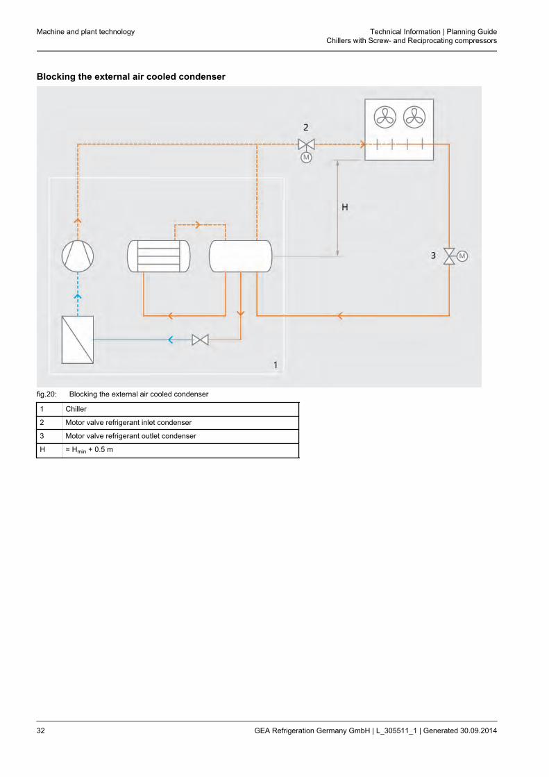
Blocking the external air cooled condenser
fig.20: Blocking the external air cooled condenser
1 Chiller
2 Motor valve refrigerant inlet condenser
3 Motor valve refrigerant outlet condenser
H = Hmin + 0.5 m
Machine and plant technology Technical Information | Planning GuideChillers with Screw- and Reciprocating compressors
32 GEA Refrigeration Germany GmbH | L_305511_1 | Generated 30.09.2014
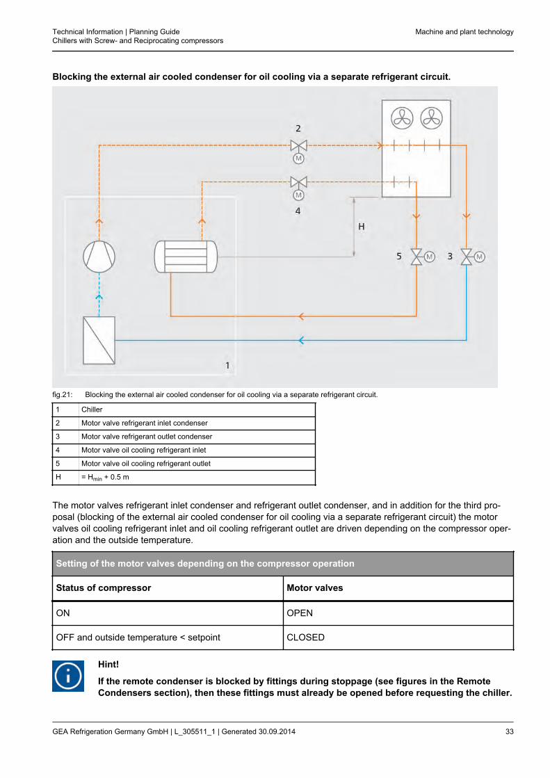
Blocking the external air cooled condenser for oil cooling via a separate refrigerant circuit.
fig.21: Blocking the external air cooled condenser for oil cooling via a separate refrigerant circuit.
1 Chiller
2 Motor valve refrigerant inlet condenser
3 Motor valve refrigerant outlet condenser
4 Motor valve oil cooling refrigerant inlet
5 Motor valve oil cooling refrigerant outlet
H = Hmin + 0.5 m
The motor valves refrigerant inlet condenser and refrigerant outlet condenser, and in addition for the third pro-posal (blocking of the external air cooled condenser for oil cooling via a separate refrigerant circuit) the motorvalves oil cooling refrigerant inlet and oil cooling refrigerant outlet are driven depending on the compressor oper-ation and the outside temperature.
Setting of the motor valves depending on the compressor operation
Status of compressor Motor valves
ON OPEN
OFF and outside temperature < setpoint CLOSED
Hint!
If the remote condenser is blocked by fittings during stoppage (see figures in the RemoteCondensers section), then these fittings must already be opened before requesting the chiller.
Technical Information | Planning GuideChillers with Screw- and Reciprocating compressors
Machine and plant technology
GEA Refrigeration Germany GmbH | L_305511_1 | Generated 30.09.2014 33
3 INSTALLATION
3.1 Machinery room (acc. to EN 378: Special Machinery Rooms)
Room only used for installation of the entire chiller or parts of the chiller. It is only accessible for maintenanceand repair of the chiller by authorized personnel [EN 378-1:2012-08; 3.2.2].
3.2 Installation areas
The installation areas of refrigerating systems are divided into three classes. Corresponding safety requirementsare placed upon these installation classes.
• Class APresence of persons of uncontrollable number (e.g. public buildings, hospitals, residential houses, theatres,supermarkets, schools, hotels etc.)
• Class BPresence of persons of limited number, some of them are acquainted with the special conditions and thegeneral safety requirements (e.g. office- and business buildings, laboratories, rooms for general manufactureand work)
• Class CRooms and buildings that only authorised personnel have access to (e.g. production buildings, cold stores,dairies, slaughterhouses, non-public areas in supermarkets) [EN 378-1:2012-08; 4.2.4]
Installation Technical Information | Planning GuideChillers with Screw- and Reciprocating compressors
34 GEA Refrigeration Germany GmbH | L_305511_1 | Generated 30.09.2014

3.3 Examples of machinery room arrangements
fig.22: Machinery room arrangement, example 1
fig.23: Machinery room arrangement, example 2
By providing an access to the machinery room exclusively from the outside (example 1) or a corridor (example2), a direct public access to the machinery room is prevented. When selecting one of these arrangements, allremaining sections of the building can be transformed into class C installation areas.
Technical Information | Planning GuideChillers with Screw- and Reciprocating compressors
Installation
GEA Refrigeration Germany GmbH | L_305511_1 | Generated 30.09.2014 35

3.4 Installation in buildings
fig.24: Installation on 1st basement floor
Installation on 1st basement floorBy separate access to the machinery room in thishotel (installation on 1st basement floor) the installa-tion is permitted in a class C area with unlimitedcharge. There are also no restrictions for basementfloors, if all remaining requirements on machineryrooms are observed.See also EN 378-1:2012-08; 3.2 and Appendix C aswell as EN 378-1:2012-08; 4.2.
fig.25: Installation on 2nd basement floor
Installation on 2nd basement floorThe machinery room has no separate access in thefigure "Installation on 2nd basement floor". Hence, theroom with access to the machinery room may be occu-pied solely by authorized instructed personnel inaccordance with installation area class C EN 378.
Installation Technical Information | Planning GuideChillers with Screw- and Reciprocating compressors
36 GEA Refrigeration Germany GmbH | L_305511_1 | Generated 30.09.2014

fig.26: Installation on upper floor
Installation on upper floorThe machinery room has a separate access via thestaircase and is only accessible to authorized person-nel. Hence, the installation in figure "Installation onupper floor" again complies with class C EN 378-1:2008-06 without restrictions concerning the charge.
Technical Information | Planning GuideChillers with Screw- and Reciprocating compressors
Installation
GEA Refrigeration Germany GmbH | L_305511_1 | Generated 30.09.2014 37

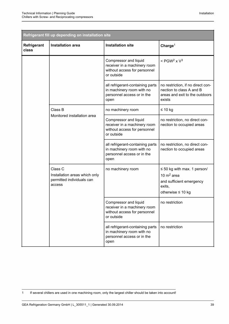
3.5 Refrigerant fill up depending on system installation site
[EN 378-1:2012-08; Appendix C]The evaporator of the chiller cools the cooling agent flowing through a closed circuit. It therefore has no directcontact with the chilled goods. The chiller is therefore always incorporated in an indirect circuit on the coolingagent side, according to EN 378-1:2012-08; 4.1.3.The following table is an excerpt from Table C.1 of 378-1:2012-08; Appendix C, the filling levels apply to the indi-rect circuit.
Refrigerant fill up depending on installation site
Refrigerantclass
Installation area Installation site Charge1
A1 Class AGeneral installation area
no machinery room < PGW2 x V3
Compressor and liquidreceiver in a machinery roomwithout access for personnelor outside
no restriction
all refrigerant-containing partsin machinery room with nopersonnel access or in theopen
no restriction
Class BMonitored installation areaandClass CInstallation areas which onlypermitted individuals canaccess
no machinery room In basement floors and upperfloors without sufficient emer-gency exits:.
< PGW2 x V3.Otherwise, no restriction.
Compressor and liquidreceiver in a machinery roomwithout access for personnelor outside
no restriction
all refrigerant-containing partsin machinery room with nopersonnel access or in theopen
no restriction
independent of installation site no restriction
B2 Class AGeneral installation area
no machinery room < PGW2 x V3
1 If several chillers are used in one machining room, only the largest chiller should be taken into account!2 PGW practical limitations [kg/m3], see EN 378-1:2012-08; Appendix F3 and Appendix E3 V: Room volume [m3]
Installation Technical Information | Planning GuideChillers with Screw- and Reciprocating compressors
38 GEA Refrigeration Germany GmbH | L_305511_1 | Generated 30.09.2014
Refrigerant fill up depending on installation site
Refrigerantclass
Installation area Installation site Charge1
Compressor and liquidreceiver in a machinery roomwithout access for personnelor outside
< PGW2 x V3
all refrigerant-containing partsin machinery room with nopersonnel access or in theopen
no restriction, if no direct con-nection to class A and Bareas and exit to the outdoorsexists
Class BMonitored installation area
no machinery room ≤ 10 kg
Compressor and liquidreceiver in a machinery roomwithout access for personnelor outside
no restriction, no direct con-nection to occupied areas
all refrigerant-containing partsin machinery room with nopersonnel access or in theopen
no restriction, no direct con-nection to occupied areas
Class CInstallation areas which onlypermitted individuals canaccess
no machinery room ≤ 50 kg with max. 1 person/
10 m2 areaand sufficient emergencyexits,otherwise ≤ 10 kg
Compressor and liquidreceiver in a machinery roomwithout access for personnelor outside
no restriction
all refrigerant-containing partsin machinery room with nopersonnel access or in theopen
no restriction
1 If several chillers are used in one machining room, only the largest chiller should be taken into account!
Technical Information | Planning GuideChillers with Screw- and Reciprocating compressors
Installation
GEA Refrigeration Germany GmbH | L_305511_1 | Generated 30.09.2014 39

3.6 Practical Limits for different refrigerants
The highest refrigerant concentration in an area where personnel are present, which do not require acute meas-ure for an escape are defined in accordance with EN 378-1:2012-08; Appendix F.3.1 as practical limit (kg refrig-erant / m³ room volume).
Practical Limits for different refrigerants
Refrigerant Refrigerant class Practical limit according to EN 378-1-1:2012-08Appendix tables E.1, E.2 and E.3
R134a A1 0,25 kg/m3
R404A A1 0,48 kg/m3
R407C A1 0,31 kg/m3
R410A A1 0,44 kg/m3
R507A A1 0,49 kg/m3
R717 B2 0,00035 kg/m3
Installation Technical Information | Planning GuideChillers with Screw- and Reciprocating compressors
40 GEA Refrigeration Germany GmbH | L_305511_1 | Generated 30.09.2014
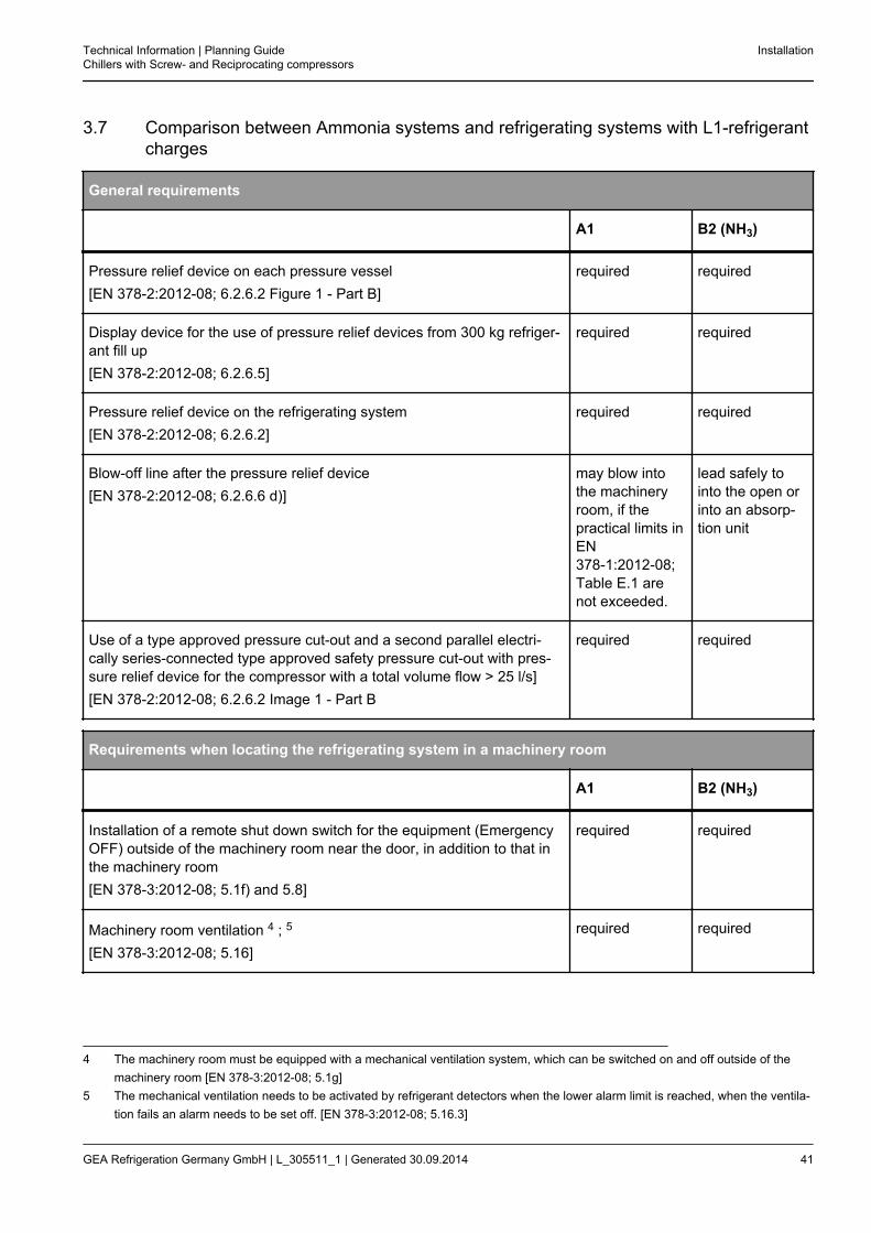
3.7 Comparison between Ammonia systems and refrigerating systems with L1-refrigerantcharges
General requirements
A1 B2 (NH3)
Pressure relief device on each pressure vessel[EN 378-2:2012-08; 6.2.6.2 Figure 1 - Part B]
required required
Display device for the use of pressure relief devices from 300 kg refriger-ant fill up[EN 378-2:2012-08; 6.2.6.5]
required required
Pressure relief device on the refrigerating system[EN 378-2:2012-08; 6.2.6.2]
required required
Blow-off line after the pressure relief device[EN 378-2:2012-08; 6.2.6.6 d)]
may blow intothe machineryroom, if thepractical limits inEN378-1:2012-08;Table E.1 arenot exceeded.
lead safely tointo the open orinto an absorp-tion unit
Use of a type approved pressure cut-out and a second parallel electri-cally series-connected type approved safety pressure cut-out with pres-sure relief device for the compressor with a total volume flow > 25 l/s][EN 378-2:2012-08; 6.2.6.2 Image 1 - Part B
required required
Requirements when locating the refrigerating system in a machinery room
A1 B2 (NH3)
Installation of a remote shut down switch for the equipment (EmergencyOFF) outside of the machinery room near the door, in addition to that inthe machinery room[EN 378-3:2012-08; 5.1f) and 5.8]
required required
Machinery room ventilation 4 ; 5
[EN 378-3:2012-08; 5.16]
required required
4 The machinery room must be equipped with a mechanical ventilation system, which can be switched on and off outside of themachinery room [EN 378-3:2012-08; 5.1g]
5 The mechanical ventilation needs to be activated by refrigerant detectors when the lower alarm limit is reached, when the ventila-tion fails an alarm needs to be set off. [EN 378-3:2012-08; 5.16.3]
Technical Information | Planning GuideChillers with Screw- and Reciprocating compressors
Installation
GEA Refrigeration Germany GmbH | L_305511_1 | Generated 30.09.2014 41
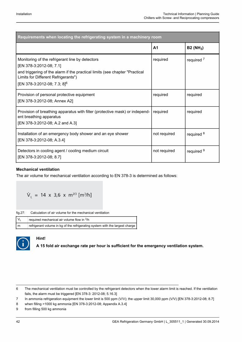
Requirements when locating the refrigerating system in a machinery room
A1 B2 (NH3)
Monitoring of the refrigerant line by detectors[EN 378-3:2012-08; 7.1]and triggering of the alarm if the practical limits (see chapter "PracticalLimits for Different Refrigerants")
[EN 378-3:2012-08; 7.3; 8]6
required required 7
Provision of personal protective equipment[EN 378-3:2012-08; Annex A2]
required required
Provision of breathing apparatus with filter (protective mask) or independ-ent breathing apparatus[EN 378-3:2012-08; A.2 and A.3]
required required
Installation of an emergency body shower and an eye shower[EN 378-3:2012-08; A.3.4]
not required required 8
Detectors in cooling agent / cooling medium circuit[EN 378-3:2012-08; 8.7]
not required required 9
Mechanical ventilationThe air volume for mechanical ventilation according to EN 378-3 is determined as follows:
fig.27: Calculation of air volume for the mechanical ventilation
VL required mechanical air volume flow in 3/h
m refrigerant volume in kg of the refrigerating system with the largest charge
Hint!
A 15 fold air exchange rate per hour is sufficient for the emergency ventilation system.
6 The mechanical ventilation must be controlled by the refrigerant detectors when the lower alarm limit is reached. If the ventilationfails, the alarm must be triggered [EN 378-3: 2012-08; 5.16.3]
7 In ammonia refrigeration equipment the lower limit is 500 ppm (V/V); the upper limit 30,000 ppm (V/V) [EN 378-3:2012-08; 8.7]8 when filling >1000 kg ammonia [EN 378-3:2012-08; Appendix A.3.4]9 from filling 500 kg ammonia
Installation Technical Information | Planning GuideChillers with Screw- and Reciprocating compressors
42 GEA Refrigeration Germany GmbH | L_305511_1 | Generated 30.09.2014

Caution!
As the gas in the refrigerants R134A, R407C and R134A is heavier than air, a minimum of 50%of the air to be dissipated must be taken from the lowest point of the machinery room. In thecase of ammonia refrigerating systems the suction of the machinery room must be above, i.e.under the ceiling as the escaping ammonia gas is lighter than air.
Required air exchange for the removal of waste heatThe heat emission of the warm components of a chiller, such as pressure side compressors and oil separatorsand the power dissipation recorded from the electric motor, must be removed with the machining room ventila-tion. 9% of the installed engine capacity is to be used as the variable for the heat quantity to be removed.
fig.28: Calculation of air volume for removal of waste heat
VW required air volume for waste heat to be removed
QA 0.09 * P installed, the waste heat, 9% engine capacity in W
ρ Air density in kg/m3
Cp specific heat capacity of the air in kJ/kg K
Δt Difference of maximum machinery room temperature minus maximum ambient air in K
Example for calculating the required air exchange rate in machinery rooms:
Refrigeratingcapacity*
required enginecapacity*
Waste heat to beremoved
Refrigerant fill up
kW kW kW kg
FX PP 1500 1540 285 26 190
BluAstrum1000 1120 210 19 125
FX GC PP 600 820 140 13 70
* for cooling agent temperatures of 12/6 °C // for cooling medium temperatures of 30/35 °C
Comparison of the calculated air volumes
Air volume VL mechanical ventilation(EN 378-3) according to refrigerant fillup
Air volume VW to remove waste heat
Calculation according to the above formulae
FX PP 1500 1666 7077
Technical Information | Planning GuideChillers with Screw- and Reciprocating compressors
Installation
GEA Refrigeration Germany GmbH | L_305511_1 | Generated 30.09.2014 43

Comparison of the calculated air volumes
Air volume VL mechanical ventilation(EN 378-3) according to refrigerant fillup
Air volume VW to remove waste heat
BluAstrum1000 1260 5215
FX GC PP 600 856 3477
** Delta t = 10 K
Hint!
The results of the table show that the required air flow volume to remove the waste heat of thechiller is significantly larger that the value calculated in relation to the refrigerant fill upaccording to EN 378-3!
Installation Technical Information | Planning GuideChillers with Screw- and Reciprocating compressors
44 GEA Refrigeration Germany GmbH | L_305511_1 | Generated 30.09.2014

3.8 Airborne and structure-borne sound
Technical sound fundamentalsSound represents the distribution of the smallest pressure and density variations in an elastic medium (gas, liq-uid, solids).The noise, the sound, the tone of how people and also animals perceive something is described generally assound. Physically, sound is a wave-formed unfolding oscillation.A mechanical force on a solid causes an oscillation which is directly passed on to the environment. The propaga-tion speed is dependent on a sound-carrying medium and the temperature.You can differentiate between airborne sound and structure-borne sound.
• Airborne sound:The air is compressed and expanded alternately by the oscillation from the sound source.
• Structure-borne sound:Tangible vibrations of the sound source are described as structure-borne sound.
Definitions
• Sound distributionIn principle, the sound spreads in all directions equally from an undirected source. If you think of a point-likesound source, this radiates its energy in a spherical form in all direction equally and continuously. The largerthe distance to the sound source the greater the sound decay is. Every doubling of the distance to the soundsource reduces the sound pressure level by 6 dB. Reflective surfaces reduce the emission surface area.This results in hemispherical or quarter-spherical radiation, for example. The smaller the radiating surfacethe smaller the depletion of the sound level.Larger, cuboid-shaped machines e.g. refrigerating machines, condensers or heat exchangers have irregularradiation behaviour and therefore no equal sound field at close range. Measurement at close range is there-fore too imprecise, only in the far field (approx. 2 times the largest device measurement) does such a soundsource approach a point-like source.
Technical Information | Planning GuideChillers with Screw- and Reciprocating compressors
Installation
GEA Refrigeration Germany GmbH | L_305511_1 | Generated 30.09.2014 45

fig.29: Sound distribution
X Distance in m
Y Sound pressure level depletion in dB
A Without reflection
B With some reflection
• Sound pressureThe pressure oscillations of the sound wave spreading in the air in the carrier medium are called sound pres-sure. Influencing factors such as installation site, absorption of the environment and distance of the measur-ing point to the sound source lead to different indications of the associated measurable pressure in Pa (Pas-cal).
• Sound pressure levelThe sound pressure level describes the sound pressure at a certain place depending on the distance to thesound source and the environmental factors of the sound field.It is the log10 of the ratio of the effect value squared of the sound pressure p to the square of the referencevalue po.
The reference value po was determined as 20 Pa at the beginning of the 20th century. The sound pressurelevel is indicated in dB (decibel).An evaluation of human hearing sensitivity does not take place in the process. Humans have a limited hear-ing range of approx. 14 Hz to 20 kHz. In this range frequencies are perceived at different levels of loudness.In order to take account of this sensitivity, the spectrum of the sound pressure level is evaluated.
• Sound emissionsTransmission of sound from a sound source. In the case of forecasting sound emissions the sound pressurelevel of the sound emissions is determined in a predetermined distance to the sound source according topredetermined models. The measured value based on the "source strength" and independent of distance isthe acoustic level Lwa.
• Sound immissionsThe effect of the sound pressure available at this location is described with the term sound immission. Soundimmission is dependent on the sound emission and the sound distribution. The sound immission level isused for the quantitative description of the sound immission as part of noise protection.
Installation Technical Information | Planning GuideChillers with Screw- and Reciprocating compressors
46 GEA Refrigeration Germany GmbH | L_305511_1 | Generated 30.09.2014

The first general administrative regulation on the Federal Immission Control Act (TA Lärm) gives a goodoverview of the requirements on sound immissions and also cites other associated standards and guide-lines:
– German Technical Guidelines for noise reduction [new version]
– The sixth general administrative regulation on the Federal Immission Control Act (TA Lärm) of 26 August1998.
Immission guide values for immission location outside of buildings
Immission guide values for the rating level Day 6:00 - 22:00 Night 22:00 - 06:00
In industrial areas only with commercial or industrial plant 70 dB(A) 70 dB(A)
In commercial areas with predominantly commercial plant 65 dB(A) 50 dB(A)
In central areas, villages and mixed areas with commercialplant and residences 60 dB(A) 45 dB(A)
In general residential areas and small settlement areas withpredominantly residences 55 dB(A) 40 dB(A)
In just residential areas with exclusively residences 50 dB(A) 35 dB(A)
In spa areas, for hospitals and nursing homes 45 dB(A) 35 dB(A)
Noise reduction is therefore possible in many ways but often requires higher investment costs. This shouldalready be considered at the cost planning.
Hint!
At the system planning, the inclusion of an acoustician is recommended in all cases. Soundimmissions should not be underestimated in their effect, particularly as they are also subjectto legal regulations.
• Acoustic levelThe acoustic level of a sound source is an acoustic parameter. It describes the sound energy given out by asound source per time unit (1 s). It is therefore an energy parameter. The unit is Watt (W). The associatedlogarithmic parameter is the acoustic capacity, which is indicated in dB (decibel). The acoustic leveldescribes the source strength of a sound producer and not the sound field. It is therefore an importantenergy parameter to evaluate a sound source as the acoustic level is independent from the location of thesource or the receiver. It cannot be directly measured.
• Spectral evaluationTo evaluate a measured sound pressure the sensitivity of humans is included.Empirically determined values are calculated with actual measuring levels. Not only the frequency but alsothe wave lengths are important for the determination of the loudness experienced and the calculation ofnoise reduction measures.
Technical Information | Planning GuideChillers with Screw- and Reciprocating compressors
Installation
GEA Refrigeration Germany GmbH | L_305511_1 | Generated 30.09.2014 47

Spectral evaluation
Octave centre frequencies / (Hz)
Acoustic level / (dB)
63 125 250 500 1 k 2 k 4 k 8 k Lw-lin10 Lw(A)11
Measurement 70.1 74.5 72.6 69.4 66.3 62.4 57.9 45.1 78.6 -
A evaluation -26.2 -16.1 -8.6 -3.2 0 1.2 -1.0 -1.1 - -
Evaluationspectrum 43.9 58.4 64 66.2 66.3 63.6 56.9 44 - 71.6
10 Lw-lin = linearly measured acoustic capacity11 Lw-(A) = acoustic capacity according to A evaluation
Installation Technical Information | Planning GuideChillers with Screw- and Reciprocating compressors
48 GEA Refrigeration Germany GmbH | L_305511_1 | Generated 30.09.2014

3.9 Chillers using ammonia as a cooling medium.
In principle, in the case of damage to evaporators/ condensers (e.g. plate penetration) there is the danger of mix-ing of media.It may cause ammonia to flow to the liquid side of the heat exchanger.
Caution!
It creates the danger of mixing of media.
To prevent subsequent damage to the hydraulic system, measures need to be taken on the building side. Thesemay take the form of:
1. NH3-sensors in the pipe system close behind the heat exchangers.
Ammonia sensors need to be installed in the piping system near the outlet from the heat exchanger/evapora-tor, which will detect the presence of ammonia in the cooling agent solution.
2. Separator heat exchangersin glycol systems with copper piping.Should a copper heat exchanger be installed in the cooling agent circuit and the chiller operate using ammo-nia as the cooling medium, then a double indirect system can be installed (see also EN 378-1:2012; 4.4.2.4).This means that an additional heat exchanger is to be installed between the cooling agent flowing to thechiller and the cooling agent consumer circuit to assure hydraulic decoupling.Only then will it be possible to prevent the cooling agent from entering the cooling agent consumer circuitand prevent any subsequent damage in the event of leakage in the condenser/heat exchanger in the chiller.
Technical Information | Planning GuideChillers with Screw- and Reciprocating compressors
Installation
GEA Refrigeration Germany GmbH | L_305511_1 | Generated 30.09.2014 49

4 REQUIREMENTS OF HYDRAULIC CIRCUITS
The following hints on the design of hydraulic circuits in connection with GEA Grasso chillers are very importantfor the fault-free functioning of a chiller. All hints for heat exchangers and the measurements of system compo-nents (e.g. buffer storage) are based on practical experiences and should always be observed. The hydrauliccircuit is usually not in the scope of supply of the manufacturer. Certain hints e.g. for filters before heat exchang-ers, water quality or temperature gradients are however also part of the operating manuals of GEA Grasso chill-ers.
4.1 Requirements for the hydraulic circuit
The use of plate heat exchangers as evaporators or condensers requires unpolluted cooling agents and coolingmedia.In the cooling agent circuit (evaporator) closed systems are always selected as standard. The cooling agentmust be free from particles >0.9 mm on entry into the heat exchanger.To guarantee this media quality even under unfavourable conditions, an appropriate filter must also be installedon site at the inlet to the heat exchanger.The mesh for such a filter needs to be ≤ 0.9 mm.Should the chiller need to remain in operation during filter cleaning, double filters need to be used. Pressure lossthrough the filter needs to be taken into consideration on site when configuring the pump.
Requirements of hydraulic circuits Technical Information | Planning GuideChillers with Screw- and Reciprocating compressors
50 GEA Refrigeration Germany GmbH | L_305511_1 | Generated 30.09.2014

4.2 Application: Chiller in the consumer circuit
fig.30: Hydraulic circuit with dual circuit buffer tank
1.1 Chiller
2.1 Primary circuit cooling agent pump
3.1 filter
4.1 Check valve (primary circuit cooling agent pump); only required if more than one chiller is available on the production side.
5 Dual circuit buffer storage (hydraulic separator)
6 Safety valve cooling agent circuit
7 Compensating ring cooling agent circuit
8 Automatic venting cooling agent circuit
9 Filling valve cooling agent circuit
10 Secondary circuit cooling agent pump
11 Consuming devices
12 Controller
Requirements for the hydraulic circuit
• A reservoir is installed between the generator and consumer (double-pipe connection). Circuit correspondsto diagram.
• The hydraulic separator is to be designed in such a way that it can take on the function of a buffer storage/stratified storage tank. The tank volume is determined as follows:
Technical Information | Planning GuideChillers with Screw- and Reciprocating compressors
Requirements of hydraulic circuits
GEA Refrigeration Germany GmbH | L_305511_1 | Generated 30.09.2014 51
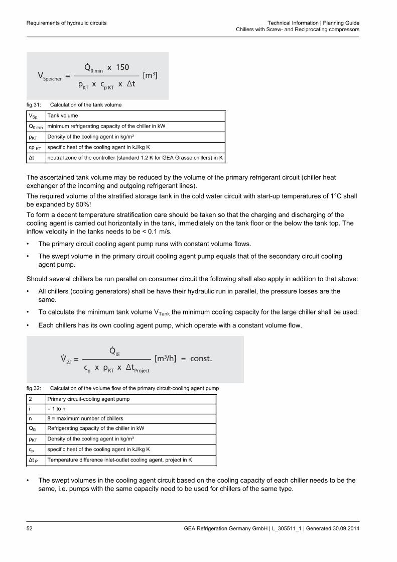
fig.31: Calculation of the tank volume
VSp. Tank volume
Q0 min minimum refrigerating capacity of the chiller in kW
ρKT Density of the cooling agent in kg/m³
cp KT specific heat of the cooling agent in kJ/kg K
Δt neutral zone of the controller (standard 1.2 K for GEA Grasso chillers) in K
The ascertained tank volume may be reduced by the volume of the primary refrigerant circuit (chiller heatexchanger of the incoming and outgoing refrigerant lines).The required volume of the stratified storage tank in the cold water circuit with start-up temperatures of 1°C shallbe expanded by 50%!To form a decent temperature stratification care should be taken so that the charging and discharging of thecooling agent is carried out horizontally in the tank, immediately on the tank floor or the below the tank top. Theinflow velocity in the tanks needs to be < 0.1 m/s.
• The primary circuit cooling agent pump runs with constant volume flows.
• The swept volume in the primary circuit cooling agent pump equals that of the secondary circuit coolingagent pump.
Should several chillers be run parallel on consumer circuit the following shall also apply in addition to that above:
• All chillers (cooling generators) shall be have their hydraulic run in parallel, the pressure losses are thesame.
• To calculate the minimum tank volume VTank the minimum cooling capacity for the large chiller shall be used:
• Each chillers has its own cooling agent pump, which operate with a constant volume flow.
fig.32: Calculation of the volume flow of the primary circuit-cooling agent pump
2 Primary circuit-cooling agent pump
i = 1 to n
n 8 = maximum number of chillers
Q0i Refrigerating capacity of the chiller in kW
ρKT Density of the cooling agent in kg/m³
cp specific heat of the cooling agent in kJ/kg K
Δt P Temperature difference inlet-outlet cooling agent, project in K
• The swept volumes in the cooling agent circuit based on the cooling capacity of each chiller needs to be thesame, i.e. pumps with the same capacity need to be used for chillers of the same type.
Requirements of hydraulic circuits Technical Information | Planning GuideChillers with Screw- and Reciprocating compressors
52 GEA Refrigeration Germany GmbH | L_305511_1 | Generated 30.09.2014

• The total volume flow of the consumer circuit is smaller or equal to the total of the volume flows of all genera-tor circuits.
fig.33: Calculation of the total volume flow of the consumer circuit
V10 Total swept volume consumer circuit
V2i Total volume flow generator circuits
It should be ensured on site that unpolluted refrigerant flows through the evaporator. The refrigerant must befree from particles >0.9 mm on entry into the evaporator. To guarantee this media quality the appropriatefilter needs to be installed on site.The mesh for such a filter needs to be ≤ 0.9 mm!Should the chiller need to remain in operation during filter cleaning, double filters need to be used.Pressure loss through the filter needs to be taken into consideration on site when configuring the pump.In addition to inspection for mechanical contamination the cooling agent needs to be specifically examinedfor chloride. Depending on the plate material the chloride levels in the "Requirements for water quality, limits"chapter can be tolerated.
Hint!
There is the possibility of back-condensation of the suction gas in the suction lineIf the ascertained required tank volume is not realised, sudden performance requirements inthe suction line of the compressor corresponding to the increase in suction pressure will leadto an increase in suction gas temperature. Due to the condensation heat of the refrigerant, thepipe wall will be heated to the increased suction gas temperature. The suction gas will con-dense on the pipe wall. The compressor then sucks the liquid in! The sudden increase in pres-sure on the suction side is monitored with the compressor control. If the suction pressureincreases to more than 3 K in 120 s, a fault shut-down occurs in order to protect the compres-sor.
Technical Information | Planning GuideChillers with Screw- and Reciprocating compressors
Requirements of hydraulic circuits
GEA Refrigeration Germany GmbH | L_305511_1 | Generated 30.09.2014 53

4.3 Application instruction for the installation of the flow switch and temperature sensorfor the cooling agent outlet temperature
The temperature sensors for measuring the cooling agent outlet temperature and optionally for the cooling agentinlet temperature as well as the flow switch and welded sleeve are included in the delivery as separately sup-plied parts and should be installed in the pipework by the plant engineer.The flow switch can only be installed in a horizontal pipe, or a vertical pipe with a flow running in an upwarddirection. The flow switch must be installed in a distance of 5 to 10 times of pipe diameter behind the previouslyflowed curve or valve. The outlet run must equal 3 to 5 times the pipe diameter.If an electronic flow sensor is installed in a horizontal pipe, this must be carried out laterally. In the case of instal-lation from above, the pipe to be monitored must be completely filled. In the case of installation from below, con-taminant deposits will falsify the measurement.Between the cooling agent outlet from the evaporator/ liquid separator and the temperature sensor, you shouldprovide at least 2 m of pipe and two 90-degree directional changes by pipe elbows or fittings. If the temperaturesensor is installed directly downstream of the flow switch, a distance of 5 to 10 times the pipe diameter must alsobe kept here.The cabling of the temperature sensor and flow switch must be carried out with an additional cable length of 6 mmeasured from the outlet point of the evaporator/ liquid separator.
fig.34: Cooling agent system
1 Resistance thermometer - cooling agent inlet temperature
2 Evaporator/liquid separator
3 Flow switch
4 Resistance thermometer - cooling agent outlet temperature
Requirements of hydraulic circuits Technical Information | Planning GuideChillers with Screw- and Reciprocating compressors
54 GEA Refrigeration Germany GmbH | L_305511_1 | Generated 30.09.2014
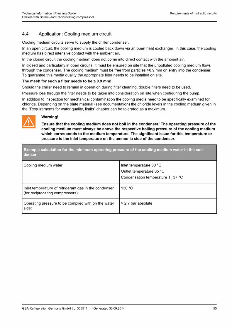
4.4 Application: Cooling medium circuit
Cooling medium circuits serve to supply the chiller condenser.In an open circuit, the cooling medium is cooled back down via an open heat exchanger. In this case, the coolingmedium has direct intensive contact with the ambient air.In the closed circuit the cooling medium does not come into direct contact with the ambient air.In closed and particularly in open circuits, it must be ensured on site that the unpolluted cooling medium flowsthrough the condenser. The cooling medium must be free from particles >0.9 mm on entry into the condenser.To guarantee this media quality the appropriate filter needs to be installed on site.The mesh for such a filter needs to be ≤ 0.9 mm!Should the chiller need to remain in operation during filter cleaning, double filters need to be used.Pressure loss through the filter needs to be taken into consideration on site when configuring the pump.In addition to inspection for mechanical contamination the cooling media need to be specifically examined forchloride. Depending on the plate material (see documentation) the chloride levels in the cooling medium given inthe "Requirements for water quality, limits" chapter can be tolerated as a maximum.
Warning!
Ensure that the cooling medium does not boil in the condenser! The operating pressure of thecooling medium must always be above the respective boiling pressure of the cooling mediumwhich corresponds to the medium temperature. The significant issue for this temperature orpressure is the inlet temperature on the ammonia side of the condenser.
Example calculation for the minimum operating pressure of the cooling medium water in the con-denser
Cooling medium water: Inlet temperature 30 °COutlet temperature 35 °CCondensation temperature Tc 37 °C
Inlet temperature of refrigerant gas in the condenser(for reciprocating compressors):
130 °C
Operating pressure to be complied with on the waterside:
> 2.7 bar absolute
Technical Information | Planning GuideChillers with Screw- and Reciprocating compressors
Requirements of hydraulic circuits
GEA Refrigeration Germany GmbH | L_305511_1 | Generated 30.09.2014 55
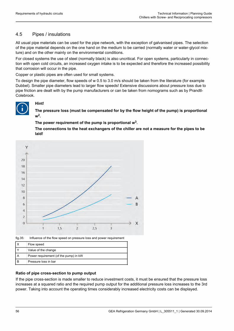
4.5 Pipes / insulations
All usual pipe materials can be used for the pipe network, with the exception of galvanised pipes. The selectionof the pipe material depends on the one hand on the medium to be carried (normally water or water-glycol mix-ture) and on the other mainly on the environmental conditions.For closed systems the use of steel (normally black) is also uncritical. For open systems, particularly in connec-tion with open cold circuits, an increased oxygen intake is to be expected and therefore the increased possibilitythat corrosion will occur in the pipe.Copper or plastic pipes are often used for small systems.To design the pipe diameter, flow speeds of w 0.5 to 3.0 m/s should be taken from the literature (for exampleDubbel). Smaller pipe diameters lead to larger flow speeds! Extensive discussions about pressure loss due topipe friction are dealt with by the pump manufacturers or can be taken from nomograms such as by Prandtl-Colebrook.
Hint!
The pressure loss (must be compensated for by the flow height of the pump) is proportionalw2.The power requirement of the pump is proportional w3.The connections to the heat exchangers of the chiller are not a measure for the pipes to belaid!
fig.35: Influence of the flow speed on pressure loss and power requirement
X Flow speed
Y Value of the change
A Power requirement (of the pump) in kW
B Pressure loss in bar
Ratio of pipe cross-section to pump outputIf the pipe cross-section is made smaller to reduce investment costs, it must be ensured that the pressure lossincreases at a squared ratio and the required pump output for the additional pressure loss increases to the 3rdpower. Taking into account the operating times considerably increased electricity costs can be displayed.
Requirements of hydraulic circuits Technical Information | Planning GuideChillers with Screw- and Reciprocating compressors
56 GEA Refrigeration Germany GmbH | L_305511_1 | Generated 30.09.2014
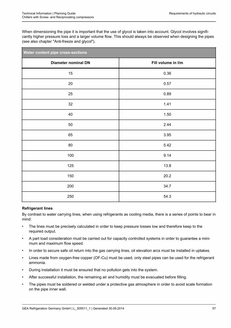
When dimensioning the pipe it is important that the use of glycol is taken into account. Glycol involves signifi-cantly higher pressure loss and a larger volume flow. This should always be observed when designing the pipes(see also chapter "Anti-freeze and glycol").
Water content pipe cross-sections
Diameter nominal DN Fill volume in l/m
15 0.36
20 0.57
25 0.89
32 1.41
40 1.50
50 2.44
65 3.95
80 5.42
100 9.14
125 13.8
150 20.2
200 34.7
250 54.3
Refrigerant linesBy contrast to water carrying lines, when using refrigerants as cooling media, there is a series of points to bear inmind:
• The lines must be precisely calculated in order to keep pressure losses low and therefore keep to therequired output.
• A part load consideration must be carried out for capacity controlled systems in order to guarantee a mini-mum and maximum flow speed.
• In order to secure safe oil return into the gas carrying lines, oil elevation arcs must be installed in uptakes.
• Lines made from oxygen-free copper (OF-Cu) must be used, only steel pipes can be used for the refrigerantammonia.
• During installation it must be ensured that no pollution gets into the system.
• After successful installation, the remaining air and humidity must be evacuated before filling.
• The pipes must be soldered or welded under a protective gas atmosphere in order to avoid scale formationon the pipe inner wall.
Technical Information | Planning GuideChillers with Screw- and Reciprocating compressors
Requirements of hydraulic circuits
GEA Refrigeration Germany GmbH | L_305511_1 | Generated 30.09.2014 57

InsulationThe insulation used depends on the media temperature and the condition of the surrounding air. Even in climatetechnology, a professionally processed, diffusion-proof insulation should be ensured. Due to condensation for-mation there can be moisture damage in rooms. Today, a series of well-known manufacturers offer UV-resistantinsulations for outside.
Requirements of hydraulic circuits Technical Information | Planning GuideChillers with Screw- and Reciprocating compressors
58 GEA Refrigeration Germany GmbH | L_305511_1 | Generated 30.09.2014
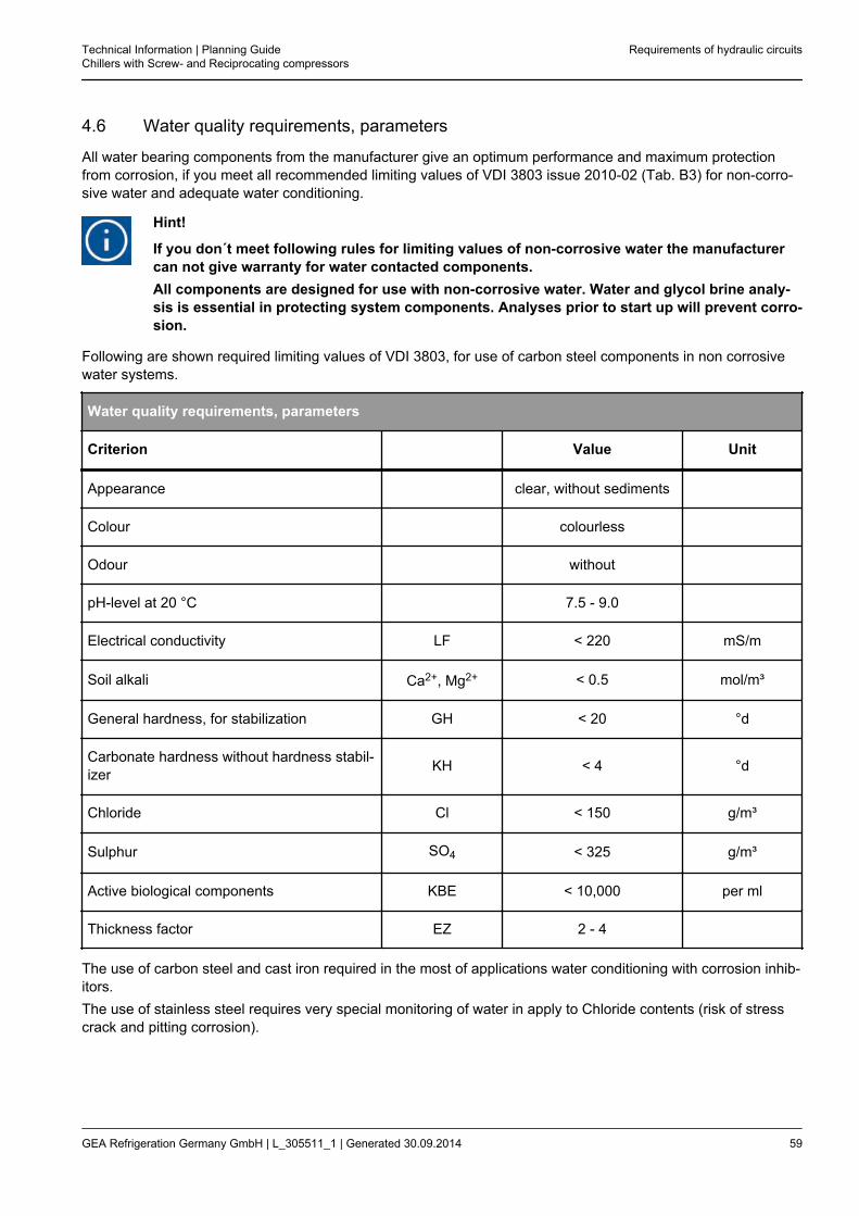
4.6 Water quality requirements, parameters
All water bearing components from the manufacturer give an optimum performance and maximum protectionfrom corrosion, if you meet all recommended limiting values of VDI 3803 issue 2010-02 (Tab. B3) for non-corro-sive water and adequate water conditioning.
Hint!
If you don´t meet following rules for limiting values of non-corrosive water the manufacturercan not give warranty for water contacted components.All components are designed for use with non-corrosive water. Water and glycol brine analy-sis is essential in protecting system components. Analyses prior to start up will prevent corro-sion.
Following are shown required limiting values of VDI 3803, for use of carbon steel components in non corrosivewater systems.
Water quality requirements, parameters
Criterion Value Unit
Appearance clear, without sediments
Colour colourless
Odour without
pH-level at 20 °C 7.5 - 9.0
Electrical conductivity LF < 220 mS/m
Soil alkali Ca2+, Mg2+ < 0.5 mol/m³
General hardness, for stabilization GH < 20 °d
Carbonate hardness without hardness stabil-izer KH < 4 °d
Chloride Cl < 150 g/m³
Sulphur SO4 < 325 g/m³
Active biological components KBE < 10,000 per ml
Thickness factor EZ 2 - 4
The use of carbon steel and cast iron required in the most of applications water conditioning with corrosion inhib-itors.The use of stainless steel requires very special monitoring of water in apply to Chloride contents (risk of stresscrack and pitting corrosion).
Technical Information | Planning GuideChillers with Screw- and Reciprocating compressors
Requirements of hydraulic circuits
GEA Refrigeration Germany GmbH | L_305511_1 | Generated 30.09.2014 59

Hint!
Recommend for use of plate heat exchangers in refrigerant circuit< 100 ppm Cl while using steel 1.4301 andmaximum 40 °C wall temperature in the plate heat exchanger< 200 ppm Cl while using steel 1.4401 andmaximum 100 °C wall temperature in the plate heat exchanger
fig.36: Corrosion resistance in presence of chlorides
X Chloride ion concentration in ppm Cl-
Y Wall temperature heat exchanger in °C
A AISI 304
B AISI 316
C SMO 254
Hint!
Manufacturer recommendation: Use uncontaminated cooling agents and cooling media, inparticular in chillers and the use of plate heat exchangers.The media quality needs to be assured through an appropriate filter on the inlet to the heatexchanger. The mesh for such a filter needs to be ≤ 0.9 mm!Should the chiller need to remain in operation during filter cleaning, double filters need to beused. Pressure loss through the filter need to be taken into consideration on the building sidewhen configuring the pump.
The manufacturer recommends enlisting the services of a reputable water conditioning company.
Requirements of hydraulic circuits Technical Information | Planning GuideChillers with Screw- and Reciprocating compressors
60 GEA Refrigeration Germany GmbH | L_305511_1 | Generated 30.09.2014
4.7 Use of filters
Caution!
To protect the heat exchanger (evaporator/condenser), the chillers with water cooled con-denser filters need to use a dirt filter with a mesh no greater than ≤0.9mm in the cooling agentcircuit.Installations without dirt filters may impair the orderly function of the chiller and in additioncause significant damage to the equipment. Such damage is not covered by the manufactur-er's guarantee.
Technical Information | Planning GuideChillers with Screw- and Reciprocating compressors
Requirements of hydraulic circuits
GEA Refrigeration Germany GmbH | L_305511_1 | Generated 30.09.2014 61

5 ELECTRICS REQUIREMENTS
5.1 Network systems
Different forms of networks are available for the energy supply of electric drives.The designation of network systems takes place according to IEC 60364-1 (DIN VDE 0100-100).The network system of the power supply determined which protective devices are required.The network systems primarily differ in that whether the star point of the supply transformer is earthed, the earth(PE) is separate or is together with the neutral (N) as a neutral/earth line (PEN).There are the following network systems:
• TN-S system
• TN-C system
• TT system
• IT system
Explanation of the abbreviations used
First letterEarthing conditions of the supplying power source
TDirect earthing of a point(e.g. star point of a transformer)
I Insulation of all active parts or connection of apoint with the earth via an impedance
Second letterEarthing conditions of the bodies of the electricalsystem
N Bodies directly connected to the signal ground
T Bodies directly connected to the ground
Other lettersArrangement of the neutral and earth
C Neutral and earth are combined in a line (PEN)
SNeutral and earth are separated(separate)
Derivation as abbreviation
N Neutral Neutral wire
PE Protection-Earth Earth wire
PEN Protection-Earth-Neutral Neutral/ earth
T Terre Earth
I Insulation Insulation
S Separated neutral and protection earth Neutral and protection earth separated
C Combined neutral and protection earth Neutral and protection earth combined in one line
Electrics requirements Technical Information | Planning GuideChillers with Screw- and Reciprocating compressors
62 GEA Refrigeration Germany GmbH | L_305511_1 | Generated 30.09.2014
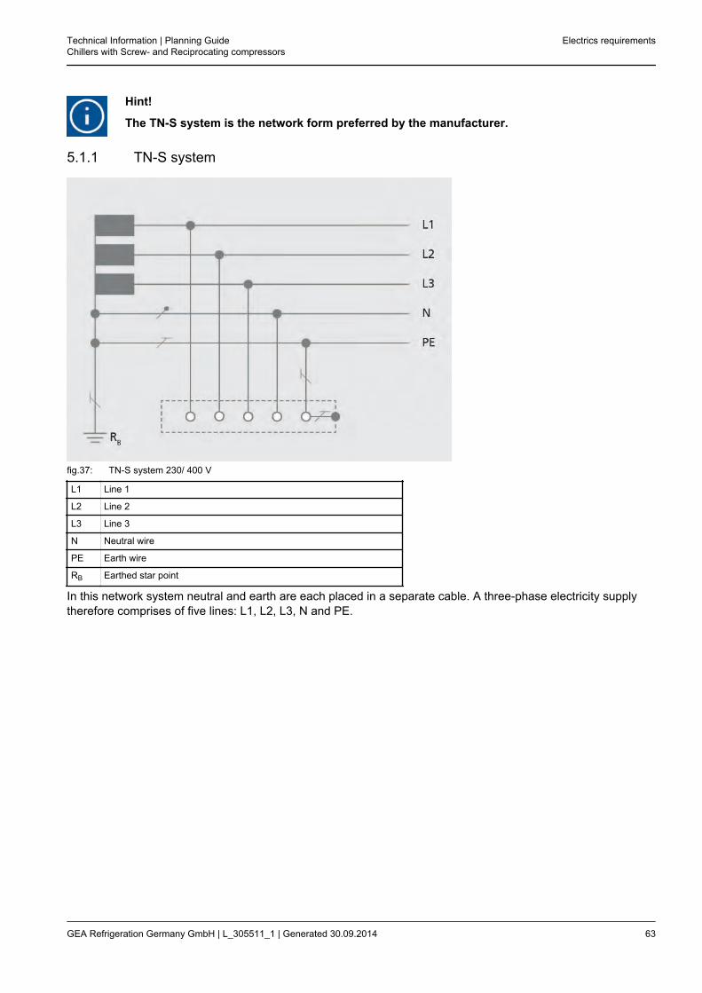
Hint!
The TN-S system is the network form preferred by the manufacturer.
5.1.1 TN-S system
fig.37: TN-S system 230/ 400 V
L1 Line 1
L2 Line 2
L3 Line 3
N Neutral wire
PE Earth wire
RB Earthed star point
In this network system neutral and earth are each placed in a separate cable. A three-phase electricity supplytherefore comprises of five lines: L1, L2, L3, N and PE.
Technical Information | Planning GuideChillers with Screw- and Reciprocating compressors
Electrics requirements
GEA Refrigeration Germany GmbH | L_305511_1 | Generated 30.09.2014 63
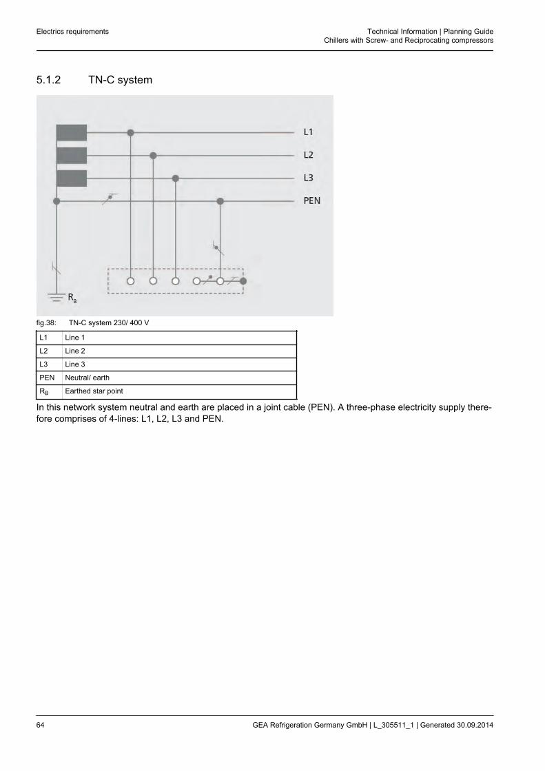
5.1.2 TN-C system
fig.38: TN-C system 230/ 400 V
L1 Line 1
L2 Line 2
L3 Line 3
PEN Neutral/ earth
RB Earthed star point
In this network system neutral and earth are placed in a joint cable (PEN). A three-phase electricity supply there-fore comprises of 4-lines: L1, L2, L3 and PEN.
Electrics requirements Technical Information | Planning GuideChillers with Screw- and Reciprocating compressors
64 GEA Refrigeration Germany GmbH | L_305511_1 | Generated 30.09.2014

5.1.3 TN-C-S system
fig.39: TN-C-S system 230/ 400 V
L1 Line 1
L2 Line 2
L3 Line 3
PE Earth wire
N Neutral wire
RB Earthed star point
In practice, it often happens that network systems change within a system.
Caution!
When the PEN line has been divided into PE and N once, these may not be put back togetheragain.
Example:Transformation of a TN-C system into a TN-S system. In this case the PEN line is divided into a separate PE lineand an N line.From a 4-line TN-C system (L1, L2, L3, PEN) therefore becomes a 5-line TN-S system (L1, L2, L3, N, PE).
Technical Information | Planning GuideChillers with Screw- and Reciprocating compressors
Electrics requirements
GEA Refrigeration Germany GmbH | L_305511_1 | Generated 30.09.2014 65

5.1.4 TT system
fig.40: TT system 230/ 400 V
L1 Line 1
L2 Line 2
L3 Line 3
N Neutral wire
PE Earth wire
RB Earthed star point
RA Local earth
In this network system a point, in general the star point of the transformer, is directly earthed (signal ground).The earthed point is led into the system as an N line in most cases. The bodies of the electric system are con-nected with earth electrodes which are separated from the signal grounds. This means that a local earth is cre-ated directly on a system or a building. This earth serves as main potential equalisation. In this network systemneutral and earth are each placed in a separate cable. A three-phase electricity supply therefore comprises offive lines. L1, L2, L3, N and the PE from the local earth.
Electrics requirements Technical Information | Planning GuideChillers with Screw- and Reciprocating compressors
66 GEA Refrigeration Germany GmbH | L_305511_1 | Generated 30.09.2014

5.1.5 IT system
fig.41: IT system 230/ 400/ 500/ 690 V
L1 Line 1
L2 Line 2
L3 Line 3
PE Earth wire
RA Local earth
The IT system has no direct connection between active lines and earthed parts. The bodies of the electric sys-tem are earthed. The IT system corresponds to the system, in which the protective measure "earthing system" isused today.
Technical Information | Planning GuideChillers with Screw- and Reciprocating compressors
Electrics requirements
GEA Refrigeration Germany GmbH | L_305511_1 | Generated 30.09.2014 67

5.2 Starting modes – motor
5.2.1 Direct start up
In the most simple case the motor is turned on directly with a safety. By creating the full system voltage to themotor winding, large starting currents can occur when starting which can cause disruptive voltage variations.Direct start up is used in strong networks which allow high starting currents (torque).
fig.42: Direct start up - voltage curve
X Time
Y Voltage
Voltage curve
• High network load
fig.43: Direct start up - current curve
X Speed to Rated speed
Y Starting current to Rated current
IN Rated current
Current curve
• High starting current
• 4 to 8 x motor rating current(depending on motor)
Electrics requirements Technical Information | Planning GuideChillers with Screw- and Reciprocating compressors
68 GEA Refrigeration Germany GmbH | L_305511_1 | Generated 30.09.2014
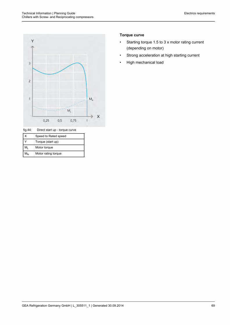
fig.44: Direct start up - torque curve
X Speed to Rated speed
Y Torque (start up)
ML Motor torque
MN Motor rating torque
Torque curve
• Starting torque 1.5 to 3 x motor rating current(depending on motor)
• Strong acceleration at high starting current
• High mechanical load
Technical Information | Planning GuideChillers with Screw- and Reciprocating compressors
Electrics requirements
GEA Refrigeration Germany GmbH | L_305511_1 | Generated 30.09.2014 69
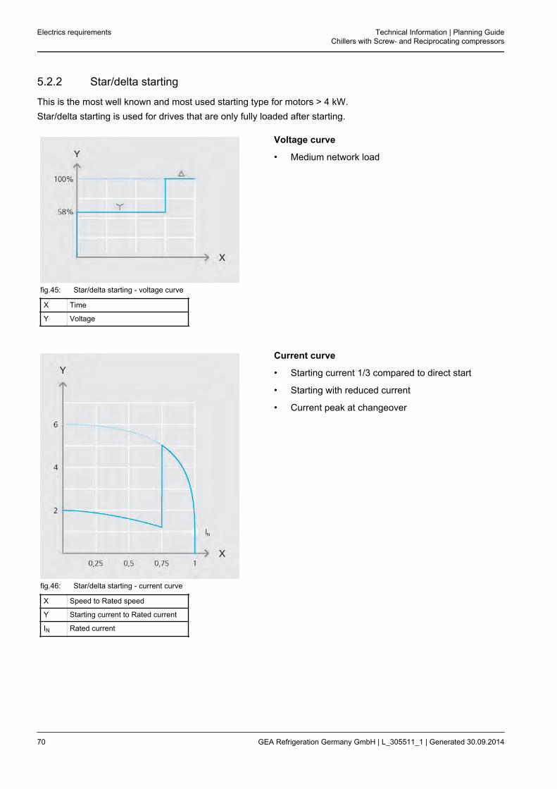
5.2.2 Star/delta starting
This is the most well known and most used starting type for motors > 4 kW.Star/delta starting is used for drives that are only fully loaded after starting.
fig.45: Star/delta starting - voltage curve
X Time
Y Voltage
Voltage curve
• Medium network load
fig.46: Star/delta starting - current curve
X Speed to Rated speed
Y Starting current to Rated current
IN Rated current
Current curve
• Starting current 1/3 compared to direct start
• Starting with reduced current
• Current peak at changeover
Electrics requirements Technical Information | Planning GuideChillers with Screw- and Reciprocating compressors
70 GEA Refrigeration Germany GmbH | L_305511_1 | Generated 30.09.2014
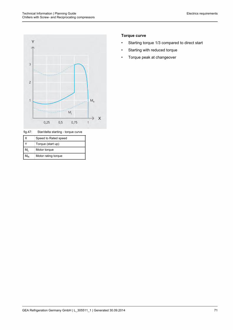
fig.47: Star/delta starting - torque curve
X Speed to Rated speed
Y Torque (start up)
ML Motor torque
MN Motor rating torque
Torque curve
• Starting torque 1/3 compared to direct start
• Starting with reduced torque
• Torque peak at changeover
Technical Information | Planning GuideChillers with Screw- and Reciprocating compressors
Electrics requirements
GEA Refrigeration Germany GmbH | L_305511_1 | Generated 30.09.2014 71

5.2.3 Soft starter
This type of starting allows a soft and low-noise motor start.The soft starter is used for drives where no impact load should occur.The starting current is not reduced like the star/delta starting.The disruptive current peaks at changeover are avoided. In the start phase of the motor the soft starter continu-ously controls the supply voltage through phase shift control up to the rated voltage.After the power-up a bypass contactor is switched on that then directly shifts the motor to the network voltage.Continuous speed control is not possible with a soft starter.
fig.48: Soft starter - voltage curve
X Time
Y Voltage
Voltage curve
• Medium network load
Electrics requirements Technical Information | Planning GuideChillers with Screw- and Reciprocating compressors
72 GEA Refrigeration Germany GmbH | L_305511_1 | Generated 30.09.2014
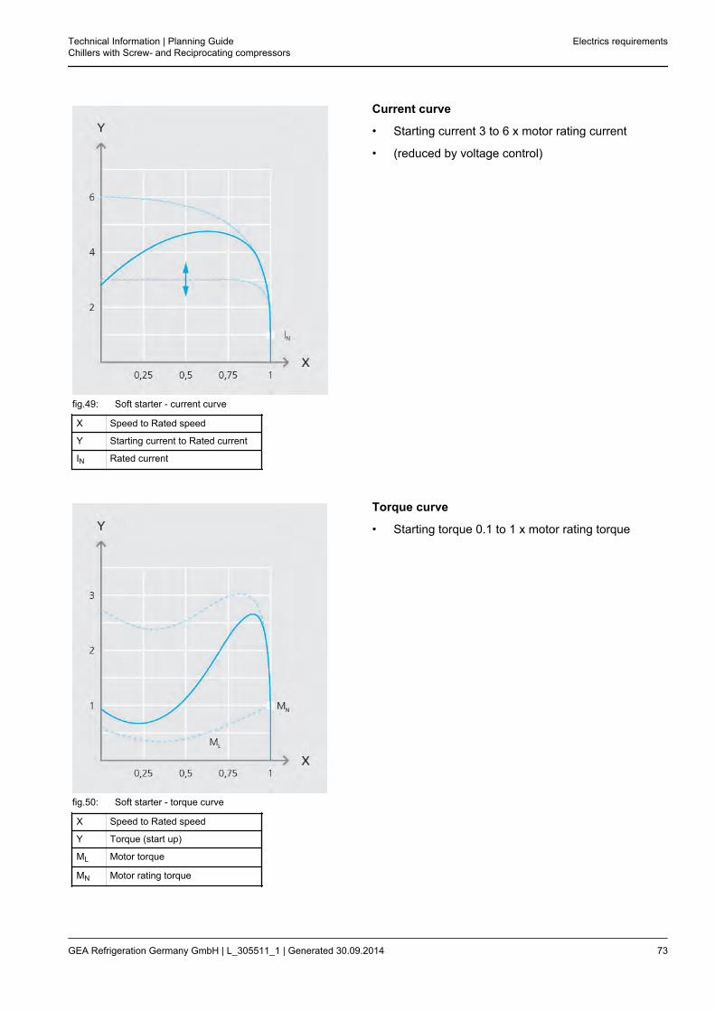
fig.49: Soft starter - current curve
X Speed to Rated speed
Y Starting current to Rated current
IN Rated current
Current curve
• Starting current 3 to 6 x motor rating current
• (reduced by voltage control)
fig.50: Soft starter - torque curve
X Speed to Rated speed
Y Torque (start up)
ML Motor torque
MN Motor rating torque
Torque curve
• Starting torque 0.1 to 1 x motor rating torque
Technical Information | Planning GuideChillers with Screw- and Reciprocating compressors
Electrics requirements
GEA Refrigeration Germany GmbH | L_305511_1 | Generated 30.09.2014 73

5.2.4 Frequency inverter
It allows a time-controlled motor start and operation with continuous motor speeds.The frequency inverter transforms the constant voltage and frequency of the supplying network into a direct volt-age.From this direct voltage (DC intermediate voltage) it creates a new three-phase network with variable voltageand variable frequency.In the process the frequency inverter takes almost only active power from the supplying network (cosPhi =1)The frequency inverter is used with controlled continuous speed regulation.
fig.51: Frequency inverter - voltage curve
X Time
Y Voltage
UBoost Starting Voltage
Voltage curve
• Low network load
Electrics requirements Technical Information | Planning GuideChillers with Screw- and Reciprocating compressors
74 GEA Refrigeration Germany GmbH | L_305511_1 | Generated 30.09.2014
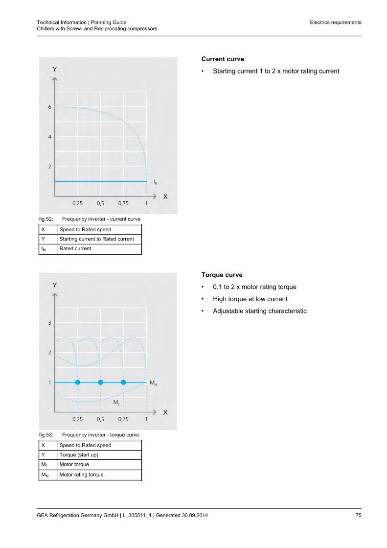
fig.52: Frequency inverter - current curve
X Speed to Rated speed
Y Starting current to Rated current
IN Rated current
Current curve
• Starting current 1 to 2 x motor rating current
fig.53: Frequency inverter - torque curve
X Speed to Rated speed
Y Torque (start up)
ML Motor torque
MN Motor rating torque
Torque curve
• 0.1 to 2 x motor rating torque
• High torque at low current
• Adjustable starting characteristic
Technical Information | Planning GuideChillers with Screw- and Reciprocating compressors
Electrics requirements
GEA Refrigeration Germany GmbH | L_305511_1 | Generated 30.09.2014 75

During operation with frequency inverters particular measures need to be taken to reduce or remove emittedinterference (emission) in the respective environment.First, the environmental category needs to be determined.For drive systems, one of four categories are used which are divided into 2 environmental areas.
1. Environment - residential areas:All areas of use that are residential or business and commercial areas and small businesses which aredirectly connected to the public power supply network. They do not have any high or medium voltage distri-bution transformers for separate supply.The environmental areas apply both inside and outside of buildings.
2. Environment - industrial areas:Industrial areas are areas of use that are not directly connected to the public power supply network but pos-sess their own high or medium voltage distribution transformers.In addition, they are defined as such in the land register and designated by particular electromagnetic condi-tions.
Category C1:Use in the residential area environmentRated voltage < 1000 V
Category C2:Use in residential area environment or industrial area environmentRated voltage < 1000 VNon-portableWarning required
Hint!
Connection and start-up may only take place by trained EMC competent personnel. 12
Category C3:Use in the industrial area environmentRated voltage < 1000 VWarning required
Category C4:Use in the industrial area environmentRated voltage > 1000 VNominal current > 400 AEMC planning required
Product standard EN 61800-3 (2005-07) for electrical drive systems
Arrangementaccording to cate-gory
C1 C2 C3 C4
Environment 1st environment1st or 2nd
environment2nd environment
12 EMC - electromagnetic compatibility
Electrics requirements Technical Information | Planning GuideChillers with Screw- and Reciprocating compressors
76 GEA Refrigeration Germany GmbH | L_305511_1 | Generated 30.09.2014
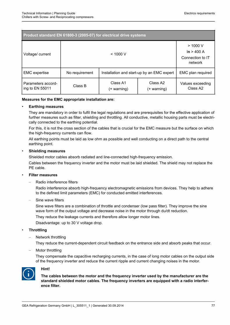
Product standard EN 61800-3 (2005-07) for electrical drive systems
Voltage/ current < 1000 V
> 1000 VIn > 400 A
Connection to ITnetwork
EMC expertise No requirement Installation and start-up by an EMC expert EMC plan required
Parameters accord-ing to EN 55011 Class B
Class A1(+ warning)
Class A2(+ warning)
Values exceedingClass A2
Measures for the EMC appropriate installation are:
• Earthing measuresThey are mandatory in order to fulfil the legal regulations and are prerequisites for the effective application offurther measures such as filter, shielding and throttling. All conductive, metallic housing parts must be electri-cally connected to the earthing potential.For this, it is not the cross section of the cables that is crucial for the EMC measure but the surface on whichthe high-frequency currents can flow.All earthing points must be laid as low ohm as possible and well conducting on a direct path to the centralearthing point.
• Shielding measuresShielded motor cables absorb radiated and line-connected high-frequency emission.Cables between the frequency inverter and the motor must be laid shielded. The shield may not replace thePE cable.
• Filter measures
– Radio interference filtersRadio interference absorb high-frequency electromagnetic emissions from devices. They help to adhereto the defined limit parameters (EMC) for conducted emitted interferences.
– Sine wave filtersSine wave filters are a combination of throttle and condenser (low pass filter). They improve the sinewave form of the output voltage and decrease noise in the motor through du/dt reduction.They reduce the leakage currents and therefore allow longer motor lines.Disadvantage: up to 30 V voltage drop.
• Throttling
– Network throttlingThey reduce the current-dependent circuit feedback on the entrance side and absorb peaks that occur.
– Motor throttlingThey compensate the capacitive recharging currents, in the case of long motor cables on the output sideof the frequency inverter and reduce the current ripple and current changing noises in the motor.
Hint!
The cables between the motor and the frequency inverter used by the manufacturer are thestandard shielded motor cables. The frequency inverters are equipped with a radio interfer-ence filter.
Technical Information | Planning GuideChillers with Screw- and Reciprocating compressors
Electrics requirements
GEA Refrigeration Germany GmbH | L_305511_1 | Generated 30.09.2014 77
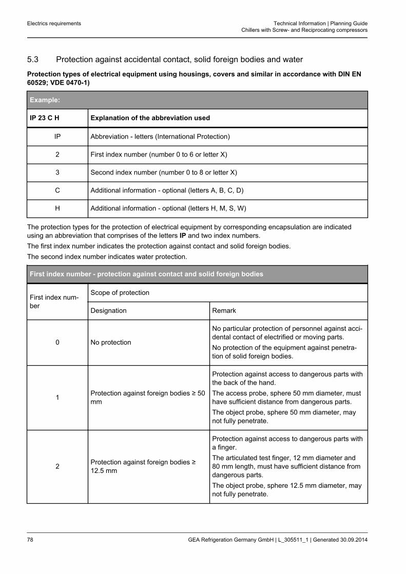
5.3 Protection against accidental contact, solid foreign bodies and water
Protection types of electrical equipment using housings, covers and similar in accordance with DIN EN60529; VDE 0470-1)
Example:
IP 23 C H Explanation of the abbreviation used
IP Abbreviation - letters (International Protection)
2 First index number (number 0 to 6 or letter X)
3 Second index number (number 0 to 8 or letter X)
C Additional information - optional (letters A, B, C, D)
H Additional information - optional (letters H, M, S, W)
The protection types for the protection of electrical equipment by corresponding encapsulation are indicatedusing an abbreviation that comprises of the letters IP and two index numbers.The first index number indicates the protection against contact and solid foreign bodies.The second index number indicates water protection.
First index number - protection against contact and solid foreign bodies
First index num-ber
Scope of protection
Designation Remark
0 No protection
No particular protection of personnel against acci-dental contact of electrified or moving parts.No protection of the equipment against penetra-tion of solid foreign bodies.
1 Protection against foreign bodies ≥ 50mm
Protection against access to dangerous parts withthe back of the hand.The access probe, sphere 50 mm diameter, musthave sufficient distance from dangerous parts.The object probe, sphere 50 mm diameter, maynot fully penetrate.
2 Protection against foreign bodies ≥12.5 mm
Protection against access to dangerous parts witha finger.The articulated test finger, 12 mm diameter and80 mm length, must have sufficient distance fromdangerous parts.The object probe, sphere 12.5 mm diameter, maynot fully penetrate.
Electrics requirements Technical Information | Planning GuideChillers with Screw- and Reciprocating compressors
78 GEA Refrigeration Germany GmbH | L_305511_1 | Generated 30.09.2014

First index number - protection against contact and solid foreign bodies
3 Protection against foreign bodies ≥2.5 mm
Protection against access to dangerous parts witha tool.The access probe, 2.5 mm diameter, may notpenetrate.The object probe, 2.5 mm diameter, may not pen-etrate at all.
4 Protection against foreign bodies ≥ 1mm
Protection against access to dangerous parts witha wire.The access probe, 1 mm diameter, may not pene-trate.The object probe, 1 mm diameter, may not pene-trate at all.
5 Protection against dust entry.
Protection against access to dangerous parts witha wire.The access probe, 1 mm diameter, may not pene-trate.Penetration of dust is not fully avoided but dustmust not enter in sufficient quantities to preventthe equipment from operating satisfactorily, or toimpair safety.
6 Dust density No entry of dust.
Second index number - water protection
Second indexnumber
Scope of protection
Designation Remark
0 No protection No particular protection.
1 Protection against dripping water fall-ing vertically
Water drops that fall vertically should not have anydamaging effect.
2 Protection against dripping water atup to 15° angle of the housing.
Water drops that fall vertically may not have anydamaging effect if the housing has an angle of 15°on both sides of the vertical.
3 Protection against sprayWater that is sprayed at any angle up to 60° onboth sides of the vertical must not have any dam-aging effect.
4 Protection against splashing water Water that sprays from all directions on the hous-ing must not have any damaging effect.
Technical Information | Planning GuideChillers with Screw- and Reciprocating compressors
Electrics requirements
GEA Refrigeration Germany GmbH | L_305511_1 | Generated 30.09.2014 79

Second index number - water protection
5 Protection against jets of waterA water jet from a nozzle which is directed from alldirections against the equipment, must not haveany damaging effect.
6 Protection against strong jets of waterWater that is directed at the housing from all direc-tions as a strong jet must not have any damagingeffect.
7 Protection against temporary immer-sion
Water must not penetrate in dangerous quantitiesif the equipment is immersed in water understandard pressure and time conditions.
8 Protection against lasting immersion
Water must penetrate in damaging quantities if theequipment is immersed in water for a long timeunder conditions that must be agreed between themanufacturer and user.The conditions must be more difficult than forindex number 7.
9K13 Protection at high pressure/steam jetcleaning
Water that is directed at the housing from all direc-tions under significantly increased pressure mustnot have any damaging effects.Water pressure 100 barWater temperature 80 °C
Additional information
Additional letter Additional information especially for
A Back of the hand
B Finger
C Tool
D Wire
H High voltage devices
M Movement during water test
S Stopped during water test
W Weather conditions
13 This index number comes from standard DIN 40050-9.
Electrics requirements Technical Information | Planning GuideChillers with Screw- and Reciprocating compressors
80 GEA Refrigeration Germany GmbH | L_305511_1 | Generated 30.09.2014
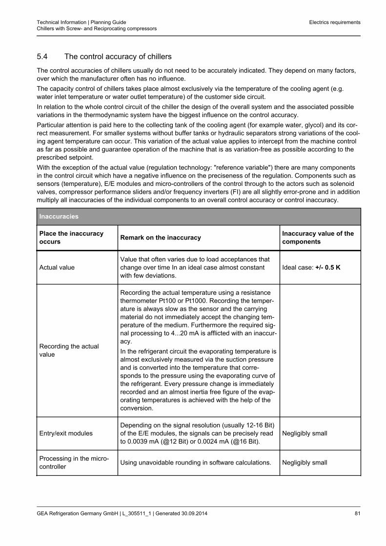
5.4 The control accuracy of chillers
The control accuracies of chillers usually do not need to be accurately indicated. They depend on many factors,over which the manufacturer often has no influence.The capacity control of chillers takes place almost exclusively via the temperature of the cooling agent (e.g.water inlet temperature or water outlet temperature) of the customer side circuit.In relation to the whole control circuit of the chiller the design of the overall system and the associated possiblevariations in the thermodynamic system have the biggest influence on the control accuracy.Particular attention is paid here to the collecting tank of the cooling agent (for example water, glycol) and its cor-rect measurement. For smaller systems without buffer tanks or hydraulic separators strong variations of the cool-ing agent temperature can occur. This variation of the actual value applies to intercept from the machine controlas far as possible and guarantee operation of the machine that is as variation-free as possible according to theprescribed setpoint.With the exception of the actual value (regulation technology: "reference variable") there are many componentsin the control circuit which have a negative influence on the preciseness of the regulation. Components such assensors (temperature), E/E modules and micro-controllers of the control through to the actors such as solenoidvalves, compressor performance sliders and/or frequency inverters (FI) are all slightly error-prone and in additionmultiply all inaccuracies of the individual components to an overall control accuracy or control inaccuracy.
Inaccuracies
Place the inaccuracyoccurs Remark on the inaccuracy Inaccuracy value of the
components
Actual valueValue that often varies due to load acceptances thatchange over time In an ideal case almost constantwith few deviations.
Ideal case: +/- 0.5 K
Recording the actualvalue
Recording the actual temperature using a resistancethermometer Pt100 or Pt1000. Recording the temper-ature is always slow as the sensor and the carryingmaterial do not immediately accept the changing tem-perature of the medium. Furthermore the required sig-nal processing to 4...20 mA is afflicted with an inaccur-acy.In the refrigerant circuit the evaporating temperature isalmost exclusively measured via the suction pressureand is converted into the temperature that corre-sponds to the pressure using the evaporating curve ofthe refrigerant. Every pressure change is immediatelyrecorded and an almost inertia free figure of the evap-orating temperatures is achieved with the help of theconversion.
Entry/exit modulesDepending on the signal resolution (usually 12-16 Bit)of the E/E modules, the signals can be precisely readto 0.0039 mA (@12 Bit) or 0.0024 mA (@16 Bit).
Negligibly small
Processing in the micro-controller Using unavoidable rounding in software calculations. Negligibly small
Technical Information | Planning GuideChillers with Screw- and Reciprocating compressors
Electrics requirements
GEA Refrigeration Germany GmbH | L_305511_1 | Generated 30.09.2014 81
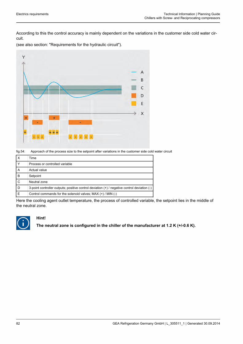
According to this the control accuracy is mainly dependent on the variations in the customer side cold water cir-cuit.(see also section: "Requirements for the hydraulic circuit").
fig.54: Approach of the process size to the setpoint after variations in the customer side cold water circuit
X Time
Y Process or controlled variable
A Actual value
B Setpoint
C Neutral zone
D 3-point controller outputs; positive control deviation (+) / negative control deviation (-)
E Control commands for the solenoid valves; MAX (+) / MIN (-)
Here the cooling agent outlet temperature, the process of controlled variable, the setpoint lies in the middle ofthe neutral zone.
Hint!
The neutral zone is configured in the chiller of the manufacturer at 1.2 K (+/-0.6 K).
Electrics requirements Technical Information | Planning GuideChillers with Screw- and Reciprocating compressors
82 GEA Refrigeration Germany GmbH | L_305511_1 | Generated 30.09.2014
5.5 Communication
When arranging many packages or chillers in a system structure it is possible to operate the individual productsin sequence with a higher-level master control. The central commands can be sent by the master control to thelocal package control devices using potential-free contacts or network signals!The following status couplings are possible:
• MPI
• Profibus DP
• Modbus TCP
• Modbus RTU
• Ethernet/IP coupling IPTherefore it is possible to monitor and if necessary change the operation modes, actual values, setpoints, warn-ings and failures of the individual machines via the master control.
Hint!
See the communication guideline for more information.
Technical Information | Planning GuideChillers with Screw- and Reciprocating compressors
Electrics requirements
GEA Refrigeration Germany GmbH | L_305511_1 | Generated 30.09.2014 83
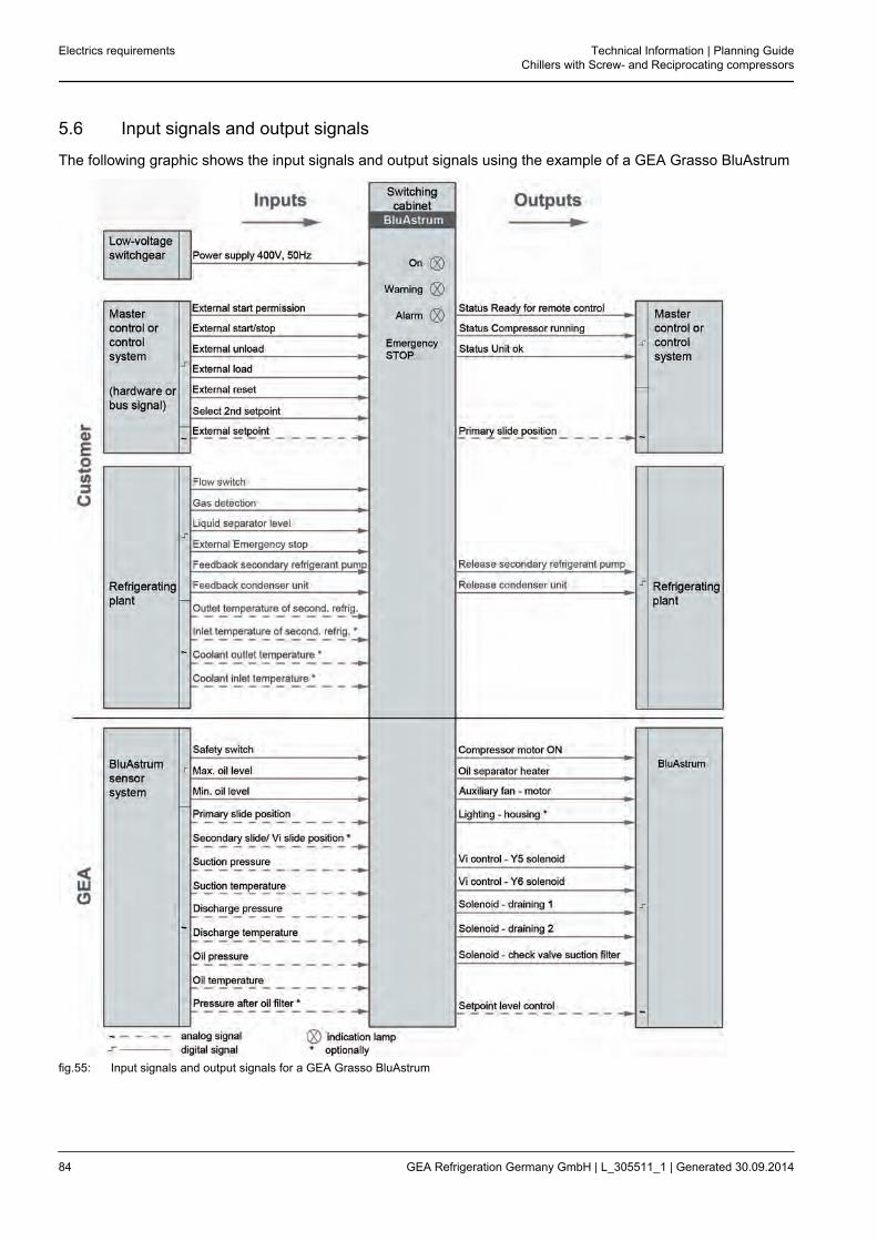
5.6 Input signals and output signals
The following graphic shows the input signals and output signals using the example of a GEA Grasso BluAstrum
fig.55: Input signals and output signals for a GEA Grasso BluAstrum
Electrics requirements Technical Information | Planning GuideChillers with Screw- and Reciprocating compressors
84 GEA Refrigeration Germany GmbH | L_305511_1 | Generated 30.09.2014
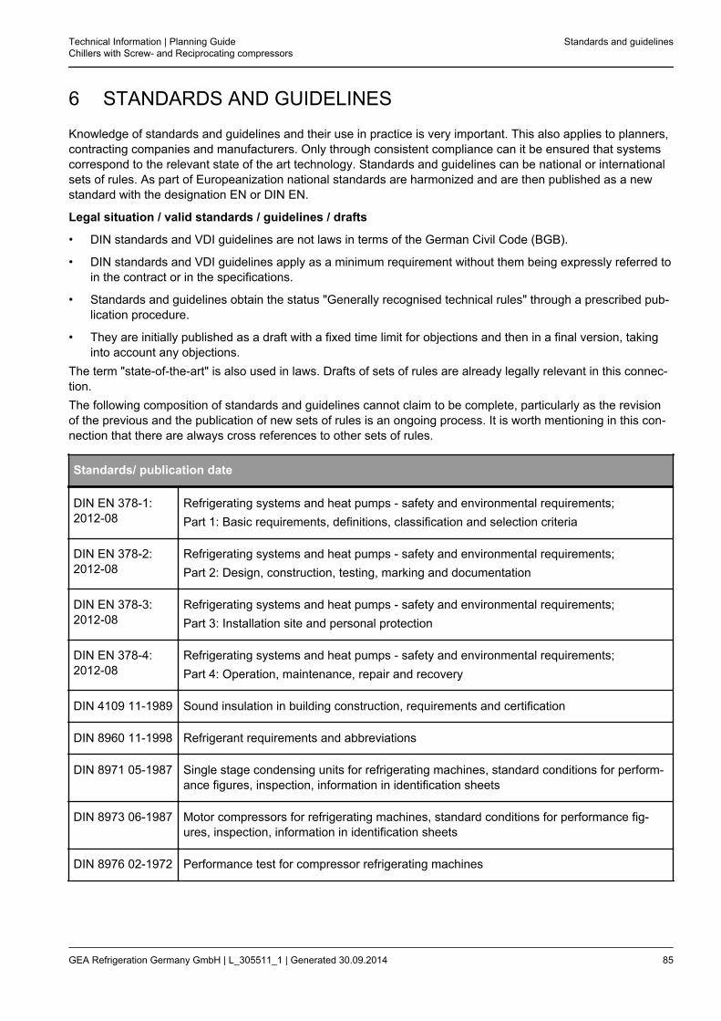
6 STANDARDS AND GUIDELINES
Knowledge of standards and guidelines and their use in practice is very important. This also applies to planners,contracting companies and manufacturers. Only through consistent compliance can it be ensured that systemscorrespond to the relevant state of the art technology. Standards and guidelines can be national or internationalsets of rules. As part of Europeanization national standards are harmonized and are then published as a newstandard with the designation EN or DIN EN.
Legal situation / valid standards / guidelines / drafts
• DIN standards and VDI guidelines are not laws in terms of the German Civil Code (BGB).
• DIN standards and VDI guidelines apply as a minimum requirement without them being expressly referred toin the contract or in the specifications.
• Standards and guidelines obtain the status "Generally recognised technical rules" through a prescribed pub-lication procedure.
• They are initially published as a draft with a fixed time limit for objections and then in a final version, takinginto account any objections.
The term "state-of-the-art" is also used in laws. Drafts of sets of rules are already legally relevant in this connec-tion.The following composition of standards and guidelines cannot claim to be complete, particularly as the revisionof the previous and the publication of new sets of rules is an ongoing process. It is worth mentioning in this con-nection that there are always cross references to other sets of rules.
Standards/ publication date
DIN EN 378-1:2012-08
Refrigerating systems and heat pumps - safety and environmental requirements;Part 1: Basic requirements, definitions, classification and selection criteria
DIN EN 378-2:2012-08
Refrigerating systems and heat pumps - safety and environmental requirements;Part 2: Design, construction, testing, marking and documentation
DIN EN 378-3:2012-08
Refrigerating systems and heat pumps - safety and environmental requirements;Part 3: Installation site and personal protection
DIN EN 378-4:2012-08
Refrigerating systems and heat pumps - safety and environmental requirements;Part 4: Operation, maintenance, repair and recovery
DIN 4109 11-1989 Sound insulation in building construction, requirements and certification
DIN 8960 11-1998 Refrigerant requirements and abbreviations
DIN 8971 05-1987 Single stage condensing units for refrigerating machines, standard conditions for perform-ance figures, inspection, information in identification sheets
DIN 8973 06-1987 Motor compressors for refrigerating machines, standard conditions for performance fig-ures, inspection, information in identification sheets
DIN 8976 02-1972 Performance test for compressor refrigerating machines
Technical Information | Planning GuideChillers with Screw- and Reciprocating compressors
Standards and guidelines
GEA Refrigeration Germany GmbH | L_305511_1 | Generated 30.09.2014 85
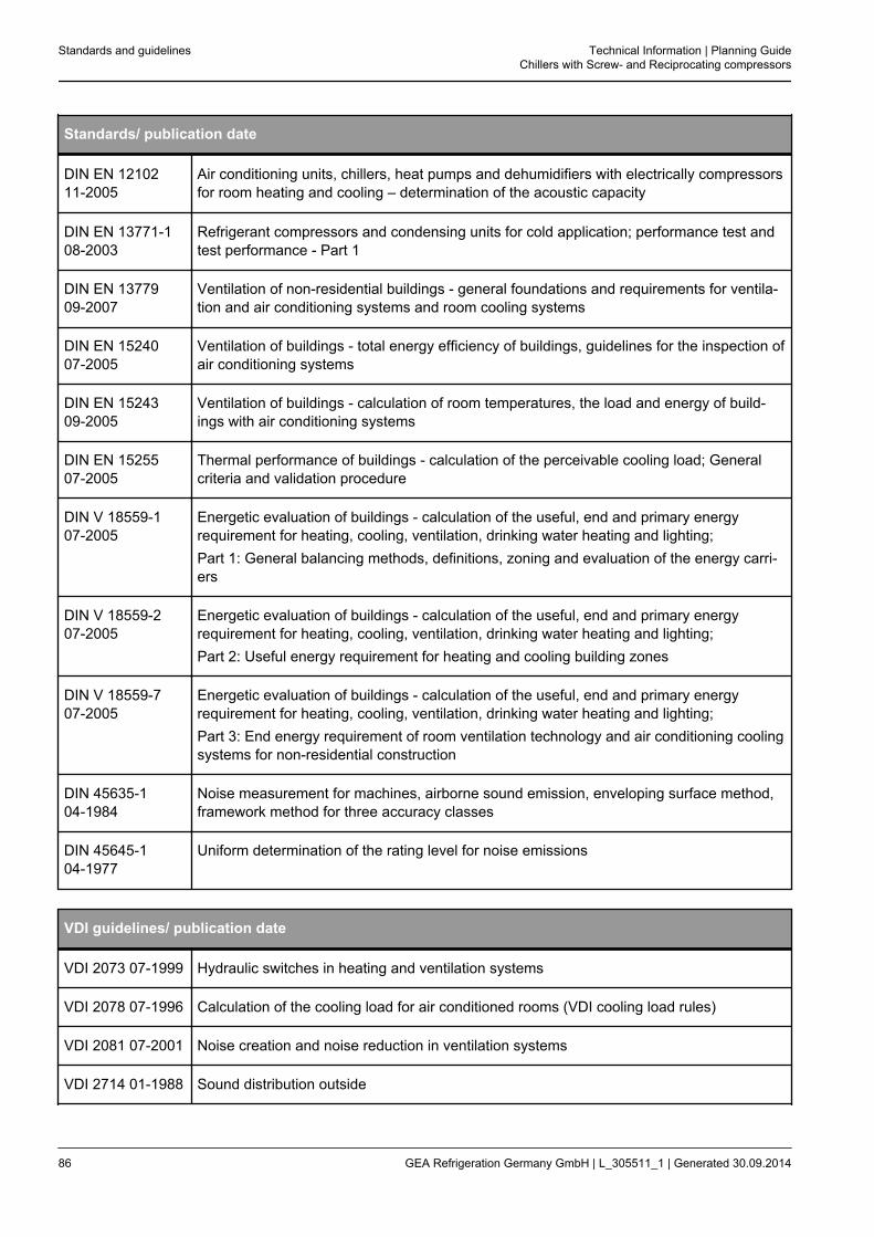
Standards/ publication date
DIN EN 1210211-2005
Air conditioning units, chillers, heat pumps and dehumidifiers with electrically compressorsfor room heating and cooling – determination of the acoustic capacity
DIN EN 13771-108-2003
Refrigerant compressors and condensing units for cold application; performance test andtest performance - Part 1
DIN EN 1377909-2007
Ventilation of non-residential buildings - general foundations and requirements for ventila-tion and air conditioning systems and room cooling systems
DIN EN 1524007-2005
Ventilation of buildings - total energy efficiency of buildings, guidelines for the inspection ofair conditioning systems
DIN EN 1524309-2005
Ventilation of buildings - calculation of room temperatures, the load and energy of build-ings with air conditioning systems
DIN EN 1525507-2005
Thermal performance of buildings - calculation of the perceivable cooling load; Generalcriteria and validation procedure
DIN V 18559-107-2005
Energetic evaluation of buildings - calculation of the useful, end and primary energyrequirement for heating, cooling, ventilation, drinking water heating and lighting;Part 1: General balancing methods, definitions, zoning and evaluation of the energy carri-ers
DIN V 18559-207-2005
Energetic evaluation of buildings - calculation of the useful, end and primary energyrequirement for heating, cooling, ventilation, drinking water heating and lighting;Part 2: Useful energy requirement for heating and cooling building zones
DIN V 18559-707-2005
Energetic evaluation of buildings - calculation of the useful, end and primary energyrequirement for heating, cooling, ventilation, drinking water heating and lighting;Part 3: End energy requirement of room ventilation technology and air conditioning coolingsystems for non-residential construction
DIN 45635-104-1984
Noise measurement for machines, airborne sound emission, enveloping surface method,framework method for three accuracy classes
DIN 45645-104-1977
Uniform determination of the rating level for noise emissions
VDI guidelines/ publication date
VDI 2073 07-1999 Hydraulic switches in heating and ventilation systems
VDI 2078 07-1996 Calculation of the cooling load for air conditioned rooms (VDI cooling load rules)
VDI 2081 07-2001 Noise creation and noise reduction in ventilation systems
VDI 2714 01-1988 Sound distribution outside
Standards and guidelines Technical Information | Planning GuideChillers with Screw- and Reciprocating compressors
86 GEA Refrigeration Germany GmbH | L_305511_1 | Generated 30.09.2014
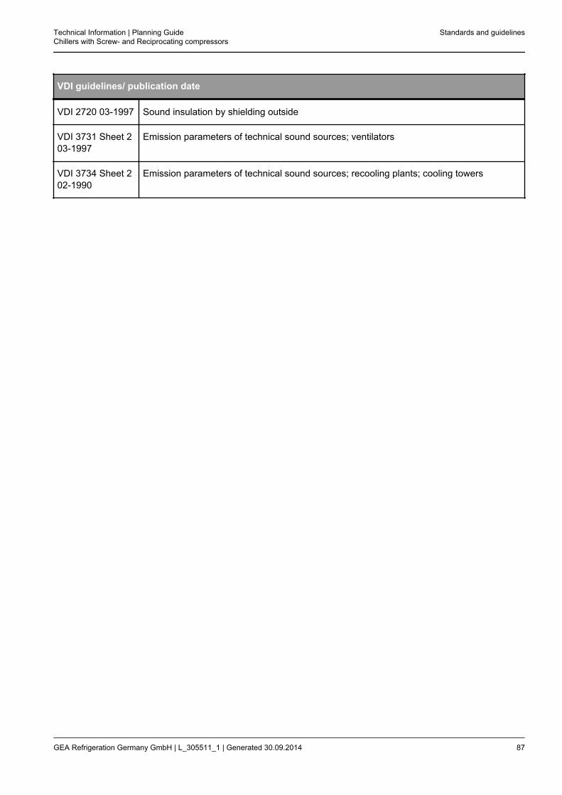
VDI guidelines/ publication date
VDI 2720 03-1997 Sound insulation by shielding outside
VDI 3731 Sheet 203-1997
Emission parameters of technical sound sources; ventilators
VDI 3734 Sheet 202-1990
Emission parameters of technical sound sources; recooling plants; cooling towers
Technical Information | Planning GuideChillers with Screw- and Reciprocating compressors
Standards and guidelines
GEA Refrigeration Germany GmbH | L_305511_1 | Generated 30.09.2014 87

© G
EA. A
ll rig
hts
rese
rved
. Sub
ject
to m
odifi
catio
n
We live our values.Excellence • Passion • Integrity • Responsibility • GEA-versity
GEA Group is a global engineering company with multi-billion euro sales and operations in more than
50 countries. Founded in 1881, the company is one of the largest providers of innovative equipment and
process technology. GEA Group is listed in the STOXX® Europe 600 Index.
GEA Refrigeration Technologies
GEA Refrigeration Germany GmbH
Holzhauser Str. 165, 13509 Berlin, GermanyPhone: +49 30 435 92 600, Fax: +49 30 435 92 [email protected], www.gea.com