GEA Grasso 5HP refrigeration Reciprocating Compressors for ... Documents/Grasso Piston Co… ·...
52
Reciprocating Compressors for industrial refrigeration GEA Grasso 5HP Installation and Maintenance Manual 0089205gbr_8
Transcript of GEA Grasso 5HP refrigeration Reciprocating Compressors for ... Documents/Grasso Piston Co… ·...
Reciprocating Compressors for industrialrefrigerationGEA Grasso 5HP
Installation and Maintenance Manual0089205gbr_8

COPYRIGHT
All Rights reserved. No part of this publication may be copied or published bymeans of printing, photocopying, microfilm or otherwise without prior writtenconsent of Grasso.This restriction also applies to the corresponding drawings and diagrams.
LEGAL NOTICE
This publication has been written in good faith. However, Grasso cannot be heldresponsible, neither for any errors occurring in this publication nor for theirconsequences.
0089205gbr_82 22.03.2017
SYMBOLS USED
Danger
Stands for an immediate danger which leads to heavy physical injuriesor to the death.
Warning
Stands for a possibly dangerous situation which leads to heavyphysical injuries or to the death.
Caution!
Stands for a possibly dangerous situation which could lead to lightphysical injuries or to damages to property.
Hint!
Stands for an important tip whose attention is important for thedesignated use and function of the device.
SAFETY INSTRUCTIONS
Hint!
This manual must be carefull read and understood prior to installingand servicing the compressor (package)
Safety
This manual is written with great care, but the contractor/installer is heldresponsible to examine this information and to take care of possible additionaland/ or deviated safety measures.
Safety instructions
It is the task of the contractor/installer to inform and explain to his client theoperation of the compressor (Package).Do respect all federal, state or local safety regulations/legislations duringinstalling, connecting and operating this compressor (package).
Construction changes
Warning
In compliance with the regulations of the Pressure EquipmentDirective it is mandatory that no changes be made to the constructionof pressurised parts such as the crankcase housing, suction filterhousing etc.
Installer oriented information
The compressor (package) is filled with nitrogen to prevent penetration ofmoisture. Therefore, keep the compressor closed until the compressor (package)is being installed.
0089205gbr_8 22.03.2017 3
Warning The compressor is not filled with oil.
Hint!
After the successful initial run of the compressor (package) thewarranty chart must be filled in and returned to Grasso. A warrantychart is attached to each compressor.
0089205gbr_84 22.03.2017
PREFACE
General
1. All documentation can be downloaded via our web site.
2. Grasso’s technical manuals includes “generic paragraphs”; this means that itcan occur that not all data as described is relevant for the currentcompressor series as mentioned in this manual. (For instance, not allcompressor series are suitable for all mentioned refrigerants or not allcompressor series includes two-stage compressors)
Directives
Equipment is based on Pressure Equipment Directive (PED 97/23/EG)regulations and according to Machine Directive (MD 2006/42/EG) regulations.
The applied standards are:NEN-EN-IEC 60204, NEN-EN-ISO 12100, NEN-EN-ISO 13857, NEN-EN 378
0089205gbr_8 22.03.2017 5

0089205gbr_86 22.03.2017

GENERAL INFO 5HP
Main setup data Grasso 5HP
Description Value Remark
General limits of operation
Caution!
Refer to Product InformationSection 4.1, Page 46
Refer to Product InformationSection 4.1, Page 46
Start frequency max. 6 starts per hour
Time interval between stoppingand re-starting min. 2 minutes
Time interval between startingand re-starting min. 10 minutes
Time interval between capacitysteps min. 3 minutes
For continuous minimum part-load (i.e. more than 30 minutes)
consult GrassoAdjust the steps between up anddown loading, in such a way that
the system is running stable
Oil level 25-75% crankcase sight glass
Lubricating oil pressuredifference
between 1.3 and 3.0 bar Settingapprox. 2.0 bar
After a mimimum of 15 minutesrunning time at an oil
temperature of approx. 35 oC (95oF)
Oil discharge - running in - filter Red coloured filter element
Factory mounted; to bereplaced after max. 100
running hours by permanent oildischarge filter element
Oil discharge - permanent - filter Grey filter element Supplied loose; replacement forfactory mounted running in filter
Standard direction of rotation ofcompressor drive shaft
Counterclockwise when facing shaftend
Cylinder numbering
1
S S
2
3
3
44
56
2 1
Fig.1: Top view compressor (S=shaft end)
0089205gbr_8 22.03.2017 7

0089205gbr_88 22.03.2017
TABLE OF CONTENTS1 INSTALLATION AND PREPARATION FOR USE 111.1 Running-in oil filter has to be installed after an overhaul or big repair 111.2 INSTALLATION 111.2.1 Moving instructions and storage 121.2.2 Storage 121.2.3 Hoisting and moving instructions 121.2.4 Required free space 131.2.5 Foundation requirements 14
Concrete structure 14Anchoring 15Mounting the base frame on a concrete block 16Mounting bare compressor on a concrete block 17
1.2.6 Connecting to refrigerating system pipework 181.2.7 Connecting the power supply 191.2.8 Earthing connections 191.2.9 Separately delivered components 191.3 PREPARATIONS FOR USE 201.3.1 Measures for NH3 heat pumps 201.3.2 Leak test of compressor and system 241.3.3 EVACUATION/DRYING THE REFRIGERATING SYSTEM 241.3.4 Initial oil charge 241.3.5 Initial refrigerant charge 251.3.6 Adjustment of instruments and safety devices 25
CONTROL DEVICES 25Grasso 5HP 25Re-adjustment of oil pressure regulator 25
1.3.7 Checking direction of rotation of motor shaft 261.3.8 Installing the drive guards (if present) 261.3.9 Initial oil warm up 271.3.10 Initial start-up 27
Limitations of part load operation and start-up 27Frequency controlled compressor 27Pre-start check list 27
1.3.11 Starting and stopping procedures 28First start 28Restart 29Restart after a short standstill period of time (less than 1 month) 29Restart after a long standstill period of time 29Stopping the compressor 29
2 INSPECTION AND TROUBLE SHOOTING 302.1 Periodical inspection 302.2 Survey of periodical inspections 302.2.1 Check list periodical inspection 312.3 STEPS FOR LONGER SHUT-DOWN PERIODS (> 6 months) 312.4 LUBRICATION DATA 322.4.1 Topping up oil with compressor operating 322.5 EVACUATION, LEAK TESTING AND START-UP OF THE COMPRESSOR/PACKAGE 322.5.1 EVACUATION OF REFRIGERANT BEFORE SERVICING 332.5.2 LEAK-TIGHTNESS AFTER SERVICING 332.5.3 EVACUATION AFTER SERVICING 332.5.4 START-UP AFTER SERVICING 332.6 DRAINING AND CHANGE OF OIL 342.7 Oil discharge filter 342.8 OIL SUCTION AND DISCHARGE FILTERS 342.9 REPLACEMENT OF SUCTION GAS FILTER(S) 342.10 DISMANTLING, INSPECTION AND RE-ASSEMBLY OF SUCTION AND DISCHARGE VALVES 352.11 COMPRESSOR PURGING 352.12 TROUBLESHOOTING TABLE GRASSO RECIPROCATING COMPRESSORS 363 MAINTENANCE 393.1 Spare parts manual 39
0089205gbr_8 22.03.2017 9
3.2 Post start-up maintenance 393.3 First maintenance 393.4 Legend 403.4.1 SMS Grasso 5HP 403.4.2 Checklist 403.5 Grasso 5HP R744 & R717 434 APPENDIX; Product Information (PI) 464.1 GENERAL LIMITS AND FIELDS OF OPERATION GRASSO 5HP 464.2 PART-LOAD POWER CONSUMPTION AND ALLOWED PART LOAD STEPS 474.3 CAPACITY CONTROL 474.4 LUBRICATING OILS (choice and recommendations Grasso HP) 494.5 Pre-lubrication oil system 49
0089205gbr_810 22.03.2017

1 INSTALLATION AND PREPARATION FOR USE
1.1 Running-in oil filter has to be installed after an overhaul or big repair
Hint!
This is why and when the running in oil filters are required:
Warning
A running in oil filter has always to be installed after an overhaul orbig repair for the 1st 100 hours of operation!The oil and oil oil filters have to be replaced by new oil and filters.Due to running-in wear of liners and piston rings, it's normal that theoil becomes grey during the 1st 100 operating hours.After 100 operating hours, the oil could slightly become clear again.
1.2 INSTALLATION
Warning
The compressor is not charged with oil, therefore, DO NOT start thecompressor before it has been installed and prepared according toGrasso’s instructions.
This section contains instructions for the proper installation of a Grassocompressor (package). Before the compressor (package) is ready for the initialstart up, the installation instructions in the following paragraphs must be followed:
1. The Compressor (Package) should be levelled and securely anchored to thefoundation.
2. All piping should be completed.
3. The system and the compressor are to be pressure tested for leaks (see.Section 1.3.2, Page 24)
4. The system should be evacuated to remove air and moisture.
5. The electric wiring should be completed as per wiring diagrams. Do notenergise the main power control cabinet until oil is added and the direction ofrotation has been checked.
6. The compressor is to be filled with the correct type and amount of lubricatingoil and has to be pre-lubricated (Refer Section 4.5, Page 49) before the firststart.
7. ‘Open compressors’ only;
7.1 Open compressors;The drive system should be installed.
7.2 (Semi) hermitic compressors;Mark R-S-T-N power supply in the terminal box of the motor.
INSTALLATION AND PREPARATION FOR USERunning-in oil filter has to be installed after an overhaul or big repair
0089205gbr_8 22.03.2017 11
8. The system should be charged with the correct amount of refrigerant.
9. The oil should be warmed up above minimum start up oil temperature (see"Product Information").
10. The control cabinet should be energised to check the package controls.
Hint!
Do not forget to charge the oil separator (if present) initially with oil, tothe level of the float assembly
1.2.1 Moving instructions and storage
For loose component or compressor package weights, refer either to the relevantcomponent type plate or package lay-out or to the suppliers document. For barecompressor weights, see "Product Information".
Caution!
Every precaution must be taken while moving the package to its finallocation. Pushing, pulling or climbing on any package component orpiping, can easily create damage.
1.2.2 Storage
The compressor (package) is filled with dry nitrogen. Keep the system closeduntil the package is installed. If the compressor (package) is stored, it should bekept at all times in a dry location to prevent corrosion damage. If the compressor(package) is to be stored for a prolonged period of time, it should be checkedweekly to ensure that the holding charge of dry nitrogen remains aboveatmospheric pressure.
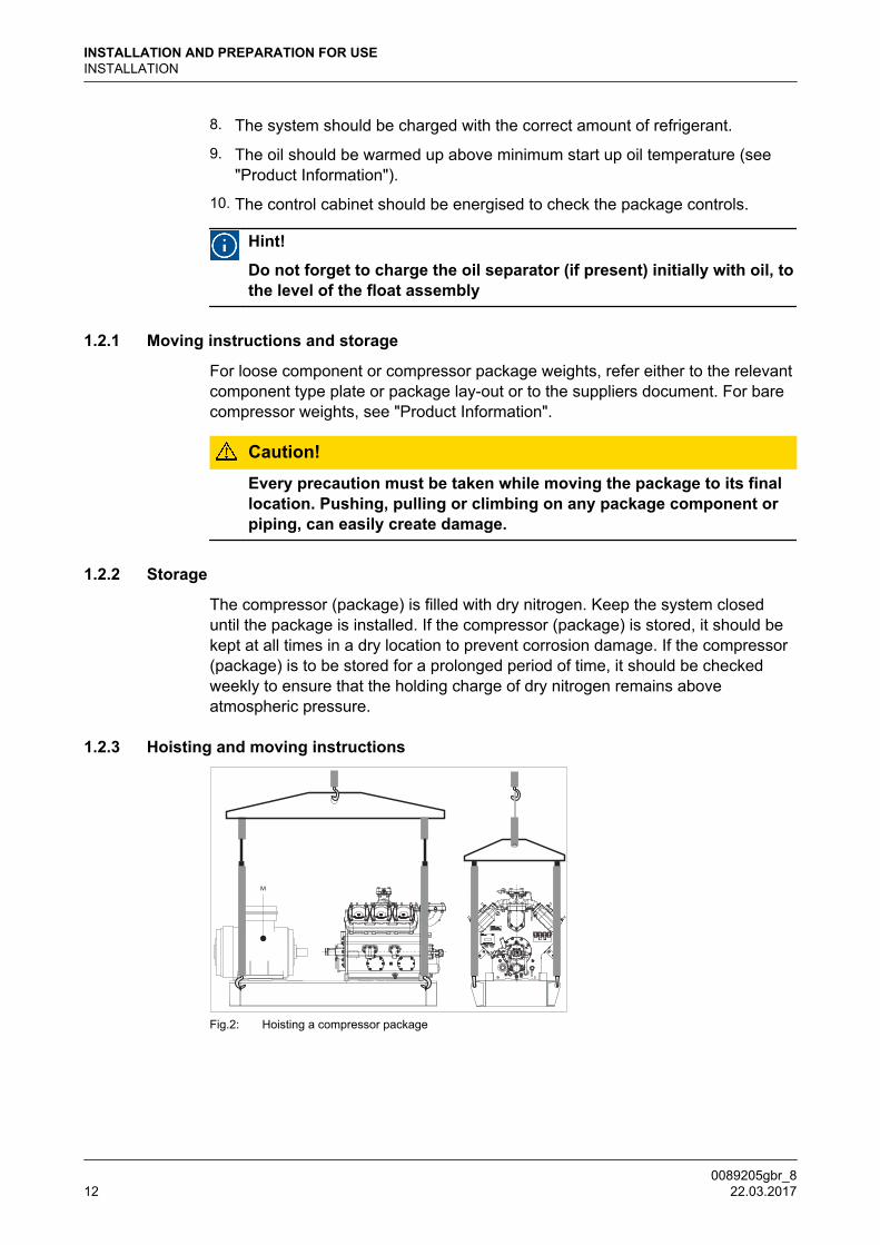
1.2.3 Hoisting and moving instructions
Fig.2: Hoisting a compressor package
INSTALLATION AND PREPARATION FOR USEINSTALLATION
0089205gbr_812 22.03.2017
Packaged base frame:
The only places that can be used for safe hoisting of the package are the fourhoisting eyes on the steel base frame as shown in the above figure. Prior tohoisting a compressor package with a V-belt drive arrangement, the factorymounted drive guard has to be removed. Attach spreader bars to the slings so asto prevent damage to piping and components.
Warning
DO NOT use the compressor or motor or oil separator hoisting eyes tomove the package! These hoisting eyes are intended for lifting loosecomponents only and not for the entire package!
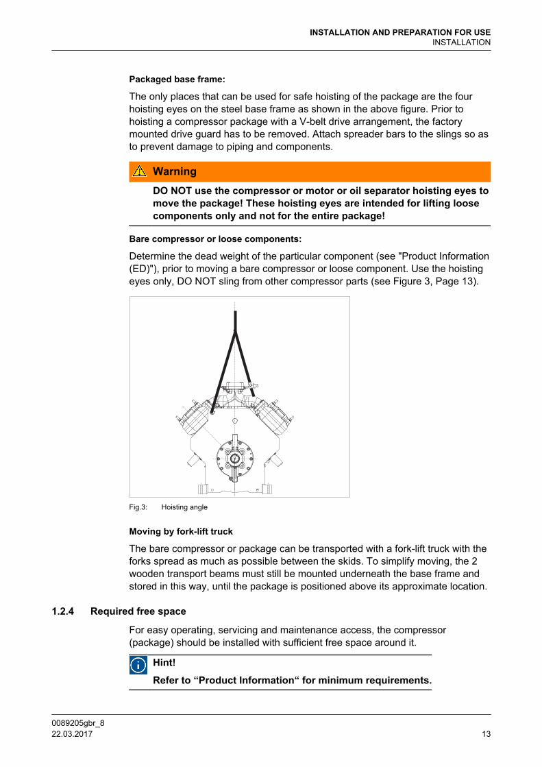
Bare compressor or loose components:
Determine the dead weight of the particular component (see "Product Information(ED)"), prior to moving a bare compressor or loose component. Use the hoistingeyes only, DO NOT sling from other compressor parts (see Figure 3, Page 13).
Fig.3: Hoisting angle
Moving by fork-lift truck
The bare compressor or package can be transported with a fork-lift truck with theforks spread as much as possible between the skids. To simplify moving, the 2wooden transport beams must still be mounted underneath the base frame andstored in this way, until the package is positioned above its approximate location.
1.2.4 Required free space
For easy operating, servicing and maintenance access, the compressor(package) should be installed with sufficient free space around it.
Hint!
Refer to “Product Information“ for minimum requirements.
INSTALLATION AND PREPARATION FOR USEINSTALLATION
0089205gbr_8 22.03.2017 13
1.2.5 Foundation requirements
Hint!
Compressor (package) has to be mounted on a concreted block. Onrequest, Grasso can calculate the exact dimensions of the concreteblock, based on the compressor size and operating conditions.
This paragraph covers measures to be taken for a compressor (package)mounting on a concrete block.Two foundation arrangements are described:
1. Compressor package with steel base frame mounted on a concrete block.Following base frames are possible;
1.a Frame designed for mounting on concrete block.For more instalation details refer to; Section 1.2.5.1, Page 14,Section 1.2.5.2, Page 15, Section 1.2.5.3, Page 16, Section ,Page 17, Section , Page 17.
1.b Frame designed for mounting on vibration dampers.For more details in case mounting base frames on vibration dampers isapplied, refer to separate instruction sheet and other orderdocumentation like package drawing, supplied with the compressorpackage and consult Grasso if required.
2. Bare compressor direct mounted on a concrete block via grouted anchors.For more installation details refer to; Section 1.2.5.1, Page 14,Section 1.2.5.2, Page 15, Section 1.2.5.4, Page 17.
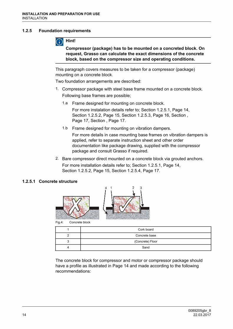
1.2.5.1 Concrete structure
Fig.4: Concrete block
1 Cork board
2 Concrete base
3 (Concrete) Floor
4 Sand
The concrete block for compressor and motor or compressor package shouldhave a profile as illustrated in Page 14 and made according to the followingrecommendations:
INSTALLATION AND PREPARATION FOR USEINSTALLATION
0089205gbr_814 22.03.2017
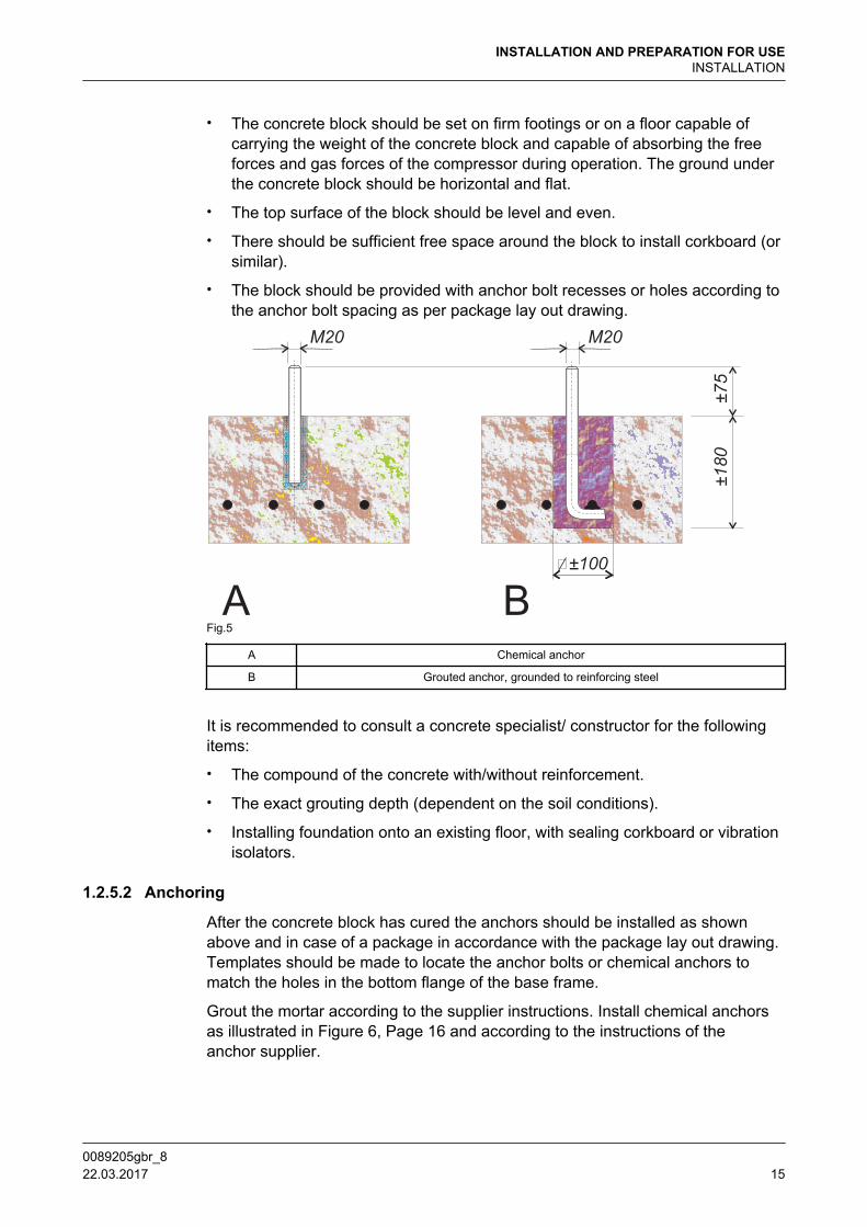
• The concrete block should be set on firm footings or on a floor capable ofcarrying the weight of the concrete block and capable of absorbing the freeforces and gas forces of the compressor during operation. The ground underthe concrete block should be horizontal and flat.
• The top surface of the block should be level and even.
• There should be sufficient free space around the block to install corkboard (orsimilar).
• The block should be provided with anchor bolt recesses or holes according tothe anchor bolt spacing as per package lay out drawing.
Fig.5
A Chemical anchor
B Grouted anchor, grounded to reinforcing steel
It is recommended to consult a concrete specialist/ constructor for the followingitems:
• The compound of the concrete with/without reinforcement.
• The exact grouting depth (dependent on the soil conditions).
• Installing foundation onto an existing floor, with sealing corkboard or vibrationisolators.
1.2.5.2 Anchoring
After the concrete block has cured the anchors should be installed as shownabove and in case of a package in accordance with the package lay out drawing.Templates should be made to locate the anchor bolts or chemical anchors tomatch the holes in the bottom flange of the base frame.
Grout the mortar according to the supplier instructions. Install chemical anchorsas illustrated in Figure 6, Page 16 and according to the instructions of theanchor supplier.
INSTALLATION AND PREPARATION FOR USEINSTALLATION
0089205gbr_8 22.03.2017 15
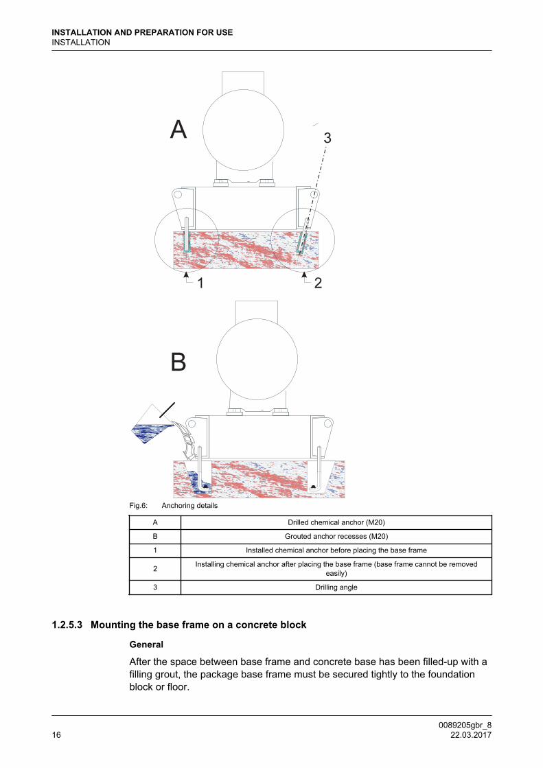
Fig.6: Anchoring details
A Drilled chemical anchor (M20)
B Grouted anchor recesses (M20)
1 Installed chemical anchor before placing the base frame
2 Installing chemical anchor after placing the base frame (base frame cannot be removedeasily)
3 Drilling angle
1.2.5.3 Mounting the base frame on a concrete block
General
After the space between base frame and concrete base has been filled-up with afilling grout, the package base frame must be secured tightly to the foundationblock or floor.
INSTALLATION AND PREPARATION FOR USEINSTALLATION
0089205gbr_816 22.03.2017
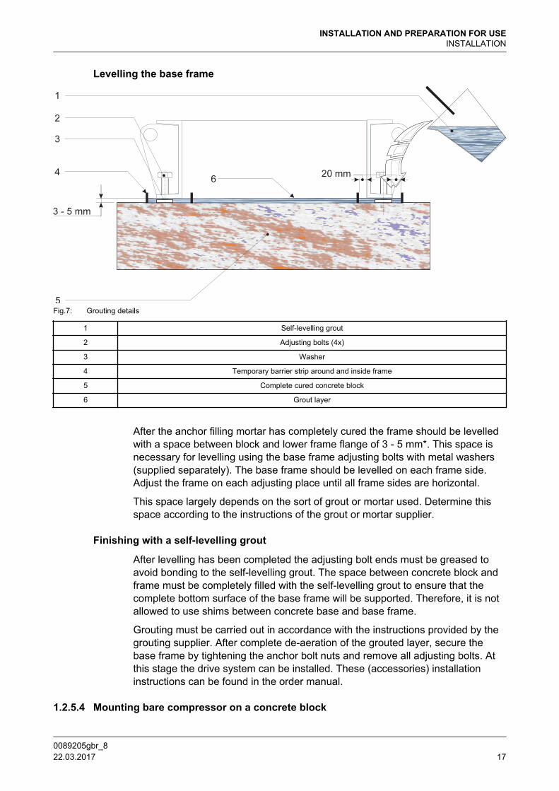
Levelling the base frame
Fig.7: Grouting details
1 Self-levelling grout
2 Adjusting bolts (4x)
3 Washer
4 Temporary barrier strip around and inside frame
5 Complete cured concrete block
6 Grout layer
After the anchor filling mortar has completely cured the frame should be levelledwith a space between block and lower frame flange of 3 - 5 mm*. This space isnecessary for levelling using the base frame adjusting bolts with metal washers(supplied separately). The base frame should be levelled on each frame side.Adjust the frame on each adjusting place until all frame sides are horizontal.
This space largely depends on the sort of grout or mortar used. Determine thisspace according to the instructions of the grout or mortar supplier.
Finishing with a self-levelling grout
After levelling has been completed the adjusting bolt ends must be greased toavoid bonding to the self-levelling grout. The space between concrete block andframe must be completely filled with the self-levelling grout to ensure that thecomplete bottom surface of the base frame will be supported. Therefore, it is notallowed to use shims between concrete base and base frame.
Grouting must be carried out in accordance with the instructions provided by thegrouting supplier. After complete de-aeration of the grouted layer, secure thebase frame by tightening the anchor bolt nuts and remove all adjusting bolts. Atthis stage the drive system can be installed. These (accessories) installationinstructions can be found in the order manual.
1.2.5.4 Mounting bare compressor on a concrete block
INSTALLATION AND PREPARATION FOR USEINSTALLATION
0089205gbr_8 22.03.2017 17

If base frame is not applied the approximately the same procedure of levelling thebase frame has to be applied for the bare shaft compressor (referSection 1.2.5.3, Page 16).The mounting surfaces of the compressor feet must be level without anydeviation and projecting at least 10 mm above the concrete base.
Fig.8: Grouting details of bare compressor on concrete block
Legend
1 Self leveling grout
2 Foundation anchor
3 Layer of self leveling grout (10 - 15 mm)
4 Temporary barrier strip aroud each compressor foot
5 Complete cured concrete block
CF Compressor foot
WLWidth of grout layer(WL-WC > 40 mm)
WCWidth of compressor foot
(WL-WC > 40 mm)
1.2.6 Connecting to refrigerating system pipework
Warning DO NOT ground through the compressor when arc welding
After the compressor (package) has been levelled and secured to the foundation,the system piping may be connected. The suction line(s) and discharge line(s)should be installed and supported such that there is no load exerted on thecompressor. The size and location of the suction and discharge connections, canbe found in the "Product Information" (bare compressor) and in case of apackage, the package lay out drawing.
Hint!
If an oil rectifier system is applied in the refrigeration system, the oilreturn line must be connected to the oil return connection (see"Product Information").
INSTALLATION AND PREPARATION FOR USEINSTALLATION
0089205gbr_818 22.03.2017
Suspension of system pipework
To eliminate vibration transmission to the system piping, the following isrecommended:
• Install all piping free of tension.
• Secure the piping by clips or brackets in two directions.
• Install (stop) valves, piping and accessories such, that there is no loadexerted on the compressor.
1.2.7 Connecting the power supply
Information about further electrical connections to be made (e.g. crankcaseheater, drive motor starting equipment, thermal protection of drive motor,automatic start/ stop and other external electrical devices) can be found in theplant manual (not supplied by Grasso).
1.2.8 Earthing connections
Grasso compressors and packages are equipped with litz-wires and earthconnecting points.To avoid leakage current flowing through the components, disconnect all litz-wires when arc-welding. After all installation functions are completed, reconnectthe litz-wires and ground the package to earth.
1.2.9 Separately delivered components
Hint!
Check whether the sets/parts/components belonging to thiscompressor are supplied loose! (Refer to order confirmation)
Mount these separately delivered sets, components and/or parts, according tothe instructions as supplied with this compressor (package).
INSTALLATION AND PREPARATION FOR USEINSTALLATION
0089205gbr_8 22.03.2017 19

1.3 PREPARATIONS FOR USE
After the Compressor (Package) has been installed (excluding final connection ofdrive device), the following actions should be followed in the order given:
1.3.1 Measures for NH3 heat pumps
Guideline - Grasso heat pump compressors with NH3 as refrigerant / Heat pumpissues
Heat pump compressors operate at relatively high pressures. During stand-still,the saturated suction temperature entering the heat pump compressor is oftenhigher than the temperature of the compressor and machine room. Therefrigerant (ammonia) will therefore condense. Liquid ammonia within thecompressor will cause extra wear on valves, cylinder liners and bearings.Condensing of refrigerant will also occur in the dry suction line to the compressor.During start-up and running condensation can also occur in the suction lineespecially if:
• The suction pressure fluctuates into a higher risk area as identified below
• The heat pump evaporating temperature is higher than the machine roomtemperature
Therefore, special measures have to be taken for heat pump applications, whichare different when compared to refrigeration applications.
Field of application Grasso 5HP heat pump with 5K suction superheat
Fig.9: Field of application Grasso 5HP
For the above shown "Field of application" the following remarks are applicable
1. The GEA 5HP series are only allowed to run in combination with variablespeed drive motors
2. Fully unloaded start/stop by means of an electrically activated by-passsolenoid valve (see separate guideline 00.87.041 for both remarks)
INSTALLATION AND PREPARATION FOR USEPREPARATIONS FOR USE
0089205gbr_820 22.03.2017

Hint!
The bypass valve, used for unloaded start is only active duringacceleration with a maximum of 10 sec. after start. During standstill orrunning it is not allowed to activate the bypass valve.
Consult GEA Grasso if necessary.
Caution! Field of application not to be exceeded
Special measures for Field 1 as well as Field 2
Fig.10: Overview of area's and necessary measures
The measures required to prevent liquid refrigerant entering the compressor,depend upon the heat pump evaporating temperature (To) and the ambient(machine room) temperature close to the compressor.(Area 3= high risk, Area 2 = medium risk and Area 1 = low risk)For this graph not only design conditions have to be observed, every possiblecondition has to be taken into account. The highest risk possible during standstillor operation should then be considered.
Area 1 (low risk)
Machine room temperature always more than 5K higher than the heat pumpevaporating temperature
INSTALLATION AND PREPARATION FOR USEPREPARATIONS FOR USE
0089205gbr_8 22.03.2017 21

1. Standard crankcase heater
2. Additional crankcase heater (600W) mounted in side cover.Note: Both heaters controlled with thermostat set at 60°C (for Grasso 5HPonly)
3. 3 x sensors for suction, discharge and oil temperature measurement
4. Oil return protection
5. Non return valve placed after the oil separator (loose supplied for correctposition in discharge line)
This requirement also describes a standard compressor package execution fromGrasso
• insulation of the oil separator (by others)
Area 2 (medium risk)
Machine room temperature is never more than 10K below the heat pumpevaporating temperatureSame execution as Area 1 and additional:
1. Insulation and trace heating of the heat pump dry suction line
2. 1 x sensor for suction line temperature measurement
Area 3 (high risk)
Machine room temperature may be more than 10K below the heat pumpevaporating temperatureSame execution as Area 2 and additional: Either:
A. A) Use control valves to decrease the heat pump evaporating temperatureduring standstill.
• During start up pressure increase allowed to reach heat pump operatingconditions and prevent liquid built up is: 1.5 K/min.
B. B) (general recommended) Raise the machine room temperature or placeinsulation around the compressor body to increase the compressor bodytemperature. For some operating conditions an insulated enclosure withventilation may be required.
Caution! In case of parallel compressor systems solution B is compulsory
General (obligatory) measures
1. Required conditions during standstill, start up and running
• The suction, discharge, oil and suction pipe temperature must all be aminimum of 5K above the heat pump evaporating temperature.
INSTALLATION AND PREPARATION FOR USEPREPARATIONS FOR USE
0089205gbr_822 22.03.2017
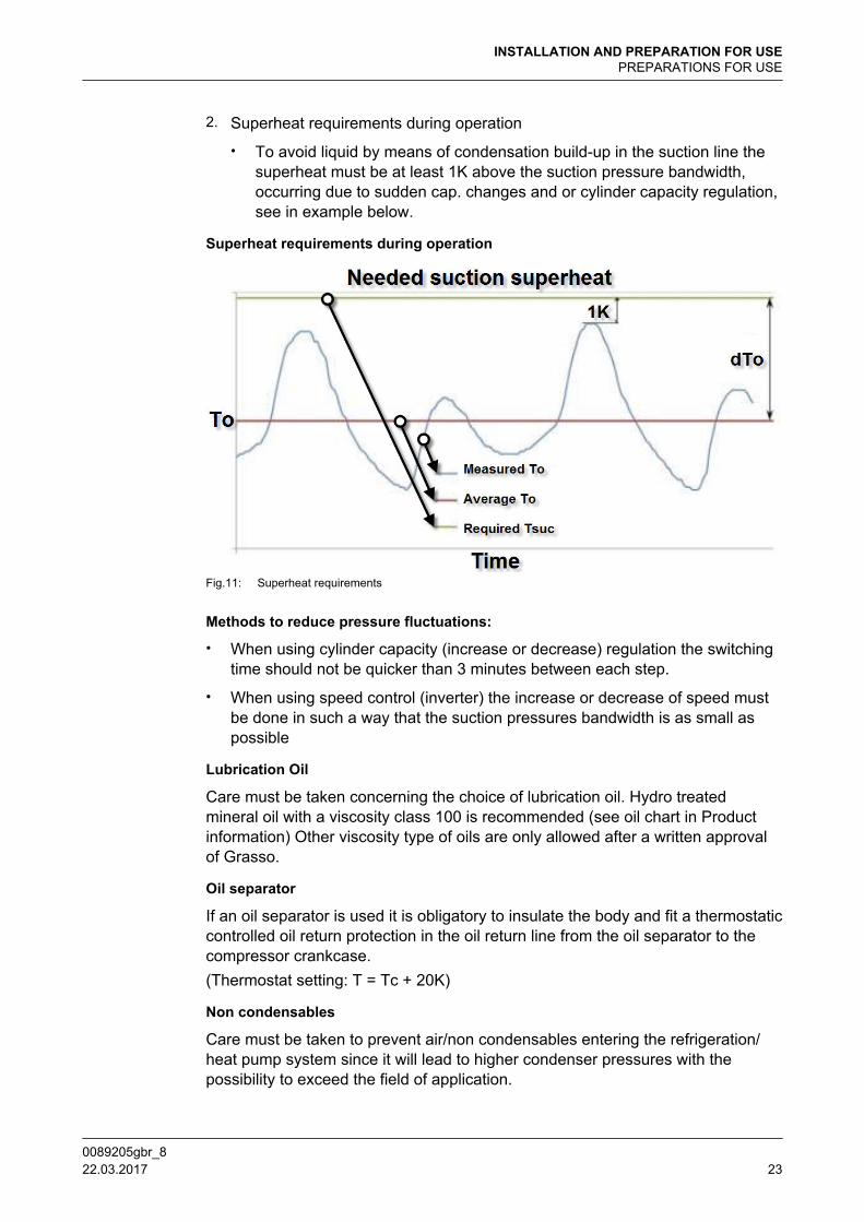
2. Superheat requirements during operation
• To avoid liquid by means of condensation build-up in the suction line thesuperheat must be at least 1K above the suction pressure bandwidth,occurring due to sudden cap. changes and or cylinder capacity regulation,see in example below.
Superheat requirements during operation
Fig.11: Superheat requirements
Methods to reduce pressure fluctuations:
• When using cylinder capacity (increase or decrease) regulation the switchingtime should not be quicker than 3 minutes between each step.
• When using speed control (inverter) the increase or decrease of speed mustbe done in such a way that the suction pressures bandwidth is as small aspossible
Lubrication Oil
Care must be taken concerning the choice of lubrication oil. Hydro treatedmineral oil with a viscosity class 100 is recommended (see oil chart in Productinformation) Other viscosity type of oils are only allowed after a written approvalof Grasso.
Oil separator
If an oil separator is used it is obligatory to insulate the body and fit a thermostaticcontrolled oil return protection in the oil return line from the oil separator to thecompressor crankcase.(Thermostat setting: T = Tc + 20K)
Non condensables
Care must be taken to prevent air/non condensables entering the refrigeration/heat pump system since it will lead to higher condenser pressures with thepossibility to exceed the field of application.
INSTALLATION AND PREPARATION FOR USEPREPARATIONS FOR USE
0089205gbr_8 22.03.2017 23
1.3.2 Leak test of compressor and system
The compressor (package) has been pressure tested prior to leaving the factory.In case an additional leak test is required, this test is should be carried out withdry nitrogen.
Hint!
DO NOT add oil to the compressor prior to pressure testing
A system leak test should be carried out over 24 hours to ensure that the systemis tightly sealed.Record during the pressure test, the pressure, ambient temperature and outsidetemperature. During the initial 6 hours a pressure drop of 2% is permissable. Withrespect to temperature variations, no further pressure loss should be detected inthe remaining 18 hours.
1.3.3 EVACUATION/DRYING THE REFRIGERATING SYSTEM
For evacuation of compressor only, refer to Section 2.5, Page 32
Procedure to evacuate and to dry a system:
i. STATUS: System is filled with nitrogen and no oil has been added (oilprevents any trapped moisture from boiling off).
ii. Verify that all valves in that part of the system to be evacuated are opened(refer also to the plant manual).
iii. Connect vacuum pump to the evacuation/purging valve(s) of the compressor(for location of these valves refer to the "Product Information" or to aconnection as mentioned in the plant manual and evacuate the system toapprox. 6 mBar.
iv. Break vacuum by charging dry nitrogen into the system.
v. Repeat step iii, "Connect vacuum pump ...".
vi. Wait approx. 24 hours.
vii. If pressure has increased (system still contains moisture), repeat steps iv, andvi. Otherwise, continue with the "Initial oil charge" procedure.
1.3.4 Initial oil charge
Hint!
Used or filtered oil should NEVER BE added to a compressor underany circumstance.Use only new oil as selected from the Grasso oil table, referSection 4.4, Page 49.Oil charging via the suction line of the compressor is not allowed.
Procedure:
i. STATUS: System is dried and still evacuated.
INSTALLATION AND PREPARATION FOR USEPREPARATIONS FOR USE
0089205gbr_824 22.03.2017

ii. Charge the oil separator (if present) initially with oil .
iii. Close suction and discharge stop valves of compressor and oil return line ofoil separator (if present).
iv. Charge the compressor crankcase with oil via the oil charge valve.
Warning Pre-lubrication just before the first start is obligatory.
QUANTITY OF OIL TO BE FILLED ( dm3)
Number ofcylinders
Shaft seal housing incl.internal circuit of crankshaft
Oil filters
Oil pum
p
Crankcase
Crankcase maxlevel - min level
3-4 0.71.5 0.5
19 4.7
5-6 0.8 23 5.7
1.3.5 Initial refrigerant charge
Refrigerant charging should be done in accordance with the plant manual byqualified refrigeration engineers.
1.3.6 Adjustment of instruments and safety devices
1.3.6.1 CONTROL DEVICES
Hint!
Refer to separate user manuals, in case an electrionic control deviceis installed.
1.3.6.2 Grasso 5HP
Pressure safety limit switches
Discharge pressureSetting 5 oC above design condensing
temp.
Precondition Max. = 51.0 bar(a)
Lubrication oil pressure difference Setting Min. =1.3 bar
Oil pressure regulators
Lubrication oil pressure difference1
Setting 2.0 bar
Precondition,at 50 oC oil temp.
Min. =1.3 barMax. =3.0 bar
1.3.6.3 Re-adjustment of oil pressure regulator
1 The oil pressure regulator is adjusted at the works, but it may occur that this setting should be correctedduring the initial run and also if the value <1.5 or >2.5 bar. The re-adjustment procedure is given in section“Re-adjustment of oil pressure regulator.
INSTALLATION AND PREPARATION FOR USEPREPARATIONS FOR USE
0089205gbr_8 22.03.2017 25
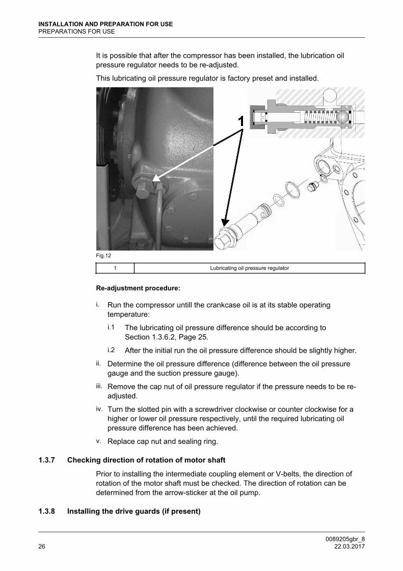
It is possible that after the compressor has been installed, the lubrication oilpressure regulator needs to be re-adjusted.
This lubricating oil pressure regulator is factory preset and installed.
Fig.12
1 Lubricating oil pressure regulator
Re-adjustment procedure:
i. Run the compressor untill the crankcase oil is at its stable operatingtemperature:
i.1 The lubricating oil pressure difference should be according toSection 1.3.6.2, Page 25.
i.2 After the initial run the oil pressure difference should be slightly higher.
ii. Determine the oil pressure difference (difference between the oil pressuregauge and the suction pressure gauge).
iii. Remove the cap nut of oil pressure regulator if the pressure needs to be re-adjusted.
iv. Turn the slotted pin with a screwdriver clockwise or counter clockwise for ahigher or lower oil pressure respectively, until the required lubricating oilpressure difference has been achieved.
v. Replace cap nut and sealing ring.
1.3.7 Checking direction of rotation of motor shaft
Prior to installing the intermediate coupling element or V-belts, the direction ofrotation of the motor shaft must be checked. The direction of rotation can bedetermined from the arrow-sticker at the oil pump.
1.3.8 Installing the drive guards (if present)
INSTALLATION AND PREPARATION FOR USEPREPARATIONS FOR USE
0089205gbr_826 22.03.2017

Only after the compressor is ready for the initial startup! Refer to the drive guardinstalling procedures included in the order documentation.
1.3.9 Initial oil warm up
Prior to the initial start-up, the crankcase heater (if present) must be energised.For the min. oil temperature refer to “Product Information (PI)“.
1.3.10 Initial start-up
1.3.10.1 Limitations of part load operation and start-up
The capacity control serves to adapt the compressor capacity at any moment asclosely as possible to the refrigerating capacity. In order to adjust the capacity, anumber of cylinders can be put in or out of action either individually or collectivelyby means of solenoid valves.
Warning
Due to start-up limitations and to limitations of part load operation itmay be that not all available part load steps are allowed under certainconditions. Use of incorrect control steps can damage compressorand/or components.
For a detailed description about start-up and part load limitations refer to thesoftware program “Comsel”.
1.3.10.2 Frequency controlled compressor
Hint!
In case of frequency controlled compressors, a separate instruction00.87.041 is required. If you don’t have this instruction consult Grasso.
1.3.10.3 Pre-start check list
The following Paragraph covers only the initial start of the compressor and notthe complete refrigeration plant.
Be sure that all necessary system valves are open and that the refrigerationsystem is ready for start up. Use the following check to guarantee that no items ofimportance regarding the compressor (package) have been overlooked.
i. System is charged with refrigerant.
ii. Settings of safety limit switches are adjusted properly.
iii. Direction of rotation of compressor crankshaft is correct.
iv. Check capacity control: Set the electrical capacity control switch to theposition of the lowest part load step.
v. Oil level established in sight glass.
vi. Stop valves to the pressure gauges are open.
INSTALLATION AND PREPARATION FOR USEPREPARATIONS FOR USE
0089205gbr_8 22.03.2017 27
vii. Suction stop valve is closed (in case the evaporating temperature is muchhigher than the design evaporating temperature) and the discharge stop valveis open.
viii.
Stop valve in the oil return line of the oil separator (if present) is closed.
When all items are verified, the compressor (package) is ready for the start-up.
1.3.11 Starting and stopping procedures
Hint!
For all limitations refer to "Main setup data"-overview! The values inthe main setup data tables, overrules the values as mentioned in thetext.
When starting the compressor a distinction should be made between:
1.3.11.1 First start
1. Notice "Pre-start check list", also consult the plant manual and verify thefollowing items:
– Check the oil temperature (refer to the "Product Information").
– Check crankcase oil level (refer to Section 2.4.1, Page 32).
2. Start the compressor and check whether the oil pressure increases.
Warning
The time interval between stopping and starting should be at least 2minutes and between starting and re-starting 10 minutes.
3. Slowly open suction stop valve and watch suction pressure, which may notexceed the max. value.
Warning
Refrigerant liquid hammer, will damage the compressor; Dry gas(superheat) is always necessary!
4. In case of electrically operated capacity control:One or more cylinders will be energized.
5. Watch maximum allowable motor current (refer to motor type plate).
6. Watch discharge temperature and max. allowable motor current (refer tomotor type plate).
7. Adjust pressure gauge stop valves, in order to avoid vibration of the pointers.(if present)
8. Open the stop valve in the oil return line from the oil separator (if present).
INSTALLATION AND PREPARATION FOR USEPREPARATIONS FOR USE
0089205gbr_828 22.03.2017
9. After 50 hours of operation retighten the coupling bolts or check and/orcorrect the tension of the V-belts and retighten the foundation bolts (with duerespect to the torque settings given by the supplier of the fasteners!).
1.3.11.2 Restart
Hint!
For the time interval between stopping and starting refer to "Mainsetup data"-overview.
Proceed to the complete starting procedure like “First start“
1.3.11.3 Restart after a short standstill period of time (less than 1 month)
• Refer to Section 1.3.11.2, Page 29.
1.3.11.4 Restart after a long standstill period of time
After a seasonal standstill (1 till 6 months) or maintenance operations;
Warning
After a standstill period of time more than 1 month, pre-lubrication justbefore starting is always obligatory. Refer Section 4.5, Page 49
• Check settings of control and safety equipment.
• Proceed to the complete starting procedure.
Warning
Restarting compressor after a standstill period of time more than 6months, consult your supplier. It is recommended to proceed with theinitial start up procedure.
1.3.11.5 Stopping the compressor
The compressor can be stopped at any moment, however, consult the supplier iffurther actions are required.
INSTALLATION AND PREPARATION FOR USE
0089205gbr_8 22.03.2017 29
2 INSPECTION AND TROUBLE SHOOTING
2.1 Periodical inspection
These inspections should be made during the normal shut-down periods as muchas possible, so the compressor is always ready to operate when required. If, atthat time, the number of running hours slightly differs from the scheduled periodbelow, the inspection should nevertheless be carried out.
In this way it will not be necessary to stop the compressor at inconvenient times.The frequency of inspections is dependent on the type of installation, operatingconditions and local regulations. In the case of automatically controlled plants,the periodical inspection are particularly important. The table below sums up allthe points on the compressor that have to be inspected or maintained along withinspection and maintenance frequencies.
2.2 Survey of periodical inspections
Apart from the check points in the table below, the sound produced by thecompressor also provides an indication of its mechanical condition. If abnormalsounds are audible, their cause should be traced and removed immediately inorder to prevent serious breakdowns.
INSPECTION AND TROUBLE SHOOTINGPeriodical inspection
0089205gbr_830 22.03.2017
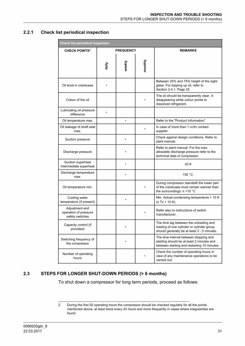
2.2.1 Check list periodical inspection
Check list periodical inspection
CHECK POINTS2 FREQUENCY REMARKS
daily
wee
kly
mon
thly
Oil level in crankcase • Between 25% and 75% height of the sightglass. For topping up oil, refer toSection 2.4.1, Page 32.
Colour of the oil •The oil should be transparently clear. Adisappearing white colour points todissolved refrigerant.
Lubricating oil pressuredifference •
Oil temperature max. • Refer to the "Product Information"
Oil leakage of shaft sealmax. • In case of more than 1 cc/hr contact
supplier.
Suction pressure • Check against design conditions. Refer toplant manual.
Discharge pressure • Refer to plant manual. For the max.allowable discharge pressure refer to thetechnical data of compressor.
Suction superheatIntermediate superheat • ≥0 K
Discharge temperaturemax. • 155 °C.
Oil temperature min. •During compressor standstill the lower partof the crankcase must remain warmer thanthe surroundings: ≥ +10 °C
Cooling watertemperature (if present) •
Min. Actual condensing temperature + 10 K(≥ Tc + 10 K)
Adjustment andoperation of pressure
safety switches • Refer also to instructions of switch
manufacturer.
Capacity control (ifprovided) •
The time lag between the unloading andloading of one cylinder or cylinder groupshould generally be at least 3 - 5 minutes.
Switching frequency ofthe compressor •
The time interval between stopping andstarting should be at least 2 minutes andbetween starting and restarting 10 minutes.
Number of operatinghours •
Check the number of operating hours inview of any maintenance operations to becarried out.
2.3 STEPS FOR LONGER SHUT-DOWN PERIODS (> 6 months)
To shut down a compressor for long term periods, proceed as follows:
2 During the first 50 operating hours the compressor should be checked regularly for all the pointsmentioned above, at least twice every 24 hours and more frequently in cases where irregularities arefound.
INSPECTION AND TROUBLE SHOOTINGSTEPS FOR LONGER SHUT-DOWN PERIODS (> 6 months)
0089205gbr_8 22.03.2017 31

i. Tightly shut both the suction and discharge stop valves and the stop valve ofthe oil return line (if present).
ii. Disconnect the power source from the compressor drive motor and theelectrical control cabinet.
iii. Place a moisture absorbing compound (eg a dessicant such as silica gel)inside the control cabinet.
iv. Place warning tags on the electric system and all closed stop valves.
Prior to starting up after a shut down, change the oil and exchange the oil filters.Determine the starting and stopping procedure from prior to start the compressor.
2.4 LUBRICATION DATA
Determine max Toil and set this value in the safety device.Change the oil as soon as an oil analysis indicates contaminated oil.
Warning
It is expressly pointed out that it is not permitted to mix different typesof oil. If another type of oil is used, first remove all the stale oil in thefilters, oil pump, crankcase, shaft seal, oil separator and oil drains ofthe installation.
2.4.1 Topping up oil with compressor operating
Hint!
Use Grasso’s hand-operated oil pump, part. no. 18.13.121
Topping up oil is permitted during compressor operation.
Be sure that this oil is the same as in the plant (refer to Section 2.4, Page 32).
Without affecting the operation of the compressor, the oil may be topped up bymeans of a separate oil pump. This pump enables the oil to be forced into thecrankcase via the oil charging valve, against suction pressure.
Fig.13: Oil level in compressor sight glass
2.5 EVACUATION, LEAK TESTING AND START-UP OF THE COMPRESSOR/PACKAGETo evacuate the refrigeration system refer to Section 1.3.3, Page 24,
INSPECTION AND TROUBLE SHOOTINGLUBRICATION DATA
0089205gbr_832 22.03.2017
Always use a vacuum pump or pump-down unit to evacuate the refrigerant fromthe compressor.
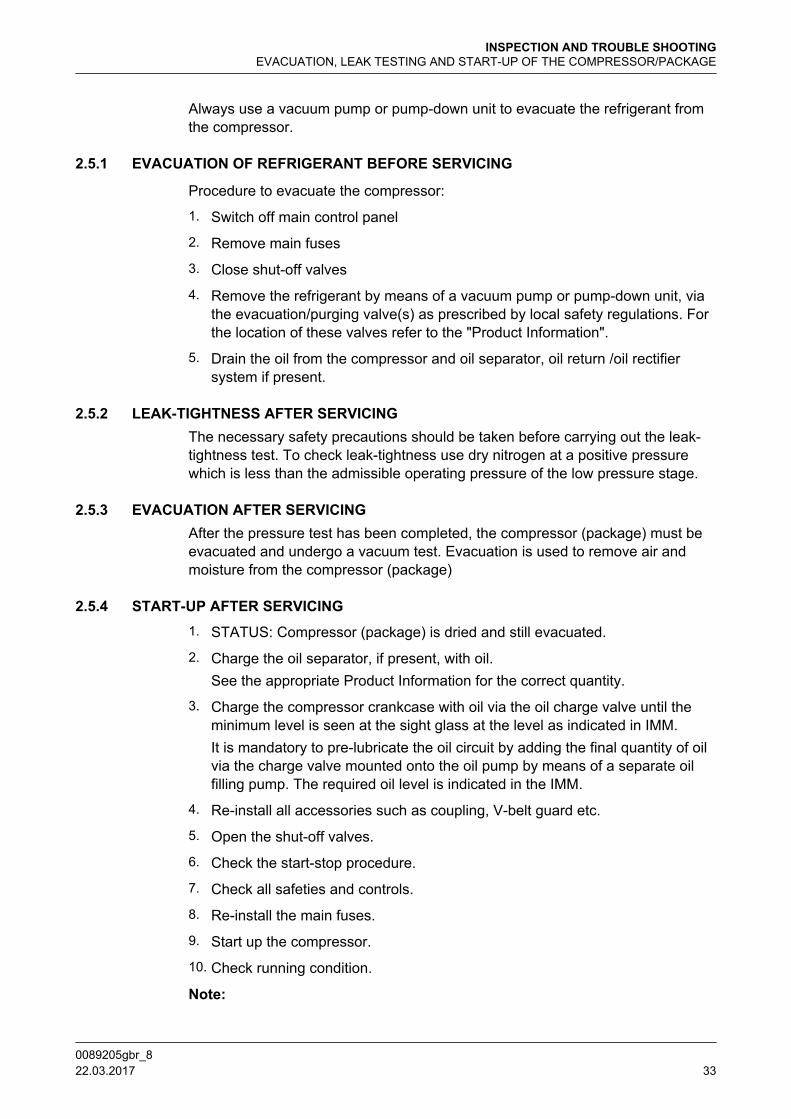
2.5.1 EVACUATION OF REFRIGERANT BEFORE SERVICING
Procedure to evacuate the compressor:
1. Switch off main control panel
2. Remove main fuses
3. Close shut-off valves
4. Remove the refrigerant by means of a vacuum pump or pump-down unit, viathe evacuation/purging valve(s) as prescribed by local safety regulations. Forthe location of these valves refer to the "Product Information".
5. Drain the oil from the compressor and oil separator, oil return /oil rectifiersystem if present.
2.5.2 LEAK-TIGHTNESS AFTER SERVICINGThe necessary safety precautions should be taken before carrying out the leak-tightness test. To check leak-tightness use dry nitrogen at a positive pressurewhich is less than the admissible operating pressure of the low pressure stage.
2.5.3 EVACUATION AFTER SERVICINGAfter the pressure test has been completed, the compressor (package) must beevacuated and undergo a vacuum test. Evacuation is used to remove air andmoisture from the compressor (package)
2.5.4 START-UP AFTER SERVICING1. STATUS: Compressor (package) is dried and still evacuated.
2. Charge the oil separator, if present, with oil.See the appropriate Product Information for the correct quantity.
3. Charge the compressor crankcase with oil via the oil charge valve until theminimum level is seen at the sight glass at the level as indicated in IMM.It is mandatory to pre-lubricate the oil circuit by adding the final quantity of oilvia the charge valve mounted onto the oil pump by means of a separate oilfilling pump. The required oil level is indicated in the IMM.
4. Re-install all accessories such as coupling, V-belt guard etc.
5. Open the shut-off valves.
6. Check the start-stop procedure.
7. Check all safeties and controls.
8. Re-install the main fuses.
9. Start up the compressor.
10. Check running condition.
Note:
INSPECTION AND TROUBLE SHOOTINGEVACUATION, LEAK TESTING AND START-UP OF THE COMPRESSOR/PACKAGE
0089205gbr_8 22.03.2017 33

The job isn't finished until the paper work is done! Complete the service report,e.g. Grasso report 00.89.062.
2.6 DRAINING AND CHANGE OF OIL
To top up oil see Section 2.4.1, Page 32, Oil changing procedure:
i. Evacuate the compressor (refer to Section 2.5, Page 32).
ii. Drain the oil via the oil charging/drain valve. Remove the cover of one or moreservice openings on the compressor side.
iii. Clean the inside of the crankcase with a non-fibrous cloth (do not use cottonwaste!).
iv. Replace the service cover(s) with a new seal.
v. Charge crankcase with clean oil in accordance with the procedure.
2.7 Oil discharge filter
Hint!
An oil discharge (running-in) filter is factory mounted. This filter mustbe exchanged after max. 100 running hours. Oil filters can not becleaned!
Replace this filter according to the schedule in Section 2.2.2 and to thereplacement instructions included in the filter set (GREY = permanent) or in caseof a modified plant (RED = running-in).
2.8 OIL SUCTION AND DISCHARGE FILTERS
Schedule
Replace these filters according to the Service Maintenance Schedules.The frequency of exchanging these filters depends on the conditions of therefrigeration system.
Hint!
It is recommended to exchange these filters when the compressor isoverhauled or when pressure drop exceeds 1.0 bar.
2.9 REPLACEMENT OF SUCTION GAS FILTER(S)
Hint!
Running-in suction gas filter(s) is(are) factory mounted. This(these)filter(s) must be exchanged after max. 100 running hours. Running-infilters can not be cleaned!
Procedure:
i. Evacuate the compressor.
ii. Remove and exchange the suction gas filter(s).
INSPECTION AND TROUBLE SHOOTINGDRAINING AND CHANGE OF OIL
0089205gbr_834 22.03.2017

iii. Purge the compressor.
2.10 DISMANTLING, INSPECTION AND RE-ASSEMBLY OF SUCTION AND DISCHARGEVALVES
Hint!
A high working temperature and rapid temperature variations shortenthe life time of the valves, which, for this reason, require regularinspection.
The suction and discharge valves of a refrigeration compressor are parts that areheavily loaded both mechanically and thermally. Wear and life time of the valvesstrongly depend on the working conditions of the compressor. It is recommendedthat valve condition is regularly checked.For dismantling, inspection and re-assembly of the valves, refer to the relevant paragraph of the CompressorService Instruction Manual.
Hint!
In order to reduce the downtime involved in the valve inspection, it isrecommended to have as many complete valve assemblies in stock asthere are cylinders on the compressor.These valves can be exchangedwith the original valves; in this case, these original valves can beinspected and repaired or replaced if necessary later.
2.11 COMPRESSOR PURGING
Procedure to purge the compressor (after maintenance jobs):
STATUS:
Stop valves of suction, discharge and oil return line are still closed (refer toSection 2.5, Page 32) and compressor is filled with oil (refer to Section 2.6,Page 34).
i. Connect a vacuum pump to the evacuation/purging valve(s) and evacuate asprescribed by local regulations. For the location of these valves refer to the"Product Information".
ii. When evacuation is completed open the discharge stop valve.
iii. Watch suction and discharge pressure.
Hint!
If suction pressure increases quickly, the discharge valve assy isleaking.
iv. Start compressor.
v. Slowly open suction stop valve.
vi. Open the stop valve in the oil return line of the oil separator (if present).
vii. For two stage compressor only;
INSPECTION AND TROUBLE SHOOTINGDISMANTLING, INSPECTION AND RE-ASSEMBLY OF SUCTION AND DISCHARGE VALVES
0089205gbr_8 22.03.2017 35
vii.a Two-stage system A/B: open liquid supply to interstage cooler.
vii.b Two-stage system C/D: refer to the plant manual.
viii.
If a Self-Limiting Automatic Purger is not installed, purge the refrigeratingsystem (refer to the plant manual).
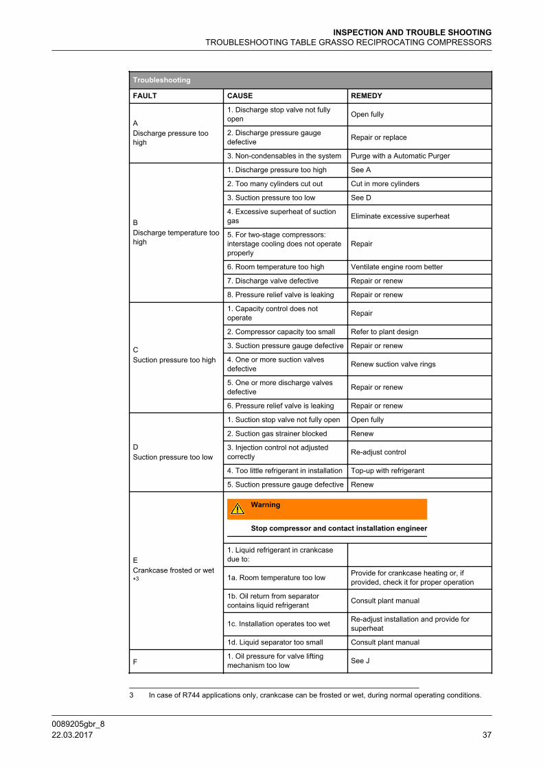
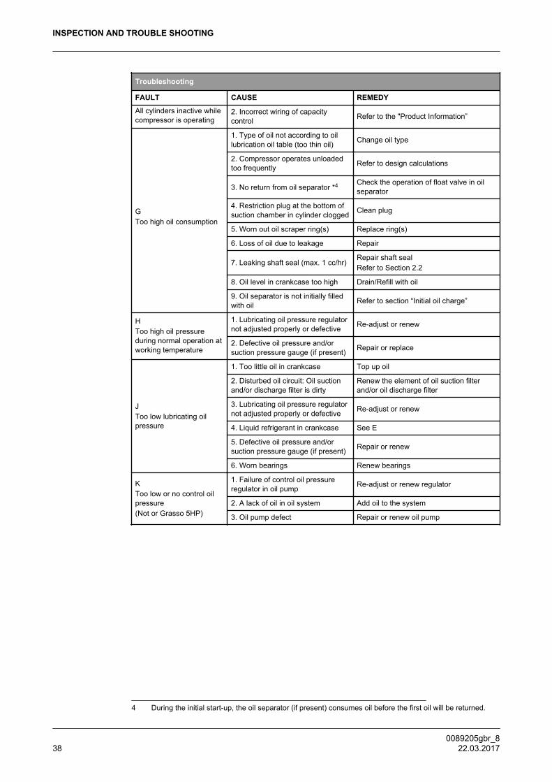
2.12 TROUBLESHOOTING TABLE GRASSO RECIPROCATING COMPRESSORS
The troubleshooting table shown overleaf may be helpful to quickly trace andremedy failures that interfere with the proper operation of the compressor. It isemphatically pointed out that the cause of a failure must often be sought in therefrigeration installation itself. Therefore, it is necessary besides this table also toconsult the plant manual.
INSPECTION AND TROUBLE SHOOTINGTROUBLESHOOTING TABLE GRASSO RECIPROCATING COMPRESSORS
0089205gbr_836 22.03.2017
Troubleshooting
FAULT CAUSE REMEDY
ADischarge pressure toohigh
1. Discharge stop valve not fullyopen Open fully
2. Discharge pressure gaugedefective Repair or replace
3. Non-condensables in the system Purge with a Automatic Purger
BDischarge temperature toohigh
1. Discharge pressure too high See A
2. Too many cylinders cut out Cut in more cylinders
3. Suction pressure too low See D
4. Excessive superheat of suctiongas Eliminate excessive superheat
5. For two-stage compressors:interstage cooling does not operateproperly
Repair
6. Room temperature too high Ventilate engine room better
7. Discharge valve defective Repair or renew
8. Pressure relief valve is leaking Repair or renew
CSuction pressure too high
1. Capacity control does notoperate Repair
2. Compressor capacity too small Refer to plant design
3. Suction pressure gauge defective Repair or renew
4. One or more suction valvesdefective Renew suction valve rings
5. One or more discharge valvesdefective Repair or renew
6. Pressure relief valve is leaking Repair or renew
DSuction pressure too low
1. Suction stop valve not fully open Open fully
2. Suction gas strainer blocked Renew
3. Injection control not adjustedcorrectly Re-adjust control
4. Too little refrigerant in installation Top-up with refrigerant
5. Suction pressure gauge defective Renew
ECrankcase frosted or wet*3
Warning
Stop compressor and contact installation engineer
1. Liquid refrigerant in crankcasedue to:
1a. Room temperature too low Provide for crankcase heating or, ifprovided, check it for proper operation
1b. Oil return from separatorcontains liquid refrigerant Consult plant manual
1c. Installation operates too wet Re-adjust installation and provide forsuperheat
1d. Liquid separator too small Consult plant manual
F1. Oil pressure for valve liftingmechanism too low See J
3 In case of R744 applications only, crankcase can be frosted or wet, during normal operating conditions.
INSPECTION AND TROUBLE SHOOTINGTROUBLESHOOTING TABLE GRASSO RECIPROCATING COMPRESSORS
0089205gbr_8 22.03.2017 37
Troubleshooting
FAULT CAUSE REMEDY
All cylinders inactive whilecompressor is operating
2. Incorrect wiring of capacitycontrol Refer to the "Product Information”
GToo high oil consumption
1. Type of oil not according to oillubrication oil table (too thin oil) Change oil type
2. Compressor operates unloadedtoo frequently Refer to design calculations
3. No return from oil separator *4 Check the operation of float valve in oilseparator
4. Restriction plug at the bottom ofsuction chamber in cylinder clogged Clean plug
5. Worn out oil scraper ring(s) Replace ring(s)
6. Loss of oil due to leakage Repair
7. Leaking shaft seal (max. 1 cc/hr)Repair shaft sealRefer to Section 2.2
8. Oil level in crankcase too high Drain/Refill with oil
9. Oil separator is not initially filledwith oil Refer to section “Initial oil charge”
HToo high oil pressureduring normal operation atworking temperature
1. Lubricating oil pressure regulatornot adjusted properly or defective Re-adjust or renew
2. Defective oil pressure and/orsuction pressure gauge (if present) Repair or replace
JToo low lubricating oilpressure
1. Too little oil in crankcase Top up oil
2. Disturbed oil circuit: Oil suctionand/or discharge filter is dirty
Renew the element of oil suction filterand/or oil discharge filter
3. Lubricating oil pressure regulatornot adjusted properly or defective Re-adjust or renew
4. Liquid refrigerant in crankcase See E
5. Defective oil pressure and/orsuction pressure gauge (if present) Repair or renew
6. Worn bearings Renew bearings
KToo low or no control oilpressure(Not or Grasso 5HP)
1. Failure of control oil pressureregulator in oil pump Re-adjust or renew regulator
2. A lack of oil in oil system Add oil to the system
3. Oil pump defect Repair or renew oil pump
4 During the initial start-up, the oil separator (if present) consumes oil before the first oil will be returned.
INSPECTION AND TROUBLE SHOOTING
0089205gbr_838 22.03.2017
3 MAINTENANCE
3.1 Spare parts manual
Hint!
A complete spare parts overview is available as a separate manual.Download the parts list manual via internet (DocNav) or consultGrasso.
3.2 Post start-up maintenance
After the compressor has run for the initial 100 operating hours:
i. Drain the oil and refill the compressor with the correct amount of fresh oil.
ii. Replace the running oil discharge filter element with the “permanent“ filterelement in accordance with the filter replacement instructions.
iii. Inspect suction gas filter (refer to the Compressor Service InstructionManual).
iv. Exchange or clean oil suction filter element.
v. Check the compressor shaft seal for leakage. If excessive (more than 1 cc/hr)replace the seal.
vi. 1) Retighten the coupling mounting bolts with the torque settings as given bythe coupling manufacturer.2) Verify and if necessary, correct the tension of the V-belts as given in theGrasso instruction 0087516.
vii. Verify and if necessary, correct the torque settings of all foundation bolts asgiven in Compressor Service Instruction Manual.
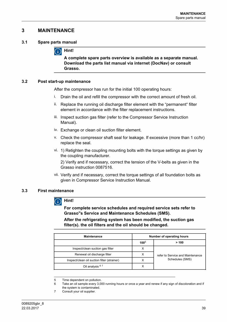
3.3 First maintenance
Hint!
For complete service schedules and required service sets refer toGrasso"s Service and Maintenance Schedules (SMS).After the refrigerating system has been modified, the suction gasfilter(s). the oil filters and the oil should be changed.
Maintenance Number of operating hours
1005 > 100
Inspect/clean suction gas filter X
refer to Service and MaintenanceSchedules (SMS)
Renewal oil discharge filter X
Inspect/clean oil suction filter (strainer) X
Oil analysis 6 7 X
5 Time dependent on pollution.6 Take an oil sample every 3,000 running hours or once a year and renew if any sign of discoloration and if
the system is contaminated.7 Consult your oil supplier.
MAINTENANCESpare parts manual
0089205gbr_8 22.03.2017 39

3.4 Legend
Warning
These operations cover routine maintenance and are meant as a guideonly. Lack of maintenance, frequency of stop/starting, extremeoperating conditions etc could lead to accelerated wear.
General;
The service and maintenance schedules use the codes as explained in the tablebelow;
Actions
Legend for service and maintenance schedules (SMS)
Item Code/Actions Description
1 IC Inspection / Alternatively renewal - correcting / Testing
2 IV Inspection Visual / Alternatively electrical testing
3 RE Renewal
4 ME Measure
5 CL Clean
3.4.1 SMS Grasso 5HP
Hint!
Consult Grasso to determine the service interval and the servicemaintenance
3.4.2 Checklist
Service and maintenance schedules Grasso RECIPROCATING COMPRESSORS
Item Description Checked/Remarks/Notes Checkpoint/Setting/Value
A Compressor type
B Machine number
C Date
D Running hours
E Refrigerant
E Evaporating temperature/pressure To/Po
F Intermediate temperature/pressure Tm/Pm
G Discharge temperature/pressure Tc/Pc
H Oil lubricating pressure
I Oil control pressure
J GeneralNotes
MAINTENANCELegend
0089205gbr_840 22.03.2017
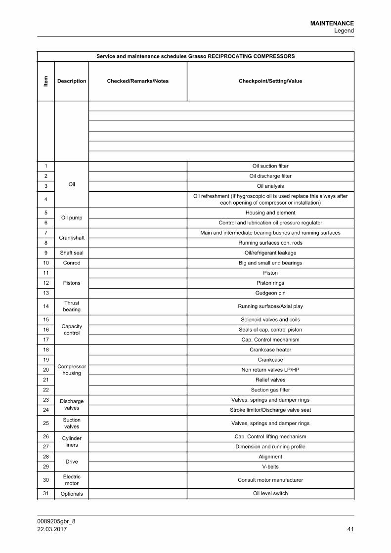
Service and maintenance schedules Grasso RECIPROCATING COMPRESSORS
Item Description Checked/Remarks/Notes Checkpoint/Setting/Value
1
Oil
Oil suction filter
2 Oil discharge filter
3 Oil analysis
4 Oil refreshment (If hygroscopic oil is used replace this always aftereach opening of compressor or installation)
5Oil pump
Housing and element
6 Control and lubrication oil pressure regulator
7Crankshaft
Main and intermediate bearing bushes and running surfaces
8 Running surfaces con. rods
9 Shaft seal Oil/refrigerant leakage
10 Conrod Big and small end bearings
11
Pistons
Piston
12 Piston rings
13 Gudgeon pin
14 Thrustbearing Running surfaces/Axial play
15Capacitycontrol
Solenoid valves and coils
16 Seals of cap. control piston
17 Cap. Control mechanism
18
Compressorhousing
Crankcase heater
19 Crankcase
20 Non return valves LP/HP
21 Relief valves
22 Suction gas filter
23 Dischargevalves
Valves, springs and damper rings
24 Stroke limitor/Discharge valve seat
25 Suctionvalves Valves, springs and damper rings
26 Cylinderliners
Cap. Control lifting mechanism
27 Dimension and running profile
28Drive
Alignment
29 V-belts
30 Electricmotor Consult motor manufacturer
31 Optionals Oil level switch
MAINTENANCELegend
0089205gbr_8 22.03.2017 41

Service and maintenance schedules Grasso RECIPROCATING COMPRESSORS
Item Description Checked/Remarks/Notes Checkpoint/Setting/Value
32 Safety switches
33 Gauges
34 Thermostats
35 Thermometers
36 Electrical control system
37 Valve oil return protection
38 Thermistors
39 Vibration dampers and bolts
40 Intermediate cooler and injection valve
41 Oil separator refreshing oil and cleaning/testing of float valve
42 Heavy duty thrust bearing
43 Oil cooler, air side
44 Oil cooler, oil side, refrigeration oil
45 Consult motor manufacturer Oil cooler, electric motor (fan)
46 Cylinder head water cooling system
Settings pressure safeties
Safety Remark Value
1 Suction pressure
2 LP discharge pressure (safety) two stage only
3 LP discharge pressure (limitor) two stage only,TUV
4 High pressure suction (safety) two stage only
5 High pressure (safety)
6 High pressure (limitor) TUV only
7 OIl differential pressure
MAINTENANCELegend
0089205gbr_842 22.03.2017

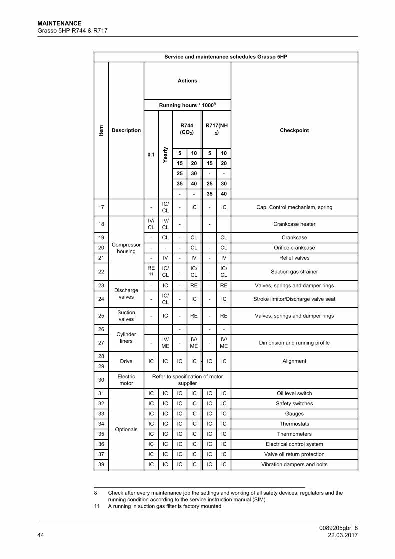
3.5 Grasso 5HP R744 & R717
Service and maintenance schedules Grasso 5HP
Item Description
Actions
Checkpoint
Running hours * 10008
0.1Ye
arly
R744(CO2)
R717(NH3)
5 10 5 10
15 20 15 20
25 30 - -
35 40 25 30
- - 35 40
1
Oil
CL CL CL CL CL CL Oil suction strainer
2RE
9 RE RE RE RE RE Oil discharge filter10
3 - ME ME ME ME ME Oil analysis
4 RE RE - RE - REOil refreshment (If hygroscopical oil is used replace
this always after each opening of compressor orinstallation)
5Oil pump
- IC/CL - IC/
CL - IC/CL Housing and element
6 - IC/CL - IC/
CL - IC/CL Control and lubrication oil pressure regulator
7a
Crankshaft
- - - IC/ME - IC/
ME Main bearing bushes
7b - - - IC/ME - IC/
ME Main bearing surfaces crankshaft
8 - IC/ME - IC/
ME - IC/ME Running surfaces con. rods
9 Shaft seal - IC IC IC IC IC Oil/refrigerant leakage
10 Conrod - IC/ME - IC/
ME - IC/ME Big and small end bearings
11
Pistons
- IC - IC - IC Piston
12 - IC - IC - IC Piston rings
13 - - - IC - IC Gudgeon pin
14 Thrustbearing - IV - IV - IV Running surfaces
15 Capacitycontrol
IC/IV
IC/IV
-RE
-RE Solenoid valves and coils
16 - -
8 Check after every maintenance job the settings and working of all safety devices, regulators and therunning condition according to the service instruction manual (SIM)
9 A running in oil discharge filter is factory mounted10 The permanent oil discharge filter has to be changed every 5000 hours or check (optional) oil differential
pressure indicator
MAINTENANCEGrasso 5HP R744 & R717
0089205gbr_8 22.03.2017 43
Service and maintenance schedules Grasso 5HP
Item Description
Actions
Checkpoint
Running hours * 10008
0.1
Year
ly
R744(CO2)
R717(NH3)
5 10 5 10
15 20 15 20
25 30 - -
35 40 25 30
- - 35 40
17 - IC/CL - IC - IC Cap. Control mechanism, spring
18
Compressorhousing
IV/CL
IV/CL - - Crankcase heater
19 - CL - CL - CL Crankcase
20 - - - CL - CL Orifice crankcase
21 - IV - IV - IV Relief valves
22RE11
IC/CL - IC/
CL - IC/CL Suction gas strainer
23Discharge
valves
- IC - RE - RE Valves, springs and damper rings
24 - IC/CL - IC - IC Stroke limitor/Discharge valve seat
25 Suctionvalves - IC - RE - RE Valves, springs and damper rings
26Cylinder
liners
- - -
27 - IV/ME - IV/
ME - IV/ME Dimension and running profile
28Drive IC IC IC IC IC IC Alignment
29
30 Electricmotor
Refer to specification of motorsupplier
31
Optionals
IC IC IC IC IC IC Oil level switch
32 IC IC IC IC IC IC Safety switches
33 IC IC IC IC IC IC Gauges
34 IC IC IC IC IC IC Thermostats
35 IC IC IC IC IC IC Thermometers
36 IC IC IC IC IC IC Electrical control system
37 IC IC IC IC IC IC Valve oil return protection
39 IC IC IC IC IC IC Vibration dampers and bolts
8 Check after every maintenance job the settings and working of all safety devices, regulators and therunning condition according to the service instruction manual (SIM)
11 A running in suction gas filter is factory mounted
MAINTENANCEGrasso 5HP R744 & R717
0089205gbr_844 22.03.2017
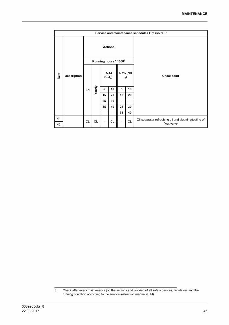
Service and maintenance schedules Grasso 5HP
Item Description
Actions
Checkpoint
Running hours * 10008
0.1
Year
ly
R744(CO2)
R717(NH3)
5 10 5 10
15 20 15 20
25 30 - -
35 40 25 30
- - 35 40
41CL CL - CL - CL Oil separator refreshing oil and cleaning/testing of
float valve42
8 Check after every maintenance job the settings and working of all safety devices, regulators and therunning condition according to the service instruction manual (SIM)
MAINTENANCE
0089205gbr_8 22.03.2017 45
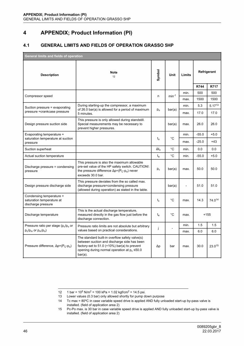
4 APPENDIX; Product Information (PI)
4.1 GENERAL LIMITS AND FIELDS OF OPERATION GRASSO 5HP
General limits and fields of operation
DescriptionNote
12
Sym
bol
Unit LimitsRefrigerant
R744 R717
Compressor speed n min-1min. 500 500
max. 1500 1500
Suction pressure = evaporatingpressure =crankcase pressure
During starting-up the compressor, a maximumof 26.0 bar(a) is allowed for a period of maximum5 minutes.
po bar(a)min. 5.3 5.1713
max. 17.0 17.0
Design pressure suction sideThis pressure is only allowed during standstill.Special measurements may be necessary toprevent higher pressures.
bar(a) max. 26.0 26.0
Evaporating temperature =saturation temperature at suctionpressure
to °Cmin. -55.0 +5.0
max. -25.0 +43
Suction superheat Δto °C min. 0.0 0.0
Actual suction temperature ta °C min. -55.0 +5.0
Discharge pressure = condensingpressure
This pressure is also the maximum allowablepre-set value of the HP safety switch. CAUTION!:the pressure difference Δp=(PC-po) neverexceeds 30.0 bar.
pc bar(a) max. 50.0 50.0
Design pressure discharge sideThis pressure deviates from the so called max.discharge pressure=condensing pressure(allowed during operation) as stated in the table.
bar(a) - 51.0 51.0
Condensing temperature =saturation temperature atdischarge pressure
tc °C max. 14.3 74.014
Discharge temperatureThis is the actual discharge temperature,measured directly in the gas flow just before thedischarge connection.
te °C max. +155
Pressure ratio per stage (pc/po orpc/pm or pm/po)
Pressure ratio limits are not absolute but arbitraryvalues based on practical considerations. j -
min. 1.5 1.5
max. 6.0 6.0
Pressure difference, Δp=(PC-po)
The standard built-in overflow safety valve(s)between suction and discharge side has beenfactory-set to 51.0 (+10%) bar(a) to preventopening during normal operation at pc ≤50.0bar(a).
Δp bar max. 30.0 23.015
12 1 bar = 105 N/m2 = 100 kPa = 1.02 kgf/cm2 = 14.5 psi.13 Lower values (0.3 bar) only allowed shortly for pump down purpose14 Tc max = 80oC in case variable speed drive is applied AND fully unloaded start-up by-pass valve is
installed. (field of application area 2)15 Pc-Po max. is 30 bar in case variable speed drive is applied AND fully unloaded start-up by-pass valve is
installed. (field of application area 2)
APPENDIX; Product Information (PI)GENERAL LIMITS AND FIELDS OF OPERATION GRASSO 5HP
0089205gbr_846 22.03.2017
General limits and fields of operation
DescriptionNote
12
Sym
bol
Unit LimitsRefrigerant
R744 R717
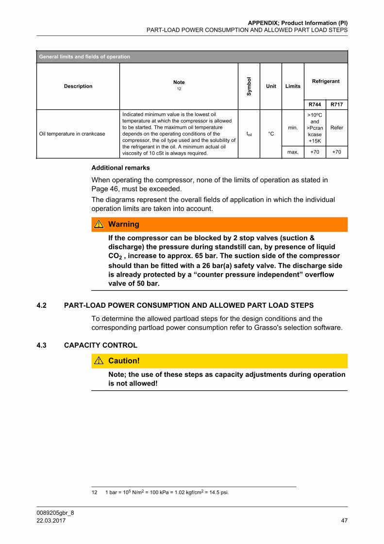
Oil temperature in crankcase
Indicated minimum value is the lowest oiltemperature at which the compressor is allowedto be started. The maximum oil temperaturedepends on the operating conditions of thecompressor, the oil type used and the solubility ofthe refrigerant in the oil. A minimum actual oilviscosity of 10 cSt is always required.
toil °Cmin.
>10oCand
>Pcrankcase+15K
Refer
max. +70 +70
Additional remarks
When operating the compressor, none of the limits of operation as stated inPage 46, must be exceeded.The diagrams represent the overall fields of application in which the individualoperation limits are taken into account.
Warning
If the compressor can be blocked by 2 stop valves (suction &discharge) the pressure during standstill can, by presence of liquidCO2 , increase to approx. 65 bar. The suction side of the compressorshould than be fitted with a 26 bar(a) safety valve. The discharge sideis already protected by a “counter pressure independent” overflowvalve of 50 bar.
4.2 PART-LOAD POWER CONSUMPTION AND ALLOWED PART LOAD STEPS
To determine the allowed partload steps for the design conditions and thecorresponding partload power consumption refer to Grasso's selection software.
4.3 CAPACITY CONTROL
Caution!
Note; the use of these steps as capacity adjustments during operationis not allowed!
12 1 bar = 105 N/m2 = 100 kPa = 1.02 kgf/cm2 = 14.5 psi.
APPENDIX; Product Information (PI)PART-LOAD POWER CONSUMPTION AND ALLOWED PART LOAD STEPS
0089205gbr_8 22.03.2017 47
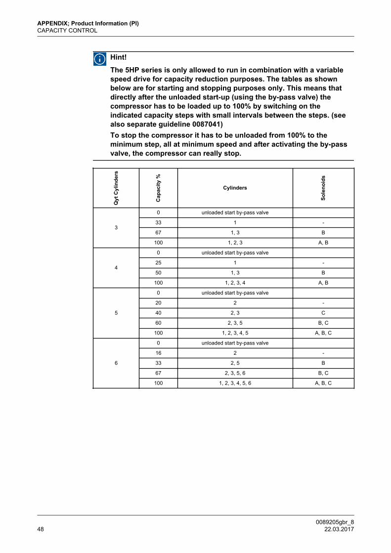
Hint!
The 5HP series is only allowed to run in combination with a variablespeed drive for capacity reduction purposes. The tables as shownbelow are for starting and stopping purposes only. This means thatdirectly after the unloaded start-up (using the by-pass valve) thecompressor has to be loaded up to 100% by switching on theindicated capacity steps with small intervals between the steps. (seealso separate guideline 0087041)To stop the compressor it has to be unloaded from 100% to theminimum step, all at minimum speed and after activating the by-passvalve, the compressor can really stop.
Qyt
Cyl
inde
rs
Cap
acity
%
Cylinders
Sole
noid
s
3
0 unloaded start by-pass valve 33 1 -
67 1, 3 B
100 1, 2, 3 A, B
4
0 unloaded start by-pass valve 25 1 -
50 1, 3 B
100 1, 2, 3, 4 A, B
5
0 unloaded start by-pass valve 20 2 -
40 2, 3 C
60 2, 3, 5 B, C
100 1, 2, 3, 4, 5 A, B, C
6
0 unloaded start by-pass valve 16 2 -
33 2, 5 B
67 2, 3, 5, 6 B, C
100 1, 2, 3, 4, 5, 6 A, B, C
APPENDIX; Product Information (PI)CAPACITY CONTROL
0089205gbr_848 22.03.2017

4.4 LUBRICATING OILS (choice and recommendations Grasso HP)
For lubrication of refrigeration compressors, several brands and types of speciallydeveloped lubricating oils are on the market. The choice of oil depends not onlyon its good lubrication properties (viscosity) and chemical stability at theoperating conditions of the compressor, but also on the operating conditions ofthe refrigerating plant (solidifying and floc point, solubility).
Grasso has tested and approved for use in its reciprocating-compressors thebrands and types of oil as listed in table below.The choice of the lubricating oil depends on the operating conditions of thecompressor and refrigerant.The oil viscosity should always be more than 10 cSt. Assumed is that the oiltemperature at the bearing surfaces = 15 K above crankcase oil temperature.
Remark
In contradiction with a normal refrigeration a plant, using NH3 as refrigerant, aheat pump application running on NH3 needs a viscosity class ISO VG100 wherein the normal refrigeration plant ISO VG68 type of oil will do. The reason for usinga thicker oil is that at higher suction pressures a higher concentration ofrefrigerant solves in the oil resulting in reduced viscosity.Find in the table below the oil(s) to be used for the application
Hint!
Some oil types may be marketed under other names and/ordesignations; these oils can also be used, provided their identity canbe proved beyond any doubt. Application of other/alternavive oils isnot permitted without the written consent of Grasso.
Accepted oil types
Brand Type designation Refrigerant Food Grade
Fuchs Reniso C85E R744 (CO2) -
CPI CP-1009-100R717 (NH3)
Heat pump appications-
For all other oils consult Grasso
4.5 Pre-lubrication oil system
Why pre-lubrication?
Pre-lubrication is necessary in situations listed below, in order to providesufficient lubricating oil at locations where this is most needed (oil pump,bearings, pistons en piston rings) to ensure that any risk on 'dry running' isminimized or even better eliminated. Dry-running of oil pump bearings pistonsand piston rings will initiate and after initiation worsen the wear of the partsmentioned and eventually even damage the crank shaft and cylinder liners oreven more parts.
When pre-lubrication?
1. Before initial start-up
APPENDIX; Product Information (PI)LUBRICATING OILS (choice and recommendations Grasso HP)
0089205gbr_8 22.03.2017 49
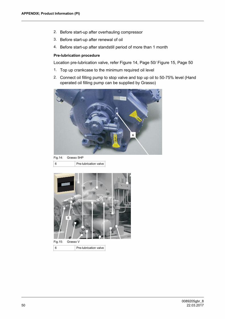
2. Before start-up after overhauling compressor
3. Before start-up after renewal of oil
4. Before start-up after standstill period of more than 1 month
Pre-lubrication procedure
Location pre-lubrication valve, refer Figure 14, Page 50/ Figure 15, Page 50
1. Top up crankcase to the minimum required oil level
2. Connect oil filling pump to stop valve and top up oil to 50-75% level (Handoperated oil filling pump can be supplied by Grasso)
Fig.14: Grasso 5HP
6 Pre-lubrication valve
Fig.15: Grasso V
6 Pre-lubrication valve
APPENDIX; Product Information (PI)
0089205gbr_850 22.03.2017

APPENDIX; Product Information (PI)
0089205gbr_8 22.03.2017 51

GEA Group is a global engineering company with multi-billion euro sales and operations in more than 50 countries. Founded in 1881, the company is one of the largest providers of innovative equipment and process technology. GEA Group is listed in the STOXX® Europe 600 Index.
We live our values.Excellence • Passion • Integrity • Responsibility • GEA-versity
GEA RefrigerationGEA Refrigeration Netherlands N.V.Parallelweg 255223 AL ‘s-Hertogenbosch,Netherlands
Phone +31 (0)73 6203 911
[email protected] gea.com