GEA Grasso V refrigeration Reciprocating Compressors for ... Documents/Grasso...The compressor...
62
Reciprocating Compressors for industrial refrigeration GEA Grasso V Installation and Maintenance instructions 0089288gbr_11
Transcript of GEA Grasso V refrigeration Reciprocating Compressors for ... Documents/Grasso...The compressor...
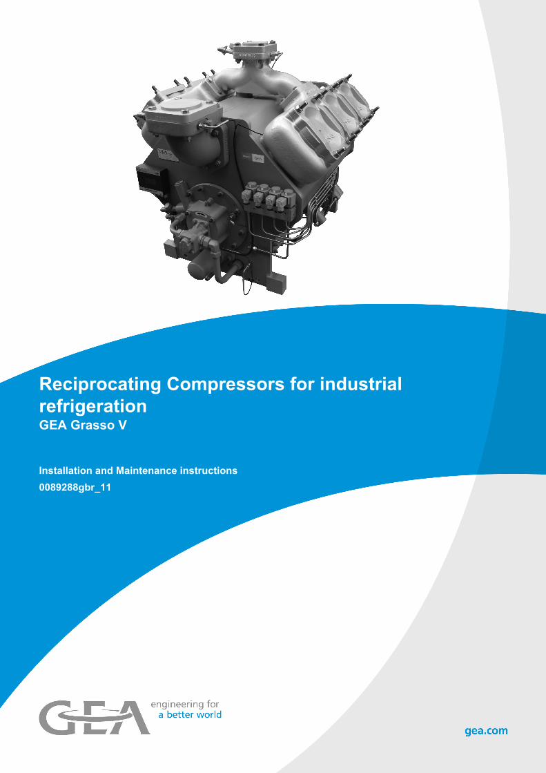
Reciprocating Compressors for industrialrefrigerationGEA Grasso V
Installation and Maintenance instructions0089288gbr_11
COPYRIGHT
All Rights reserved. No part of this publication may be copied or published bymeans of printing, photocopying, microfilm or otherwise without prior writtenconsent of GEA.This restriction also applies to the corresponding drawings and diagrams.
LEGAL NOTICE
This publication has been written in good faith. However, GEA cannot be heldresponsible, neither for any errors occurring in this publication nor for theirconsequences.
0089288gbr_112 30.10.2017

SYMBOLS USED
Danger
Stands for an immediate danger leading to severe physical injuries or death.► Description for avoiding the danger.
Warning!
Stands for a potentially dangerous situation leading to severe physicalinjuries or death.► Description for avoiding the dangerous situation.
Caution!
Stands for a potentially dangerous situation which could lead to minorphysical injuries or damage to property.► Description for avoiding the dangerous situation.
Notice!
Stands for important information that must be observed for the intended useand function of the product.► Description of the required action for the intended function of the product.
SAFETY INSTRUCTIONS
Hint!
This manual must be carefull read and understood prior to installingand servicing the compressor (package)
Safety
This manual is written with great care, but the contractor/installer is heldresponsible to examine this information and to take care of possible additionaland/ or deviated safety measures.
Safety instructions
It is the task of the contractor/installer to inform and explain to his client theoperation of the compressor (Package).Do respect all federal, state or local safety regulations/legislations duringinstalling, connecting and operating this compressor (package).
Construction changes
Warning!
In compliance with the regulations of the Pressure EquipmentDirective it is mandatory that no changes be made to the constructionof pressurised parts such as the crankcase housing, suction filterhousing etc.
0089288gbr_11 30.10.2017 3

Installer oriented information
The compressor (package) is filled with nitrogen to prevent penetration ofmoisture. Therefore, keep the compressor closed until the compressor (package)is being installed.
Warning! The compressor is not filled with oil.
Hint!
After the successful initial run of the compressor (package) thewarranty chart must be filled in and returned to Grasso. A warrantychart is attached to each compressor.
0089288gbr_114 30.10.2017
PREFACE
General
1. All documentation can be downloaded via our web site.
2. GEA technical manuals includes “generic paragraphs”; this means that it canoccur that not all data as described is relevant for the current compressorseries as mentioned in this manual. (For instance, not all compressor seriesare suitable for all mentioned refrigerants or not all compressor seriesincludes two-stage compressors)
Directives
Equipment is based on Pressure Equipment Directive (PED 97/23/EG)regulations and according to Machine Directive (MD 2006/42/EG) regulations.
The applied standards are:NEN-EN-IEC 60204, NEN-EN-ISO 12100, NEN-EN-ISO 13857, NEN-EN 378
0089288gbr_11 30.10.2017 5

0089288gbr_116 30.10.2017

CYLINDER NUMBERING, BOOSTER AND SINGLE-STAGE OPERATION
Cylinder numbering
Fig.1: Example cylinder numbering 6 cylinder compressor
Booster or single-stage operation
1. Booster operation applies if condensing temperature < +5 oC
2. Single-stage operation applies if condensing temperature >= +5 oC
0089288gbr_11 30.10.2017 7

0089288gbr_118 30.10.2017

GENERAL INFO
Main setup data
DescriptionValue
RemarkGrasso V 300 (T) .. V 600 (T) Grasso V 700 (T) .. V 1800 (T)
Start frequency max. 6 starts per hour
The NO-solenoid has to bede-energised 20 seconds
after starting the compressormotor to enabel the motor to
reach the minimum speed andthe compressor to develop the
required oil pressure.
Time interval between stoppingand re-starting min. 2 minutes
Time interval between startingand re-starting min. 10 minutes
Time interval between loadingand unloading min. 3 minutes
For continuous minimum part-load (i.e. more than 30
minutes) consult Grasso.Adjust the steps between upand down loading, in such a
way that the system is runningstable.
Oil level 25-75% crankcase sight glass
Min. oil temperature > 30 oC and > Psaturated crankcase pressure + 15 K
Indicated minimum value is thelowest oil temp. at which thecompressor is allowed to be
started.
Max. oil temperature Refer to oil selection table/applied type of oil
Required oil viscosity;≥ 10 cSt during operation at
location of bearings.The maximum temp. dependson the operating conditions ofthe compressor, the oil type
used and (A minimum actual oilviscosity of 10 cSt in the
bearings is always requried;bearing temp. to determine oil
viscosity is approx. oiltemperature + 15K)
Control oil pressure suction pressure + 8 bar (g)
Lubricating oil pressuredifference between 1.3 and 4.5 bar Setting approx. 2.0 bar (g)
After a mimimum of 15 minutesrunning time at an oil
temperature of approx. 50 oC
Max. discharge temperature 170 °C Min. suction pressure 0.3 bar(a)
Max. intermediate pressureMax. suction pressure
8.5 bar (a) 7 bar (a)
Pdischarge - Psuction ≤ 25.0 bar (g) ≤ 19.0 bar (g)
Superheat >0 K Oil discharge - running in -
filterFactory mounted; to be replaced after max. 100 running hours by “normal” oil discharge filterelement
Oil discharge filter Supplied loose; replacement for factory mounted running in filter
0089288gbr_11 30.10.2017 9

0089288gbr_1110 30.10.2017
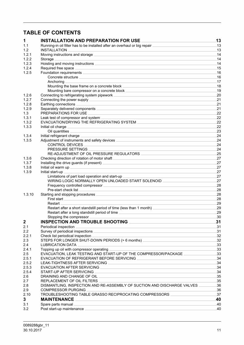
TABLE OF CONTENTS1 INSTALLATION AND PREPARATION FOR USE 131.1 Running-in oil filter has to be installed after an overhaul or big repair 131.2 INSTALLATION 131.2.1 Moving instructions and storage 141.2.2 Storage 141.2.3 Hoisting and moving instructions 141.2.4 Required free space 151.2.5 Foundation requirements 16
Concrete structure 16Anchoring 17Mounting the base frame on a concrete block 18Mounting bare compressor on a concrete block 19
1.2.6 Connecting to refrigerating system pipework 201.2.7 Connecting the power supply 211.2.8 Earthing connections 211.2.9 Separately delivered components 211.3 PREPARATIONS FOR USE 221.3.1 Leak test of compressor and system 221.3.2 EVACUATION/DRYING THE REFRIGERATING SYSTEM 221.3.3 Initial oil charge 22
Oil quantities 231.3.4 Initial refrigerant charge 241.3.5 Adjustment of instruments and safety devices 24
CONTROL DEVICES 24PRESSURE SETTINGS 24RE-ADJUSTMENT OF OIL PRESSURE REGULATORS 25
1.3.6 Checking direction of rotation of motor shaft 271.3.7 Installing the drive guards (if present) 271.3.8 Initial oil warm up 271.3.9 Initial start-up 27
Limitations of part load operation and start-up 27WIRING LOGIC NORMALLY OPEN UNLOADED START SOLENOID 27Frequency controlled compressor 28Pre-start check list 28
1.3.10 Starting and stopping procedures 28First start 28Restart 29Restart after a short standstill period of time (less than 1 month) 29Restart after a long standstill period of time 29Stopping the compressor 30
2 INSPECTION AND TROUBLE SHOOTING 312.1 Periodical inspection 312.2 Survey of periodical inspections 312.2.1 Check list periodical inspection 322.3 STEPS FOR LONGER SHUT-DOWN PERIODS (> 6 months) 322.4 LUBRICATION DATA 332.4.1 Topping up oil with compressor operating 332.5 EVACUATION, LEAK TESTING AND START-UP OF THE COMPRESSOR/PACKAGE 332.5.1 EVACUATION OF REFRIGERANT BEFORE SERVICING 342.5.2 LEAK-TIGHTNESS AFTER SERVICING 342.5.3 EVACUATION AFTER SERVICING 342.5.4 START-UP AFTER SERVICING 342.6 DRAINING AND CHANGE OF OIL 352.7 REPLACEMENT OF OIL FILTERS 352.8 DISMANTLING, INSPECTION AND RE-ASSEMBLY OF SUCTION AND DISCHARGE VALVES 362.9 COMPRESSOR PURGING 362.10 TROUBLESHOOTING TABLE GRASSO RECIPROCATING COMPRESSORS 373 MAINTENANCE 403.1 Spare parts manual 403.2 Post start-up maintenance 40
0089288gbr_11 30.10.2017 11

3.3 First maintenance 403.4 SMS FACTOR 413.5 Legend 413.6 Description Maintenance ABC when GMM is applied 423.6.1 Compressor 433.6.2 Package components 443.7 Grasso V 300 .. 1800 (T), WITHOUT GMM 464 APPENDIX; Product Information (PI) 504.1 GRASSO MAINTENANCE MONITOR 504.2 GENERAL LIMITS OF OPERATION GRASSO V 514.3 STARTING UP OF TWO-STAGE COMPRESSORS 524.4 DIAGRAMS SINGLE STAGE AND BOOSTER 544.5 DIAGRAMS TWO STAGE 554.6 LUBRICATING OILS (choice and recommendations) 584.6.1 STRONGLY RECOMMENDED OIL TYPES 584.6.2 ACCEPTED NH3 OIL TYPES 594.7 Pre-lubrication oil system 60
0089288gbr_1112 30.10.2017

1 INSTALLATION AND PREPARATION FOR USE
1.1 Running-in oil filter has to be installed after an overhaul or big repair
Hint!
This is why and when the running in oil filters are required:
Warning!
A running in oil filter has always to be installed after an overhaul orbig repair for the 1st 100 hours of operation!The oil and oil oil filters have to be replaced by new oil and filters.Due to running-in wear of liners and piston rings, it's normal that theoil becomes grey during the 1st 100 operating hours.After 100 operating hours, the oil could slightly become clear again.
1.2 INSTALLATION
Warning!
The compressor is not charged with oil, therefore, DO NOT start thecompressor before it has been installed and prepared according toGrasso’s instructions.
This section contains instructions for the proper installation of a Grassocompressor (package). Before the compressor (package) is ready for the initialstart up, the installation instructions in the following paragraphs must be followed:
1. The Compressor (Package) should be levelled and securely anchored to thefoundation.
2. All piping should be completed.
3. The system and the compressor are to be pressure tested for leaks (see.Section 1.3.1, Page 22)
4. The system should be evacuated to remove air and moisture.
5. The electric wiring should be completed as per wiring diagrams. Do notenergise the main power control cabinet until oil is added and the direction ofrotation has been checked.
6. The compressor is to be filled with the correct type and amount of lubricatingoil and has to be pre-lubricated (Refer Section 4.7, Page 60) before the firststart.
7. ‘Open compressors’ only;
7.1 Open compressors;The drive system should be installed.
7.2 (Semi) hermitic compressors;Mark R-S-T-N power supply in the terminal box of the motor.
INSTALLATION AND PREPARATION FOR USERunning-in oil filter has to be installed after an overhaul or big repair
0089288gbr_11 30.10.2017 13
8. The system should be charged with the correct amount of refrigerant.
9. The oil should be warmed up above minimum start up oil temperature (see"Product Information").
10. The control cabinet should be energised to check the package controls.
Hint!
Do not forget to charge the oil separator (if present) initially with oil, tothe level of the float assembly
1.2.1 Moving instructions and storage
For loose component or compressor package weights, refer either to the relevantcomponent type plate or package lay-out or to the suppliers document. For barecompressor weights, see "Product Information".
Caution!
Every precaution must be taken while moving the package to its finallocation. Pushing, pulling or climbing on any package component orpiping, can easily create damage.
1.2.2 Storage
The compressor (package) is filled with dry nitrogen. Keep the system closeduntil the package is installed. If the compressor (package) is stored, it should bekept at all times in a dry location to prevent corrosion damage. If the compressor(package) is to be stored for a prolonged period of time, it should be checkedweekly to ensure that the holding charge of dry nitrogen remains aboveatmospheric pressure.
1.2.3 Hoisting and moving instructions
Fig.2: Hoisting a compressor package
INSTALLATION AND PREPARATION FOR USEINSTALLATION
0089288gbr_1114 30.10.2017

Packaged base frame:
The only places that can be used for safe hoisting of the package are the fourhoisting eyes on the steel base frame as shown in the above figure. Prior tohoisting a compressor package with a V-belt drive arrangement, the factorymounted drive guard has to be removed. Attach spreader bars to the slings so asto prevent damage to piping and components.
Warning!
DO NOT use the compressor or motor or oil separator hoisting eyes tomove the package! These hoisting eyes are intended for lifting loosecomponents only and not for the entire package!
Bare compressor or loose components:
Determine the dead weight of the particular component (see "Product Information(ED)"), prior to moving a bare compressor or loose component. Use the hoistingeyes only, DO NOT sling from other compressor parts (see Figure 3, Page 15).
Fig.3: Hoisting angle
Moving by fork-lift truck
The bare compressor or package can be transported with a fork-lift truck with theforks spread as much as possible between the skids. To simplify moving, the 2wooden transport beams must still be mounted underneath the base frame andstored in this way, until the package is positioned above its approximate location.
1.2.4 Required free space
For easy operating, servicing and maintenance access, the compressor(package) should be installed with sufficient free space around it.
Hint!
Refer to “Product Information“ for minimum requirements.
INSTALLATION AND PREPARATION FOR USEINSTALLATION
0089288gbr_11 30.10.2017 15

1.2.5 Foundation requirements
Hint!
Compressor (package) has to be mounted on a concreted block. Onrequest, Grasso can calculate the exact dimensions of the concreteblock, based on the compressor size and operating conditions.
This paragraph covers measures to be taken for a compressor (package)mounting on a concrete block.Two foundation arrangements are described:
1. Compressor package with steel base frame mounted on a concrete block.Following base frames are possible;
1.a Frame designed for mounting on concrete block.For more instalation details refer to; Section 1.2.5.1, Page 16,Section 1.2.5.2, Page 17, Section 1.2.5.3, Page 18, Section ,Page 19, Section , Page 19.
1.b Frame designed for mounting on vibration dampers.For more details in case mounting base frames on vibration dampers isapplied, refer to separate instruction sheet and other orderdocumentation like package drawing, supplied with the compressorpackage and consult Grasso if required.
2. Bare compressor direct mounted on a concrete block via grouted anchors.For more installation details refer to; Section 1.2.5.1, Page 16,Section 1.2.5.2, Page 17, Section 1.2.5.4, Page 19.
1.2.5.1 Concrete structure
Fig.4: Concrete block
1 Cork board
2 Concrete base
3 (Concrete) Floor
4 Sand
The concrete block for compressor and motor or compressor package shouldhave a profile as illustrated in Page 16 and made according to the followingrecommendations:
INSTALLATION AND PREPARATION FOR USEINSTALLATION
0089288gbr_1116 30.10.2017

• The concrete block should be set on firm footings or on a floor capable ofcarrying the weight of the concrete block and capable of absorbing the freeforces and gas forces of the compressor during operation. The ground underthe concrete block should be horizontal and flat.
• The top surface of the block should be level and even.
• There should be sufficient free space around the block to install corkboard (orsimilar).
• The block should be provided with anchor bolt recesses or holes according tothe anchor bolt spacing as per package lay out drawing.
Fig.5
A Chemical anchor
B Grouted anchor, grounded to reinforcing steel
It is recommended to consult a concrete specialist/ constructor for the followingitems:
• The compound of the concrete with/without reinforcement.
• The exact grouting depth (dependent on the soil conditions).
• Installing foundation onto an existing floor, with sealing corkboard or vibrationisolators.
1.2.5.2 Anchoring
After the concrete block has cured the anchors should be installed as shownabove and in case of a package in accordance with the package lay out drawing.Templates should be made to locate the anchor bolts or chemical anchors tomatch the holes in the bottom flange of the base frame.
Grout the mortar according to the supplier instructions. Install chemical anchorsas illustrated in Figure 6, Page 18 and according to the instructions of theanchor supplier.
INSTALLATION AND PREPARATION FOR USEINSTALLATION
0089288gbr_11 30.10.2017 17
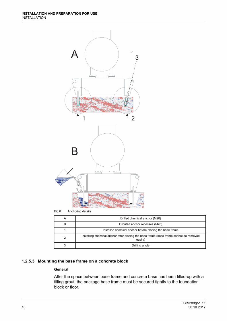
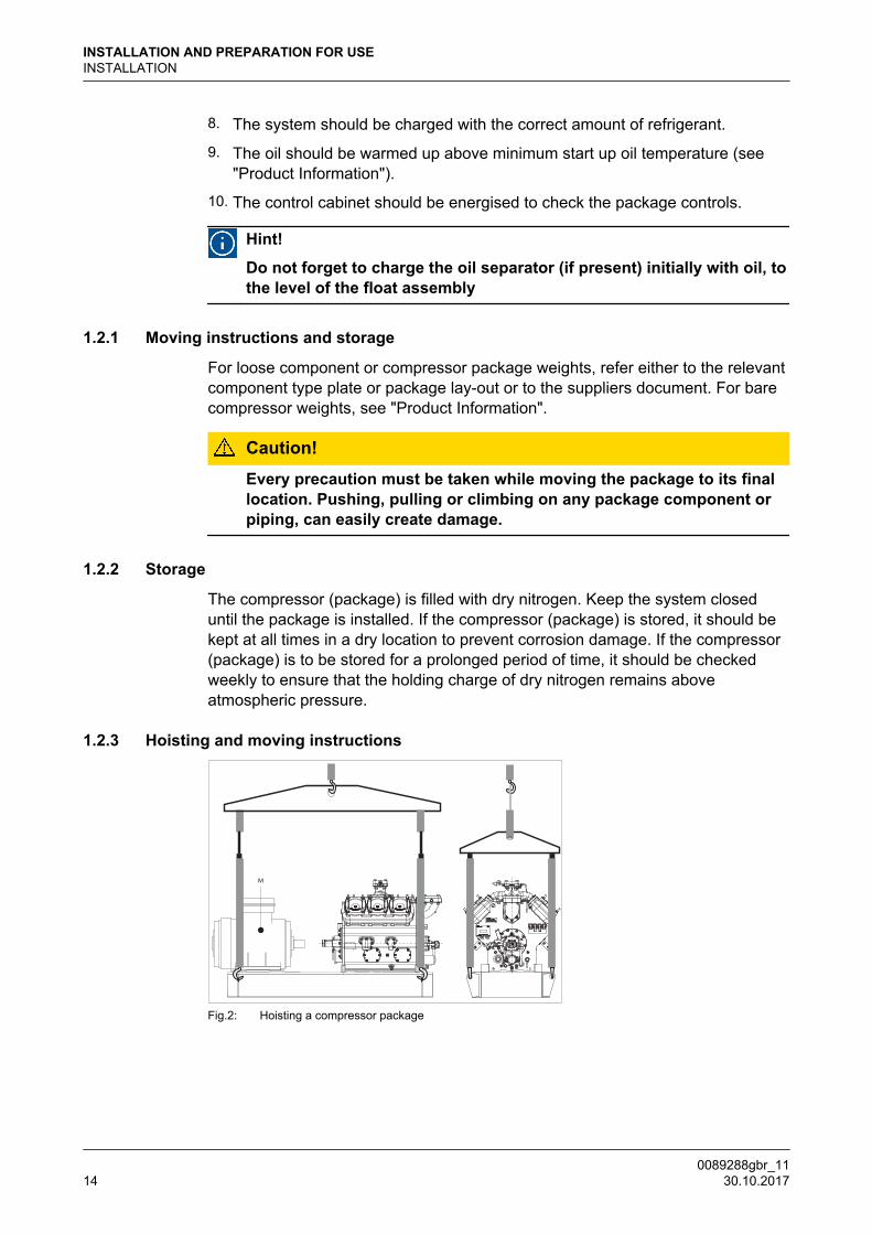
Fig.6: Anchoring details
A Drilled chemical anchor (M20)
B Grouted anchor recesses (M20)
1 Installed chemical anchor before placing the base frame
2 Installing chemical anchor after placing the base frame (base frame cannot be removedeasily)
3 Drilling angle
1.2.5.3 Mounting the base frame on a concrete block
General
After the space between base frame and concrete base has been filled-up with afilling grout, the package base frame must be secured tightly to the foundationblock or floor.
INSTALLATION AND PREPARATION FOR USEINSTALLATION
0089288gbr_1118 30.10.2017
Levelling the base frame
Fig.7: Grouting details
1 Self-levelling grout
2 Adjusting bolts (4x)
3 Washer
4 Temporary barrier strip around and inside frame
5 Complete cured concrete block
6 Grout layer
After the anchor filling mortar has completely cured the frame should be levelledwith a space between block and lower frame flange of 3 - 5 mm*. This space isnecessary for levelling using the base frame adjusting bolts with metal washers(supplied separately). The base frame should be levelled on each frame side.Adjust the frame on each adjusting place until all frame sides are horizontal.
This space largely depends on the sort of grout or mortar used. Determine thisspace according to the instructions of the grout or mortar supplier.
Finishing with a self-levelling grout
After levelling has been completed the adjusting bolt ends must be greased toavoid bonding to the self-levelling grout. The space between concrete block andframe must be completely filled with the self-levelling grout to ensure that thecomplete bottom surface of the base frame will be supported. Therefore, it is notallowed to use shims between concrete base and base frame.
Grouting must be carried out in accordance with the instructions provided by thegrouting supplier. After complete de-aeration of the grouted layer, secure thebase frame by tightening the anchor bolt nuts and remove all adjusting bolts. Atthis stage the drive system can be installed. These (accessories) installationinstructions can be found in the order manual.
1.2.5.4 Mounting bare compressor on a concrete block
INSTALLATION AND PREPARATION FOR USEINSTALLATION
0089288gbr_11 30.10.2017 19

If base frame is not applied the approximately the same procedure of levelling thebase frame has to be applied for the bare shaft compressor (referSection 1.2.5.3, Page 18).The mounting surfaces of the compressor feet must be level without anydeviation and projecting at least 10 mm above the concrete base.
Fig.8: Grouting details of bare compressor on concrete block
Legend
1 Self leveling grout
2 Foundation anchor
3 Layer of self leveling grout (10 - 15 mm)
4 Temporary barrier strip aroud each compressor foot
5 Complete cured concrete block
CF Compressor foot
WLWidth of grout layer(WL-WC > 40 mm)
WCWidth of compressor foot
(WL-WC > 40 mm)
1.2.6 Connecting to refrigerating system pipework
Warning! DO NOT ground through the compressor when arc welding
After the compressor (package) has been levelled and secured to the foundation,the system piping may be connected. The suction line(s) and discharge line(s)should be installed and supported such that there is no load exerted on thecompressor. The size and location of the suction and discharge connections, canbe found in the "Product Information" (bare compressor) and in case of apackage, the package lay out drawing.
Hint!
If an oil rectifier system is applied in the refrigeration system, the oilreturn line must be connected to the oil return connection (see"Product Information").
INSTALLATION AND PREPARATION FOR USEINSTALLATION
0089288gbr_1120 30.10.2017

Suspension of system pipework
To eliminate vibration transmission to the system piping, the following isrecommended:
• Install all piping free of tension.
• Secure the piping by clips or brackets in two directions.
• Install (stop) valves, piping and accessories such, that there is no loadexerted on the compressor.
1.2.7 Connecting the power supply
Information about further electrical connections to be made (e.g. crankcaseheater, drive motor starting equipment, thermal protection of drive motor,automatic start/ stop and other external electrical devices) can be found in theplant manual (not supplied by Grasso).
1.2.8 Earthing connections
Grasso compressors and packages are equipped with litz-wires and earthconnecting points.To avoid leakage current flowing through the components, disconnect all litz-wires when arc-welding. After all installation functions are completed, reconnectthe litz-wires and ground the package to earth.
1.2.9 Separately delivered components
Hint!
Check whether the sets/parts/components belonging to thiscompressor are supplied loose! (Refer to order confirmation)
Mount these separately delivered sets, components and/or parts, according tothe instructions as supplied with this compressor (package).
INSTALLATION AND PREPARATION FOR USEINSTALLATION
0089288gbr_11 30.10.2017 21

1.3 PREPARATIONS FOR USE
After the Compressor (Package) has been installed (excluding final connection ofdrive device), the following actions should be followed in the order given:
1.3.1 Leak test of compressor and system
The compressor (package) has been pressure tested prior to leaving the factory.In case an additional leak test is required, this test is should be carried out withdry nitrogen.
Hint!
DO NOT add oil to the compressor prior to pressure testing
A system leak test should be carried out over 24 hours to ensure that the systemis tightly sealed.Record during the pressure test, the pressure, ambient temperature and outsidetemperature. During the initial 6 hours a pressure drop of 2% is permissable. Withrespect to temperature variations, no further pressure loss should be detected inthe remaining 18 hours.
1.3.2 EVACUATION/DRYING THE REFRIGERATING SYSTEM
For evacuation of compressor only, refer to Section 2.5, Page 33
Procedure to evacuate and to dry a system:
i. STATUS: System is filled with nitrogen and no oil has been added (oilprevents any trapped moisture from boiling off).
ii. Verify that all valves in that part of the system to be evacuated are opened(refer also to the plant manual).
iii. Connect vacuum pump to the evacuation/purging valve(s) of the compressor(for location of these valves refer to the "Product Information" or to aconnection as mentioned in the plant manual and evacuate the system toapprox. 6 mBar.
iv. Break vacuum by charging dry nitrogen into the system.
v. Repeat step iii, "Connect vacuum pump ...".
vi. Wait approx. 24 hours.
vii. If pressure has increased (system still contains moisture), repeat steps iv, andvi. Otherwise, continue with the "Initial oil charge" procedure.
1.3.3 Initial oil charge
INSTALLATION AND PREPARATION FOR USEPREPARATIONS FOR USE
0089288gbr_1122 30.10.2017

Warning!
Oil charging via the suction line of the compressor is not allowed.Used or filtered oil should NEVER BE added to a compressor underany circumstance.Use only new oil as selected from the Grasso oil table. (ReferChapter 4, Page 50)
Procedure:
i. STATUS: System is dried and still evacuated.
ii. Charge the oil separator (if present) initially with oil .
iii. Close suction and discharge stop valves of compressor and oil return line ofoil separator (if present).
iv. Charge the compressor crankcase with oil via the oil charge valve.
Warning! Pre-lubrication just before the first start is obligatory.
Hint!
Filling of the afore mentioned components is also possible by meansof a separate oil filling pump via the oil charge valves mounted ontothe oil pump housing.
1.3.3.1 Oil quantities
Number of cylindersShaft seal housing incl.
internal circuit ofcrankshaft O
il fil
ter O
il pump
Crankcase(max/min)
V 300(T)
0.7 1.5 0.9
17.0 / 12.5
V 450 23.9 / 17.6
V 600(T) 34.6 / 25.5
V 700(T) 22.4 / 16.5
V 1100(T) 31.9 / 23.5
V 1400(T) 45.6/ 33.6
V 1800(T) 55.1/40.6
INSTALLATION AND PREPARATION FOR USEPREPARATIONS FOR USE
0089288gbr_11 30.10.2017 23
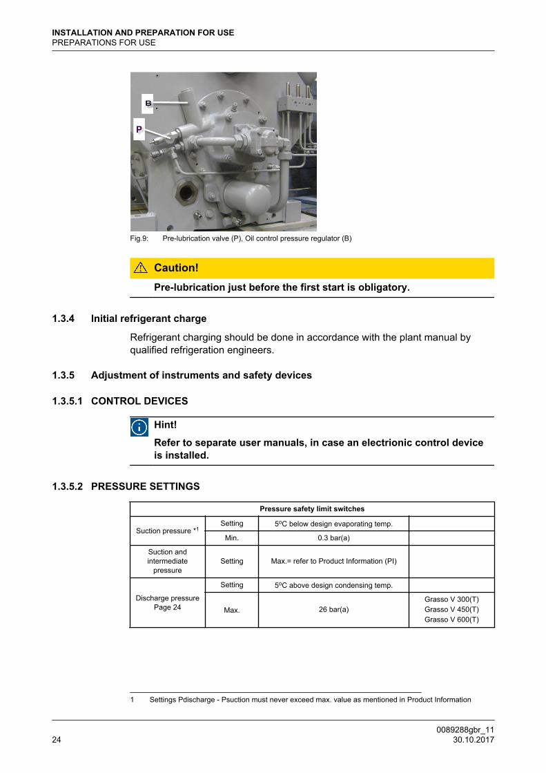
Fig.9: Pre-lubrication valve (P), Oil control pressure regulator (B)
Caution! Pre-lubrication just before the first start is obligatory.
1.3.4 Initial refrigerant charge
Refrigerant charging should be done in accordance with the plant manual byqualified refrigeration engineers.
1.3.5 Adjustment of instruments and safety devices
1.3.5.1 CONTROL DEVICES
Hint!
Refer to separate user manuals, in case an electrionic control deviceis installed.
1.3.5.2 PRESSURE SETTINGS
Pressure safety limit switches
Suction pressure *1Setting 5oC below design evaporating temp.
Min. 0.3 bar(a)
Suction andintermediate
pressureSetting Max.= refer to Product Information (PI)
Discharge pressurePage 24
Setting 5oC above design condensing temp.
Max. 26 bar(a)Grasso V 300(T)Grasso V 450(T)Grasso V 600(T)
1 Settings Pdischarge - Psuction must never exceed max. value as mentioned in Product Information
INSTALLATION AND PREPARATION FOR USEPREPARATIONS FOR USE
0089288gbr_1124 30.10.2017

Pressure safety limit switches
24 bar(a)
Grasso V 700(T)Grasso V 1100(T)Grasso V 1400(T)Grasso V 1800(T)
Lubrication oilpressure difference Setting Min. =1.3 bar
Oil pressure regulators
Lubrication oil pressuredifference *2
Setting 2.0 bar
Min. and max.at 50 oC oil temp.
Min.=1.3 barMax.=4.5 bar
Control oil pressure difference Setting 8.0 bar
1.3.5.3 RE-ADJUSTMENT OF OIL PRESSURE REGULATORS
It is possible that after the compressor has been installed, the lubrication oilpressure regulator needs to be adjusted.
Location pressure regulators (control and lubricaton)
Fig.10: Oil lubrication pressure regulator (A)
2 The oil pressure regulator is adjusted at the works, but it may occur that this setting should be correctedduring the initial run and also if the value <1.5 or >2.5 bar. The re-adjustment procedure is given in section“Re-adjustment of oil pressure regulator.
INSTALLATION AND PREPARATION FOR USEPREPARATIONS FOR USE
0089288gbr_11 30.10.2017 25
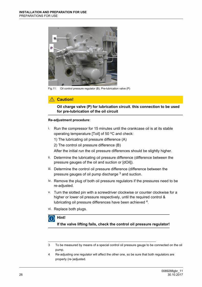
Fig.11: Oil control pressure regulator (B), Pre-lubrication valve (P)
Caution!
Oil charge valve (P) for lubrication circuit. this connection to be usedfor pre-lubrication of the oil circuit
Re-adjustment procedure:
i. Run the compressor for 15 minutes until the crankcase oil is at its stableoperating temperature [Toil] of 50 oC and check:1) The lubricating oil pressure difference (A)2) The control oil pressure difference (B)After the initial run the oil pressure differences should be slightly higher.
ii. Determine the lubricating oil pressure difference (difference between thepressure gauges of the oil and suction or [dOil]).
iii. Determine the control oil pressure difference (difference between thepressure gauges of oil pump discharge 3 and suction.
iv. Remove the plug of both oil pressure regulators if the pressures need to bere-adjusted.
v. Turn the slotted pin with a screwdriver clockwise or counter clockwise for ahigher or lower oil pressure respectively, until the required control &lubricating oil pressure differences have been achieved 4.
vi. Replace both plugs.
Hint!
If the valve lifting fails, check the control oil pressure regulator!
3 To be measured by means of a special control oil pressure gauge to be connected on the oilpump.
4 Re-adjusting one regulator will affect the other one, so be sure that both regulators areproperly (re-)adjusted.
INSTALLATION AND PREPARATION FOR USEPREPARATIONS FOR USE
0089288gbr_1126 30.10.2017

1.3.6 Checking direction of rotation of motor shaft
Prior to installing the intermediate coupling element or V-belts, the direction ofrotation of the motor shaft must be checked. The direction of rotation can bedetermined from the arrow-sticker at the oil pump.
1.3.7 Installing the drive guards (if present)
Only after the compressor is ready for the initial startup! Refer to the drive guardinstalling procedures included in the order documentation.
1.3.8 Initial oil warm up
Prior to the initial start-up, the crankcase heater (if present) must be energised.For the min. oil temperature refer to “Product Information (PI)“.
1.3.9 Initial start-up
1.3.9.1 Limitations of part load operation and start-up
The capacity control serves to adapt the compressor capacity at any moment asclosely as possible to the refrigerating capacity. In order to adjust the capacity, anumber of cylinders can be put in or out of action either individually or collectivelyby means of solenoid valves.
Warning!
Due to start-up limitations and to limitations of part load operation itmay be that not all available part load steps are allowed under certainconditions. Use of incorrect control steps can damage compressorand/or components.
For a detailed description about start-up and part load limitations refer to GEAGrasso Selection Software.
1.3.9.2 WIRING LOGIC NORMALLY OPEN UNLOADED START SOLENOID1. If compessor is NOT running then NO-solenoid is not energised.
2. Energise the NO-solenoid 10 - 20 seconds before starting.
3. If compressor starts then NO-solenoid is energised and de-energised bymeans of an auxiliary time relay.
4. Ensure that the NO-solenoid valve is not de-energised until the minimumallowed compressor speed has been achieved and the specified lubrication oilpressure has been established.
5. Energise the NO-solenoid 5 seconds before stopping until the compressor isstopped completely.
INSTALLATION AND PREPARATION FOR USEPREPARATIONS FOR USE
0089288gbr_11 30.10.2017 27

1.3.9.3 Frequency controlled compressor
Hint!
In case of frequency controlled compressors, a separate instruction00.87.041 is required. If you don’t have this instruction consult Grasso.
1.3.9.4 Pre-start check list
The following Paragraph covers only the initial start of the compressor and notthe complete refrigeration plant.
Be sure that all necessary system valves are open and that the refrigerationsystem is ready for start up. Use the following check to guarantee that no items ofimportance regarding the compressor (package) have been overlooked.
i. System is charged with refrigerant.
ii. Settings of safety limit switches are adjusted properly.
iii. Direction of rotation of compressor crankshaft is correct.
iv. Check capacity control: Set the electrical capacity control to the position of thelowest part load step.
v. Oil level established in sight glass.
vi. Stop valves to the pressure gauges are open.
vii. Suction stop valve is closed (in case the evaporating temperature is muchhigher than the design evaporating temperature) and the discharge stop valveis open and in case of two- stage compressors that the stop valves in theintermediate circuit lines are open.
viii.
Stop valve in the oil return line of the oil separator (if present) is closed.
When all items are verified, the compressor (package) is ready for the start-up.
1.3.10 Starting and stopping procedures
Hint!
For all limitations refer to "Main setup data"-overview! The values inthe main setup data tables, overrules the values as mentioned in thetext.
When starting the compressor a distinction should be made between:
1.3.10.1 First start
1. Notice "Pre-start check list", also consult the plant manual and verify thefollowing items:
– Check the oil temperature (refer to the "Product Information").
– Check crankcase oil level (refer to Section 2.4.1, Page 33).
INSTALLATION AND PREPARATION FOR USEPREPARATIONS FOR USE
0089288gbr_1128 30.10.2017

2. Start the compressor and check whether the oil pressure increases.
Warning!
The time interval between stopping and starting should be at least 2minutes and between starting and re-starting 10 minutes.
3. Slowly open suction stop valve and watch suction pressure, which may notexceed the max. value.
Warning!
Refrigerant liquid hammer, will damage the compressor; Dry gas(superheat) is always necessary!
4. In case of electrically operated capacity control:One or more cylinders will be energized.
5. Watch maximum allowable motor current (refer to motor type plate).
6. Watch discharge temperature and max. allowable motor current (refer tomotor type plate).
7. Adjust pressure gauge stop valves, in order to avoid vibration of the pointers.(if present)
8. Open the stop valve in the oil return line from the oil separator (if present).
9. After 50 hours of operation retighten the coupling bolts or check and/orcorrect the tension of the V-belts and retighten the foundation bolts (with duerespect to the torque settings given by the supplier of the fasteners!).
1.3.10.2 Restart
Hint!
For the time interval between stopping and starting refer to "Mainsetup data"-overview.
Proceed to the complete starting procedure like “First start“
1.3.10.3 Restart after a short standstill period of time (less than 1 month)
• Refer to Section 1.3.10.2, Page 29.
1.3.10.4 Restart after a long standstill period of time
After a seasonal standstill (1 till 6 months) or maintenance operations;
Warning!
After a standstill period of time more than 1 month, pre-lubrication justbefore starting is always obligatory. Refer Section 4.7, Page 60
• Check settings of control and safety equipment.
• Proceed to the complete starting procedure.
INSTALLATION AND PREPARATION FOR USEPREPARATIONS FOR USE
0089288gbr_11 30.10.2017 29
Warning!
Restarting compressor after a standstill period of time more than 6months, consult your supplier. It is recommended to proceed with theinitial start up procedure.
1.3.10.5 Stopping the compressor
The compressor can be stopped at any moment, however, consult the supplier iffurther actions are required.
INSTALLATION AND PREPARATION FOR USE
0089288gbr_1130 30.10.2017

2 INSPECTION AND TROUBLE SHOOTING
2.1 Periodical inspection
These inspections should be made during the normal shut-down periods as muchas possible, so the compressor is always ready to operate when required. If, atthat time, the number of running hours slightly differs from the scheduled periodbelow, the inspection should nevertheless be carried out.
In this way it will not be necessary to stop the compressor at inconvenient times.The frequency of inspections is dependent on the type of installation, operatingconditions and local regulations. In the case of automatically controlled plants,the periodical inspection are particularly important. The table below sums up allthe points on the compressor that have to be inspected or maintained along withinspection and maintenance frequencies.
2.2 Survey of periodical inspections
Apart from the check points in the table below, the sound produced by thecompressor also provides an indication of its mechanical condition. If abnormalsounds are audible, their cause should be traced and removed immediately inorder to prevent serious breakdowns.
INSPECTION AND TROUBLE SHOOTINGPeriodical inspection
0089288gbr_11 30.10.2017 31
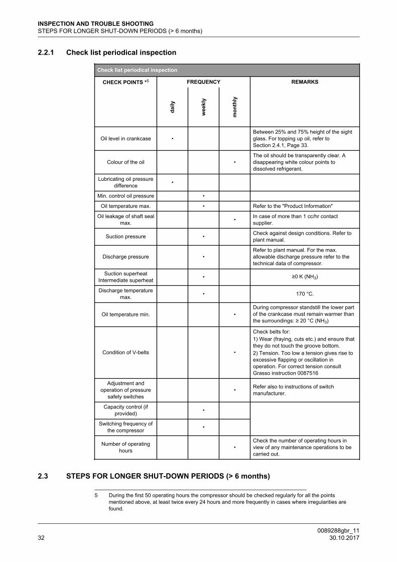
2.2.1 Check list periodical inspection
Check list periodical inspection
CHECK POINTS *5 FREQUENCY REMARKS
daily
wee
kly
mon
thly
Oil level in crankcase • Between 25% and 75% height of the sightglass. For topping up oil, refer toSection 2.4.1, Page 33.
Colour of the oil •The oil should be transparently clear. Adisappearing white colour points todissolved refrigerant.
Lubricating oil pressuredifference •
Min. control oil pressure • Oil temperature max. • Refer to the "Product Information"
Oil leakage of shaft sealmax. • In case of more than 1 cc/hr contact
supplier.
Suction pressure • Check against design conditions. Refer toplant manual.
Discharge pressure • Refer to plant manual. For the max.allowable discharge pressure refer to thetechnical data of compressor.
Suction superheatIntermediate superheat • ≥0 K (NH3)
Discharge temperaturemax. • 170 °C.
Oil temperature min. •During compressor standstill the lower partof the crankcase must remain warmer thanthe surroundings: ≥ 20 °C (NH3)
Condition of V-belts •
Check belts for:1) Wear (fraying, cuts etc.) and ensure thatthey do not touch the groove bottom.2) Tension. Too low a tension gives rise toexcessive flapping or oscillation inoperation. For correct tension consultGrasso instruction 0087516
Adjustment andoperation of pressure
safety switches • Refer also to instructions of switch
manufacturer.
Capacity control (ifprovided) •
Switching frequency of
the compressor •
Number of operatinghours •
Check the number of operating hours inview of any maintenance operations to becarried out.
2.3 STEPS FOR LONGER SHUT-DOWN PERIODS (> 6 months)
5 During the first 50 operating hours the compressor should be checked regularly for all the pointsmentioned above, at least twice every 24 hours and more frequently in cases where irregularities arefound.
INSPECTION AND TROUBLE SHOOTINGSTEPS FOR LONGER SHUT-DOWN PERIODS (> 6 months)
0089288gbr_1132 30.10.2017
To shut down a compressor for long term periods, proceed as follows:
i. Tightly shut both the suction and discharge stop valves and the stop valve ofthe oil return line (if present).
ii. Disconnect the power source from the compressor drive motor and theelectrical control cabinet.
iii. Place a moisture absorbing compound (eg a dessicant such as silica gel)inside the control cabinet.
iv. Place warning tags on the electric system and all closed stop valves.
Prior to starting up after a shut down, change the oil and exchange the oil filters.Determine the starting and stopping procedure from prior to start the compressor.
2.4 LUBRICATION DATA
Determine max Toil and set this value in the safety device.Change the oil as soon as an oil analysis indicates contaminated oil.
Warning!
It is expressly pointed out that it is not permitted to mix different typesof oil. If another type of oil is used, first remove all the stale oil in thefilters, oil pump, crankcase, shaft seal, oil separator and oil drains ofthe installation.
2.4.1 Topping up oil with compressor operating
Hint!
Use Grasso’s hand-operated oil pump, part. no. 18.13.121
Topping up oil is permitted during compressor operation.
Be sure that this oil is the same as in the plant (refer to Section 2.4, Page 33).
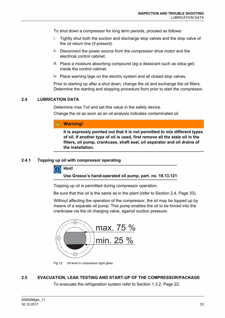
Without affecting the operation of the compressor, the oil may be topped up bymeans of a separate oil pump. This pump enables the oil to be forced into thecrankcase via the oil charging valve, against suction pressure.
Fig.12: Oil level in compressor sight glass
2.5 EVACUATION, LEAK TESTING AND START-UP OF THE COMPRESSOR/PACKAGETo evacuate the refrigeration system refer to Section 1.3.2, Page 22,
INSPECTION AND TROUBLE SHOOTINGLUBRICATION DATA
0089288gbr_11 30.10.2017 33

Always use a vacuum pump or pump-down unit to evacuate the refrigerant fromthe compressor.
2.5.1 EVACUATION OF REFRIGERANT BEFORE SERVICING
Procedure to evacuate the compressor:
1. Switch off main control panel
2. Remove main fuses
3. Close shut-off valves
4. Remove the refrigerant by means of a vacuum pump or pump-down unit, viathe evacuation/purging valve(s) as prescribed by local safety regulations. Forthe location of these valves refer to the "Product Information".
5. Drain the oil from the compressor and oil separator, oil return /oil rectifiersystem if present.
2.5.2 LEAK-TIGHTNESS AFTER SERVICINGThe necessary safety precautions should be taken before carrying out the leak-tightness test. To check leak-tightness use dry nitrogen at a positive pressurewhich is less than the admissible operating pressure of the low pressure stage.
2.5.3 EVACUATION AFTER SERVICINGAfter the pressure test has been completed, the compressor (package) must beevacuated and undergo a vacuum test. Evacuation is used to remove air andmoisture from the compressor (package)
2.5.4 START-UP AFTER SERVICING1. STATUS: Compressor (package) is dried and still evacuated.
2. Charge the oil separator, if present, with oil.See the appropriate Product Information for the correct quantity.
3. Charge the compressor crankcase with oil via the oil charge valve until theminimum level is seen at the sight glass at the level as indicated in IMM.It is mandatory to pre-lubricate the oil circuit by adding the final quantity of oilvia the charge valve mounted onto the oil pump by means of a separate oilfilling pump. The required oil level is indicated in the IMM.
4. Re-install all accessories such as coupling, V-belt guard etc.
5. Open the shut-off valves.
6. Check the start-stop procedure.
7. Check all safeties and controls.
8. Re-install the main fuses.
9. Start up the compressor.
10. Check running condition.
Note:
INSPECTION AND TROUBLE SHOOTINGEVACUATION, LEAK TESTING AND START-UP OF THE COMPRESSOR/PACKAGE
0089288gbr_1134 30.10.2017

The job isn't finished until the paper work is done! Complete the service report,e.g. Grasso report 00.89.062.
2.6 DRAINING AND CHANGE OF OIL
To top up oil see Section 2.4.1, Page 33, Oil changing procedure:
i. Evacuate the compressor (refer to Section 2.5, Page 33).
ii. Drain the oil via the oil charging/drain valve. Remove the cover of one or moreservice openings on the compressor side.
iii. Clean the inside of the crankcase with a non-fibrous cloth (do not use cottonwaste!).
iv. Replace the service cover(s) with a new seal.
v. Charge crankcase with clean oil in accordance with the procedure.
2.7 REPLACEMENT OF OIL FILTERS
General
The frequency of exchanging oil discharge filter, oil suction filter and compressorsuction gas filter(s) depends on the condition of the refrigeration system. Besidesthe maintenance schedules, it is recommended to exchange all filters when thecompressor is overhauled and also in case the refrigeration plant has beenmodified.
Hint!
An oil discharge oil running-in filter is factory mounted. This oil filtermust be exchanged after max. 100 running hours. This oil filter cannotbe cleaned.
Fig.13: Oil control pressure regulator (1), oil discharge filter(2), oil pump (3)
Oil discharge filter
Hint!
Use the special tool for (dis)mounting the oil discharge filter element
Evacuate the compressor prior to exchange any filters.
INSPECTION AND TROUBLE SHOOTINGDRAINING AND CHANGE OF OIL
0089288gbr_11 30.10.2017 35

2.8 DISMANTLING, INSPECTION AND RE-ASSEMBLY OF SUCTION AND DISCHARGEVALVES
Hint!
A high working temperature and rapid temperature variations shortenthe life time of the valves, which, for this reason, require regularinspection.
The suction and discharge valves of a refrigeration compressor are parts that areheavily loaded both mechanically and thermally. Wear and life time of the valvesstrongly depend on the working conditions of the compressor. It is recommendedthat valve condition is regularly checked.For dismantling, inspection and re-assembly of the valves, refer to the relevant paragraph of the CompressorService Instruction Manual.
Hint!
In order to reduce the downtime involved in the valve inspection, it isrecommended to have as many complete valve assemblies in stock asthere are cylinders on the compressor.These valves can be exchangedwith the original valves; in this case, these original valves can beinspected and repaired or replaced if necessary later.
2.9 COMPRESSOR PURGING
Procedure to purge the compressor (after maintenance jobs):
STATUS:
Stop valves of suction, discharge and oil return line are still closed (refer toSection 2.5, Page 33) and compressor is filled with oil (refer to Section 2.6,Page 35).
i. Connect a vacuum pump to the evacuation/purging valve(s) and evacuate asprescribed by local regulations. For the location of these valves refer to the"Product Information".
ii. When evacuation is completed open the discharge stop valve.
iii. Watch suction and discharge pressure.
Hint!
If suction pressure increases quickly, the discharge valve assy isleaking.
iv. Start compressor.
v. Slowly open suction stop valve.
vi. Open the stop valve in the oil return line of the oil separator (if present).
vii. For two stage compressor only;
vii.a Two-stage system A/B: open liquid supply to interstage cooler.
vii.b Two-stage system C/D: refer to the plant manual.
INSPECTION AND TROUBLE SHOOTINGDISMANTLING, INSPECTION AND RE-ASSEMBLY OF SUCTION AND DISCHARGE VALVES
0089288gbr_1136 30.10.2017
viii.
If a Self-Limiting Automatic Purger is not installed, purge the refrigeratingsystem (refer to the plant manual).
2.10 TROUBLESHOOTING TABLE GRASSO RECIPROCATING COMPRESSORS
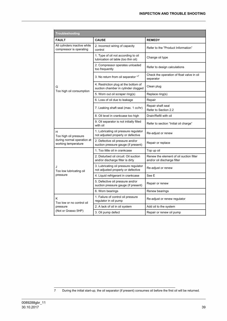
The troubleshooting table shown overleaf may be helpful to quickly trace andremedy failures that interfere with the proper operation of the compressor. It isemphatically pointed out that the cause of a failure must often be sought in therefrigeration installation itself. Therefore, it is necessary besides this table also toconsult the plant manual.
INSPECTION AND TROUBLE SHOOTINGTROUBLESHOOTING TABLE GRASSO RECIPROCATING COMPRESSORS
0089288gbr_11 30.10.2017 37

Troubleshooting
FAULT CAUSE REMEDY
ADischarge pressure toohigh
1. Discharge stop valve not fullyopen Open fully
2. Discharge pressure gaugedefective Repair or replace
3. Non-condensables in the system Purge with a Automatic Purger
BDischarge temperature toohigh
1. Discharge pressure too high See A
2. Too many cylinders cut out Cut in more cylinders
3. Suction pressure too low See D
4. Excessive superheat of suctiongas Eliminate excessive superheat
5. For two-stage compressors:interstage cooling does not operateproperly
Repair
6. Room temperature too high Ventilate engine room better
7. Discharge valve defective Repair or renew
8. Pressure relief valve is leaking Repair or renew
CSuction pressure too high
1. Capacity control does notoperate Repair
2. Compressor capacity too small Refer to plant design
3. Suction pressure gauge defective Repair or renew
4. One or more suction valvesdefective Renew suction valve rings
5. One or more discharge valvesdefective Repair or renew
6. Pressure relief valve is leaking Repair or renew
DSuction pressure too low
1. Suction stop valve not fully open Open fully
2. Suction gas strainer blocked Renew
3. Injection control not adjustedcorrectly Re-adjust control
4. Too little refrigerant in installation Top-up with refrigerant
5. Suction pressure gauge defective Renew
ECrankcase frosted or wet*6
Warning!
Stop compressor and contact installation engineer
1. Liquid refrigerant in crankcasedue to:
1a. Room temperature too low Provide for crankcase heating or, ifprovided, check it for proper operation
1b. Oil return from separatorcontains liquid refrigerant Consult plant manual
1c. Installation operates too wet Re-adjust installation and provide forsuperheat
1d. Liquid separator too small Consult plant manual
F1. Oil pressure for valve liftingmechanism too low See J
6 In case of R744 applications only, crankcase can be frosted or wet, during normal operating conditions.
INSPECTION AND TROUBLE SHOOTINGTROUBLESHOOTING TABLE GRASSO RECIPROCATING COMPRESSORS
0089288gbr_1138 30.10.2017
Troubleshooting
FAULT CAUSE REMEDY
All cylinders inactive whilecompressor is operating
2. Incorrect wiring of capacitycontrol Refer to the "Product Information”
GToo high oil consumption
1. Type of oil not according to oillubrication oil table (too thin oil) Change oil type
2. Compressor operates unloadedtoo frequently Refer to design calculations
3. No return from oil separator *7 Check the operation of float valve in oilseparator
4. Restriction plug at the bottom ofsuction chamber in cylinder clogged Clean plug
5. Worn out oil scraper ring(s) Replace ring(s)
6. Loss of oil due to leakage Repair
7. Leaking shaft seal (max. 1 cc/hr)Repair shaft sealRefer to Section 2.2
8. Oil level in crankcase too high Drain/Refill with oil
9. Oil separator is not initially filledwith oil Refer to section “Initial oil charge”
HToo high oil pressureduring normal operation atworking temperature
1. Lubricating oil pressure regulatornot adjusted properly or defective Re-adjust or renew
2. Defective oil pressure and/orsuction pressure gauge (if present) Repair or replace
JToo low lubricating oilpressure
1. Too little oil in crankcase Top up oil
2. Disturbed oil circuit: Oil suctionand/or discharge filter is dirty
Renew the element of oil suction filterand/or oil discharge filter
3. Lubricating oil pressure regulatornot adjusted properly or defective Re-adjust or renew
4. Liquid refrigerant in crankcase See E
5. Defective oil pressure and/orsuction pressure gauge (if present) Repair or renew
6. Worn bearings Renew bearings
KToo low or no control oilpressure(Not or Grasso 5HP)
1. Failure of control oil pressureregulator in oil pump Re-adjust or renew regulator
2. A lack of oil in oil system Add oil to the system
3. Oil pump defect Repair or renew oil pump
7 During the initial start-up, the oil separator (if present) consumes oil before the first oil will be returned.
INSPECTION AND TROUBLE SHOOTING
0089288gbr_11 30.10.2017 39

3 MAINTENANCE
3.1 Spare parts manual
Hint!
A complete spare parts overview is available as a separate manual.Download the parts list manual via internet (DocNav) or consultGrasso.
3.2 Post start-up maintenance
After the compressor has run for the initial 100 operating hours:
i. Drain the oil and refill the compressor with the correct amount of fresh oil.
ii. Replace the running oil discharge filter element with the “permanent“ filterelement in accordance with the filter replacement instructions.
iii. Inspect suction gas filter (refer to the Compressor Service InstructionManual).
iv. Exchange or clean oil suction filter element.
v. Check the compressor shaft seal for leakage. If excessive (more than 1 cc/hr)replace the seal.
vi. 1) Retighten the coupling mounting bolts with the torque settings as given bythe coupling manufacturer.2) Verify and if necessary, correct the tension of the V-belts as given in theGrasso instruction 0087516.
vii. Verify and if necessary, correct the torque settings of all foundation bolts asgiven in Compressor Service Instruction Manual.
3.3 First maintenance
Hint!
For complete conditional service schedules and service intervals,refer to Guideline for Conditional maintenance.After the refrigerating plant has been modified, the suction gasfilter(s), the oil filters and the oil must be changed.
Maintenance Number of operating hours
100 8 > 100
Renewal of oil discharge filter X
refer to Guideline for ConditionalMaintenance
Inspection of suction gas filter(s) X
Inspection of oil suction filter(strainer) X
8 Time dependent on pollution.
MAINTENANCESpare parts manual
0089288gbr_1140 30.10.2017

Maintenance Number of operating hours
100 8 > 100
Oil analysis 9 X
Inspection leakage shaft seal X
3.4 SMS FACTOR
General
The following maintenance has to be distinguished:
1. Grasso Maintenance Monitor (GMM) is appliedMaintenance A, B and C, service intervals are determined on measuredvalues of GMM
2. GMM is not applied:Service intervals according to Service and Maintenance Schedules (SMS)tables in combination with operating conditions
Warning!
GMM is not used: The running hours mentioned in the SMS tablesshould only be used as a reference for maintenance intervals.The number of running hours mentioned in the SMS tables have to beadjusted accordingly depending on the operating conditions of thecompressor (speed, evaporating temperature, condensingtemperature, refrigerant, start frequency, capacity control steps, etc..This means that the service intervals could be significantly different.The running hours mentioned in the tables are based on a single stagecompressor running at -10oC/+35oC, NH3 at nominal speed. In thiscase the SMS factor = 1, in all other cases the maintenance intervalshave to be adjusted accordingly.
3.5 Legend
Warning!
These operations cover routine maintenance and are meant as a guideonly. Lack of maintenance, frequency of stop/starting, extremeoperating conditions etc could lead to accelerated wear.
General;
The service and maintenance schedules use the codes as explained in the tablebelow;
8 Time dependent on pollution.9 Consult your oil supplier.
MAINTENANCESMS FACTOR
0089288gbr_11 30.10.2017 41

Actions
Legend for service and maintenance schedules (SMS)
Item Code/Actions Description
1 IC Inspection / Alternatively renewal - correcting / Testing
2 IV Inspection Visual / Alternatively electrical testing
3 RE Renewal
4 ME Measure
5 CL Clean
3.6 Description Maintenance ABC when GMM is appliedThe information in this section has to be used when GMM is applied.
Hint!
This section is only valid in case the Grasso Maintenance Monitor(GMM) is applied.
General
The following maintenance has to be distinguished;
1. Small maintenance, Maintenance A, Yearly inspection
2. Medium maintenance, Maintenance B
3. Large maintenance, Maintenance C
Description maintenance A;
1. Replace/clean oil discharge filter, clean oil suction filter
2. Visual inspection of cylinders and crankcase
3. Visual inspection of cylinder no. 1
4. Check compressor running conditions
5. Check/test safety equipment
Description maintenance B;
1. Maintenance A +
2. Replace suction and discharge valve rings and springs (“top end“ overhaul)
3. Inspection of pistons and cylinder liners
Description maintenance C;
1. Maintenance B +
2. Major inspection/overhaul;Depending on requirements and expectations, required actions have to betaken. (complete disassembly, replacement of bearings, inspection/replacement of all main components like crankshaft, cylinder liners,pistons, ...)
MAINTENANCEDescription Maintenance ABC when GMM is applied
0089288gbr_1142 30.10.2017

3.6.1 Compressor
General remarks about check list;
1. Check list for compressor only; all other components have to be maintainedaccording to their specific manuals (IMM and SIM).
2. All items of the list below marked “check“, have to be checked visually andchecked for proper working.
3. Some components have to be measured.For measuring details refer to SIM.
4. Measuring means also that visual inspection is required.
5. Visual inspections:The visual inspections during maintenance are of importance; measurementsshould be carried out at the moment that visually abnormalities are detected.The result of the inspection determines whether one or more parts have to bereplaced. For more detailed information refer (SIM) and Installation andMaintenance Manual (IMM).
6. Oil and oil return systems:The quality of the oil effects the oil consumption and the life time of themoving parts. For oil return systems or systems in which soluble oil is beingused, we advise to check (or have checked) the quality of the oil every 5000hours and - if necessary - to renew the oil and/or filters. If there is no oilanalysis available, we advise to renew the oil. By regularly carrying out oilanalyses and registering them in a log, aberrations will be noticed in an earlystage, which may prevent or reduce resultant damage(s).
Note 1:When renewing the oil, in the crankcase the oil in the oil separator and the oilreturn or oil rectifier system (if fitted) has to be renewed.
Note 2:Pre-lubricate the compressor before re-starting. Used or filtered oil shouldNEVER be added to a compressor under any circumstance. Use only new oilas selected from the Grasso oil table. Oil charging via the suction line of thecompressor is not allowed.
Grasso Maintenance Monitor (GMM) is applied
Maintenance compressorDescription
A B C
Check Check CheckCapacity control
Solenoid valve and coils
Check Replace Seals of cap control piston / lifting mechanism
Check Check Check Compressorhousing Oil return orifice (LP and) HP
Check Check Check Crankcase heater
Measure Crankshaft Main (and intermediate) bearings, runningsurface
Visualinspection Connecting rod
Cylinder located nearest to the shaft-end of thecompressor:
MAINTENANCEDescription Maintenance ABC when GMM is applied
0089288gbr_11 30.10.2017 43

Grasso Maintenance Monitor (GMM) is applied
Maintenance compressorDescription
A B C
Visualinspection Measure Big and small end bearing, running surface
Clean Clean Clean Compressorhousing Inside and outside
Visualinspection Measure
Cylinder linersCylinder located nearest to the shaft-end of the
compressor
Measure All cylinder liners
Check Check Check Drive Coupling alignment
Check Check Check Interstage cooler Inspections and injection valves
Clean Clean Clean
Filters
Oil suction filter
Replace. Replace Replace Oil discharge filter
Check Clean Clean Suction gas
Check Check Check
Oil
Oil analysis recommended
Ifhygroscop
ic oil isapplied:Replace
Replace Replace Oil refreshment compresssor, oil separator andoil system
Visualinspection
Visualinspection
Oil pump element, oil control and lubricationpressure regulator
Check Check Check Lubrication and control system
Check Clean Clean Oil separator, test oil return system
Clean Clean Clean Oil cooler fan / heat exchanger
Visualinspection Replace
PistonRings
Visualinspection Measure Gudgeon pin
Visual
inspection+ TEST
Visualinspection+ TEST
Relief valve(s)
Check Check Check Shaft seal Oil & Refrigerant leak range
Visualinspection Compressor valves
Cylinder located nearest to the shaft-end of thecompressor:
Suction and discharge valves, springs, damperrings
Check Replace Replace Suction and discharge compressor valves
Check Thrust bearing Running surface
3.6.2 Package components
Checklist package components
Description/checkpoint
1 Drive guard
2 V-belts and alignment
3 Coupling alignment
4 Oil level float switch on compressor and oil separator
MAINTENANCEDescription Maintenance ABC when GMM is applied
0089288gbr_1144 30.10.2017

Checklist package components
Description/checkpoint
5 Pressure safety switches
6 Pressure gauges
7 Thermostats and thermometers
8 Electrical control system
9 Oil return protection and oil return system
10Electric motor and thermistors(Consult motor manufacturer)
11 Base frame, vibration dampers and bolts
12 Piping
13 Interstage cooler, interstage injection
15 Oil cooler (oil side and air side) and fan
16 Thermo-Master
MAINTENANCEDescription Maintenance ABC when GMM is applied
0089288gbr_11 30.10.2017 45
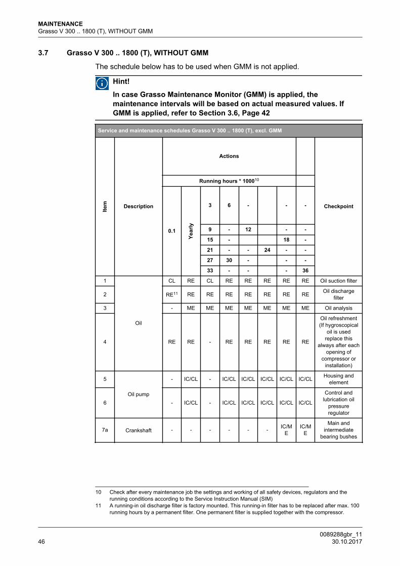
3.7 Grasso V 300 .. 1800 (T), WITHOUT GMM
The schedule below has to be used when GMM is not applied.
Hint!
In case Grasso Maintenance Monitor (GMM) is applied, themaintenance intervals will be based on actual measured values. IfGMM is applied, refer to Section 3.6, Page 42
Service and maintenance schedules Grasso V 300 .. 1800 (T), excl. GMM
Item Description
Actions
Checkpoint
Running hours * 100010
0.1
Year
ly
3 6 - - -
9 - 12 - -
15 - 18 -
21 - - 24 - -
27 30 - - -
33 - - - 36
1
Oil
CL RE CL RE RE RE RE RE Oil suction filter
2 RE11 RE RE RE RE RE RE RE Oil dischargefilter
3 - ME ME ME ME ME ME ME Oil analysis
4 RE RE - RE RE RE RE RE
Oil refreshment(If hygroscopical
oil is usedreplace this
always after eachopening of
compressor orinstallation)
5
Oil pump
- IC/CL - IC/CL IC/CL IC/CL IC/CL IC/CL Housing andelement
6 - IC/CL - IC/CL IC/CL IC/CL IC/CL IC/CL
Control andlubrication oil
pressureregulator
7a Crankshaft - - - - - - IC/ME
IC/ME
Main andintermediate
bearing bushes
10 Check after every maintenance job the settings and working of all safety devices, regulators and therunning conditions according to the Service Instruction Manual (SIM)
11 A running-in oil discharge filter is factory mounted. This running-in filter has to be replaced after max. 100running hours by a permanent filter. One permanent filter is supplied together with the compressor.
MAINTENANCEGrasso V 300 .. 1800 (T), WITHOUT GMM
0089288gbr_1146 30.10.2017

Service and maintenance schedules Grasso V 300 .. 1800 (T), excl. GMM
Item Description
Actions
Checkpoint
Running hours * 100010
0.1
Year
ly
3 6 - - -
9 - 12 - -
15 - 18 -
21 - - 24 - -
27 30 - - -
33 - - - 36
7b - - - - - - IC/ME
IC/ME
Running surfacesmain and
intermediatebearings
crankshaft
8 - IC/ME - IC/M
EIC/M
EIC/M
EIC/M
EIC/M
ERunning surfaces
con. rods
9 Shaft seal - IC IC IC IC IC IC IC Oil/refrigerantleakage
10 Conrod - IC/ME - IC/M
EIC/M
EIC/M
EIC/M
EIC/M
EBig and smallend bearings
11
Pistons
- IC - IC IC IC IC IC Piston
12 - IC - IC IC IC IC IC Piston rings
13 - IC/ME - IC/M
EIC/M
EIC/M
EIC/M
EIC/M
E Gudgeon pin
14 Thrust bearing - IV/ME - IV/M
EIV/M
EIV/M
EIV/M
EIV/M
E
Runningsurfaces/Axial
play
15
Capacity control
IC/IV IC/IV IC/IV IC/IV IC/IV IC/IV IC/IV IC/IV Solenoid valvesand coils
16 - RE - RE IV IV RE RE Seals of cap.control piston
17 - IC - IC IC IC IC IC Cap. Controlmechanism
18
Compressorhousing
IC/IV IC/IV IC/IV IC/IV IC/IV IC/IV IC/IV IC/IV Crankcaseheater
19 CL CL - CL CL CL CL CL Crankcase
20 - - - - IC IC IC ICNon returnvalves LP/
Restrictions HP
21 - IV - IV IV IV IV IV Relief valves
10 Check after every maintenance job the settings and working of all safety devices, regulators and therunning conditions according to the Service Instruction Manual (SIM)
MAINTENANCEGrasso V 300 .. 1800 (T), WITHOUT GMM
0089288gbr_11 30.10.2017 47

Service and maintenance schedules Grasso V 300 .. 1800 (T), excl. GMM
Item Description
Actions
Checkpoint
Running hours * 100010
0.1
Year
ly
3 6 - - -
9 - 12 - -
15 - 18 -
21 - - 24 - -
27 30 - - -
33 - - - 36
22 RE12 IC/CL IC/CL IC/CL IC/CL IC/CL IC/CL IC/CL Suction gas filter
23
Discharge valves
- IC - IC RE RE IC RE Valves, springsand damper rings
24 - IC/CL - IC/CL IC/CL IC/CL IC/CL IC/CLStroke limitor/
Discharge valveseat
25 Suction valves - IC - IC RE RE IC RE Valves, springsand damper rings
26Cylinder liners
- IV - IV IV IV IV IV Cap. Controllifting mechanism
27 - IV/ME - IV/M
EIV/M
EIV/M
EIV/M
EIV/M
EDimension andrunning profile
28Drive
IC IC IC IC IC IC IC IC Alignment
29 IC IC IC IC IC IC IC IC V-belts
30 Electric motor Refer to specifications of motor manufacturer
31
Optionals
IC IC IC IC IC IC CL/IC CL/IC Oil level switch
32 IC IC IC IC IC IC IC IC Safety switches
33 IC IC IC IC IC IC IC IC Gauges
34 IC IC IC IC IC IC IC IC Thermostats
35 IC IC IC IC IC IC IC IC Thermometers
36 IC IC IC IC IC IC IC IC Electrical controlsystem
37 IC IC IC IC IC IC CL/IC CL/IC Valve oil returnprotection
38 IV IV IV IV IV IV IV IV Thermistors
39 IC IC IC IC IC IC IC ICVibration
dampers andbolts
10 Check after every maintenance job the settings and working of all safety devices, regulators and therunning conditions according to the Service Instruction Manual (SIM)
MAINTENANCEGrasso V 300 .. 1800 (T), WITHOUT GMM
0089288gbr_1148 30.10.2017

Service and maintenance schedules Grasso V 300 .. 1800 (T), excl. GMM
Item Description
Actions
Checkpoint
Running hours * 100010
0.1
Year
ly
3 6 - - -
9 - 12 - -
15 - 18 -
21 - - 24 - -
27 30 - - -
33 - - - 36
40 IC/ME
IC/ME
IC/ME
IC/ME
IC/ME
IC/ME
IC/ME
IC/ME
Intermediatecooler and
injection valve
41 CL CL - CL CL CL CL CL
Oil separatorrefreshing oil andcleaning/testing
of float valve
42 - IC IC IC IC RE IC IC Heavy duty thrustbearing
43 CL CL CL CL CL CL CL CL Oil cooler, airside
44 RE RE - RE RE RE RE REOil cooler, oil
side, refrigerationoil
45 Refer to specifications of motor manufacturer Oil cooler, electicmotor (fan)
46 ME ME/CL
ME/CL
ME/CL
ME/CL
ME/CL
ME/CL
ME/CL
Cylinder headwater cooling
system
10 Check after every maintenance job the settings and working of all safety devices, regulators and therunning conditions according to the Service Instruction Manual (SIM)
12 A running-in suction gas filter is factory mounted. This running-in filter has to be replaced after max. 100running hours by a permanent filter. One permanent filter is supplied together with the compressor
MAINTENANCE
0089288gbr_11 30.10.2017 49

4 APPENDIX; Product Information (PI)
4.1 GRASSO MAINTENANCE MONITOR
Hint!
In case the GSC-TP is included, the GMM hardware is not required,since the GSC-TP includes the GMM software.
Fig.14: Grasso Maintenance Monitor
GMM connections
1 Ethernet
2 Power input (10 .. 30 VDC)
3 Compressor speed sensor
4 Discharge temperature sensor
5 Oil temperature sensor
The Grasso micro processor controlled maintenance monitor is a uniquestandalone device for flexible maintenance. This equipment stronglyrecommended to fit on V series compressors to be able to tune the maintenanceto the actual running conditions. In other words: “On time maintenance”
This results in (nearly) all cases in longer service intervals and significantly lessmaintenance costs. For industrial refrigeration compressors this is a uniquedevelopment. To maintain the highest level of reliability, even with extendedservice intervals, this series is fitted with the best possible components available.
This standalone device works independent from compressor controls like theGrasso GSC OP/TP and must be seen as an addition on the normal compressorcontrol. In separate documents the complete maintenance philosophy and how tohandle is explained in detail.
APPENDIX; Product Information (PI)GRASSO MAINTENANCE MONITOR
0089288gbr_1150 30.10.2017

Besides this practical instrument Grasso is able to make, in advance, ananalyses based on a theoretical profile of the compressor and the runningconditions. In this way an indication of the running costs ( Total Costs ofOwnership, TCO) can be produced.
4.2 GENERAL LIMITS OF OPERATION GRASSO V
When operating the compressor, none of the limits of operation as stated in thetable below must be exceeded. *13
The diagrams overleaf represent the overall fields of application in which theindividual operation limits are taken into account.
General limits and fields of operation
REFRIGERANT NH3
Compressor speed n
Grasso V300(T) .. 600(T)
min.
500 min-1 for direct drive600 min-1 for V-belt drive
Grasso V700(T) ..1800(T)
500 min-1 for direct drive700 min-1 for V-belt drive
Grasso V300(T) .. 600(T)
max.
1500 min-1
Grasso V700(T) ..1800(T)
1200 min-1
Suction pressure = evaporatingpressure =crankcase pressure
po/to
Grasso V min.0.3 bar(a)
-55 °C
Grasso V300(T) .. 600(T)
max.
8.5 bar(a)19 °C
Grasso V700(T) ..1800(T)
7.0 bar(a)13 °C
Suction superheatdelta-t
Grasso Vmin. >0 °C
Superheat LP suction Grasso VT
Actual suction temperature ta Grasso V(T) min. -50 °C
Discharge pressure =condensing pressure
tc = saturated condensingtemperature *14
* 15Ps *16/
tc
Grasso V300(T) .. 600(T)
max.
26.0 bar(a)60 °C
Discharge pressure =condensing pressure *17
*18
Grasso V700(T) ..1800(T)
24.0 bar(a)56 °C
13 In practice, it is not so much the individual operation limits as combinations of them that aredecisive for the conditions under which a compressor may operate. To check the variouspossibilities in this respect, use should be made of the "fields of application" ).
14 This pressure is also the maximum allowable pre-set value of the HP safety switch.15 CAUTION!: When adjusting the HP and/or LP safety switch, care should be taken that the pressure
difference Δp=(pC-po) never exceeds 26.0 bar(g).16 “Ps“ is mentioned on type plate of the compressor17 This pressure is also the maximum allowable pre-set value of the HP safety switch.18 CAUTION!: When adjusting the HP and/or LP safety switch, care should be taken that the pressure
difference Δp=(pC-po) never exceeds 19.0 bar (g).
APPENDIX; Product Information (PI)GENERAL LIMITS OF OPERATION GRASSO V
0089288gbr_11 30.10.2017 51

General limits and fields of operation
REFRIGERANT NH3
Design pressure PSs *19 Grasso V(T) -
26.5 bar(a)This pressure deviates from the so
called max. dischargepressure=condensing pressure
(allowed during operation) as statedin the table.
Discharge temperaturete
Grasso Vmax.
+170 °CThis is the actual discharge
temperature, measured directly inthe gas flow just before the
discharge connection. The givenvalue also applies to the LP stage
of two-stage compressors.
Discharge temperature LP Grasso VT Pressure ratio per stage (pc/po
or pc/pm or pm/po)Pressure ratio limits are notabsolute but arbitrary values
based on practicalconsiderations
j -
min. 1.5
max. 10
Pressure difference delta-p
Grasso V300(T) .. 600(T) max.
(pc - po) <= 25.5 bar
The standard built-in overflowsafety valve(s)
(pc - pambient) <= 25.5 bar
Grasso V700(T) ..1800(T)
max.
(pc - po) <= 19.0 bar
The standard built-in overflowsafety valve(s)
(pc - pambient) <= 25.5 bar
Oil temperature in crankcase toil °C
min.
>10oC and > Tsaturated crankcase
pressure at stand still + 15 KIndicated minimum value is thelowest oil temperature at which thecompressor is allowed to be started.
max.
< 70 oC, depending on type of oilThe maximum oil temperaturedepends on the operatingconditions of the compressor andthe oil type used.A minimum actual oil viscosity of 10cSt in the bearings is alwaysrequired.
4.3 STARTING UP OF TWO-STAGE COMPRESSORS
Procedure for starting from compressor standstill
In the case of two-stage compressors it is very important that immediately afterthe period of automatic fully unloaded start (ensured by the corresponding three-way solenoid valve in the control pressure supply line from the oil pump; only oneor more H.P. cylinders become operative, viz. only those cylinders of which thesuction valve lifting mechanism is directly and permanently connected to the
19 “PSs“ is mentioned on type plate of the compressor (Possibly "Pd" is mentioned for compressorsdelivered before 1-Mar-2013)
APPENDIX; Product Information (PI)STARTING UP OF TWO-STAGE COMPRESSORS
0089288gbr_1152 30.10.2017

control pressure supply of the oil pump via the starting solenoid valve mentioned.This means that during starting none of the three-way solenoid valves for thecapacity control are allowed to be energized.
Procedure to move on to two-stage operation and to increase capacity.
Once properly started, as indicated in the previous paragraph, the compressorhas to be switched over to two-stage operation with minimum capacity, followed,if and when required, by gradual stepping up to maximum capacity.The procedure thereby to be applied depends on the installation operatingconditions during starting which give rise to two distinct possibilities, viz.:
1. The compressor is started at low evaporating temperatures, this beingapprox. the (design) value during normal (full-load) operation.This situation occurs after the compressor has been stopped for a certainperiod of time because of low capacity requirements of the installation. Underthese circumstances it is permitted to switch over to the two-stage part-loadstep of minimum capacity immediately after proper starting with H.P. cylindersin operation.In the case of NH3, this is even a necessity, for otherwise the compressorwould be running in single-stage under two-stage conditions, resulting in toohigh a discharge temperature.
2. The compressor is started at a relatively high evaporating temperature, that isto say much higher than under design conditions and in any case not suitablefor two-stage operation.Such a situation may occur after a prolonged period of compressor standstillor when the compressor operates on a batch type freezing tunnel, just loadedwith warm products. Under these circumstances it is not permitted to switchover to two-stage operation with minimum capacity until the H.P. cylindersalready in operation have lowered (in single-stage) the evaporatingtemperature so that the corresponding working point at the condensingtemperature tc, lies inside the field of application of the two-stage minimumpart-load step concerned. Only then, after this step has been energized, thesaturation intermediate temperature tm will be below its maximum value.Consequently, the maximum value of to at which it is allowed to switch over totwo-stage operation, is determined by the intersection of the near-vertical linewhich represents the right hand limitation of the relevant field of applicationand the horizontal line which represents the condensing temperature tc.
Likewise, during further stepping up to maximum capacity, the evaporatingtemperature has to be pulled down by each intermediate part-load step so farthat the corresponding working point at given condensing temperature lieseach time just inside the field of application of the next part-load step of highercapacity, before that step is energized.
Fast pull-down part-load control steps
When using the standard capacity control steps of the two-stage compressortypes, the pull-down procedure to achieve full-load operation at designconditions, as described in the previous paragraph, is rather often very timeconsuming. This is due to the fact that all compressor types are always started
APPENDIX; Product Information (PI)STARTING UP OF TWO-STAGE COMPRESSORS
0089288gbr_11 30.10.2017 53
with only one HP cylinder in operation and that the minimum LP/HP sweptvolume ratio for any part-load step is ϕ = 2.Therefore, for all Grasso two-stage types a fast pull- down electric capacitycontrol system has been developed, which allows the compressors to be startedwith two or more HP cylinders in operation and which includes one or more part-load steps with volume ratio ϕ = 1.
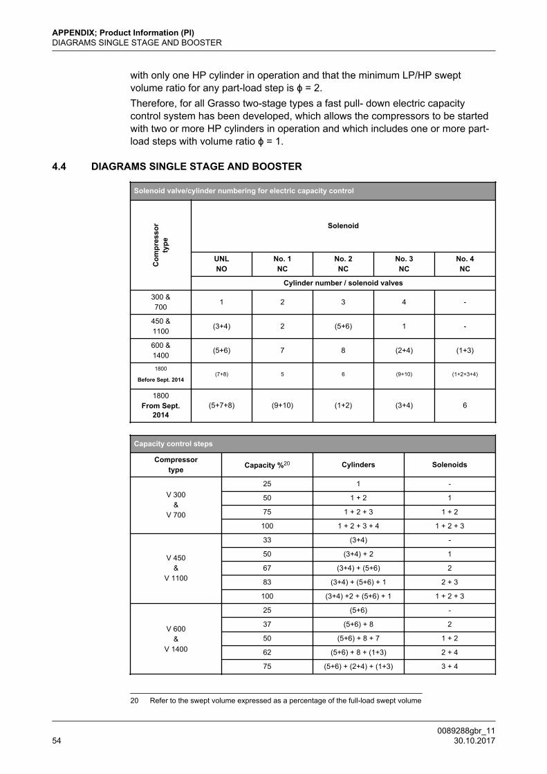
4.4 DIAGRAMS SINGLE STAGE AND BOOSTER
Solenoid valve/cylinder numbering for electric capacity control
Com
pres
sor
type
Solenoid
UNLNO
No. 1NC
No. 2NC
No. 3NC
No. 4NC
Cylinder number / solenoid valves
300 &700
1 2 3 4 -
450 &1100
(3+4) 2 (5+6) 1 -
600 &1400
(5+6) 7 8 (2+4) (1+3)
1800
Before Sept. 2014(7+8) 5 6 (9+10) (1+2+3+4)
1800From Sept.
2014(5+7+8) (9+10) (1+2) (3+4) 6
Capacity control steps
Compressortype Capacity %20 Cylinders Solenoids
V 300&
V 700
25 1 -
50 1 + 2 1
75 1 + 2 + 3 1 + 2
100 1 + 2 + 3 + 4 1 + 2 + 3
V 450&
V 1100
33 (3+4) -
50 (3+4) + 2 1
67 (3+4) + (5+6) 2
83 (3+4) + (5+6) + 1 2 + 3
100 (3+4) +2 + (5+6) + 1 1 + 2 + 3
V 600&
V 1400
25 (5+6) -
37 (5+6) + 8 2
50 (5+6) + 8 + 7 1 + 2
62 (5+6) + 8 + (1+3) 2 + 4
75 (5+6) + (2+4) + (1+3) 3 + 4
20 Refer to the swept volume expressed as a percentage of the full-load swept volume
APPENDIX; Product Information (PI)DIAGRAMS SINGLE STAGE AND BOOSTER
0089288gbr_1154 30.10.2017
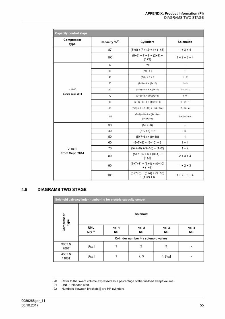
Capacity control steps
Compressortype Capacity %20 Cylinders Solenoids
87 (5+6) + 7 + (2+4) + (1+3) 1 + 3 + 4
100 (5+6) + 7 + 8 + (2+4) +(1+3) 1 + 2 + 3 + 4
V 1800
Before Sept. 2014
20 (7+8) -
30 (7+8) + 5 1
40 (7+8) + 5 + 6 1 + 2
50 (7+8) + 6 + (9+10) 2 + 3
60 (7+8) + 5 + 6 + (9+10) 1 + 2 + 3
70 (7+8) + 5 + (1+2+3+4) 1 +4
80 (7+8) + 5 + 6 + (1+2+3+4) 1 + 2 + 4
90 (7+8) + 6 + (9+10) + (1+2+3+4) 2 + 3 + 4
100(7+8) + 5 + 6 + (9+10) +
(1+2+3+4)1 + 2 + 3 + 4
V 1800From Sept. 2014
30 (5+7+8) -
40 (5+7+8) + 6 4
50 (5+7+8) + (9+10) 1
60 (5+7+8) + (9+10) + 6 1 + 4
70 (5+7+8) +(9+10) + (1+2) 1 + 2
80 (5+7+8) + 6 + (3+4) +(1+2) 2 + 3 + 4
90 (5+7+8) + (3+4) + (9+10)+ (1+2) 1 + 2 + 3
100 (5+7+8) + (3+4) + (9+10)+ (1+2) + 6 1 + 2 + 3 + 4
4.5 DIAGRAMS TWO STAGE
Solenoid valve/cylinder numbering for electric capacity control
Com
pres
sor
type
Solenoid
UNLNO 21
No. 1NC
No. 2NC
No. 3NC
No. 4NC
Cylinder number 22 / solenoid valves
300T &700T
[4hp ] 1 2 3 -
450T &1100T
[4hp ] 1 2, 3 5, [6hp] -
20 Refer to the swept volume expressed as a percentage of the full-load swept volume21 UNL, Unloaded start22 Numbers between brackets [] are HP cylinders
APPENDIX; Product Information (PI)DIAGRAMS TWO STAGE
0089288gbr_11 30.10.2017 55

Solenoid valve/cylinder numbering for electric capacity control
Com
pres
sor
type
Solenoid
UNLNO 21
No. 1NC
No. 2NC
No. 3NC
No. 4NC
Cylinder number 22 / solenoid valves
600T &1400T
[6hp ] 1, 2 3 4, [8hp] 5, 7
1800T [6hp ] 1, 2 7, [8hp], 9 5 3, 4, [10hp]
Capacity control steps
Compressortype Capacity %23 Cylinders Solenoids
Qty HP / Qty LPcylinders 24 Remark 25)
300T&
700T
0 [4] - 0.0 Starting only/ Fastpull down
33 1 + [4] 1 1.0 Starting only/Fastpull down
67 1 + 2 + [4] 1 + 2 2.0 -
100 1 + 2 + 3 + [4] 1 + 2 + 3 3.0 -
450T&
1100T
0 [4] - 0.0 Starting only/Fastpull down
25 1 + [4] 1 1.0 Starting only/Fastpull down
50 (2 + 3) + [4] 2 2.0 -
50 1 + [4] +(5 +[6]) 1 + 3 1.0 Starting only/Fast
pull down
75 1 + (2 + 3) +[4] 1 + 2 3.0 -
75 (2 + 3 )+ [4] +(5 + [6]) 2 + 3 1.5 Starting only/Fast
pull down
100 1+ 2 + 3 + [4]+ (5 + [6]) 1 + 2 + 3 2.0 -
600T&
1400T
0 [6] - 0.0 Starting only/Fastpull down
33 (1 + 2) + [6] 1 2.0 -
33 3 + [6] + (4 +[8]) 2 + 3 1.0 Starting only/Fast
pull down
50 (1 + 2) + 3 +[6] 1 + 2 3.0 -
50 (1 + 2) + [6] +(4 + [8]) 1 + 3 1.5 Starting only/Fast
pull down
67 (1 + 2) + [6] +(4 + [8]) 1 + 2 + 3 2.0 -
21 UNL, Unloaded start22 Numbers between brackets [] are HP cylinders23 Refer to the swept volume expressed as a percentage of the full-load swept volume of the LP cylinders24 Each phi has its own field of application! Refer Page 5625 For starting up procedure, refer Section 4.3, Page 52
APPENDIX; Product Information (PI)DIAGRAMS TWO STAGE
0089288gbr_1156 30.10.2017
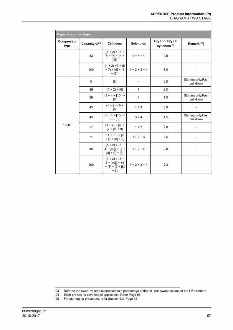
Capacity control steps
Compressortype Capacity %23 Cylinders Solenoids
Qty HP / Qty LPcylinders 24 Remark 25)
83(1 + 2) + (5 +7) + [6] + (4 +
[8])1 + 3 + 4 2.5 -
100(1 + 2) +3 + (5+ 7) + [6] + (4
+ [8])1 + 2 + 3 + 4 3.0 -
1800T
0 [6] - 0.0 Starting only/Fastpull down
29 (1 + 2) + [6] 1 2.0 -
29 (3 + 4 + [10]) +[6] 4 1.0 Starting only/Fast
pull down
43 (1 + 2) + 5 +[6] 1 + 3 3.0 -
43 (3 + 4 + [10]) +5 + [6] 3 + 4 1.5 Starting only/Fast
pull down
57 (1 + 2) + [6] +(7 + [8] + 9) 1 + 2 2.0 -
71 1 + 2 + 5 + [6]+ (7 + [8] + 9) 1 + 2 + 3 2.5 -
86(1 + 2) + (3 +
4 + [10]) + (7 +[8] + 9) + [6]
1 + 2 + 4 2.0 -
100
(1 + 2) + (3 +4 + [10]) + +5+ [6] + (7 + [8]
+ 9)
1 + 2 + 3 + 4 2.3 -
23 Refer to the swept volume expressed as a percentage of the full-load swept volume of the LP cylinders24 Each phi has its own field of application! Refer Page 5625 For starting up procedure, refer Section 4.3, Page 52
APPENDIX; Product Information (PI)DIAGRAMS TWO STAGE
0089288gbr_11 30.10.2017 57
4.6 LUBRICATING OILS (choice and recommendations)
Caution!
In case a Grasso compressor is used inside a GEA Grasso producedchiller, the applicable oils could be limited compared with the oilsmentioned in this chapter for use with NH3 as refrigerant. The oils tobe used will then be specified in the Chiller Product information.
Warning!
The choice of oil for a refrigeration compressor should be made bytaking into account the entire refrigeration system design andoperation as well as the operating conditions of the compressor.
For lubrication of refrigeration compressors, several brands and types of speciallydeveloped lubricating oils are on the market. The choice of oil depends not onlyon its good lubrication properties (viscosity) and chemical stability at theoperating conditions of the compressor, but also on the operating conditions ofthe refrigerating plant (solidifying and floc point, solubility).
Grasso has tested and approved for use in its reciprocating-compressors thebrands and types of oil as listed tables below.The choice of the lubricating oil depends on type of refrigerant and the operatingconditions of the compressor.The oil viscosity should always be more than 10 cSt. Assumed is that the oiltemperature at the bearing surfaces = 15 K above crankcase oil temperature.A higher ISO-VG number should be chosen when refrigerant solubility incrankcase is expected.
Remarks
1. Using ISO VG100 oils to increase viscosity at high expected cranckcase-temperatures makes no sense as the friction-heat will increase that much,that the oil-temperature limit related to the minimum viscosity of 10 cSt willalso be exceeded. Only in case of expected high refrigerant-concentrations inthe cranckcase this viscosity-gradeoil is an alternative!
2. Using ISO VG46 oils to meet low pour point requirements is only acceptable ifcoupled to a high viscosity-index of at least 100, otherwise the working limitsare so limited (again concerning the minimum required oil-viscosity of 10 cSt)that it can be used in medium evaporation-pressures, making no sense to usethem al a low pourpoint alternative!
Hint!
Some of the oil types listed in the tables may be marketed under othernames and/or designations; these oils can also be used, providedtheir identity can be proved beyond any doubt. Application of other/alternavive oils is not permitted without the written consent of Grasso.
4.6.1 STRONGLY RECOMMENDED OIL TYPES
APPENDIX; Product Information (PI)LUBRICATING OILS (choice and recommendations)
0089288gbr_1158 30.10.2017
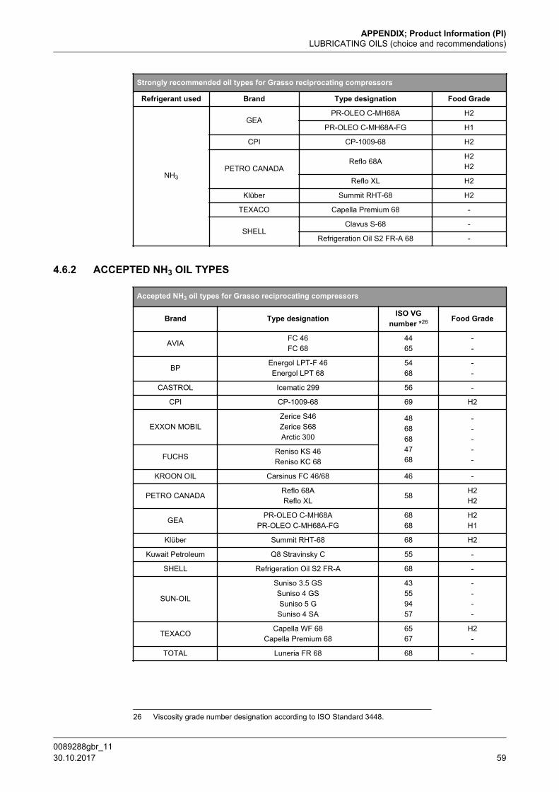
Strongly recommended oil types for Grasso reciprocating compressors
Refrigerant used Brand Type designation Food Grade
NH3
GEAPR-OLEO C-MH68A H2
PR-OLEO C-MH68A-FG H1
CPI CP-1009-68 H2
PETRO CANADAReflo 68A
H2H2
Reflo XL H2
Klüber Summit RHT-68 H2
TEXACO Capella Premium 68 -
SHELLClavus S-68 -
Refrigeration Oil S2 FR-A 68 -
4.6.2 ACCEPTED NH3 OIL TYPES
Accepted NH3 oil types for Grasso reciprocating compressors
Brand Type designation ISO VGnumber *26 Food Grade
AVIAFC 46FC 68
4465
--
BPEnergol LPT-F 46Energol LPT 68
5468
--
CASTROL Icematic 299 56 -
CPI CP-1009-68 69 H2
EXXON MOBILZerice S46Zerice S68Arctic 300
4868684768
-----FUCHS
Reniso KS 46Reniso KC 68
KROON OIL Carsinus FC 46/68 46 -
PETRO CANADAReflo 68AReflo XL
58H2H2
GEAPR-OLEO C-MH68A
PR-OLEO C-MH68A-FG6868
H2H1
Klüber Summit RHT-68 68 H2
Kuwait Petroleum Q8 Stravinsky C 55 -
SHELL Refrigeration Oil S2 FR-A 68 -
SUN-OIL
Suniso 3.5 GSSuniso 4 GSSuniso 5 GSuniso 4 SA
43559457
----
TEXACOCapella WF 68
Capella Premium 686567
H2-
TOTAL Luneria FR 68 68 -
26 Viscosity grade number designation according to ISO Standard 3448.
APPENDIX; Product Information (PI)LUBRICATING OILS (choice and recommendations)
0089288gbr_11 30.10.2017 59
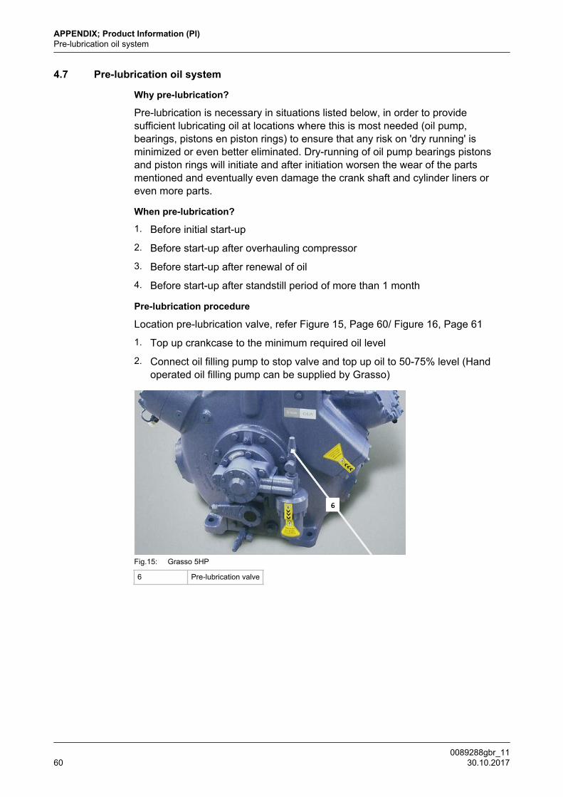
4.7 Pre-lubrication oil system
Why pre-lubrication?
Pre-lubrication is necessary in situations listed below, in order to providesufficient lubricating oil at locations where this is most needed (oil pump,bearings, pistons en piston rings) to ensure that any risk on 'dry running' isminimized or even better eliminated. Dry-running of oil pump bearings pistonsand piston rings will initiate and after initiation worsen the wear of the partsmentioned and eventually even damage the crank shaft and cylinder liners oreven more parts.
When pre-lubrication?
1. Before initial start-up
2. Before start-up after overhauling compressor
3. Before start-up after renewal of oil
4. Before start-up after standstill period of more than 1 month
Pre-lubrication procedure
Location pre-lubrication valve, refer Figure 15, Page 60/ Figure 16, Page 61
1. Top up crankcase to the minimum required oil level
2. Connect oil filling pump to stop valve and top up oil to 50-75% level (Handoperated oil filling pump can be supplied by Grasso)
Fig.15: Grasso 5HP
6 Pre-lubrication valve
APPENDIX; Product Information (PI)Pre-lubrication oil system
0089288gbr_1160 30.10.2017
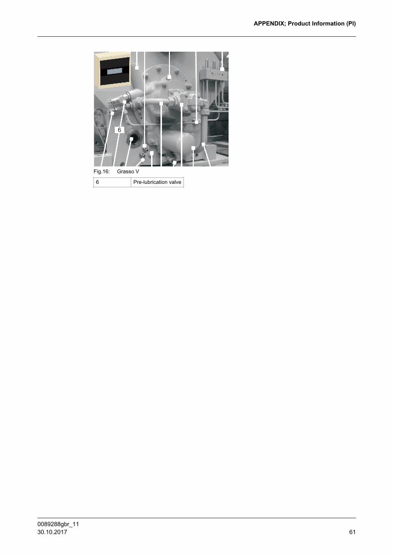
Fig.16: Grasso V
6 Pre-lubrication valve
APPENDIX; Product Information (PI)
0089288gbr_11 30.10.2017 61

GEA Group is a global engineering company with multi-billion euro sales and operations in more than 50 countries. Founded in 1881, the company is one of the largest providers of innovative equipment and process technology. GEA Group is listed in the STOXX® Europe 600 Index.
We live our values.Excellence • Passion • Integrity • Responsibility • GEA-versity
GEA RefrigerationGEA Refrigeration Netherlands N.V.Parallelweg 255223 AL ‘s-Hertogenbosch,Netherlands
Phone +31 (0)73 6203 911
[email protected] gea.com